EP4186429B1 - System und verfahren zur gewinnung genauer messungen und quantifizierung von röntgenbildern aus der schätzung von anatomischen schlüsselstellen - Google Patents
System und verfahren zur gewinnung genauer messungen und quantifizierung von röntgenbildern aus der schätzung von anatomischen schlüsselstellen Download PDFInfo
- Publication number
- EP4186429B1 EP4186429B1 EP22207479.1A EP22207479A EP4186429B1 EP 4186429 B1 EP4186429 B1 EP 4186429B1 EP 22207479 A EP22207479 A EP 22207479A EP 4186429 B1 EP4186429 B1 EP 4186429B1
- Authority
- EP
- European Patent Office
- Prior art keywords
- ray
- overlay
- key features
- anatomy
- ray image
- Prior art date
- Legal status (The legal status is an assumption and is not a legal conclusion. Google has not performed a legal analysis and makes no representation as to the accuracy of the status listed.)
- Active
Links
Images



Classifications
-
- G—PHYSICS
- G06—COMPUTING OR CALCULATING; COUNTING
- G06T—IMAGE DATA PROCESSING OR GENERATION, IN GENERAL
- G06T7/00—Image analysis
- G06T7/70—Determining position or orientation of objects or cameras
- G06T7/73—Determining position or orientation of objects or cameras using feature-based methods
- G06T7/74—Determining position or orientation of objects or cameras using feature-based methods involving reference images or patches
-
- A—HUMAN NECESSITIES
- A61—MEDICAL OR VETERINARY SCIENCE; HYGIENE
- A61B—DIAGNOSIS; SURGERY; IDENTIFICATION
- A61B6/00—Apparatus or devices for radiation diagnosis; Apparatus or devices for radiation diagnosis combined with radiation therapy equipment
-
- A—HUMAN NECESSITIES
- A61—MEDICAL OR VETERINARY SCIENCE; HYGIENE
- A61B—DIAGNOSIS; SURGERY; IDENTIFICATION
- A61B6/00—Apparatus or devices for radiation diagnosis; Apparatus or devices for radiation diagnosis combined with radiation therapy equipment
- A61B6/40—Arrangements for generating radiation specially adapted for radiation diagnosis
-
- A—HUMAN NECESSITIES
- A61—MEDICAL OR VETERINARY SCIENCE; HYGIENE
- A61B—DIAGNOSIS; SURGERY; IDENTIFICATION
- A61B6/00—Apparatus or devices for radiation diagnosis; Apparatus or devices for radiation diagnosis combined with radiation therapy equipment
- A61B6/40—Arrangements for generating radiation specially adapted for radiation diagnosis
- A61B6/4021—Arrangements for generating radiation specially adapted for radiation diagnosis involving movement of the focal spot
-
- A—HUMAN NECESSITIES
- A61—MEDICAL OR VETERINARY SCIENCE; HYGIENE
- A61B—DIAGNOSIS; SURGERY; IDENTIFICATION
- A61B6/00—Apparatus or devices for radiation diagnosis; Apparatus or devices for radiation diagnosis combined with radiation therapy equipment
- A61B6/44—Constructional features of apparatus for radiation diagnosis
- A61B6/4429—Constructional features of apparatus for radiation diagnosis related to the mounting of source units and detector units
-
- A—HUMAN NECESSITIES
- A61—MEDICAL OR VETERINARY SCIENCE; HYGIENE
- A61B—DIAGNOSIS; SURGERY; IDENTIFICATION
- A61B6/00—Apparatus or devices for radiation diagnosis; Apparatus or devices for radiation diagnosis combined with radiation therapy equipment
- A61B6/46—Arrangements for interfacing with the operator or the patient
- A61B6/461—Displaying means of special interest
-
- A—HUMAN NECESSITIES
- A61—MEDICAL OR VETERINARY SCIENCE; HYGIENE
- A61B—DIAGNOSIS; SURGERY; IDENTIFICATION
- A61B6/00—Apparatus or devices for radiation diagnosis; Apparatus or devices for radiation diagnosis combined with radiation therapy equipment
- A61B6/46—Arrangements for interfacing with the operator or the patient
- A61B6/461—Displaying means of special interest
- A61B6/466—Displaying means of special interest adapted to display 3D data
-
- A—HUMAN NECESSITIES
- A61—MEDICAL OR VETERINARY SCIENCE; HYGIENE
- A61B—DIAGNOSIS; SURGERY; IDENTIFICATION
- A61B6/00—Apparatus or devices for radiation diagnosis; Apparatus or devices for radiation diagnosis combined with radiation therapy equipment
- A61B6/50—Apparatus or devices for radiation diagnosis; Apparatus or devices for radiation diagnosis combined with radiation therapy equipment specially adapted for specific body parts; specially adapted for specific clinical applications
- A61B6/505—Apparatus or devices for radiation diagnosis; Apparatus or devices for radiation diagnosis combined with radiation therapy equipment specially adapted for specific body parts; specially adapted for specific clinical applications for diagnosis of bone
-
- A—HUMAN NECESSITIES
- A61—MEDICAL OR VETERINARY SCIENCE; HYGIENE
- A61B—DIAGNOSIS; SURGERY; IDENTIFICATION
- A61B6/00—Apparatus or devices for radiation diagnosis; Apparatus or devices for radiation diagnosis combined with radiation therapy equipment
- A61B6/52—Devices using data or image processing specially adapted for radiation diagnosis
-
- A—HUMAN NECESSITIES
- A61—MEDICAL OR VETERINARY SCIENCE; HYGIENE
- A61B—DIAGNOSIS; SURGERY; IDENTIFICATION
- A61B6/00—Apparatus or devices for radiation diagnosis; Apparatus or devices for radiation diagnosis combined with radiation therapy equipment
- A61B6/52—Devices using data or image processing specially adapted for radiation diagnosis
- A61B6/5205—Devices using data or image processing specially adapted for radiation diagnosis involving processing of raw data to produce diagnostic data
-
- A—HUMAN NECESSITIES
- A61—MEDICAL OR VETERINARY SCIENCE; HYGIENE
- A61B—DIAGNOSIS; SURGERY; IDENTIFICATION
- A61B6/00—Apparatus or devices for radiation diagnosis; Apparatus or devices for radiation diagnosis combined with radiation therapy equipment
- A61B6/52—Devices using data or image processing specially adapted for radiation diagnosis
- A61B6/5211—Devices using data or image processing specially adapted for radiation diagnosis involving processing of medical diagnostic data
- A61B6/5217—Devices using data or image processing specially adapted for radiation diagnosis involving processing of medical diagnostic data extracting a diagnostic or physiological parameter from medical diagnostic data
-
- A—HUMAN NECESSITIES
- A61—MEDICAL OR VETERINARY SCIENCE; HYGIENE
- A61B—DIAGNOSIS; SURGERY; IDENTIFICATION
- A61B6/00—Apparatus or devices for radiation diagnosis; Apparatus or devices for radiation diagnosis combined with radiation therapy equipment
- A61B6/52—Devices using data or image processing specially adapted for radiation diagnosis
- A61B6/5211—Devices using data or image processing specially adapted for radiation diagnosis involving processing of medical diagnostic data
- A61B6/5223—Devices using data or image processing specially adapted for radiation diagnosis involving processing of medical diagnostic data generating planar views from image data, e.g. extracting a coronal view from a 3D image
-
- A—HUMAN NECESSITIES
- A61—MEDICAL OR VETERINARY SCIENCE; HYGIENE
- A61B—DIAGNOSIS; SURGERY; IDENTIFICATION
- A61B6/00—Apparatus or devices for radiation diagnosis; Apparatus or devices for radiation diagnosis combined with radiation therapy equipment
- A61B6/52—Devices using data or image processing specially adapted for radiation diagnosis
- A61B6/5211—Devices using data or image processing specially adapted for radiation diagnosis involving processing of medical diagnostic data
- A61B6/5229—Devices using data or image processing specially adapted for radiation diagnosis involving processing of medical diagnostic data combining image data of a patient, e.g. combining a functional image with an anatomical image
-
- G—PHYSICS
- G06—COMPUTING OR CALCULATING; COUNTING
- G06T—IMAGE DATA PROCESSING OR GENERATION, IN GENERAL
- G06T17/00—Three-dimensional [3D] modelling for computer graphics
- G06T17/20—Finite element generation, e.g. wire-frame surface description, tesselation
-
- G—PHYSICS
- G06—COMPUTING OR CALCULATING; COUNTING
- G06T—IMAGE DATA PROCESSING OR GENERATION, IN GENERAL
- G06T7/00—Image analysis
- G06T7/0002—Inspection of images, e.g. flaw detection
- G06T7/0012—Biomedical image inspection
-
- G—PHYSICS
- G06—COMPUTING OR CALCULATING; COUNTING
- G06T—IMAGE DATA PROCESSING OR GENERATION, IN GENERAL
- G06T7/00—Image analysis
- G06T7/10—Segmentation; Edge detection
- G06T7/11—Region-based segmentation
-
- G—PHYSICS
- G06—COMPUTING OR CALCULATING; COUNTING
- G06T—IMAGE DATA PROCESSING OR GENERATION, IN GENERAL
- G06T7/00—Image analysis
- G06T7/30—Determination of transform parameters for the alignment of images, i.e. image registration
- G06T7/33—Determination of transform parameters for the alignment of images, i.e. image registration using feature-based methods
- G06T7/337—Determination of transform parameters for the alignment of images, i.e. image registration using feature-based methods involving reference images or patches
-
- G—PHYSICS
- G06—COMPUTING OR CALCULATING; COUNTING
- G06T—IMAGE DATA PROCESSING OR GENERATION, IN GENERAL
- G06T7/00—Image analysis
- G06T7/60—Analysis of geometric attributes
-
- G—PHYSICS
- G16—INFORMATION AND COMMUNICATION TECHNOLOGY [ICT] SPECIALLY ADAPTED FOR SPECIFIC APPLICATION FIELDS
- G16H—HEALTHCARE INFORMATICS, i.e. INFORMATION AND COMMUNICATION TECHNOLOGY [ICT] SPECIALLY ADAPTED FOR THE HANDLING OR PROCESSING OF MEDICAL OR HEALTHCARE DATA
- G16H30/00—ICT specially adapted for the handling or processing of medical images
- G16H30/40—ICT specially adapted for the handling or processing of medical images for processing medical images, e.g. editing
-
- G—PHYSICS
- G06—COMPUTING OR CALCULATING; COUNTING
- G06T—IMAGE DATA PROCESSING OR GENERATION, IN GENERAL
- G06T2207/00—Indexing scheme for image analysis or image enhancement
- G06T2207/10—Image acquisition modality
- G06T2207/10072—Tomographic images
- G06T2207/10081—Computed x-ray tomography [CT]
-
- G—PHYSICS
- G06—COMPUTING OR CALCULATING; COUNTING
- G06T—IMAGE DATA PROCESSING OR GENERATION, IN GENERAL
- G06T2207/00—Indexing scheme for image analysis or image enhancement
- G06T2207/10—Image acquisition modality
- G06T2207/10116—X-ray image
-
- G—PHYSICS
- G06—COMPUTING OR CALCULATING; COUNTING
- G06T—IMAGE DATA PROCESSING OR GENERATION, IN GENERAL
- G06T2207/00—Indexing scheme for image analysis or image enhancement
- G06T2207/20—Special algorithmic details
- G06T2207/20021—Dividing image into blocks, subimages or windows
-
- G—PHYSICS
- G06—COMPUTING OR CALCULATING; COUNTING
- G06T—IMAGE DATA PROCESSING OR GENERATION, IN GENERAL
- G06T2207/00—Indexing scheme for image analysis or image enhancement
- G06T2207/20—Special algorithmic details
- G06T2207/20081—Training; Learning
-
- G—PHYSICS
- G06—COMPUTING OR CALCULATING; COUNTING
- G06T—IMAGE DATA PROCESSING OR GENERATION, IN GENERAL
- G06T2207/00—Indexing scheme for image analysis or image enhancement
- G06T2207/20—Special algorithmic details
- G06T2207/20084—Artificial neural networks [ANN]
-
- G—PHYSICS
- G06—COMPUTING OR CALCULATING; COUNTING
- G06T—IMAGE DATA PROCESSING OR GENERATION, IN GENERAL
- G06T2207/00—Indexing scheme for image analysis or image enhancement
- G06T2207/30—Subject of image; Context of image processing
- G06T2207/30004—Biomedical image processing
- G06T2207/30008—Bone
-
- G—PHYSICS
- G06—COMPUTING OR CALCULATING; COUNTING
- G06T—IMAGE DATA PROCESSING OR GENERATION, IN GENERAL
- G06T2207/00—Indexing scheme for image analysis or image enhancement
- G06T2207/30—Subject of image; Context of image processing
- G06T2207/30168—Image quality inspection
Definitions
- the present disclosure relates to X-ray imaging systems, and more particularly to X-ray imaging systems including ancillary image processing systems to improve workflow and the quality of images produced by the X-ray systems.
- a number of X-ray imaging systems of various designs are known and are presently in use. Such systems are generally based upon generation of X-rays that are directed from an X-ray source toward a subject of interest. The X-rays traverse the subject and impinge on a detector, for example, a film, an imaging plate, or a portable cassette. The detector detects the X-rays, which are attenuated, scattered or absorbed by the intervening structures of the subject.
- such systems may be used to visualize the internal structures, tissues and organs of a subject for the purpose screening or diagnosing ailments.
- the radiologist or other medical practitioner it is desirable for a radiologist or other medical practitioner to obtain various angular and length measurements of the anatomical components illustrated in the X-ray image for diagnosis and other purposes.
- the radiologist it is necessary for the radiologist to be able to calculate the distances between different points and/or areas of the anatomy presented in the X-ray image. This process is normally accomplished utilizing a measurement algorithm formed as a part of or separate from the X-ray system that can provide these measurements.
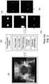
- a prior art AI model/algorithm 100 reviews the anatomy present within the X-ray image 102 input to the model 100 and performs an anatomy landmark segmentation on the anatomy.
- the anatomy landmark segmentation 105 identifies a number of particular and important areas, points or structures 104 of the anatomy in the X-ray image 102 that function as specified landmarks known by the measurement algorithm.
- the areas 104 are run through a complex geometric/trigonometry post-processing algorithm/computation 106 that provides the desired measurements 112 between the areas 104 shown in the X-ray image 102.
- prior art methods and systems for providing measurements of this type from X-ray images 102 include systems 108 incorporating a single AI model 100 ( FIG. 1 ) that performs a multiple landmark segmentations on the X-image 102, and alternative systems 110 that incorporate multiple AI models 100 ( FIG. 2 ), each AI model 100 configured to provide an anatomy segmentation 105 of a single area 104 of the anatomy illustrated in the X-ray image 102 that are subsequently stitched together prior to the post-processing/measurement calculation.
- the AI model(s) 200 analyzes the image 202 to locate various landmarks/structures known to be present in an image of a pelvis, such as the femur heads, the femur shafts, the pelvic teardrops, the acetabular sourcils and the acetabular lateral edges, among others.
- the AI model 200 proceeds to identify and locate the landmarks within the image 202, and segments the image 202 into various representations 204 of the important and/or desired structures of the pelvis. As shown in FIG.
- This measurement process results in highly accurate measurements for the anatomy represented in the X-ray image 202.
- the complexity of the computations for the image segmentation and for the post-processing requires a significant amount of memory and processing capability for the system performing the segmentation and post-processing, in addition to requiring a significant amount of time to complete.
- US20150272695A1 describes a computer implemented system for adjusting the placement of an implant in a patient through the use of a dimensioned grid template placed relative to patient anatomy on a fluoroscopic machine and a method to digitally quantify alignment parameters. This system can be used for determining leg length, offset, and cup position during arthroplasty replacement surgery.
- US20140323845A1 describes systems, methods, computer programs, and circuits that can perform automated spinal assessments using a 3-D model and a 3-D patient image data set of the spine which do not rely on vertebral symmetry.
- an artificial intelligence (AI) measurement system for an X-ray image is employed either as a component of the X-ray imaging system or separately from the X-ray imaging system to automatically scan post-exposure X-ray images to detect and locate various landmarks of the anatomy presented within the X-ray image.
- a set of key image features approximating the locations of the landmarks having known distance relationships to one another is overlaid onto the X-ray image.
- the positions of the key image features are then adjusted to correspond to the landmarks within the X-ray image.
- the AI measurement system can utilize key points, key lines or key areas alone or in combination with one another as the key features to calculate various angular and length measurements for an anatomy illustrated in an X-ray image.
- an X-ray system includes an X-ray source, an X-ray detector positionable in alignment with the X-ray ray source, and a processing unit operably connected to the X-ray source and the X-ray detector to produce X-ray images from data transmitted from the X-ray detector, wherein the processing unit includes an X-ray measurement system configured to provide an overlay of one or more key features corresponding to one or more landmarks of an anatomy within the X-ray images, and to calculate a measurement of the anatomy based on the positions of the key features within the overlay.
- a method of determining measurements between landmarks of an anatomy within an X-ray image includes the steps of providing an X-ray system having an X-ray source, an X-ray detector positionable in alignment with the X-ray ray source, and a processing unit operably connected to the X-ray source and the X-ray detector to produce X-ray images from data transmitted from the X-ray detector, wherein the processing unit includes an X-ray measurement system configured to provide an overlay of one or more key features corresponding to one or more landmarks of an anatomy within the X-ray images, and to calculate measurements of the anatomy based on the positions of the one or more key features in the overlay, applying the overlay to the X-ray image and calculating a measurement of the anatomy in the X-ray image based on the position of the one or more key features in the overlay applied X-ray image.
- the articles “a,” “an,” “the,” and “said” are intended to mean that there are one or more of the elements.
- the terms “comprising,” “including,” and “having” are intended to be inclusive and mean that there may be additional elements other than the listed elements.
- any numerical examples in the following discussion are intended to be non-limiting, and thus additional numerical values, ranges, and percentages are within the scope of the disclosed embodiments.
- the terms “substantially,” “generally,” and “about” indicate conditions within reasonably achievable manufacturing and assembly tolerances, relative to ideal desired conditions suitable for achieving the functional purpose of a component or assembly.
- connection may include a direct conductive connection, i.e., without an intervening capacitive, inductive or active element, an inductive connection, a capacitive connection, and/or any other suitable electrical connection. Intervening components may be present.
- real-time means a level of processing responsiveness that a user senses as sufficiently immediate or that enables the processor to keep up with an external process.
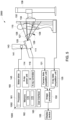
- the x-ray imaging system 2000 includes an x-ray source 111 which radiates x-rays, a stand 132 upon which the subject 105 stands during an examination, and an x-ray detector 134 for detecting x-rays radiated by the x-ray source 111 and attenuated by the subject 115.
- the x-ray detector 134 may comprise, as non-limiting examples, a scintillator, one or more ion chamber(s), a light detector array, an x-ray exposure monitor, an electric substrate, and so on.
- the x-ray detector 134 is mounted on a stand 138 and is configured so as to be vertically moveable according to an imaged region of the subject.
- the operation console 160 comprises a processor 161, a memory 162, a user interface 163, a motor drive 145 for controlling one or more motors 143, an x-ray power unit 114, an x-ray controller 116, a camera data acquisition unit 121, an x-ray data acquisition unit 135, and an image processor 150.
- X-ray image data transmitted from the x-ray detector 134 is received by the x-ray data acquisition unit 135.
- the collected x-ray image data are image-processed by the image processor 150.
- a display device 155 communicatively coupled to the operating console 160 displays an image-processed x-ray image thereon.
- the x-ray source 111 is supported by a support post 141 which may be mounted to a ceiling (e.g., as depicted) or mounted on a moveable stand for positioning within an imaging room.
- the x-ray source 111 is vertically moveable relative to the subject or patient 105.
- one of the one or more motors 143 may be integrated into the support post 141 and may be configured to adjust a vertical position of the x-ray source 111 by increasing or decreasing the distance of the x-ray source 111 from the ceiling or floor, for example.
- the motor drive 145 of the operation console 160 may be communicatively coupled to the one or more motors 143 and configured to control the one or more motors 143.
- the one or more motors 143 may further be configured to adjust an angular position of the x-ray source 111 to change a field-of-view of the x-ray source 111, as described further herein.
- the x-ray power unit 114 and the x-ray controller 116 supply power of a suitable voltage current to the x-ray source 111.
- a collimator (not shown) may be fixed to the x-ray source 111 for designating an irradiated field-of-view of an x-ray beam.
- the x-ray beam radiated from the x-ray source 111 is applied onto the subject via the collimator.
- the x-ray source 111 and the camera 120 may pivot or rotate relative to the support post 141 in an angular direction 129 to image different portions of the subject 105.
- Memory 162 is a suitable electronic storage medium and/or computer-readable medium that stores x-ray images 170 and executable instructions 172 that when executed cause one or more of the processor 161 and the image processor 150 to perform one or more actions.
- Example methods that may be stored as the executable instructions 172 are described further herein with regard to the X-ray measurement system 1000 and AI application 1002 of FIG. 5 .
- the processor 161 additionally includes an automatic X-ray measurement system 1000, optionally stored in memory 162 as a part of the executable instructions 172 employed by the processor 161 to perform the functions of the measurement system 1000. While the measurement system 1000 is illustrated and described as being employed in conjunction with an X-ray system 2000, the measurement system 1000 is also contemplated as being used with other types of imaging systems, including, but not limited to, computed tomography (CT) systems, magnetic resonance (MRI) imaging systems, and ultrasound (US) systems, among other compatible imaging systems.
- CT computed tomography
- MRI magnetic resonance
- US ultrasound
- the X-ray measurement system 1000 is formed by an artificial intelligence (AI) application 1002 that can scan and detect various types of information associated with a post-exposure X-ray image 1004 ( FIGS. 6-9 ).
- AI artificial intelligence
- the AI application 1002 which can be a deep learning neural network, for example, is an image-based object detection application that is configured for the detection various attributes of the post-exposure X-ray image 1004, such as information regarding various landmarks located in the anatomy presented within the X-ray image 1004.
- the AI application 1002 creates an overlay 300 ( FIGS. 7A , 8A ) of a number of key features 302 that correspond to an estimated or approximated location of each of a corresponding number of landmarks 304 found within a selected anatomy 306 that is presented in the X-ray image 1004.
- the estimation of the locations of the key features 302 can be done in any suitable manner, such as a through the use of a training set of X-ray images to enable the system 1000/AI application 1002 to determine the locations of each landmark 304 in the training images and determine an average position of the landmarks 304 in the set of training images to be used for the location of the key feature(s) 302 in the overlay 300 for the anatomy 306 or for one or more different anatomies 306 present within the X-ray image 1004.
- the distances, angles and other measurements between each of the key features 302 is known, such that any desired measurement can be readily and directly determined from the known relationships of the positions of the key features 302 relative to one another.
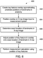
- an X-ray image 1004 is supplied or input to the system 1000 and the system 1000 positions the overlay 300 onto the anatomy 306 within the X-ray image 1004, such as on the display 46, to provide a visual indication of the overlay 300 with respect to the X-ray image 1004.
- the system 1000 analyzes the X-ray image 1004 utilizing any suitable image review process or method employed by the AI application 1002 in order to determine the exact locations of the landmarks 304 associated with each of the key features 302 forming the overlay 300.
- the AI application 1002 After determining the exact location of each landmark 304 within the X-ray image 1004, in block 408 the AI application 1002 proceeds to adjust or edit the position of each associated key feature 302 for the landmarks 304, if necessary, such that position of the key feature 302 in the overlay 300 corresponds exactly to the location of the associated landmark 304 in the X-ray image 1004.
- the adjustment of the key features 302 can alternatively or in association with the AI application 1002, be conducted by the user, such as by moving the position of one or more of the key features 302 in the overly 300 on the X-ray image 1004 via the user interface 44.
- the steps in block 404-408 can be reversed or altered in order, such that, for example, the AI application 1002 can determine the exact position of the landmarks 304 prior to without positioning the overlay 300 on the anatomy 306 in the X-ray image 1004, and/or the adjustment of the positions of the key features 302 in the overlay 300 can be performed prior to or without positioning the overlay 300 on the X-ray image 1004.
- the step in block 204 of positioning the overlay 300 on the X-ray image 1004 can be moved to after the adjustment of the positions of the key features 302, in order to provide a visual representation of the overlay 300 on the anatomy 306 of the X-ray image only after all adjustments have been performed.
- the entire process of the method 400 can be maintained as an internal process within the system 1000, with no visual representation of the overlay 300 being presented, e.g., on the display 46.
- the form of the features 302 can be selected by the user and/or by the AI application 102 as desired, such as depending upon the anatomy 306 to be presented within the X-ray image 1004, with different anatomies 306 having different key feature(s) 302.
- the one or more key feature(s) 302 can take the form of one or more key points 312, one or more key lines 314 and/or one or more key areas 316, and combinations thereof.
- the various types of key features 302 can be illustrated on the display 46 in various manners, such as by changing types (e.g., points, crosses, etc.), color, size, flashing or other attributes of a key feature(s) 302 currently being analyzed and/or reviewed by the AI application 102.
- FIG. 7A an anatomy 306 of an X-ray image 1004 including anatomical landmarks 304 is shown positioned next to an overlay 300 containing a number of key features 302 in the form of key points 312.
- the overlay 300 is also shown disposed over the anatomy 306 in the X-ray image 1004, with the positions of the key points 312 adjusted from the positions in the stand-alone overlay 300 to be disposed directly over the landmarks 304 detected in the X-ray image 1004 associated with each of the key points 312.
- This X-ray image 1004 is juxtaposed in FIG.
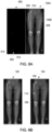
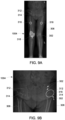
- FIGS. 8A-8B A second example of the process of the method 400 is illustrated in FIGS. 8A-8B where the overlay 300 in FIG. 8A includes a smaller number key features 302 in the form of key points 312 within the overlay 300, which are positioned over the landmarks 304 in the X-ray image 1004.
- the overlay 300 on the image 1004 is again compared with FIG. 8B showing the segmented structure 206 produced in the prior art method.
- FIGS. 8A and 8B each illustrate an exemplary measurement line, with the line being a distance measurement line 212 ( FIG. 8B ) taken between two (2) landmarks 204 on the segmented structure 206 via the prior art method, in contrast to the distance measurement line 1006 ( FIG. 8A ) obtained by the system 1000 in the current method 400 corresponding to the known distance between two (2) key points 312 associated with landmarks 304 on the anatomy 306 in the X-ray image 1004.
- FIGS. 9A-9B illustrate an alternative embodiment of the X-ray image 1004 output by the system 1000/AI application 1002 where the overlay 300 provided on the image 1004 includes key features 302 in the form of key points 312, key lines 314 and key areas 316 corresponding to the various landmarks 304 in the X-ray image 1004.
- the representations of the key points 312, key lines 314 and key areas 316 corresponding to the various landmarks 304 in the X-ray image 1004 have determined in a suitable training for the system 1000/AI application 1002 where the average locations of the key points 312, key lines 314 and key areas 316 corresponding to the various landmarks 304 in a particular anatomy 306 are determined from a dataset including a number of X-ray images 1004 of the anatomy 306 supplied to the system 1000/AI application 1002.
- the various key points 312, key lines 314 and key areas 316 in the anatomy 306 are subsequently adjusted automatically by the system 1000/AI application 1002 and/or manually by the user, to position the key points 312, key lines 314 and key areas 316 directly over the corresponding landmarks in the anatomy 306 to form the overlay 300.
- the system 1000/AI application 1002 can readily calculate the required measurements within the anatomy 306 presented in the X-ray image 1004 based on the prior know relationships between the various key points 312, key lines 314 and key areas 316 and the adjustments made to these relationships in the formation of the overlay 300. Further, the system 1000/AI application 1002 can be trained to
- the system 1000AI application 1002 may include the necessary computer, electronics, software, memory, storage, databases, firmware, logic/state machines, microprocessors, communication links, displays or other visual or audio user interfaces, printing devices, and any other input/output interfaces to perform the functions described herein and/or to achieve the results described herein.
- the system may include at least one processor/processing unit/computer and system memory/data storage structures, which may include random access memory (RAM) and read-only memory (ROM).
- the at least one processor of the system may include one or more conventional microprocessors and one or more supplementary co-processors such as math co-processors or the like.
- the data storage structures discussed herein may include an appropriate combination of magnetic, optical and/or semiconductor memory, and may include, for example, RAM, ROM, flash drive, an optical disc such as a compact disc and/or a hard disk or drive.
- a software application(s)/algorithm(s) that adapts the computer/controller to perform the methods disclosed herein may be read into a main memory of the at least one processor from a computer-readable medium.
- computer-readable medium refers to any medium that provides or participates in providing instructions to the at least one processor of the system 10,1000 (or any other processor of a device described herein) for execution. Such a medium may take many forms, including but not limited to, non-volatile media and volatile media.
- Non-volatile media include, for example, optical, magnetic, or opto-magnetic disks, such as memory.
- Volatile media include dynamic random access memory (DRAM), which typically constitutes the main memory.
- Computer-readable media include, for example, a floppy disk, a flexible disk, hard disk, magnetic tape, any other magnetic medium, a CD-ROM, DVD, any other optical medium, a RAM, a PROM, an EPROM or EEPROM (electronically erasable programmable read-only memory), a FLASH-EEPROM, any other memory chip or cartridge, or any other medium from which a computer can read.
- compositions, apparatuses and methods of this disclosure are not limited to the particular embodiments and methodology, as these may vary. It is also understood that the terminology used herein is for the purpose of describing particular exemplary embodiments only, and is not intended to limit the scope of the present disclosure which will be limited only by the appended claims.
Landscapes
- Engineering & Computer Science (AREA)
- Health & Medical Sciences (AREA)
- Life Sciences & Earth Sciences (AREA)
- Medical Informatics (AREA)
- Physics & Mathematics (AREA)
- Radiology & Medical Imaging (AREA)
- General Health & Medical Sciences (AREA)
- Nuclear Medicine, Radiotherapy & Molecular Imaging (AREA)
- Public Health (AREA)
- Animal Behavior & Ethology (AREA)
- High Energy & Nuclear Physics (AREA)
- Optics & Photonics (AREA)
- Biomedical Technology (AREA)
- Heart & Thoracic Surgery (AREA)
- Molecular Biology (AREA)
- Surgery (AREA)
- Pathology (AREA)
- Biophysics (AREA)
- Veterinary Medicine (AREA)
- Computer Vision & Pattern Recognition (AREA)
- General Physics & Mathematics (AREA)
- Theoretical Computer Science (AREA)
- Physiology (AREA)
- Human Computer Interaction (AREA)
- Geometry (AREA)
- Primary Health Care (AREA)
- Epidemiology (AREA)
- Computer Graphics (AREA)
- Software Systems (AREA)
- Quality & Reliability (AREA)
- Orthopedic Medicine & Surgery (AREA)
- Dentistry (AREA)
- Oral & Maxillofacial Surgery (AREA)
- Apparatus For Radiation Diagnosis (AREA)
Claims (11)
- Verfahren zum Bestimmen von Messungen zwischen Landmarken (304) einer Anatomie (306) innerhalb eines Röntgenbildes (102, 202), umfassend die folgenden Schritte:- Bereitstellen eines Röntgensystems (10), das Folgendes umfasst:- eine Röntgenquelle (14);- einen Röntgendetektor (18), der in Ausrichtung mit der Röntgenquelle (14) positionierbar ist; und- eine Verarbeitungseinheit (40), die funktionell mit der Röntgenquelle (14) und dem Röntgendetektor (18) verbunden ist, um Röntgenbilder (102, 202) aus Daten zu erzeugen, die von dem Röntgendetektor (18) übertragen werden, wobei die Verarbeitungseinheit (40) ein Röntgenmesssystem (1000) beinhaltet, das dazu ausgelegt ist, eine Überlagerung (300) eines oder mehrerer Schlüsselmerkmale (302) bereitzustellen, die einer oder mehreren Landmarken (304) einer Anatomie (306) innerhalb der Röntgenbilder (102, 202) entsprechen, und Messungen (112) der Anatomie (306) basierend auf den Positionen des einen oder der mehreren Schlüsselmerkmale (302) in der Überlagerung (300) zu berechnen;- Anwenden der Überlagerung (300) auf das Röntgenbild (102, 202);- Anpassen der Position des einen oder der mehreren Schlüsselmerkmale (302) innerhalb der Überlagerung (300) in Ausrichtung mit der einen oder den mehreren assoziierten Landmarken (304) in dem Röntgenbild (102, 202); und- Berechnen einer Messung (112) der Anatomie (306) in dem Röntgenbild (102, 202) basierend auf der Position des einen oder der mehreren Schlüsselmerkmale (302) in der Überlagerung (300), die auf das Röntgenbild (102, 202) angewendet wird.
- Verfahren nach Anspruch 1, wobei das Röntgenmesssystem (1000) eine Anwendung (1002) künstlicher Intelligenz (KI) umfasst.
- Verfahren nach Anspruch 2, wobei die KI-Anwendung (1002) trainiert wird, um die Überlagerung (300) bereitzustellen, indem die Stellen jeder oder mehrerer Landmarken (304) in einem Trainingssatz von Röntgenbildern bestimmt werden und eine durchschnittliche Position der einen oder der mehreren Landmarken (304) in dem Satz von Trainingsbildern bestimmt wird, wobei die durchschnittlichen Positionen für die Stelle des einen oder der mehreren Schlüsselmerkmale (302) in der Überlagerung (300) für die Anatomie (306) oder für eine oder mehrere verschiedene Anatomien (306) verwendet werden, die innerhalb des Röntgenbildes vorhanden sind.
- Verfahren nach Anspruch 2, wobei das eine oder die mehreren Schlüsselmerkmale (302) die Form annehmen von:einem oder mehreren Schlüsselpunkten (312);einer oder mehreren Schlüssellinien (314);einem oder mehreren Schlüsselbereichen (316); odereiner Kombination davon.
- Verfahren nach Anspruch 1, wobei der Schritt des Anwendens der Überlagerung (300) auf das Röntgenbild (102, 202) Darstellen der Überlagerung (300) in Verbindung mit dem Röntgenbild (102, 202) auf einer Anzeige (46) umfasst.
- Verfahren nach Anspruch 1, wobei der Schritt des Anpassens der Position des einen oder der mehreren Schlüsselmerkmale (302) innerhalb der Überlagerung (300) in Ausrichtung mit der einen oder den mehreren assoziierten Landmarken (304) in dem Röntgenbild (102, 202) automatisch durch das Röntgenmesssystem (100) durchgeführt wird.
- Verfahren nach Anspruch 1, wobei der Schritt des Anpassens der Position des einen oder der mehreren Schlüsselmerkmale (302) innerhalb der Überlagerung (300) relativ zu der einen oder den mehreren Landmarken (304) in dem Röntgenbild (102, 202) Folgendes umfasst:- Bewegen des einen oder der mehreren Schlüsselmerkmale (302), um das eine oder die mehreren Schlüsselmerkmale (302) mit einer entsprechenden Landmarke (304) in der Anatomie (306) auszurichten; und- Bestimmen einer angepassten Position des einen oder der mehreren Schlüsselmerkmale (302) innerhalb der Überlagerung (300).
- Röntgensystem (10), umfassend:- eine Röntgenquelle (14);- einen Röntgendetektor (18), der in Ausrichtung mit der Röntgenquelle (14) positionierbar ist; und- eine Verarbeitungseinheit (40), die funktionell mit der Röntgenquelle (14) und dem Röntgendetektor (18) verbunden ist, um Röntgenbilder (102, 202) aus Daten zu erzeugen, die von dem Röntgendetektor (18) übertragen werden,wobei die Verarbeitungseinheit (40) ein Röntgenmesssystem (1000) beinhaltet, das eine Anwendung (1002) künstlicher Intelligenz (KI) umfasst, die zu Folgendem ausgelegt ist:Bereitstellen einer Überlagerung (300) eines oder mehrerer Schlüsselmerkmale (302), die einer oder mehreren Landmarken (304) einer Anatomie (306) innerhalb der Röntgenbilder (102, 202) entsprechen;Anpassen der Position des einen oder der mehreren Schlüsselmerkmale (302) innerhalb der Überlagerung (300) in Ausrichtung mit der einen oder den mehreren assoziierten Landmarken (304) in dem Röntgenbild (102, 202); undBerechnen einer Messung (112) der Anatomie (306) basierend auf den Positionen der Schlüsselmerkmale (302) innerhalb der Überlagerung (300).
- Röntgensystem nach Anspruch 8, wobei die KI-Anwendung (1002) trainiert wird, um die Überlagerung (300) bereitzustellen, indem die Stellen jeder oder mehrerer Landmarken (304) in einem Trainingssatz von Röntgenbildern bestimmt werden und eine durchschnittliche Position der einen oder der mehreren Landmarken (304) in dem Satz von Trainingsbildern bestimmt wird, wobei die durchschnittlichen Positionen für die Stelle des einen oder der mehreren Schlüsselmerkmale (302) in der Überlagerung (300) für die Anatomie (306) oder für eine oder mehrere verschiedene Anatomien (306) verwendet werden, die innerhalb des Röntgenbildes vorhanden sind.
- Röntgensystem nach Anspruch 8, wobei die KI-Anwendung (1002) dazu ausgelegt ist, die Messung (112) der Anatomie (306) basierend auf der Position des einen oder der mehreren Schlüsselmerkmale (302) in der Überlagerung (300) durch Bestimmen der Messung (112) eines Schlüsselmerkmals (302) relativ zu einem anderen Schlüsselmerkmal (302) zu berechnen.
- Computerlesbares Medium, umfassend Anweisungen, die bei Ausführung durch eine Verarbeitungseinheit (40) eines Röntgensystems (10) die Verarbeitungseinheit (40) zu Folgendem veranlassen:- Anwenden einer Überlagerung (300) eines oder mehrerer Schlüsselmerkmale (302), die einer oder mehreren Landmarken (304) einer Anatomie (306) entsprechen, auf ein Röntgenbild (102, 202), das durch das Röntgensystem (10) erzeugt wird;- Anpassen der Position des einen oder der mehreren Schlüsselmerkmale (302) innerhalb der Überlagerung (300) in Ausrichtung mit einer oder mehreren assoziierten Landmarken (304) in dem Röntgenbild (102, 202); und- Berechnen einer Messung (112) der Anatomie (306) in dem Röntgenbild (102, 202) basierend auf der Position des einen oder der mehreren Schlüsselmerkmale (302) in der Überlagerung (300), die auf das Röntgenbild (102, 202) angewendet wird.
Applications Claiming Priority (2)
| Application Number | Priority Date | Filing Date | Title |
|---|---|---|---|
| US202163283350P | 2021-11-26 | 2021-11-26 | |
| US17/975,889 US12567172B2 (en) | 2021-11-26 | 2022-10-28 | System and method for obtaining accurate measurements and quantification of x-ray image from estimation of key anatomical locations |
Publications (2)
| Publication Number | Publication Date |
|---|---|
| EP4186429A1 EP4186429A1 (de) | 2023-05-31 |
| EP4186429B1 true EP4186429B1 (de) | 2025-03-05 |
Family
ID=84358013
Family Applications (1)
| Application Number | Title | Priority Date | Filing Date |
|---|---|---|---|
| EP22207479.1A Active EP4186429B1 (de) | 2021-11-26 | 2022-11-15 | System und verfahren zur gewinnung genauer messungen und quantifizierung von röntgenbildern aus der schätzung von anatomischen schlüsselstellen |
Country Status (3)
| Country | Link |
|---|---|
| US (1) | US12567172B2 (de) |
| EP (1) | EP4186429B1 (de) |
| CN (1) | CN116172586A (de) |
Family Cites Families (9)
| Publication number | Priority date | Publication date | Assignee | Title |
|---|---|---|---|---|
| CN101325912B (zh) * | 2005-12-15 | 2011-01-12 | 皇家飞利浦电子股份有限公司 | 用于在电生理标测和治疗期间显现心脏形态的系统和方法 |
| US11020189B2 (en) * | 2012-10-02 | 2021-06-01 | Radlink, Inc. | System and method for component positioning by registering a 3D patient model to an intra-operative image |
| AU2014217929B2 (en) | 2013-02-18 | 2018-04-19 | Orthogrid Systems, Inc. | Alignment plate apparatus and system and method of use |
| US9561004B2 (en) | 2013-04-29 | 2017-02-07 | Sectra Ab | Automated 3-D orthopedic assessments |
| US20160331463A1 (en) * | 2014-01-10 | 2016-11-17 | Ao Technology Ag | Method for generating a 3d reference computer model of at least one anatomical structure |
| US10568602B2 (en) * | 2017-09-06 | 2020-02-25 | General Electric Company | Virtual positioning image for use in imaging |
| US10918346B2 (en) * | 2017-09-06 | 2021-02-16 | General Electric Company | Virtual positioning image for use in imaging |
| WO2019051464A1 (en) * | 2017-09-11 | 2019-03-14 | Lang Philipp K | INCREASED REALITY DISPLAY FOR VASCULAR AND OTHER INTERVENTIONS, COMPENSATION FOR CARDIAC AND RESPIRATORY MOVEMENT |
| US20210391058A1 (en) * | 2020-06-16 | 2021-12-16 | Globus Medical, Inc. | Machine learning system for navigated orthopedic surgeries |
-
2022
- 2022-10-28 US US17/975,889 patent/US12567172B2/en active Active
- 2022-11-15 EP EP22207479.1A patent/EP4186429B1/de active Active
- 2022-11-21 CN CN202211457824.2A patent/CN116172586A/zh active Pending
Also Published As
| Publication number | Publication date |
|---|---|
| EP4186429A1 (de) | 2023-05-31 |
| US20230169682A1 (en) | 2023-06-01 |
| US12567172B2 (en) | 2026-03-03 |
| CN116172586A (zh) | 2023-05-30 |
Similar Documents
| Publication | Publication Date | Title |
|---|---|---|
| EP3453330B1 (de) | Virtuelles positionierungsbild zur verwendung bei der bilderzeugung | |
| US11497459B2 (en) | Methods and system for optimizing an imaging scan based on a prior scan | |
| JP4532005B2 (ja) | X線ct装置及びその画像表示方法 | |
| US20050027193A1 (en) | Method for automatically merging a 2D fluoroscopic C-arm image with a preoperative 3D image with one-time use of navigation markers | |
| JP7513980B2 (ja) | 医用画像処理装置、治療システム、医用画像処理方法、およびプログラム | |
| US20240161274A1 (en) | System and Method for Exposure Control and Imaging Technique Optimization Employing a Preshot X-Ray Image | |
| EP4561448B1 (de) | Computertomograph und abtastverfahren zum durchführen einer gehirnabtastung | |
| US12462920B2 (en) | Planning of wide-coverage axial CT scans | |
| US7856080B2 (en) | Method for determining a defined position of a patient couch in a C-arm computed tomography system, and C-arm computed tomography system | |
| US12567172B2 (en) | System and method for obtaining accurate measurements and quantification of x-ray image from estimation of key anatomical locations | |
| JP5027909B2 (ja) | X線ct装置 | |
| US12318239B2 (en) | X-ray lead marker detection system for x-ray imaging system | |
| JP5073484B2 (ja) | 画像処理をするための方法、コンピュータプログラム、装置及びイメージングシステム | |
| JP7112343B2 (ja) | 医療用x線測定装置及びプログラム | |
| US12236593B2 (en) | System and method for automatic detection and correction of anatomy, view, orientation and laterality in X-ray image for X-ray imaging system | |
| US20250090125A1 (en) | Predicting the diagnostic certainty | |
| JP4644292B2 (ja) | X線ct装置とその画像表示方法 | |
| US20250359838A1 (en) | Predicting artifacts in 3d imaging | |
| EP4491125A1 (de) | Simulierte 4d-ct-überblicke mit 3d-überblick und rgb-d-kamera für verbesserte scan-planung | |
| EP3375372B1 (de) | System und verfahren zur übertragung eines oder mehrerer prädiktiver indikatoren eines bildsteuerungsparameters | |
| Cai et al. | Rotating projection based localizer radiograph: attenuation calculation optimization and patient automatic centering with parallel-beam projection scheme | |
| Rhode¹ et al. | David Hawkes¹'Division of Radiological Sciences and Medical Engineering, Guy's, King's and St. Thomas' Hospitals Medical School, Guy's Hospital, London, UK, SE1 9RT 2University Department of Surgery, Royal Free and University College Medical School | |
| Boehm et al. | Texture analysis of clinical radiographs using radon transform on a local scale for differentiation between post-menopausal women with and without hip fracture |
Legal Events
| Date | Code | Title | Description |
|---|---|---|---|
| PUAI | Public reference made under article 153(3) epc to a published international application that has entered the european phase |
Free format text: ORIGINAL CODE: 0009012 |
|
| STAA | Information on the status of an ep patent application or granted ep patent |
Free format text: STATUS: REQUEST FOR EXAMINATION WAS MADE |
|
| 17P | Request for examination filed |
Effective date: 20221115 |
|
| AK | Designated contracting states |
Kind code of ref document: A1 Designated state(s): AL AT BE BG CH CY CZ DE DK EE ES FI FR GB GR HR HU IE IS IT LI LT LU LV MC ME MK MT NL NO PL PT RO RS SE SI SK SM TR |
|
| REG | Reference to a national code |
Ref country code: DE Ref legal event code: R079 Free format text: PREVIOUS MAIN CLASS: A61B0006000000 Ipc: A61B0006460000 Ref document number: 602022011379 Country of ref document: DE |
|
| GRAP | Despatch of communication of intention to grant a patent |
Free format text: ORIGINAL CODE: EPIDOSNIGR1 |
|
| STAA | Information on the status of an ep patent application or granted ep patent |
Free format text: STATUS: GRANT OF PATENT IS INTENDED |
|
| RIC1 | Information provided on ipc code assigned before grant |
Ipc: A61B 6/00 20060101ALI20240430BHEP Ipc: G06T 7/60 20170101ALI20240430BHEP Ipc: A61B 6/46 20240101AFI20240430BHEP |
|
| INTG | Intention to grant announced |
Effective date: 20240515 |
|
| GRAJ | Information related to disapproval of communication of intention to grant by the applicant or resumption of examination proceedings by the epo deleted |
Free format text: ORIGINAL CODE: EPIDOSDIGR1 |
|
| STAA | Information on the status of an ep patent application or granted ep patent |
Free format text: STATUS: REQUEST FOR EXAMINATION WAS MADE |
|
| GRAP | Despatch of communication of intention to grant a patent |
Free format text: ORIGINAL CODE: EPIDOSNIGR1 |
|
| STAA | Information on the status of an ep patent application or granted ep patent |
Free format text: STATUS: GRANT OF PATENT IS INTENDED |
|
| INTC | Intention to grant announced (deleted) | ||
| INTG | Intention to grant announced |
Effective date: 20240926 |
|
| GRAS | Grant fee paid |
Free format text: ORIGINAL CODE: EPIDOSNIGR3 |
|
| GRAA | (expected) grant |
Free format text: ORIGINAL CODE: 0009210 |
|
| STAA | Information on the status of an ep patent application or granted ep patent |
Free format text: STATUS: THE PATENT HAS BEEN GRANTED |
|
| AK | Designated contracting states |
Kind code of ref document: B1 Designated state(s): AL AT BE BG CH CY CZ DE DK EE ES FI FR GB GR HR HU IE IS IT LI LT LU LV MC ME MK MT NL NO PL PT RO RS SE SI SK SM TR |
|
| REG | Reference to a national code |
Ref country code: GB Ref legal event code: FG4D |
|
| REG | Reference to a national code |
Ref country code: CH Ref legal event code: EP |
|
| P01 | Opt-out of the competence of the unified patent court (upc) registered |
Free format text: CASE NUMBER: APP_8132/2025 Effective date: 20250218 |
|
| REG | Reference to a national code |
Ref country code: IE Ref legal event code: FG4D |
|
| REG | Reference to a national code |
Ref country code: DE Ref legal event code: R096 Ref document number: 602022011379 Country of ref document: DE |
|
| PG25 | Lapsed in a contracting state [announced via postgrant information from national office to epo] |
Ref country code: RS Free format text: LAPSE BECAUSE OF FAILURE TO SUBMIT A TRANSLATION OF THE DESCRIPTION OR TO PAY THE FEE WITHIN THE PRESCRIBED TIME-LIMIT Effective date: 20250605 |
|
| PG25 | Lapsed in a contracting state [announced via postgrant information from national office to epo] |
Ref country code: FI Free format text: LAPSE BECAUSE OF FAILURE TO SUBMIT A TRANSLATION OF THE DESCRIPTION OR TO PAY THE FEE WITHIN THE PRESCRIBED TIME-LIMIT Effective date: 20250305 |
|
| REG | Reference to a national code |
Ref country code: NL Ref legal event code: MP Effective date: 20250305 |
|
| PG25 | Lapsed in a contracting state [announced via postgrant information from national office to epo] |
Ref country code: ES Free format text: LAPSE BECAUSE OF FAILURE TO SUBMIT A TRANSLATION OF THE DESCRIPTION OR TO PAY THE FEE WITHIN THE PRESCRIBED TIME-LIMIT Effective date: 20250305 |
|
| REG | Reference to a national code |
Ref country code: LT Ref legal event code: MG9D |
|
| PG25 | Lapsed in a contracting state [announced via postgrant information from national office to epo] |
Ref country code: NO Free format text: LAPSE BECAUSE OF FAILURE TO SUBMIT A TRANSLATION OF THE DESCRIPTION OR TO PAY THE FEE WITHIN THE PRESCRIBED TIME-LIMIT Effective date: 20250605 |
|
| PG25 | Lapsed in a contracting state [announced via postgrant information from national office to epo] |
Ref country code: HR Free format text: LAPSE BECAUSE OF FAILURE TO SUBMIT A TRANSLATION OF THE DESCRIPTION OR TO PAY THE FEE WITHIN THE PRESCRIBED TIME-LIMIT Effective date: 20250305 |
|
| PG25 | Lapsed in a contracting state [announced via postgrant information from national office to epo] |
Ref country code: LV Free format text: LAPSE BECAUSE OF FAILURE TO SUBMIT A TRANSLATION OF THE DESCRIPTION OR TO PAY THE FEE WITHIN THE PRESCRIBED TIME-LIMIT Effective date: 20250305 |
|
| PG25 | Lapsed in a contracting state [announced via postgrant information from national office to epo] |
Ref country code: BG Free format text: LAPSE BECAUSE OF FAILURE TO SUBMIT A TRANSLATION OF THE DESCRIPTION OR TO PAY THE FEE WITHIN THE PRESCRIBED TIME-LIMIT Effective date: 20250305 Ref country code: GR Free format text: LAPSE BECAUSE OF FAILURE TO SUBMIT A TRANSLATION OF THE DESCRIPTION OR TO PAY THE FEE WITHIN THE PRESCRIBED TIME-LIMIT Effective date: 20250606 |
|
| REG | Reference to a national code |
Ref country code: AT Ref legal event code: MK05 Ref document number: 1772145 Country of ref document: AT Kind code of ref document: T Effective date: 20250305 |
|
| PG25 | Lapsed in a contracting state [announced via postgrant information from national office to epo] |
Ref country code: NL Free format text: LAPSE BECAUSE OF FAILURE TO SUBMIT A TRANSLATION OF THE DESCRIPTION OR TO PAY THE FEE WITHIN THE PRESCRIBED TIME-LIMIT Effective date: 20250305 |
|
| PG25 | Lapsed in a contracting state [announced via postgrant information from national office to epo] |
Ref country code: SE Free format text: LAPSE BECAUSE OF FAILURE TO SUBMIT A TRANSLATION OF THE DESCRIPTION OR TO PAY THE FEE WITHIN THE PRESCRIBED TIME-LIMIT Effective date: 20250305 |
|
| PG25 | Lapsed in a contracting state [announced via postgrant information from national office to epo] |
Ref country code: SM Free format text: LAPSE BECAUSE OF FAILURE TO SUBMIT A TRANSLATION OF THE DESCRIPTION OR TO PAY THE FEE WITHIN THE PRESCRIBED TIME-LIMIT Effective date: 20250305 |
|
| PG25 | Lapsed in a contracting state [announced via postgrant information from national office to epo] |
Ref country code: PT Free format text: LAPSE BECAUSE OF FAILURE TO SUBMIT A TRANSLATION OF THE DESCRIPTION OR TO PAY THE FEE WITHIN THE PRESCRIBED TIME-LIMIT Effective date: 20250707 |
|
| PG25 | Lapsed in a contracting state [announced via postgrant information from national office to epo] |
Ref country code: PL Free format text: LAPSE BECAUSE OF FAILURE TO SUBMIT A TRANSLATION OF THE DESCRIPTION OR TO PAY THE FEE WITHIN THE PRESCRIBED TIME-LIMIT Effective date: 20250305 Ref country code: IT Free format text: LAPSE BECAUSE OF FAILURE TO SUBMIT A TRANSLATION OF THE DESCRIPTION OR TO PAY THE FEE WITHIN THE PRESCRIBED TIME-LIMIT Effective date: 20250305 |
|
| PG25 | Lapsed in a contracting state [announced via postgrant information from national office to epo] |
Ref country code: AT Free format text: LAPSE BECAUSE OF FAILURE TO SUBMIT A TRANSLATION OF THE DESCRIPTION OR TO PAY THE FEE WITHIN THE PRESCRIBED TIME-LIMIT Effective date: 20250305 |
|
| PG25 | Lapsed in a contracting state [announced via postgrant information from national office to epo] |
Ref country code: CZ Free format text: LAPSE BECAUSE OF FAILURE TO SUBMIT A TRANSLATION OF THE DESCRIPTION OR TO PAY THE FEE WITHIN THE PRESCRIBED TIME-LIMIT Effective date: 20250305 Ref country code: EE Free format text: LAPSE BECAUSE OF FAILURE TO SUBMIT A TRANSLATION OF THE DESCRIPTION OR TO PAY THE FEE WITHIN THE PRESCRIBED TIME-LIMIT Effective date: 20250305 |
|
| PG25 | Lapsed in a contracting state [announced via postgrant information from national office to epo] |
Ref country code: RO Free format text: LAPSE BECAUSE OF FAILURE TO SUBMIT A TRANSLATION OF THE DESCRIPTION OR TO PAY THE FEE WITHIN THE PRESCRIBED TIME-LIMIT Effective date: 20250305 |
|
| PG25 | Lapsed in a contracting state [announced via postgrant information from national office to epo] |
Ref country code: SK Free format text: LAPSE BECAUSE OF FAILURE TO SUBMIT A TRANSLATION OF THE DESCRIPTION OR TO PAY THE FEE WITHIN THE PRESCRIBED TIME-LIMIT Effective date: 20250305 |
|
| PG25 | Lapsed in a contracting state [announced via postgrant information from national office to epo] |
Ref country code: IS Free format text: LAPSE BECAUSE OF FAILURE TO SUBMIT A TRANSLATION OF THE DESCRIPTION OR TO PAY THE FEE WITHIN THE PRESCRIBED TIME-LIMIT Effective date: 20250705 |
|
| REG | Reference to a national code |
Ref country code: DE Ref legal event code: R097 Ref document number: 602022011379 Country of ref document: DE |
|
| PGFP | Annual fee paid to national office [announced via postgrant information from national office to epo] |
Ref country code: DE Payment date: 20251022 Year of fee payment: 4 |
|
| PLBE | No opposition filed within time limit |
Free format text: ORIGINAL CODE: 0009261 |
|
| STAA | Information on the status of an ep patent application or granted ep patent |
Free format text: STATUS: NO OPPOSITION FILED WITHIN TIME LIMIT |
|
| PG25 | Lapsed in a contracting state [announced via postgrant information from national office to epo] |
Ref country code: DK Free format text: LAPSE BECAUSE OF FAILURE TO SUBMIT A TRANSLATION OF THE DESCRIPTION OR TO PAY THE FEE WITHIN THE PRESCRIBED TIME-LIMIT Effective date: 20250305 |
|
| REG | Reference to a national code |
Ref country code: CH Ref legal event code: L10 Free format text: ST27 STATUS EVENT CODE: U-0-0-L10-L00 (AS PROVIDED BY THE NATIONAL OFFICE) Effective date: 20260114 |
|
| PGFP | Annual fee paid to national office [announced via postgrant information from national office to epo] |
Ref country code: FR Payment date: 20251023 Year of fee payment: 4 |
|
| 26N | No opposition filed |
Effective date: 20251208 |