EP4186390A1 - Power control method and apparatus for blower, and temperature control parameter calibration method and apparatus for blower - Google Patents
Power control method and apparatus for blower, and temperature control parameter calibration method and apparatus for blower Download PDFInfo
- Publication number
- EP4186390A1 EP4186390A1 EP21865880.5A EP21865880A EP4186390A1 EP 4186390 A1 EP4186390 A1 EP 4186390A1 EP 21865880 A EP21865880 A EP 21865880A EP 4186390 A1 EP4186390 A1 EP 4186390A1
- Authority
- EP
- European Patent Office
- Prior art keywords
- hair dryer
- target
- temperature
- heating element
- working parameter
- Prior art date
- Legal status (The legal status is an assumption and is not a legal conclusion. Google has not performed a legal analysis and makes no representation as to the accuracy of the status listed.)
- Withdrawn
Links
Images


Classifications
-
- A—HUMAN NECESSITIES
- A45—HAND OR TRAVELLING ARTICLES
- A45D—HAIRDRESSING OR SHAVING EQUIPMENT; EQUIPMENT FOR COSMETICS OR COSMETIC TREATMENTS, e.g. FOR MANICURING OR PEDICURING
- A45D20/00—Hair drying devices; Accessories therefor
- A45D20/04—Hot-air producers
- A45D20/08—Hot-air producers heated electrically
- A45D20/10—Hand-held drying devices, e.g. air douches
- A45D20/12—Details thereof or accessories therefor, e.g. nozzles, stands
-
- G—PHYSICS
- G05—CONTROLLING; REGULATING
- G05B—CONTROL OR REGULATING SYSTEMS IN GENERAL; FUNCTIONAL ELEMENTS OF SUCH SYSTEMS; MONITORING OR TESTING ARRANGEMENTS FOR SUCH SYSTEMS OR ELEMENTS
- G05B19/00—Program-control systems
- G05B19/02—Program-control systems electric
- G05B19/04—Program control other than numerical control, i.e. in sequence controllers or logic controllers
- G05B19/042—Program control other than numerical control, i.e. in sequence controllers or logic controllers using digital processors
-
- A—HUMAN NECESSITIES
- A45—HAND OR TRAVELLING ARTICLES
- A45D—HAIRDRESSING OR SHAVING EQUIPMENT; EQUIPMENT FOR COSMETICS OR COSMETIC TREATMENTS, e.g. FOR MANICURING OR PEDICURING
- A45D20/00—Hair drying devices; Accessories therefor
- A45D20/04—Hot-air producers
- A45D20/08—Hot-air producers heated electrically
-
- G—PHYSICS
- G05—CONTROLLING; REGULATING
- G05B—CONTROL OR REGULATING SYSTEMS IN GENERAL; FUNCTIONAL ELEMENTS OF SUCH SYSTEMS; MONITORING OR TESTING ARRANGEMENTS FOR SUCH SYSTEMS OR ELEMENTS
- G05B13/00—Adaptive control systems, i.e. systems automatically adjusting themselves to have a performance which is optimum according to some preassigned criterion
- G05B13/02—Adaptive control systems, i.e. systems automatically adjusting themselves to have a performance which is optimum according to some preassigned criterion electric
- G05B13/04—Adaptive control systems, i.e. systems automatically adjusting themselves to have a performance which is optimum according to some preassigned criterion electric involving the use of models or simulators
- G05B13/042—Adaptive control systems, i.e. systems automatically adjusting themselves to have a performance which is optimum according to some preassigned criterion electric involving the use of models or simulators in which a parameter or coefficient is automatically adjusted to optimise the performance
-
- H—ELECTRICITY
- H05—ELECTRIC TECHNIQUES NOT OTHERWISE PROVIDED FOR
- H05B—ELECTRIC HEATING; ELECTRIC LIGHT SOURCES NOT OTHERWISE PROVIDED FOR; CIRCUIT ARRANGEMENTS FOR ELECTRIC LIGHT SOURCES, IN GENERAL
- H05B1/00—Details of electric heating devices
- H05B1/02—Automatic switching arrangements specially adapted to apparatus ; Control of heating devices
- H05B1/0227—Applications
- H05B1/0252—Domestic applications
-
- H—ELECTRICITY
- H05—ELECTRIC TECHNIQUES NOT OTHERWISE PROVIDED FOR
- H05B—ELECTRIC HEATING; ELECTRIC LIGHT SOURCES NOT OTHERWISE PROVIDED FOR; CIRCUIT ARRANGEMENTS FOR ELECTRIC LIGHT SOURCES, IN GENERAL
- H05B2203/00—Aspects relating to Ohmic resistive heating covered by group H05B3/00
- H05B2203/014—Heaters using resistive wires or cables not provided for in H05B3/54
Definitions
- the present application relates to a power control method, a method for calibrating a temperature control parameter and a device for a hair dryer, which belongs to the technical field of computers.
- Hair dryers are mainly used for drying and shaping of hair.
- the hair dryer usually includes a heating wire and a blower. When energized, the heating wire will generate heat, and the blower will drive an airflow to flow through the heating wire and output hot air from an air outlet.
- a power of the hair dryer and a temperature of the heating wire corresponding to each gear in the hair dryer are uniformly calibrated.
- it will lead to a problem that the actual working power of different hair dryers working in the same gear is different, and a problem that the temperature of the same heating wire and the outlet air temperature corresponding to different hair dryers are different.
- the present application provides a power control method, a device and a storage medium for a hair dryer, which can solve the problems that due to the differences among different hair dryers, the actual working powers of the different hair dryers working in the same gear are different; and for the temperature of the same heating wire, the outlet air temperatures corresponding to the different hair dryers are different.
- the present application provides the following technical solutions:
- a first aspect provides a power control method for a hair dryer.
- the method includes:
- determining the target range of the working parameter of the heating element of the hair dryer according to the target power range of the hair dryer includes:
- the working parameter includes the number of half waves during which the heating element of the hair dryer is turned on in the predetermined period; wherein the predetermined period includes a plurality of the half waves; and correspondingly, controlling the working parameter of the heating element to be kept within the target range, includes: by controlling on or off of the heating element, keeping the number of half waves during which the heating element is turned on within the target range in the predetermined period; wherein one or more spaced half waves exist between part or all of adjacent halves where the heating element is turned on.
- determining the target range of the working parameter of the heating element corresponding to the target power range includes:
- the first correspondence relationship includes establishing in following manners:
- the second correspondence relationship includes establishing in following manners:
- obtaining the target range of the working parameter of the heating element by calculation, according to the target power range of the hair dryer, the target temperature range of the outlet air temperature, the first correspondence relationship, and the second correspondence relationship includes:
- a second aspect provides a power control device for a hair dryer.
- the device includes:
- the computing unit is further configured to acquire a first correspondence relationship between a pre-established working parameter and the power of the hair dryer; and obtain the target range of the working parameter by calculation according to the target power range and the first correspondence relationship.
- the working parameter includes the number of half waves during which the heating element of the hair dryer is turned on in the predetermined period; wherein the predetermined period includes a plurality of the half waves; and correspondingly, the control unit is further configured to: keep the number of half waves during which the heating element is turned on within the target range in the predetermined period, by controlling on or off of the heating element; wherein one or more spaced half waves exist between part or all of adjacent halves where the heating element is turned on.
- the computing unit is further configured to acquire a first correspondence relationship between a pre-established working parameter and the power of the hair dryer; acquire a second correspondence relationship between the pre-established working parameter and an outlet air temperature of the hair dryer; and obtain the target range of the working parameter of the heating element by calculation, according to the target power range of the hair dryer, a target temperature range of the outlet air temperature, the first correspondence relationship, and the second correspondence relationship.
- the first correspondence relationship includes establishing in following manners:
- the second correspondence relationship includes establishing in following manners:
- obtaining the target range of the working parameter of the heating element by calculation, according to the target power range of the hair dryer, the target temperature range of the outlet air temperature, the first correspondence relationship, and the second correspondence relationship includes:
- the beneficial effects of the first aspect and the second aspect of the present application are: by determining the target range of the working parameter of the heating element of the hair dryer according to the target power range of the hair dryer; the working parameter including the time characteristic parameter during which the heating element of the hair dryer is turned on in a predetermined period; and by controlling the working parameter of the heating element to be kept within the target range, so that the power of the hair dryer is kept within the target power range, it can solve the problem that the actual working powers of different hair dryers working in the same gear are different due to the differences among the different hair dryers.
- pre-determining the working parameter of the heating element when the hair dryer is operating in the target power range operating according to the working parameter can ensure that the power of the hair dryer remains within the target power range. In this way, the power ranges of different hair dryers working in the same gear can be made consistent without adjusting the differences among the hair dryers of the same model. Therefore, different hair dryers of the same model can be made to work according to the desired power.
- a third aspect provides a method for calibrating a temperature control parameter of a hair dryer.
- the method includes:
- the method further includes: storing the calibration value in a target memory, and storing a correspondence relationship between the calibration value and the target temperature.
- controlling the operation of the hair dryer includes: controlling an operating state of the hair dryer so that the outlet air temperature reaches the target temperature.
- detecting the outlet air temperature of the hair dryer in real time includes: detecting a temperature in front of an air outlet of the hair dryer at a specific distance from the air outlet in real time as the outlet air temperature.
- the target temperature corresponds to a working mode of the hair dryer; correspondingly, the method further includes: storing the calibration value in a target memory, and storing a correspondence relationship between the calibration value and the working mode.
- controlling the operating state of the hair dryer so that the outlet air temperature reaches the target temperature includes: adjusting the outlet air temperature of the hair dryer by controlling a working state of a heating element and/or a blower of the hair dryer.
- adjusting the outlet air temperature of the hair dryer by controlling the working state of the heating element and/or the blower of the hair dryer includes: adjusting the outlet air temperature by controlling the number of half waves during which the heating element is turned on in a preset control period; wherein the control period includes a plurality of the half waves.
- a fourth aspect provides a power control device for a hair dryer.
- the device includes:
- the computing unit is further configured to acquire a first correspondence relationship between a pre-established working parameter and the power of the hair dryer; and obtain the target range of the working parameter by calculation according to the target power range and the first correspondence relationship.
- the working parameter includes the number of half waves during which the heating element of the hair dryer is turned on in the predetermined period; wherein the predetermined period includes a plurality of the half waves; and correspondingly, the control unit is further configured to: keep the number of half waves during which the heating element is turned on within the target range in the predetermined period, by controlling on or off of the heating element; wherein one or more spaced half waves exist between part or all of adjacent halves where the heating element is turned on.
- the device includes:
- the detection unit is further configured to: control an operating state of the hair dryer so that the outlet air temperature reaches the target temperature.
- the detection unit is further configured to: detect a temperature in front of an air outlet of the hair dryer at a specific distance from the air outlet in real time as the outlet air temperature.
- the beneficial effects of the third aspect and the fourth aspect of the present application are: by controlling an operation of the hair dryer; by detecting an outlet air temperature of the hair dryer in real time during the operation; and by determining a measured value of a temperature control parameter of the hair dryer as a calibration value of the temperature control parameter, when the outlet air temperature is a target temperature; it can solve the problem that the outlet air temperatures of different hair dryers may be different under the same temperature control parameter due to slight differences among the different hair dryers when the temperature control parameters of the hair dryers are uniformly calibrated. Since the temperature control parameters of different hair dryers are calibrated according to the uniform outlet air temperature, the outlet air temperatures of different hair dryers can be kept consistent under the same temperature control parameter without adjusting the differences among the hair dryers of the same model. Therefore, different hair dryers of the same model can all achieve desired working effects.
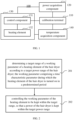
- FIG. 1 is a power control system 100 for a blower provided by an embodiment of the present application. As shown in FIG. 1 , the system at least includes: a calibration terminal 110, a power acquisition component 120 and a hair dryer 130.
- the power acquisition component 120 is used to acquire power parameters of the hair dryer 130.
- the power parameters include the whole machine power of the hair dryer 130.
- the power parameters include the sum of the powers of each component in the hair dryer 130 when working.
- the power acquisition component 120 may be a power sensor or a power meter, etc. This embodiment does not limit the device type of the power acquisition component 120.
- the power acquisition component 120 may be part of the calibration terminal 110; or, the power acquisition component 120 is an independent device from the calibration terminal 110.
- the hair dryer 130 includes a control component 131 and a heating element 132.
- the control component 131 is in communication with the heating element 132.
- the control component 131 is used to control the hair dryer 130, such as: controlling the start and stop of the hair dryer 130, the heating temperature of the heating element 132, the turning on and off of the heating element 132, and so on.
- the control component 131 is a printed circuit board (PCB) of the hair dryer 130.
- the heating element 132 is used to heat the air flowing through the hair dryer 130.
- the heating element 132 may be a heating wire.
- the number of heating wires may be one or more, and the implementation manner of the heating element 132 is not limited in this embodiment.
- the calibration terminal 110 is used for power calibration of the hair dryer 130.
- the calibration terminal 110 may be a computer, a mobile phone, a tablet computer, or a notebook computer, etc. This embodiment does not limit the device type of the calibration terminal 110.
- the calibration terminal 110 When performing power calibration, the calibration terminal 110 is connected in communication with the power acquisition component 120 and the control component 131, respectively.
- the control component 131 in the hair dryer 130 By controlling the control component 131 in the hair dryer 130, the heating element 132 can be controlled to work.
- the power calibration process of the calibration terminal 110 includes: obtaining a power acquired by the power acquisition component 120 and a working parameter of the heating element 132 when the hair dryer 130 is working; and establishing a first correspondence relationship between the power and the working parameter. After that, the calibration terminal 110 stores the first correspondence relationship to the hair dryer 130.
- the working parameter includes a time characteristic parameter when the heating element 131 of the hair dryer 130 is turned on in a predetermined period.
- the working parameter is used to indicate at which time the heating element 131 is turned on and at which time it is turned off within the predetermined period.
- the time characteristic parameter is the number of half waves at which the heating element 131 is turned on.
- the predetermined period includes a plurality of half waves.
- a half wave refers to a half waveform in a sinusoidal voltage signal that powers the heating element 131.
- a voltage at a start position of the half waveform is 0V and a voltage at an end position is 0V.
- the power of the hair dryer 130 when working includes a target power range.
- the first correspondence relationship includes a correspondence relationship between the target power range and the target range of the working parameter.
- the target power range is stored in the calibration terminal 110 in advance.
- the target power ranges corresponding to different gears are different.
- the target power range corresponding to a first gear is [P1, P1']
- the target power range corresponding to a second gear is [P2, P2']
- the target power range corresponding to a third gear is [P3, P3'].
- the target power range is determined based on a rated power corresponding to each gear. For example, if the rated power is 100W, a corresponding target power range can be [90W, 110W].
- the power control system 100 for the hair dryer further includes a temperature acquisition component 140.
- the temperature acquisition component 140 is used to acquire an output air temperature of the hair dryer 130.
- the temperature acquisition component 140 may be a temperature measuring element such as a thermocouple or a thermistor, and the implementation manner of the temperature acquisition component 140 is not limited in this embodiment.
- the temperature acquisition component 140 is connected in communication with the calibration terminal 110.
- the process of power calibration performed by the calibration terminal 110 further includes: acquiring a corresponding outlet air temperature when the hair dryer 130 works according to the working parameter of the heating element 132; and establishing a second correspondence relationship between the working parameter and the outlet air temperature. After that, the calibration terminal 110 stores the second correspondence relationship to the hair dryer 130.
- the outlet air temperature when the hair dryer works includes a target temperature range.
- the second correspondence relationship includes a correspondence relationship between the target temperature range and the target range of the working parameter.
- the target temperature range is stored in the calibration terminal 110 in advance.
- the target temperature ranges corresponding to different gears are different.
- the target power range corresponding to a first gear is [T1, T1']
- the target power range corresponding to a second gear is [T2, T2']
- the target power range corresponding to a third gear is [T3, T3'].
- the hair dryer 130 is used to: determine a target range of a working parameter of a heating element of the hair dryer according to a target power range of the hair dryer 130; the working parameter including a time characteristic parameter during which the heating element of the hair dryer is turned on in a predetermined period; and control the working parameter of the heating element to be kept within the target range, so that a power of the hair dryer is kept within the target power range.
- determining the target range of the working parameter of the heating element of the hair dryer according to the target power range of the hair dryer includes: acquiring a first correspondence relationship between a pre-established working parameter and the power of the hair dryer; and obtaining the target range of the working parameter by calculation according to the target power range and the first correspondence relationship.
- determining the target range of the working parameter of the heating element corresponding to the target power range includes: acquiring a first correspondence relationship between a pre-established working parameter and the power of the hair dryer; acquiring a second correspondence relationship between the pre-established working parameter and an outlet air temperature of the hair dryer; and obtaining the target range of the working parameter of the heating element by calculation, according to the target power range of the hair dryer, a target temperature range of the outlet air temperature, the first correspondence relationship, and the second correspondence relationship.
- FIG. 2 is a power control method of a hair dryer provided by an embodiment of the present application. This embodiment is described by taking the method applied to the power control system 100 of the hair dryer shown in FIG. 1 as an example. The method includes at least the following steps:
- Step 201 determining a target range of a working parameter of a heating element of the hair dryer according to a target power range of the hair dryer; the working parameter including a time characteristic parameter during which the heating element of the hair dryer is turned on in a predetermined period.
- the target power range is determined based on the rated power of the hair dryer.
- the target power ranges corresponding to different gears are different.
- the hair dryer determines the target range of the working parameter of the heating element of the hair dryer according to the target power range of the hair dryer, includes: acquiring a first correspondence relationship between a pre-established working parameter and the power of the hair dryer; and obtaining the target range of the working parameter by calculation according to the target power range and the first correspondence relationship.
- the first correspondence relationship in the hair dryer is established in the following manners: controlling an operation of the hair dryer; adjusting the working parameter during the operation; recording a numerical value of the working parameter during an adjustment process, and detecting a power value corresponding to the numerical value of the working parameter; and obtaining the first correspondence relationship by calculation according to the numerical value of the working parameter and the power value.
- determining the target range of the working parameter of the heating element corresponding to the target power range includes: acquiring a first correspondence relationship between a pre-established working parameter and the power of the hair dryer; acquiring a second correspondence relationship between the pre-established working parameter and an outlet air temperature of the hair dryer; and obtaining the target range of the working parameter of the heating element by calculation, according to the target power range of the hair dryer, a target temperature range of the outlet air temperature, the first correspondence relationship, and the second correspondence relationship.
- the second correspondence relationship in the hair dryer is established in the following manners: controlling an operation of the hair dryer; adjusting the working parameter during the operation; recording a numerical value of the working parameter during an adjustment process, and detecting a temperature value of the outlet air temperature corresponding to the numerical value of the working parameter; and obtaining the second correspondence relationship by calculation according to the working parameter and the temperature value.
- obtaining the target range of the working parameter of the heating element by calculation, according to the target power range of the hair dryer, the target temperature range of the outlet air temperature, the first correspondence relationship, and the second correspondence relationship includes: obtaining a first target range of the working parameter of the heating element by calculation, according to the target power range and the first correspondence relationship; obtaining a second target range of the working parameter of the heating element by calculation, according to the target temperature range and the second correspondence relationship; and using an intersection of the first target range and the second target range as the target range of the working parameter of the heating element.
- Step 202 controlling the working parameter of the heating element to be kept within the target range, so that a power of the hair dryer is kept within the target power range.
- the working parameter includes the number of half waves during which the heating element of the hair dryer is turned on in the predetermined period; wherein the predetermined period includes a plurality of the half waves; and correspondingly, controlling the working parameter of the heating element to be kept within the target range, includes: by controlling on or off of the heating element, keeping the number of half waves during which the heating element is turned on within the target range in the predetermined period; wherein one or more spaced half waves exist between part or all of adjacent halves where the heating element is turned on.
- the half wave refers to a half waveform in a sinusoidal voltage signal that powers the heating element.
- a voltage at a start position of the half waveform is 0V and a voltage at an end position is 0V.
- the target range of the working parameter of the heating element of the hair dryer according to the target power range of the hair dryer; the working parameter including the time characteristic parameter during which the heating element of the hair dryer is turned on in a predetermined period; and by controlling the working parameter of the heating element to be kept within the target range, so that the power of the hair dryer is kept within the target power range, it can solve the problem that the actual working powers of different hair dryers working in the same gear are different due to the differences among the different hair dryers.
- pre-determining the working parameter of the heating element when the hair dryer is operating in the target power range operating according to the working parameter can ensure that the power of the hair dryer remains within the target power range. In this way, the power ranges of different hair dryers working in the same gear can be made consistent without adjusting the differences among the hair dryers of the same model. Therefore, different hair dryers of the same model can be made to work according to the desired power.
- FIG. 3 is a block diagram of a power control device for a hair dryer provided by an embodiment of the present application.
- the device at least includes the following modules: a computing unit 310 and a control unit 320.
- the computing unit 310 is configured to determine a target range of a working parameter of a heating element of the hair dryer according to a target power range of the hair dryer.
- the working parameter includes a time characteristic parameter during which the heating element of the hair dryer is turned on in a predetermined period.
- the control unit 320 is configured to control the working parameter of the heating element to be kept within the target range, so that a power of the hair dryer is kept within the target power range.
- the computing unit is further configured to acquire a first correspondence relationship between a pre-established working parameter and the power of the hair dryer; and obtain the target range of the working parameter by calculation according to the target power range and the first correspondence relationship.
- the working parameter includes the number of half waves during which the heating element of the hair dryer is turned on in the predetermined period; wherein the predetermined period includes a plurality of the half waves; and correspondingly, the control unit is further configured to: keep the number of half waves during which the heating element is turned on within the target range in the predetermined period, by controlling on or off of the heating element; wherein one or more spaced half waves exist between part or all of adjacent halves where the heating element is turned on.
- the computing unit is further configured to acquire a first correspondence relationship between a pre-established working parameter and the power of the hair dryer; acquire a second correspondence relationship between the pre-established working parameter and an outlet air temperature of the hair dryer; and obtain the target range of the working parameter of the heating element by calculation, according to the target power range of the hair dryer, a target temperature range of the outlet air temperature, the first correspondence relationship, and the second correspondence relationship.
- the first correspondence relationship includes establishing in following manners:
- the second correspondence relationship includes establishing in following manners:
- obtaining the target range of the working parameter of the heating element by calculation, according to the target power range of the hair dryer, the target temperature range of the outlet air temperature, the first correspondence relationship, and the second correspondence relationship includes:
- the power control device of the hair dryer provided in the above embodiment performs the power control of the hair dryer
- only the division of the above functional modules is used as an example for illustration.
- the above-mentioned functions can be assigned to different function modules as required. That is, the internal structure of the power control device of the hair dryer is divided into different functional modules to complete all or part of the functions described above.
- the power control device for the hair dryer provided in the above embodiment and the embodiment of the power control method for the hair dryer belong to the same concept, and the specific implementation process is detailed in the method embodiment, which will not be repeated here.
- FIG. 4 is a block diagram of a power control device of a hair dryer provided by an embodiment of the present application.
- the device includes at least a processor 401 and a memory 402.
- the processor 401 may include one or more processing cores, such as a 4-core processor, an 8-core processor, and the like.
- the processor 401 may be implemented in at least one hardware form among DSP (Digital Signal Processing), FPGA (Field-Programmable Gate Array), and PLA (Programmable Logic Array).
- the memory 402 may include one or more computer-readable storage medium.
- the computer-readable storage medium may be non-transitory.
- the memory 402 may also include high-speed random access memory, as well as non-volatile memory, such as one or more disk storage devices, flash storage devices.
- a non-transitory computer-readable storage medium in the memory 402 is used to store at least one instruction. The at least one instruction is loaded and executed by the processor 401 to implement the power control method of the hair dryer provided by the method embodiments of the present application.
- the power control device of the hair dryer may also optionally include: a peripheral device port and at least one peripheral device.
- the processor 401, the memory 402 and the peripheral device port can be connected through a BUS or a signal line.
- Each peripheral device can be connected to the peripheral device port through the BUS, the signal line or a circuit board.
- the peripheral devices include, but are not limited to, radio frequency circuits, touch screens, audio circuits, probes and power supplies etc.
- the power control device of the hair dryer may further include fewer or more components, which is not limited in this embodiment.
- the present application further provides a computer-readable storage medium in which a program is stored.
- the program is loaded and executed by the processor to implement the power control method of the hair dryer of the above method embodiments.
- the present application also provides a computer product.
- the computer product includes a computer-readable storage medium in which a program is stored.
- the program is loaded and executed by the processor to implement the power control method of the hair dryer of the above method embodiments.
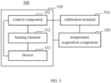
- FIG. 5 is a temperature calibration system 500 for the hair dryer provided by an embodiment of the present application.
- the system at least includes: a calibration terminal 510, a temperature acquisition component 520 and a blower 530.
- the temperature acquisition component 520 is used to acquire an outlet air temperature of the hair dryer 530 and send the outlet air temperature to the calibration terminal 510.
- the temperature acquisition component 520 may be a temperature measuring element such as a thermocouple or a thermistor, and the implementation manner of the temperature acquisition component 520 is not limited in this embodiment.
- the temperature acquisition component 520 may be part of the calibration terminal 510; or, the temperature acquisition component 520 is an independent device from the calibration terminal 510.
- the hair dryer 530 includes a control component 531, a heating element 532 and a blower 533.
- the control component 531 is connected in communication with the heating element 532 and the blower 533, respectively, and controls the operation of the heating element 532 and the blower 533 through the communication connection.
- the control component 531 may be a printed circuit board (PCB) of the hair dryer 530.
- the blower 533 is used to generate an airflow in the hair dryer 530.
- a flow direction of the airflow is to enter from an air inlet of the hair dryer 530 and discharge from an air outlet of the hair dryer 530.
- the calibration terminal 510 is used to perform temperature calibration on the temperature control parameter in the hair dryer 530.
- the calibration terminal 510 may be a computer, a mobile phone, a tablet computer, a notebook computer, or the like, and the device type of the calibration terminal 510 is not limited in this embodiment.
- the calibration terminal 510 When performing temperature calibration, the calibration terminal 510 is connected in communication with the temperature acquisition component 520 and the control component 531, respectively; and the calibration terminal 510 controls the heating element 532 and/or the blower 533 to work by controlling the control component 531 in the hair dryer 530.
- the process of the temperature calibration performed by the calibration terminal 510 includes: controlling an operation of the hair dryer 530; detecting an outlet air temperature of the hair dryer 503 in real time during the operation; and determining a measured value of a temperature control parameter of the hair dryer 530 as a calibration value of the temperature control parameter, when the outlet air temperature is a target temperature.
- the target temperature is pre-stored in the calibration terminal 510, and the value of the target temperature is uniformly calibrated for the hair dryers 530 of the same model.
- the target temperatures corresponding to different gears are different.
- the target temperature corresponding to a first gear is T1
- the target temperature corresponding to a second gear is T2
- the target temperature corresponding to a third gear is T3.
- the temperature control parameter includes a heating temperature of the heating element 532 and/or a rotation speed of the blower 533; or, the temperature control parameter includes the number of half waves during which the heating element 532 is turned on in the control period and/or the rotation speed of the blower 533.
- This embodiment does not limit the specific content of the temperature control parameter.
- the system for calibrating the temperature control parameter for the hair dryer 530 provided in this embodiment can keep the outlet air temperature of different hair dryers 530 working in the same gear consistent without adjusting the differences among the hair dryers 530 of the same model. Therefore, the different hair dryers 530 of the same model can all achieve desired working effects.
- FIG. 6 is a flowchart of a method for calibrating a temperature control parameter of a hair dryer provided by an embodiment of the present application. This embodiment is described by taking as an example that the method is applied to the temperature calibration system 500 of the hair dryer shown in FIG. 5 , and the execution subject of each step is the calibration terminal 510 in the system. The method includes at least the following steps:
- Step 601 controlling an operation of the hair dryer.
- An operating state of the hair dryer is controlled so that an outlet air temperature reaches a target temperature.
- the calibration terminal adjusts the outlet air temperature of the hair dryer by controlling a working state of a heating element and/or a blower of the hair dryer.
- adjusting the outlet air temperature of the hair dryer by controlling the working state of the heating element and/or the blower of the hair dryer includes: adjusting the outlet air temperature by controlling the number of half waves during which the heating element is turned on in a preset control period; wherein the control period includes a plurality of the half waves; and/or adjusting the outlet air temperature by controlling the rotation speed of the blower.
- the half wave refers to a half waveform in a sinusoidal voltage signal that powers the heating element.
- a voltage at a start position of the half waveform is 0V and a voltage at an end position is 0V.
- controlling the working state of the heating element and/or the blower of the hair dryer includes: sending an initial control signal to a control component in the hair dryer, the initial control signal being used to trigger the control component to control the hair dryer to work according to an initial temperature control parameters; obtaining the current outlet air temperature corresponding to the initial control signal acquired by the temperature acquisition component; when the current outlet air temperature is inconsistent with the target temperature, adjusting the current temperature control parameter to obtain the current outlet air temperature corresponding to the parameter adjustment; when the current outlet air temperature is inconsistent with the target temperature, performing the step of adjusting the current temperature control parameter again to obtain the current outlet air temperature corresponding to the parameter adjustment; when the current outlet air temperature is consistent with the target temperature, determining that the outlet air temperature reaches the target temperature.
- the temperature control parameter (including the initial temperature control parameter) includes the number of half waves and/or the rotation speed of the blower, during which the heating element is turned on in the control period.
- the initial temperature control parameter and the target temperature are pre-stored in the calibration terminal.
- the initial temperature control parameter is the temperature control parameter originally calibrated in the hair dryer.
- the target temperature is the desired outlet air temperature of the hair dryer in the current working state.
- the working state of the hair dryer includes at least two gears. Different gears correspond to different target temperatures.
- the initial temperature control parameters corresponding to different gears are different. For example, the target temperature corresponding to a first gear is T1, and the corresponding initial heating temperature is A; the target temperature corresponding to a second gear is T2, and the corresponding initial heating temperature is B; the target temperature corresponding to a third gear is T3, and the corresponding initial heating temperature is C.
- Step 602 during the operating process, detecting the outlet air temperature of the hair dryer in real time.
- Detecting the outlet air temperature of the hair dryer in real time includes: detecting a temperature in front of an air outlet of the hair dryer at a specific distance from the air outlet in real time as the outlet air temperature.
- the temperature acquisition component connected in communication with the calibration terminal acquires the outlet air temperature in front of the air outlet of the hair dryer in real time, and sends the outlet air temperature to the calibration terminal.
- the calibration terminal receives the outlet air temperature acquired in real time.
- Step 603 when the outlet air temperature is the target temperature, determining a measured value of the temperature control parameter of the hair dryer as a calibration value of the temperature control parameter.
- the calibration value is stored in the target memory, and a correspondence relationship between the calibration value and the target temperature is stored.
- the hair dryer includes multiple working modes, for example, including a first working mode corresponding to a first gear and a second working mode corresponding to a second gear.
- the target temperature corresponds to the working mode of the hair dryer.
- the method further includes: storing the calibration value in the target memory, and storing the correspondence relationship between the calibration value and the working mode.
- the method for calibrating the temperature control parameter of the hair dryer provided in this embodiment can solve the problem that the outlet air temperatures of different hair dryers may be different under the same temperature control parameter due to slight differences among the different hair dryers when the temperature control parameters of the hair dryers are uniformly calibrated. Since the temperature control parameters of different hair dryers are calibrated according to the uniform outlet air temperature, the outlet air temperatures of different hair dryers can be kept consistent under the same temperature control parameter without adjusting the differences among the hair dryers of the same model. Therefore, different hair dryers of the same model can all achieve desired working effects.
- FIG. 7 is a block diagram of a device for calibrating a temperature control parameter of a hair dryer provided by an embodiment of the present application. This embodiment is described by taking the device applied to the system for calibrating the temperature control parameter of the hair dryer shown in FIG. 5 as an example.
- the device at least includes the following modules: a detection unit 710 and a calibration unit 720.
- the detection unit 710 is configured to detect an outlet air temperature of the hair dryer in real time during an operation of the hair dryer.
- the calibration unit 720 is in communication with the hair dryer.
- the calibration unit is configured to send a control instruction to the hair dryer to control the operation of the hair dryer, and is configured to determine a measured value of a temperature control parameter of the hair dryer as a calibration value of the temperature control parameter, when the outlet air temperature is a target temperature.
- the detection unit 710 is further configured to: control an operating state of the hair dryer so that the outlet air temperature reaches the target temperature.
- the detection unit 710 is further configured to: detect a temperature in front of an air outlet of the hair dryer at a specific distance from the air outlet in real time as the outlet air temperature.
- the detection unit 710 is further configured to: store the calibration value in a target memory, and store a correspondence relationship between the calibration value and the target temperature.
- the target temperature corresponds to a working mode of the hair dryer.
- the detection unit 710 is further configured to: store the calibration value in a target memory, and store a correspondence relationship between the calibration value and the working mode.
- the detection unit 710 is further configured to: adjust the outlet air temperature of the hair dryer by controlling a working state of a heating element and/or a blower of the hair dryer.
- the detection unit 710 is further configured to: adjust the outlet air temperature by controlling the number of half waves during which the heating element is turned on in a preset control period; wherein the control period includes a plurality of the half waves.
- the device for calibrating a temperature control parameter of the hair dryer provided in the above embodiment performs the temperature control parameter calibration of the hair dryer
- only the division of the above functional modules is used as an example for illustration.
- the above-mentioned functions can be assigned to different function modules as required. That is, the internal structure of the device for calibrating a temperature control parameter of the hair dryer is divided into different functional modules, so as to complete all or part of the functions described above.
- the device for calibrating the temperature control parameter of the hair dryer provided by the above embodiment and the embodiment of the method for calibrating the temperature control parameter of the hair dryer belong to the same concept.
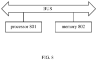
- FIG. 8 is a block diagram of a device for calibrating a temperature control parameter of a hair dryer provided by an embodiment of the present application.
- the device includes at least a processor 801 and a memory 802.
- the processor 801 may include one or more processing cores, such as a 4-core processor, an 8-core processor, and the like.
- the processor 801 may be implemented in at least one hardware form among DSP (Digital Signal Processing), FPGA (Field-Programmable Gate Array), and PLA (Programmable Logic Array).
- the processor 801 may also include a main processor and a co-processor.
- the main processor is a processor for processing data in a wake-up state, and is also called a CPU (Central Processing Unit).
- the co-processor is a low-power processor for processing data in a standby state.
- the memory 802 may include one or more computer-readable storage medium.
- the computer-readable storage medium may be non-transitory.
- the memory 802 may also include high-speed random access memory, as well as non-volatile memory, such as one or more disk storage devices, flash storage devices.
- a non-transitory computer-readable storage medium in the memory 802 is used to store at least one instruction. The at least one instruction is loaded and executed by the processor 801 to implement the method for calibrating the temperature control parameter of the hair dryer provided in the method embodiment of the present application.
- the device for calibrating the temperature control parameter of the hair dryer may also optionally include: a peripheral device port and at least one peripheral device.
- the processor 801, the memory 802 and the peripheral device port can be connected through a BUS or a signal line.
- Each peripheral device can be connected to the peripheral device port through the BUS, the signal line or a circuit board.
- the peripheral devices include, but are not limited to, radio frequency circuits, touch screens, audio circuits, probes and power supplies etc.
- the device for calibrating the temperature control parameter of the hair dryer may also include fewer or more components, which is not limited in this embodiment.
- the present application further provides a computer-readable storage medium in which a program is stored.
- the program is loaded and executed by the processor to implement the method for calibrating the temperature control parameter of the hair dryer according to the above method embodiments.
- the present application also provides a computer product.
- the computer product includes a computer-readable storage medium in which a program is stored.
- the program is loaded and executed by the processor to implement the method for calibrating the temperature control parameter of the hair dryer according to the above method embodiments.
Landscapes
- Engineering & Computer Science (AREA)
- Physics & Mathematics (AREA)
- General Physics & Mathematics (AREA)
- Automation & Control Theory (AREA)
- Health & Medical Sciences (AREA)
- Artificial Intelligence (AREA)
- Computer Vision & Pattern Recognition (AREA)
- Evolutionary Computation (AREA)
- Medical Informatics (AREA)
- Software Systems (AREA)
- Cleaning And Drying Hair (AREA)
- Control Of Temperature (AREA)
Abstract
Description
- The present application relates to a power control method, a method for calibrating a temperature control parameter and a device for a hair dryer, which belongs to the technical field of computers.
- Hair dryers are mainly used for drying and shaping of hair. The hair dryer usually includes a heating wire and a blower. When energized, the heating wire will generate heat, and the blower will drive an airflow to flow through the heating wire and output hot air from an air outlet.
- Generally, a power of the hair dryer and a temperature of the heating wire corresponding to each gear in the hair dryer are uniformly calibrated. However, due to the differences among different hair dryers, it will lead to a problem that the actual working power of different hair dryers working in the same gear is different, and a problem that the temperature of the same heating wire and the outlet air temperature corresponding to different hair dryers are different.
- The present application provides a power control method, a device and a storage medium for a hair dryer, which can solve the problems that due to the differences among different hair dryers, the actual working powers of the different hair dryers working in the same gear are different; and for the temperature of the same heating wire, the outlet air temperatures corresponding to the different hair dryers are different. The present application provides the following technical solutions:
- A first aspect provides a power control method for a hair dryer. The method includes:
- determining a target range of a working parameter of a heating element of the hair dryer according to a target power range of the hair dryer; the working parameter including a time characteristic parameter during which the heating element of the hair dryer is turned on in a predetermined period; and
- controlling the working parameter of the heating element to be kept within the target range, so that a power of the hair dryer is kept within the target power range.
- Optionally, determining the target range of the working parameter of the heating element of the hair dryer according to the target power range of the hair dryer, includes:
- acquiring a first correspondence relationship between a pre-established working parameter and the power of the hair dryer; and
- obtaining the target range of the working parameter by calculation according to the target power range and the first correspondence relationship.
- Optionally, the working parameter includes the number of half waves during which the heating element of the hair dryer is turned on in the predetermined period; wherein the predetermined period includes a plurality of the half waves; and correspondingly, controlling the working parameter of the heating element to be kept within the target range, includes:
by controlling on or off of the heating element, keeping the number of half waves during which the heating element is turned on within the target range in the predetermined period; wherein one or more spaced half waves exist between part or all of adjacent halves where the heating element is turned on. - Optionally, determining the target range of the working parameter of the heating element corresponding to the target power range, includes:
- acquiring a first correspondence relationship between a pre-established working parameter and the power of the hair dryer;
- acquiring a second correspondence relationship between the pre-established working parameter and an outlet air temperature of the hair dryer; and
- obtaining the target range of the working parameter of the heating element by calculation, according to the target power range of the hair dryer, a target temperature range of the outlet air temperature, the first correspondence relationship, and the second correspondence relationship.
- Optionally, the first correspondence relationship includes establishing in following manners:
- controlling an operation of the hair dryer;
- adjusting the working parameter during the operation;
- recording a numerical value of the working parameter during an adjustment process, and detecting a power value corresponding to the numerical value of the working parameter; and
- obtaining the first correspondence relationship by calculation according to the numerical value of the working parameter and the power value.
- Optionally, the second correspondence relationship includes establishing in following manners:
- controlling an operation of the hair dryer;
- adjusting the working parameter during the operation;
- recording a numerical value of the working parameter during an adjustment process, and detecting a temperature value of the outlet air temperature corresponding to the numerical value of the working parameter; and
- obtaining the second correspondence relationship by calculation according to the working parameter and the temperature value.
- Optionally, obtaining the target range of the working parameter of the heating element by calculation, according to the target power range of the hair dryer, the target temperature range of the outlet air temperature, the first correspondence relationship, and the second correspondence relationship, includes:
- obtaining a first target range of the working parameter of the heating element by calculation, according to the target power range and the first correspondence relationship;
- obtaining a second target range of the working parameter of the heating element by calculation, according to the target temperature range and the second correspondence relationship; and
- using an intersection of the first target range and the second target range as the target range of the working parameter of the heating element.
- A second aspect provides a power control device for a hair dryer. The device includes:
- a computing unit, configured to determine a target range of a working parameter of a heating element of the hair dryer according to a target power range of the hair dryer; the working parameter including a time characteristic parameter during which the heating element of the hair dryer is turned on in a predetermined period; and
- a control unit, configured to control the working parameter of the heating element to be kept within the target range, so that a power of the hair dryer is kept within the target power range.
- Optionally, the computing unit is further configured to acquire a first correspondence relationship between a pre-established working parameter and the power of the hair dryer; and obtain the target range of the working parameter by calculation according to the target power range and the first correspondence relationship.
- Optionally, the working parameter includes the number of half waves during which the heating element of the hair dryer is turned on in the predetermined period; wherein the predetermined period includes a plurality of the half waves; and correspondingly, the control unit is further configured to:
keep the number of half waves during which the heating element is turned on within the target range in the predetermined period, by controlling on or off of the heating element; wherein one or more spaced half waves exist between part or all of adjacent halves where the heating element is turned on. - Optionally, the computing unit is further configured to acquire a first correspondence relationship between a pre-established working parameter and the power of the hair dryer; acquire a second correspondence relationship between the pre-established working parameter and an outlet air temperature of the hair dryer; and obtain the target range of the working parameter of the heating element by calculation, according to the target power range of the hair dryer, a target temperature range of the outlet air temperature, the first correspondence relationship, and the second correspondence relationship.
- Optionally, the first correspondence relationship includes establishing in following manners:
- controlling an operation of the hair dryer;
- adjusting the working parameter during the operation;
- recording a numerical value of the working parameter during an adjustment process, and detecting a power value corresponding to the numerical value of the working parameter; and
- obtaining the first correspondence relationship by calculation according to the numerical value of the working parameter and the power value.
- Optionally, the second correspondence relationship includes establishing in following manners:
- controlling an operation of the hair dryer;
- adjusting the working parameter during the operation;
- recording a numerical value of the working parameter during an adjustment process, and detecting a temperature value of the outlet air temperature corresponding to the numerical value of the working parameter; and
- obtaining the second correspondence relationship by calculation according to the working parameter and the temperature value.
- Optionally, obtaining the target range of the working parameter of the heating element by calculation, according to the target power range of the hair dryer, the target temperature range of the outlet air temperature, the first correspondence relationship, and the second correspondence relationship, includes:
- obtaining a first target range of the working parameter of the heating element by calculation, according to the target power range and the first correspondence relationship;
- obtaining a second target range of the working parameter of the heating element by calculation, according to the target temperature range and the second correspondence relationship; and
- using an intersection of the first target range and the second target range as the target range of the working parameter of the heating element.
- The beneficial effects of the first aspect and the second aspect of the present application are: by determining the target range of the working parameter of the heating element of the hair dryer according to the target power range of the hair dryer; the working parameter including the time characteristic parameter during which the heating element of the hair dryer is turned on in a predetermined period; and by controlling the working parameter of the heating element to be kept within the target range, so that the power of the hair dryer is kept within the target power range, it can solve the problem that the actual working powers of different hair dryers working in the same gear are different due to the differences among the different hair dryers. By pre-determining the working parameter of the heating element when the hair dryer is operating in the target power range, operating according to the working parameter can ensure that the power of the hair dryer remains within the target power range. In this way, the power ranges of different hair dryers working in the same gear can be made consistent without adjusting the differences among the hair dryers of the same model. Therefore, different hair dryers of the same model can be made to work according to the desired power.
- A third aspect provides a method for calibrating a temperature control parameter of a hair dryer. The method includes:
- controlling an operation of the hair dryer;
- detecting an outlet air temperature of the hair dryer in real time during the operation; and
- determining a measured value of a temperature control parameter of the hair dryer as a calibration value of the temperature control parameter, when the outlet air temperature is a target temperature.
- Optionally, the method further includes:
storing the calibration value in a target memory, and storing a correspondence relationship between the calibration value and the target temperature. - Optionally, controlling the operation of the hair dryer, includes:
controlling an operating state of the hair dryer so that the outlet air temperature reaches the target temperature. - Optionally, detecting the outlet air temperature of the hair dryer in real time, includes:
detecting a temperature in front of an air outlet of the hair dryer at a specific distance from the air outlet in real time as the outlet air temperature. - Optionally, the target temperature corresponds to a working mode of the hair dryer; correspondingly, the method further includes:
storing the calibration value in a target memory, and storing a correspondence relationship between the calibration value and the working mode. - Optionally, controlling the operating state of the hair dryer so that the outlet air temperature reaches the target temperature, includes:
adjusting the outlet air temperature of the hair dryer by controlling a working state of a heating element and/or a blower of the hair dryer. - Optionally, adjusting the outlet air temperature of the hair dryer by controlling the working state of the heating element and/or the blower of the hair dryer, includes:
adjusting the outlet air temperature by controlling the number of half waves during which the heating element is turned on in a preset control period; wherein the control period includes a plurality of the half waves. - A fourth aspect provides a power control device for a hair dryer. The device includes:
- a computing unit, configured to determine a target range of a working parameter of a heating element of the hair dryer according to a target power range of the hair dryer; the working parameter including a time characteristic parameter during which the heating element of the hair dryer is turned on in a predetermined period; and
- a control unit, configured to control the working parameter of the heating element to be kept within the target range, so that a power of the hair dryer is kept within the target power range.
- Optionally, the computing unit is further configured to acquire a first correspondence relationship between a pre-established working parameter and the power of the hair dryer; and obtain the target range of the working parameter by calculation according to the target power range and the first correspondence relationship.
- Optionally, the working parameter includes the number of half waves during which the heating element of the hair dryer is turned on in the predetermined period; wherein the predetermined period includes a plurality of the half waves; and correspondingly, the control unit is further configured to:
keep the number of half waves during which the heating element is turned on within the target range in the predetermined period, by controlling on or off of the heating element; wherein one or more spaced half waves exist between part or all of adjacent halves where the heating element is turned on. - Optionally, the device includes:
- a detection unit, configured to detect an outlet air temperature of the hair dryer in real time during an operation of the hair dryer; and
- a calibration unit in communication with the hair dryer, the calibration unit being configured to send a control instruction to the hair dryer to control the operation of the hair dryer, and being configured to determine a measured value of a temperature control parameter of the hair dryer as a calibration value of the temperature control parameter, when the outlet air temperature is a target temperature.
- Optionally, the detection unit is further configured to:
control an operating state of the hair dryer so that the outlet air temperature reaches the target temperature. - Optionally, the detection unit is further configured to:
detect a temperature in front of an air outlet of the hair dryer at a specific distance from the air outlet in real time as the outlet air temperature. - The beneficial effects of the third aspect and the fourth aspect of the present application are: by controlling an operation of the hair dryer; by detecting an outlet air temperature of the hair dryer in real time during the operation; and by determining a measured value of a temperature control parameter of the hair dryer as a calibration value of the temperature control parameter, when the outlet air temperature is a target temperature; it can solve the problem that the outlet air temperatures of different hair dryers may be different under the same temperature control parameter due to slight differences among the different hair dryers when the temperature control parameters of the hair dryers are uniformly calibrated. Since the temperature control parameters of different hair dryers are calibrated according to the uniform outlet air temperature, the outlet air temperatures of different hair dryers can be kept consistent under the same temperature control parameter without adjusting the differences among the hair dryers of the same model. Therefore, different hair dryers of the same model can all achieve desired working effects.
- The above description is only an overview of the technical solutions of the present application. In order to have a clearer understanding of the technical means of the present application and to implement them in accordance with the contents of the specification, the following detailed description is given with reference to the preferred embodiments of the present application and the accompanying drawings.
-
-
FIG. 1 is a schematic structural diagram of a power control system for a hair dryer provided by an embodiment of the present application; -
FIG. 2 is a flowchart of a power control method for a hair dryer provided by an embodiment of the present application; -
FIG. 3 is a block diagram of a power control device for a hair dryer provided by an embodiment of the present application; -
FIG. 4 is a block diagram of a power control device for a hair dryer provided by another embodiment of the present application; -
FIG. 5 is a schematic structural diagram of a temperature calibration system for a hair dryer provided by an embodiment of the present application; -
FIG. 6 is a flowchart of a method for calibrating a temperature of a hair dryer provided by an embodiment of the present application; -
FIG. 7 is a block diagram of a temperature calibration device for a hair dryer provided by an embodiment of the present application; and -
FIG. 8 is a block diagram of a device for calibrating a temperature of a hair dryer provided by another embodiment of the present application. - The specific implementations of the present application will be described in further detail below with reference to the accompanying drawings and embodiments. The following embodiments are used to illustrate the present application, but are not intended to limit the scope of the present application.
-
FIG. 1 is apower control system 100 for a blower provided by an embodiment of the present application. As shown inFIG. 1 , the system at least includes: acalibration terminal 110, apower acquisition component 120 and ahair dryer 130. - The
power acquisition component 120 is used to acquire power parameters of thehair dryer 130. Wherein, the power parameters include the whole machine power of thehair dryer 130. In other words, the power parameters include the sum of the powers of each component in thehair dryer 130 when working. - Optionally, the
power acquisition component 120 may be a power sensor or a power meter, etc. This embodiment does not limit the device type of thepower acquisition component 120. - Optionally, the
power acquisition component 120 may be part of thecalibration terminal 110; or, thepower acquisition component 120 is an independent device from thecalibration terminal 110. - The
hair dryer 130 includes acontrol component 131 and aheating element 132. Thecontrol component 131 is in communication with theheating element 132. - The
control component 131 is used to control thehair dryer 130, such as: controlling the start and stop of thehair dryer 130, the heating temperature of theheating element 132, the turning on and off of theheating element 132, and so on. In one example, thecontrol component 131 is a printed circuit board (PCB) of thehair dryer 130. - The
heating element 132 is used to heat the air flowing through thehair dryer 130. Optionally, theheating element 132 may be a heating wire. The number of heating wires may be one or more, and the implementation manner of theheating element 132 is not limited in this embodiment. - The
calibration terminal 110 is used for power calibration of thehair dryer 130. Optionally, thecalibration terminal 110 may be a computer, a mobile phone, a tablet computer, or a notebook computer, etc. This embodiment does not limit the device type of thecalibration terminal 110. - When performing power calibration, the
calibration terminal 110 is connected in communication with thepower acquisition component 120 and thecontrol component 131, respectively. By controlling thecontrol component 131 in thehair dryer 130, theheating element 132 can be controlled to work. - The power calibration process of the
calibration terminal 110 includes: obtaining a power acquired by thepower acquisition component 120 and a working parameter of theheating element 132 when thehair dryer 130 is working; and establishing a first correspondence relationship between the power and the working parameter. After that, thecalibration terminal 110 stores the first correspondence relationship to thehair dryer 130. - Wherein, the working parameter includes a time characteristic parameter when the
heating element 131 of thehair dryer 130 is turned on in a predetermined period. In other words, the working parameter is used to indicate at which time theheating element 131 is turned on and at which time it is turned off within the predetermined period. - In one example, the time characteristic parameter is the number of half waves at which the
heating element 131 is turned on. Wherein, the predetermined period includes a plurality of half waves. A half wave refers to a half waveform in a sinusoidal voltage signal that powers theheating element 131. A voltage at a start position of the half waveform is 0V and a voltage at an end position is 0V. - The power of the
hair dryer 130 when working includes a target power range. In this way, the first correspondence relationship includes a correspondence relationship between the target power range and the target range of the working parameter. - The target power range is stored in the
calibration terminal 110 in advance. Optionally, when thehair dryer 130 includes at least two gears, the target power ranges corresponding to different gears are different. - For example, the target power range corresponding to a first gear is [P1, P1'], the target power range corresponding to a second gear is [P2, P2'], and the target power range corresponding to a third gear is [P3, P3'].
- Optionally, the target power range is determined based on a rated power corresponding to each gear. For example, if the rated power is 100W, a corresponding target power range can be [90W, 110W].
- Optionally, the
power control system 100 for the hair dryer further includes atemperature acquisition component 140. Thetemperature acquisition component 140 is used to acquire an output air temperature of thehair dryer 130. Optionally, thetemperature acquisition component 140 may be a temperature measuring element such as a thermocouple or a thermistor, and the implementation manner of thetemperature acquisition component 140 is not limited in this embodiment. Thetemperature acquisition component 140 is connected in communication with thecalibration terminal 110. - At this time, the process of power calibration performed by the
calibration terminal 110 further includes: acquiring a corresponding outlet air temperature when thehair dryer 130 works according to the working parameter of theheating element 132; and establishing a second correspondence relationship between the working parameter and the outlet air temperature. After that, thecalibration terminal 110 stores the second correspondence relationship to thehair dryer 130. - Wherein, the outlet air temperature when the hair dryer works includes a target temperature range. In this way, the second correspondence relationship includes a correspondence relationship between the target temperature range and the target range of the working parameter.
- The target temperature range is stored in the
calibration terminal 110 in advance. Optionally, when thehair dryer 130 includes at least two gears, the target temperature ranges corresponding to different gears are different. - For example: the target power range corresponding to a first gear is [T1, T1']; the target power range corresponding to a second gear is [T2, T2']; and the target power range corresponding to a third gear is [T3, T3'].
- Optionally, in the present application, the
hair dryer 130 is used to: determine a target range of a working parameter of a heating element of the hair dryer according to a target power range of thehair dryer 130; the working parameter including a time characteristic parameter during which the heating element of the hair dryer is turned on in a predetermined period; and control the working parameter of the heating element to be kept within the target range, so that a power of the hair dryer is kept within the target power range. - In one example, determining the target range of the working parameter of the heating element of the hair dryer according to the target power range of the hair dryer, includes: acquiring a first correspondence relationship between a pre-established working parameter and the power of the hair dryer; and obtaining the target range of the working parameter by calculation according to the target power range and the first correspondence relationship.
- In another example, determining the target range of the working parameter of the heating element corresponding to the target power range, includes: acquiring a first correspondence relationship between a pre-established working parameter and the power of the hair dryer; acquiring a second correspondence relationship between the pre-established working parameter and an outlet air temperature of the hair dryer; and obtaining the target range of the working parameter of the heating element by calculation, according to the target power range of the hair dryer, a target temperature range of the outlet air temperature, the first correspondence relationship, and the second correspondence relationship.
- In this embodiment, by pre-determining the working parameter of the heating element when the hair dryer is operating in the target power range, operating according to the working parameter can ensure that the power of the hair dryer remains within the target power range. In this way, the power ranges of different hair dryers working in the same gear can be made consistent without adjusting the differences among the hair dryers of the same model. Therefore, different hair dryers of the same model can be made to work according to the desired power.
-
FIG. 2 is a power control method of a hair dryer provided by an embodiment of the present application. This embodiment is described by taking the method applied to thepower control system 100 of the hair dryer shown inFIG. 1 as an example. The method includes at least the following steps: -
Step 201, determining a target range of a working parameter of a heating element of the hair dryer according to a target power range of the hair dryer; the working parameter including a time characteristic parameter during which the heating element of the hair dryer is turned on in a predetermined period. - Optionally, the target power range is determined based on the rated power of the hair dryer. When the hair dryer includes at least two gears, the target power ranges corresponding to different gears are different.
- In one example, the hair dryer determines the target range of the working parameter of the heating element of the hair dryer according to the target power range of the hair dryer, includes: acquiring a first correspondence relationship between a pre-established working parameter and the power of the hair dryer; and obtaining the target range of the working parameter by calculation according to the target power range and the first correspondence relationship.
- The first correspondence relationship in the hair dryer is established in the following manners: controlling an operation of the hair dryer; adjusting the working parameter during the operation; recording a numerical value of the working parameter during an adjustment process, and detecting a power value corresponding to the numerical value of the working parameter; and obtaining the first correspondence relationship by calculation according to the numerical value of the working parameter and the power value.
- In another example, determining the target range of the working parameter of the heating element corresponding to the target power range, includes: acquiring a first correspondence relationship between a pre-established working parameter and the power of the hair dryer; acquiring a second correspondence relationship between the pre-established working parameter and an outlet air temperature of the hair dryer; and obtaining the target range of the working parameter of the heating element by calculation, according to the target power range of the hair dryer, a target temperature range of the outlet air temperature, the first correspondence relationship, and the second correspondence relationship.
- The second correspondence relationship in the hair dryer is established in the following manners: controlling an operation of the hair dryer; adjusting the working parameter during the operation; recording a numerical value of the working parameter during an adjustment process, and detecting a temperature value of the outlet air temperature corresponding to the numerical value of the working parameter; and obtaining the second correspondence relationship by calculation according to the working parameter and the temperature value.
- At this time, obtaining the target range of the working parameter of the heating element by calculation, according to the target power range of the hair dryer, the target temperature range of the outlet air temperature, the first correspondence relationship, and the second correspondence relationship, includes: obtaining a first target range of the working parameter of the heating element by calculation, according to the target power range and the first correspondence relationship; obtaining a second target range of the working parameter of the heating element by calculation, according to the target temperature range and the second correspondence relationship; and using an intersection of the first target range and the second target range as the target range of the working parameter of the heating element.
-
Step 202, controlling the working parameter of the heating element to be kept within the target range, so that a power of the hair dryer is kept within the target power range. - Optionally, the working parameter includes the number of half waves during which the heating element of the hair dryer is turned on in the predetermined period; wherein the predetermined period includes a plurality of the half waves; and correspondingly, controlling the working parameter of the heating element to be kept within the target range, includes: by controlling on or off of the heating element, keeping the number of half waves during which the heating element is turned on within the target range in the predetermined period; wherein one or more spaced half waves exist between part or all of adjacent halves where the heating element is turned on.
- The half wave refers to a half waveform in a sinusoidal voltage signal that powers the heating element. A voltage at a start position of the half waveform is 0V and a voltage at an end position is 0V.
- In summary, by determining the target range of the working parameter of the heating element of the hair dryer according to the target power range of the hair dryer; the working parameter including the time characteristic parameter during which the heating element of the hair dryer is turned on in a predetermined period; and by controlling the working parameter of the heating element to be kept within the target range, so that the power of the hair dryer is kept within the target power range, it can solve the problem that the actual working powers of different hair dryers working in the same gear are different due to the differences among the different hair dryers. By pre-determining the working parameter of the heating element when the hair dryer is operating in the target power range, operating according to the working parameter can ensure that the power of the hair dryer remains within the target power range. In this way, the power ranges of different hair dryers working in the same gear can be made consistent without adjusting the differences among the hair dryers of the same model. Therefore, different hair dryers of the same model can be made to work according to the desired power.
-
FIG. 3 is a block diagram of a power control device for a hair dryer provided by an embodiment of the present application. The device at least includes the following modules: acomputing unit 310 and acontrol unit 320. - The
computing unit 310 is configured to determine a target range of a working parameter of a heating element of the hair dryer according to a target power range of the hair dryer. The working parameter includes a time characteristic parameter during which the heating element of the hair dryer is turned on in a predetermined period. - The
control unit 320 is configured to control the working parameter of the heating element to be kept within the target range, so that a power of the hair dryer is kept within the target power range. - Optionally, the computing unit is further configured to acquire a first correspondence relationship between a pre-established working parameter and the power of the hair dryer; and obtain the target range of the working parameter by calculation according to the target power range and the first correspondence relationship.
- Optionally, the working parameter includes the number of half waves during which the heating element of the hair dryer is turned on in the predetermined period; wherein the predetermined period includes a plurality of the half waves; and correspondingly, the control unit is further configured to:
keep the number of half waves during which the heating element is turned on within the target range in the predetermined period, by controlling on or off of the heating element; wherein one or more spaced half waves exist between part or all of adjacent halves where the heating element is turned on. - Optionally, the computing unit is further configured to acquire a first correspondence relationship between a pre-established working parameter and the power of the hair dryer; acquire a second correspondence relationship between the pre-established working parameter and an outlet air temperature of the hair dryer; and obtain the target range of the working parameter of the heating element by calculation, according to the target power range of the hair dryer, a target temperature range of the outlet air temperature, the first correspondence relationship, and the second correspondence relationship.
- Optionally, the first correspondence relationship includes establishing in following manners:
- controlling an operation of the hair dryer;
- adjusting the working parameter during the operation;
- recording a numerical value of the working parameter during an adjustment process, and detecting a power value corresponding to the numerical value of the working parameter; and
- obtaining the first correspondence relationship by calculation according to the numerical value of the working parameter and the power value.
- Optionally, the second correspondence relationship includes establishing in following manners:
- controlling an operation of the hair dryer;
- adjusting the working parameter during the operation;
- recording a numerical value of the working parameter during an adjustment process, and detecting a temperature value of the outlet air temperature corresponding to the numerical value of the working parameter; and
- obtaining the second correspondence relationship by calculation according to the working parameter and the temperature value.
- Optionally, obtaining the target range of the working parameter of the heating element by calculation, according to the target power range of the hair dryer, the target temperature range of the outlet air temperature, the first correspondence relationship, and the second correspondence relationship, includes:
- obtaining a first target range of the working parameter of the heating element by calculation, according to the target power range and the first correspondence relationship;
- obtaining a second target range of the working parameter of the heating element by calculation, according to the target temperature range and the second correspondence relationship; and
- using an intersection of the first target range and the second target range as the target range of the working parameter of the heating element.
- For relevant details, refer to the above method embodiments.
- It should be noted that: when the power control device of the hair dryer provided in the above embodiment performs the power control of the hair dryer, only the division of the above functional modules is used as an example for illustration. In practical applications, the above-mentioned functions can be assigned to different function modules as required. That is, the internal structure of the power control device of the hair dryer is divided into different functional modules to complete all or part of the functions described above. In addition, the power control device for the hair dryer provided in the above embodiment and the embodiment of the power control method for the hair dryer belong to the same concept, and the specific implementation process is detailed in the method embodiment, which will not be repeated here.
-
FIG. 4 is a block diagram of a power control device of a hair dryer provided by an embodiment of the present application. The device includes at least aprocessor 401 and amemory 402. - The
processor 401 may include one or more processing cores, such as a 4-core processor, an 8-core processor, and the like. Theprocessor 401 may be implemented in at least one hardware form among DSP (Digital Signal Processing), FPGA (Field-Programmable Gate Array), and PLA (Programmable Logic Array). - The
memory 402 may include one or more computer-readable storage medium. The computer-readable storage medium may be non-transitory. Thememory 402 may also include high-speed random access memory, as well as non-volatile memory, such as one or more disk storage devices, flash storage devices. In some embodiments, a non-transitory computer-readable storage medium in thememory 402 is used to store at least one instruction. The at least one instruction is loaded and executed by theprocessor 401 to implement the power control method of the hair dryer provided by the method embodiments of the present application. - In some embodiments, the power control device of the hair dryer may also optionally include: a peripheral device port and at least one peripheral device. The
processor 401, thememory 402 and the peripheral device port can be connected through a BUS or a signal line. Each peripheral device can be connected to the peripheral device port through the BUS, the signal line or a circuit board. Illustratively, the peripheral devices include, but are not limited to, radio frequency circuits, touch screens, audio circuits, probes and power supplies etc. - Certainly, the power control device of the hair dryer may further include fewer or more components, which is not limited in this embodiment.
- Optionally, the present application further provides a computer-readable storage medium in which a program is stored. The program is loaded and executed by the processor to implement the power control method of the hair dryer of the above method embodiments.
- Optionally, the present application also provides a computer product. The computer product includes a computer-readable storage medium in which a program is stored. The program is loaded and executed by the processor to implement the power control method of the hair dryer of the above method embodiments.
- The present application also provides a method for calibrating a temperature control parameter of a hair dryer. Specifically,
FIG. 5 is atemperature calibration system 500 for the hair dryer provided by an embodiment of the present application. As shown inFIG. 5 , the system at least includes: acalibration terminal 510, atemperature acquisition component 520 and ablower 530. - In the present application, the
temperature acquisition component 520 is used to acquire an outlet air temperature of thehair dryer 530 and send the outlet air temperature to thecalibration terminal 510. Optionally, thetemperature acquisition component 520 may be a temperature measuring element such as a thermocouple or a thermistor, and the implementation manner of thetemperature acquisition component 520 is not limited in this embodiment. - Optionally, the
temperature acquisition component 520 may be part of thecalibration terminal 510; or, thetemperature acquisition component 520 is an independent device from thecalibration terminal 510. - The
hair dryer 530 includes acontrol component 531, aheating element 532 and ablower 533. Thecontrol component 531 is connected in communication with theheating element 532 and theblower 533, respectively, and controls the operation of theheating element 532 and theblower 533 through the communication connection. In one example, thecontrol component 531 may be a printed circuit board (PCB) of thehair dryer 530. - The
blower 533 is used to generate an airflow in thehair dryer 530. A flow direction of the airflow is to enter from an air inlet of thehair dryer 530 and discharge from an air outlet of thehair dryer 530. - The
calibration terminal 510 is used to perform temperature calibration on the temperature control parameter in thehair dryer 530. Optionally, thecalibration terminal 510 may be a computer, a mobile phone, a tablet computer, a notebook computer, or the like, and the device type of thecalibration terminal 510 is not limited in this embodiment. - When performing temperature calibration, the
calibration terminal 510 is connected in communication with thetemperature acquisition component 520 and thecontrol component 531, respectively; and thecalibration terminal 510 controls theheating element 532 and/or theblower 533 to work by controlling thecontrol component 531 in thehair dryer 530. - The process of the temperature calibration performed by the
calibration terminal 510 includes: controlling an operation of thehair dryer 530; detecting an outlet air temperature of the hair dryer 503 in real time during the operation; and determining a measured value of a temperature control parameter of thehair dryer 530 as a calibration value of the temperature control parameter, when the outlet air temperature is a target temperature. - Optionally, the target temperature is pre-stored in the
calibration terminal 510, and the value of the target temperature is uniformly calibrated for thehair dryers 530 of the same model. - Optionally, when the
hair dryer 530 includes at least two gears, the target temperatures corresponding to different gears are different. For example, the target temperature corresponding to a first gear is T1; the target temperature corresponding to a second gear is T2; and the target temperature corresponding to a third gear is T3. - Optionally, the temperature control parameter includes a heating temperature of the
heating element 532 and/or a rotation speed of theblower 533; or, the temperature control parameter includes the number of half waves during which theheating element 532 is turned on in the control period and/or the rotation speed of theblower 533. This embodiment does not limit the specific content of the temperature control parameter. - The system for calibrating the temperature control parameter for the
hair dryer 530 provided in this embodiment can keep the outlet air temperature ofdifferent hair dryers 530 working in the same gear consistent without adjusting the differences among thehair dryers 530 of the same model. Therefore, thedifferent hair dryers 530 of the same model can all achieve desired working effects. -
FIG. 6 is a flowchart of a method for calibrating a temperature control parameter of a hair dryer provided by an embodiment of the present application. This embodiment is described by taking as an example that the method is applied to thetemperature calibration system 500 of the hair dryer shown inFIG. 5 , and the execution subject of each step is thecalibration terminal 510 in the system. The method includes at least the following steps: -
Step 601, controlling an operation of the hair dryer. - An operating state of the hair dryer is controlled so that an outlet air temperature reaches a target temperature.
- The calibration terminal adjusts the outlet air temperature of the hair dryer by controlling a working state of a heating element and/or a blower of the hair dryer.
- In one example, adjusting the outlet air temperature of the hair dryer by controlling the working state of the heating element and/or the blower of the hair dryer, includes: adjusting the outlet air temperature by controlling the number of half waves during which the heating element is turned on in a preset control period; wherein the control period includes a plurality of the half waves; and/or adjusting the outlet air temperature by controlling the rotation speed of the blower.
- The half wave refers to a half waveform in a sinusoidal voltage signal that powers the heating element. A voltage at a start position of the half waveform is 0V and a voltage at an end position is 0V.
- In one example, controlling the working state of the heating element and/or the blower of the hair dryer, includes: sending an initial control signal to a control component in the hair dryer, the initial control signal being used to trigger the control component to control the hair dryer to work according to an initial temperature control parameters; obtaining the current outlet air temperature corresponding to the initial control signal acquired by the temperature acquisition component; when the current outlet air temperature is inconsistent with the target temperature, adjusting the current temperature control parameter to obtain the current outlet air temperature corresponding to the parameter adjustment; when the current outlet air temperature is inconsistent with the target temperature, performing the step of adjusting the current temperature control parameter again to obtain the current outlet air temperature corresponding to the parameter adjustment; when the current outlet air temperature is consistent with the target temperature, determining that the outlet air temperature reaches the target temperature.
- In this embodiment, the temperature control parameter (including the initial temperature control parameter) includes the number of half waves and/or the rotation speed of the blower, during which the heating element is turned on in the control period.
- Optionally, the initial temperature control parameter and the target temperature are pre-stored in the calibration terminal. The initial temperature control parameter is the temperature control parameter originally calibrated in the hair dryer. The target temperature is the desired outlet air temperature of the hair dryer in the current working state. In one example, the working state of the hair dryer includes at least two gears. Different gears correspond to different target temperatures. The initial temperature control parameters corresponding to different gears are different. For example, the target temperature corresponding to a first gear is T1, and the corresponding initial heating temperature is A; the target temperature corresponding to a second gear is T2, and the corresponding initial heating temperature is B; the target temperature corresponding to a third gear is T3, and the corresponding initial heating temperature is C.
-
Step 602, during the operating process, detecting the outlet air temperature of the hair dryer in real time. - Detecting the outlet air temperature of the hair dryer in real time includes: detecting a temperature in front of an air outlet of the hair dryer at a specific distance from the air outlet in real time as the outlet air temperature.
- The temperature acquisition component connected in communication with the calibration terminal acquires the outlet air temperature in front of the air outlet of the hair dryer in real time, and sends the outlet air temperature to the calibration terminal. Correspondingly, the calibration terminal receives the outlet air temperature acquired in real time.
-
Step 603, when the outlet air temperature is the target temperature, determining a measured value of the temperature control parameter of the hair dryer as a calibration value of the temperature control parameter. - After the
step 603, the calibration value is stored in the target memory, and a correspondence relationship between the calibration value and the target temperature is stored. - Optionally, the hair dryer includes multiple working modes, for example, including a first working mode corresponding to a first gear and a second working mode corresponding to a second gear. At this time, the target temperature corresponds to the working mode of the hair dryer. After the
step 603, the method further includes: storing the calibration value in the target memory, and storing the correspondence relationship between the calibration value and the working mode. - In summary, by controlling an operation of the hair dryer; by detecting an outlet air temperature of the hair dryer in real time during the operation; and by determining a measured value of a temperature control parameter of the hair dryer as a calibration value of the temperature control parameter, when the outlet air temperature is a target temperature; the method for calibrating the temperature control parameter of the hair dryer provided in this embodiment can solve the problem that the outlet air temperatures of different hair dryers may be different under the same temperature control parameter due to slight differences among the different hair dryers when the temperature control parameters of the hair dryers are uniformly calibrated. Since the temperature control parameters of different hair dryers are calibrated according to the uniform outlet air temperature, the outlet air temperatures of different hair dryers can be kept consistent under the same temperature control parameter without adjusting the differences among the hair dryers of the same model. Therefore, different hair dryers of the same model can all achieve desired working effects.
-
FIG. 7 is a block diagram of a device for calibrating a temperature control parameter of a hair dryer provided by an embodiment of the present application. This embodiment is described by taking the device applied to the system for calibrating the temperature control parameter of the hair dryer shown inFIG. 5 as an example. The device at least includes the following modules: a detection unit 710 and a calibration unit 720. - The detection unit 710 is configured to detect an outlet air temperature of the hair dryer in real time during an operation of the hair dryer.
- The calibration unit 720 is in communication with the hair dryer. The calibration unit is configured to send a control instruction to the hair dryer to control the operation of the hair dryer, and is configured to determine a measured value of a temperature control parameter of the hair dryer as a calibration value of the temperature control parameter, when the outlet air temperature is a target temperature.
- Optionally, the detection unit 710 is further configured to: control an operating state of the hair dryer so that the outlet air temperature reaches the target temperature.
- Optionally, the detection unit 710 is further configured to: detect a temperature in front of an air outlet of the hair dryer at a specific distance from the air outlet in real time as the outlet air temperature.
- Optionally, the detection unit 710 is further configured to: store the calibration value in a target memory, and store a correspondence relationship between the calibration value and the target temperature.
- Optionally, the target temperature corresponds to a working mode of the hair dryer. Correspondingly, the detection unit 710 is further configured to: store the calibration value in a target memory, and store a correspondence relationship between the calibration value and the working mode.
- Optionally, the detection unit 710 is further configured to: adjust the outlet air temperature of the hair dryer by controlling a working state of a heating element and/or a blower of the hair dryer.
- Optionally, the detection unit 710 is further configured to: adjust the outlet air temperature by controlling the number of half waves during which the heating element is turned on in a preset control period; wherein the control period includes a plurality of the half waves.
- For relevant details, refer to the above method embodiments.
- It should be noted that: when the device for calibrating a temperature control parameter of the hair dryer provided in the above embodiment performs the temperature control parameter calibration of the hair dryer, only the division of the above functional modules is used as an example for illustration. In practical applications, the above-mentioned functions can be assigned to different function modules as required. That is, the internal structure of the device for calibrating a temperature control parameter of the hair dryer is divided into different functional modules, so as to complete all or part of the functions described above. In addition, the device for calibrating the temperature control parameter of the hair dryer provided by the above embodiment and the embodiment of the method for calibrating the temperature control parameter of the hair dryer belong to the same concept.
-
FIG. 8 is a block diagram of a device for calibrating a temperature control parameter of a hair dryer provided by an embodiment of the present application. The device includes at least aprocessor 801 and amemory 802. - The
processor 801 may include one or more processing cores, such as a 4-core processor, an 8-core processor, and the like. Theprocessor 801 may be implemented in at least one hardware form among DSP (Digital Signal Processing), FPGA (Field-Programmable Gate Array), and PLA (Programmable Logic Array). Theprocessor 801 may also include a main processor and a co-processor. The main processor is a processor for processing data in a wake-up state, and is also called a CPU (Central Processing Unit). The co-processor is a low-power processor for processing data in a standby state. - The
memory 802 may include one or more computer-readable storage medium. The computer-readable storage medium may be non-transitory. Thememory 802 may also include high-speed random access memory, as well as non-volatile memory, such as one or more disk storage devices, flash storage devices. In some embodiments, a non-transitory computer-readable storage medium in thememory 802 is used to store at least one instruction. The at least one instruction is loaded and executed by theprocessor 801 to implement the method for calibrating the temperature control parameter of the hair dryer provided in the method embodiment of the present application. - In some embodiments, the device for calibrating the temperature control parameter of the hair dryer may also optionally include: a peripheral device port and at least one peripheral device. The
processor 801, thememory 802 and the peripheral device port can be connected through a BUS or a signal line. Each peripheral device can be connected to the peripheral device port through the BUS, the signal line or a circuit board. Illustratively, the peripheral devices include, but are not limited to, radio frequency circuits, touch screens, audio circuits, probes and power supplies etc. - Certainly, the device for calibrating the temperature control parameter of the hair dryer may also include fewer or more components, which is not limited in this embodiment.
- Optionally, the present application further provides a computer-readable storage medium in which a program is stored. The program is loaded and executed by the processor to implement the method for calibrating the temperature control parameter of the hair dryer according to the above method embodiments.
- Optionally, the present application also provides a computer product. The computer product includes a computer-readable storage medium in which a program is stored. The program is loaded and executed by the processor to implement the method for calibrating the temperature control parameter of the hair dryer according to the above method embodiments.
- The technical features of the above-described embodiments can be combined arbitrarily. In order to simplify the description, all possible combinations of the technical features in the above embodiments are not described. However, as long as there is no contradiction in the combination of these technical features, they should be considered to be within the scope of the description in this specification.
- The above-mentioned embodiments only represent several embodiments of the present application, and the descriptions thereof are specific and detailed, but should not be construed as a limitation on the scope of the invention patent. It should be pointed out that for those skilled in the art, without departing from the concept of the present application, several modifications and improvements can be made, which all belong to the protection scope of the present application. Therefore, the scope of protection of the present application shall be subject to the appended claims.
Claims (20)
- A power control method for a hair dryer, comprising:determining a target range of a working parameter of a heating element of the hair dryer according to a target power range of the hair dryer; the working parameter comprising a time characteristic parameter during which the heating element of the hair dryer is turned on in a predetermined period; andcontrolling the working parameter of the heating element to be kept within the target range, so that a power of the hair dryer is kept within the target power range.
- The method according to claim 1, wherein determining the target range of the working parameter of the heating element of the hair dryer according to the target power range of the hair dryer, comprises:acquiring a first correspondence relationship between a pre-established working parameter and the power of the hair dryer; andobtaining the target range of the working parameter by calculation according to the target power range and the first correspondence relationship.
- The method according to claim 1, wherein the working parameter comprises the number of half waves during which the heating element of the hair dryer is turned on in the predetermined period; wherein the predetermined period comprises a plurality of the half waves; and correspondingly, controlling the working parameter of the heating element to be kept within the target range, comprises:by controlling on or off of the heating element, keeping the number of half waves during which the heating element is turned on within the target range in the predetermined period;wherein one or more spaced half waves exist between part or all of adjacent halves where the heating element is turned on.
- The method according to claim 1, wherein determining the target range of the working parameter of the heating element corresponding to the target power range, comprises:acquiring a first correspondence relationship between a pre-established working parameter and the power of the hair dryer;acquiring a second correspondence relationship between the pre-established working parameter and an outlet air temperature of the hair dryer; andobtaining the target range of the working parameter of the heating element by calculation, according to the target power range of the hair dryer, a target temperature range of the outlet air temperature, the first correspondence relationship, and the second correspondence relationship.
- The method according to claim 2 or 4, wherein the first correspondence relationship comprises establishing in following manners:controlling an operation of the hair dryer;adjusting the working parameter during the operation;recording a numerical value of the working parameter during an adjustment process, and detecting a power value corresponding to the numerical value of the working parameter; andobtaining the first correspondence relationship by calculation according to the numerical value of the working parameter and the power value.
- The method according to claim 4, wherein the second correspondence relationship comprises establishing in following manners:controlling an operation of the hair dryer;adjusting the working parameter during the operation;recording a numerical value of the working parameter during an adjustment process, and detecting a temperature value of the outlet air temperature corresponding to the numerical value of the working parameter; andobtaining the second correspondence relationship by calculation according to the working parameter and the temperature value.
- The method according to claim 4, wherein obtaining the target range of the working parameter of the heating element by calculation, according to the target power range of the hair dryer, the target temperature range of the outlet air temperature, the first correspondence relationship, and the second correspondence relationship, comprises:obtaining a first target range of the working parameter of the heating element by calculation, according to the target power range and the first correspondence relationship;obtaining a second target range of the working parameter of the heating element by calculation, according to the target temperature range and the second correspondence relationship; andusing an intersection of the first target range and the second target range as the target range of the working parameter of the heating element.
- A method for calibrating a temperature control parameter of a hair dryer, comprising:controlling an operation of the hair dryer;detecting an outlet air temperature of the hair dryer in real time during the operation; anddetermining a measured value of a temperature control parameter of the hair dryer as a calibration value of the temperature control parameter, when the outlet air temperature is a target temperature.
- The method according to claim 8, further comprising:
storing the calibration value in a target memory, and storing a correspondence relationship between the calibration value and the target temperature. - The method according to claim 8, wherein controlling the operation of the hair dryer, comprises:
controlling an operating state of the hair dryer so that the outlet air temperature reaches the target temperature. - The method according to claim 8, wherein detecting the outlet air temperature of the hair dryer in real time, comprises:
detecting a temperature in front of an air outlet of the hair dryer at a specific distance from the air outlet in real time as the outlet air temperature. - The method according to claim 8, wherein the target temperature corresponds to a working mode of the hair dryer; correspondingly, the method further comprises:
storing the calibration value in a target memory, and storing a correspondence relationship between the calibration value and the working mode. - The method according to claim 10, wherein controlling the operating state of the hair dryer so that the outlet air temperature reaches the target temperature, comprises:
adjusting the outlet air temperature of the hair dryer by controlling a working state of a heating element and/or a blower of the hair dryer. - The method according to claim 13, wherein adjusting the outlet air temperature of the hair dryer by controlling the working state of the heating element and/or the blower of the hair dryer, comprises:
adjusting the outlet air temperature by controlling the number of half waves during which the heating element is turned on in a preset control period; wherein the control period comprises a plurality of the half waves. - A power control device for a hair dryer, comprising:a computing unit, configured to determine a target range of a working parameter of a heating element of the hair dryer according to a target power range of the hair dryer; the working parameter comprising a time characteristic parameter during which the heating element of the hair dryer is turned on in a predetermined period; anda control unit, configured to control the working parameter of the heating element to be kept within the target range, so that a power of the hair dryer is kept within the target power range.
- The device according to claim 15, wherein the computing unit is further configured to acquire a first correspondence relationship between a pre-established working parameter and the power of the hair dryer; and obtain the target range of the working parameter by calculation according to the target power range and the first correspondence relationship.
- The device according to claim 15, wherein the working parameter comprises the number of half waves during which the heating element of the hair dryer is turned on in the predetermined period; wherein the predetermined period comprises a plurality of the half waves; and correspondingly, the control unit is further configured to:keep the number of half waves during which the heating element is turned on within the target range in the predetermined period, by controlling on or off of the heating element;wherein one or more spaced half waves exist between part or all of adjacent halves where the heating element is turned on.
- A device for calibrating a temperature control parameter of a hair dryer, comprising:a detection unit, configured to detect an outlet air temperature of the hair dryer in real time during an operation of the hair dryer; anda calibration unit in communication with the hair dryer, the calibration unit being configured to send a control instruction to the hair dryer to control the operation of the hair dryer, and being configured to determine a measured value of a temperature control parameter of the hair dryer as a calibration value of the temperature control parameter, when the outlet air temperature is a target temperature.
- The device according to claim 18, wherein the detection unit is further configured to:
control an operating state of the hair dryer so that the outlet air temperature reaches the target temperature. - The device according to claim 18, wherein the detection unit is further configured to:
detect a temperature in front of an air outlet of the hair dryer at a specific distance from the air outlet in real time as the outlet air temperature.
Applications Claiming Priority (3)
| Application Number | Priority Date | Filing Date | Title |
|---|---|---|---|
| CN202010939255.XA CN111796584B (en) | 2020-09-09 | 2020-09-09 | Calibration method and device for temperature control parameters of blower |
| CN202010938944.9A CN111955885B (en) | 2020-09-09 | 2020-09-09 | Method and device for controlling power of blower |
| PCT/CN2021/115256 WO2022052824A1 (en) | 2020-09-09 | 2021-08-30 | Power control method and apparatus for blower, and temperature control parameter calibration method and apparatus for blower |
Publications (2)
| Publication Number | Publication Date |
|---|---|
| EP4186390A1 true EP4186390A1 (en) | 2023-05-31 |
| EP4186390A4 EP4186390A4 (en) | 2024-03-13 |
Family
ID=80630257
Family Applications (1)
| Application Number | Title | Priority Date | Filing Date |
|---|---|---|---|
| EP21865880.5A Withdrawn EP4186390A4 (en) | 2020-09-09 | 2021-08-30 | METHOD AND APPARATUS FOR POWER CONTROL FOR BLOWER, AND METHOD AND APPARATUS FOR CALIBRATING TEMPERATURE CONTROL PARAMETER FOR BLOWER |
Country Status (5)
| Country | Link |
|---|---|
| US (1) | US20230329412A1 (en) |
| EP (1) | EP4186390A4 (en) |
| JP (1) | JP2023539922A (en) |
| KR (1) | KR20230051680A (en) |
| WO (1) | WO2022052824A1 (en) |
Families Citing this family (1)
| Publication number | Priority date | Publication date | Assignee | Title |
|---|---|---|---|---|
| CN117356821B (en) * | 2023-01-17 | 2024-04-12 | 青岛觉美创想科技有限公司 | Blower power adjusting device, control method and interaction method |
Family Cites Families (23)
| Publication number | Priority date | Publication date | Assignee | Title |
|---|---|---|---|---|
| JPS6335683Y2 (en) * | 1984-10-19 | 1988-09-21 | ||
| JPH0240886Y2 (en) * | 1985-03-04 | 1990-10-31 | ||
| JPH02195903A (en) * | 1989-01-26 | 1990-08-02 | Matsushita Electric Works Ltd | Hair dryer |
| JPH0415003A (en) * | 1990-05-07 | 1992-01-20 | Matsushita Electric Ind Co Ltd | hair dryer |
| DE9314747U1 (en) * | 1993-09-30 | 1994-02-10 | Rowenta-Werke GmbH, 63071 Offenbach | Electrical circuit arrangement for the flicker standard-compliant and network feedback-free heating power control of heating resistors of electrical household appliances, in particular electrical bread toasters |
| US5434946A (en) * | 1994-02-03 | 1995-07-18 | Helen Of Troy Corporation | Hair dryer with continuously variable heat intensity and air flow speed |
| GB9410133D0 (en) * | 1994-05-20 | 1994-07-06 | Pifco Ltd | A hairdryer |
| WO2002049181A1 (en) * | 2000-12-12 | 2002-06-20 | Kabushiki Kaisha Yamatake | State controller |
| WO2004012554A2 (en) * | 2002-08-01 | 2004-02-12 | Davies, Paul, R. | Improved personal care device with thermal feedback and operating conditions display |
| WO2007099647A1 (en) * | 2006-02-28 | 2007-09-07 | Toyota Jidosha Kabushiki Kaisha | Temperature control apparatus for heater-equipped sensor |
| ES2795355T3 (en) * | 2009-07-10 | 2020-11-23 | Braun Gmbh | Automated hair care process |
| CN106332415B (en) * | 2016-08-22 | 2019-08-13 | 北京小米移动软件有限公司 | Key brightness correcting method and device |
| CN206964297U (en) * | 2017-07-31 | 2018-02-06 | 台州市华迪电器有限公司 | Multipole variable speed blower |
| CN109951909B (en) * | 2017-12-21 | 2021-08-20 | 佛山市顺德区美的电热电器制造有限公司 | Electromagnetic cooking appliance and intermittent heating control method thereof |
| GB2576947B (en) * | 2018-09-10 | 2020-09-09 | Dyson Technology Ltd | A method of controlling a haircare appliance |
| CN109556877A (en) * | 2018-12-21 | 2019-04-02 | 成都飞机工业(集团)有限责任公司 | A kind of exhaust temperature of aircraft engine scaling method |
| CN109907460A (en) * | 2019-04-24 | 2019-06-21 | 北京小米移动软件有限公司 | Blowing method, hair dryer and storage medium |
| CN110095300A (en) * | 2019-05-06 | 2019-08-06 | 莱茵技术-商检(青岛)有限公司 | A kind of test method of refrigerating box |
| CN111083811A (en) * | 2019-12-24 | 2020-04-28 | 追觅科技(上海)有限公司 | Power control method, device and storage medium |
| CN111089426A (en) * | 2019-12-24 | 2020-05-01 | 追觅科技(上海)有限公司 | Blower control method, blower control device and storage medium |
| CN116349999B (en) * | 2020-09-09 | 2025-05-30 | 追觅创新科技(苏州)有限公司 | Blower power control method and device |
| CN112433520A (en) * | 2020-09-09 | 2021-03-02 | 追创科技(苏州)有限公司 | Calibration method and device for temperature control parameters of blower |
| CN111829692B (en) * | 2020-09-09 | 2023-12-05 | 追觅创新科技(苏州)有限公司 | Hair dryer parameter calibration device |
-
2021
- 2021-08-30 KR KR1020237007811A patent/KR20230051680A/en not_active Ceased
- 2021-08-30 US US18/025,641 patent/US20230329412A1/en active Pending
- 2021-08-30 WO PCT/CN2021/115256 patent/WO2022052824A1/en not_active Ceased
- 2021-08-30 JP JP2023515554A patent/JP2023539922A/en active Pending
- 2021-08-30 EP EP21865880.5A patent/EP4186390A4/en not_active Withdrawn
Also Published As
| Publication number | Publication date |
|---|---|
| EP4186390A4 (en) | 2024-03-13 |
| WO2022052824A1 (en) | 2022-03-17 |
| US20230329412A1 (en) | 2023-10-19 |
| KR20230051680A (en) | 2023-04-18 |
| JP2023539922A (en) | 2023-09-20 |
Similar Documents
| Publication | Publication Date | Title |
|---|---|---|
| CN111796584B (en) | Calibration method and device for temperature control parameters of blower | |
| CN111955885B (en) | Method and device for controlling power of blower | |
| JP7550780B2 (en) | Detecting Damage in Matching Networks | |
| US20110191602A1 (en) | Processor with selectable longevity | |
| CN114815928B (en) | Method and device for controlling air outlet temperature of blower, terminal and storage medium | |
| CN111089426A (en) | Blower control method, blower control device and storage medium | |
| CN111157148A (en) | Temperature detection and correction method and device and storage medium | |
| US20230329412A1 (en) | Power control method for hair dryer, and temperature control parameter calibration method and calibration device | |
| CN109209962B (en) | Fan detection chip, fan detection method and fan detection system | |
| CN111829692B (en) | Hair dryer parameter calibration device | |
| CN111083811A (en) | Power control method, device and storage medium | |
| US20220167527A1 (en) | Temperature correction method and computer device implementing the same | |
| CN111132389B (en) | Power regulation method, device and storage medium | |
| CN103838655B (en) | Computer system and control method thereof | |
| CN114371642A (en) | Equipment control method, device and storage medium | |
| CN112489715B (en) | ZQ calibration method and device, memory chip and storage medium | |
| CN206322051U (en) | A kind of temperature control voltage adjusting circuit | |
| CN111083809A (en) | Power control method, device and storage medium | |
| CN114390739B (en) | Control method, microwave cooking appliance and storage medium | |
| CN116113813A (en) | Configuration of battery management device for temperature measurement of microcontroller and control method thereof | |
| CN116088651A (en) | Method, device and storage medium for controlling chip temperature | |
| CN116340008A (en) | Scaling method, scaling device, storage medium and scaling system for SSD power consumption control parameters | |
| TWI487844B (en) | Method for fan monitoring and server system using the same | |
| WO2023272700A1 (en) | Temperature control apparatus and method | |
| CN119322540B (en) | Temperature control method and device for heating non-combustion appliance, controller and appliance |
Legal Events
| Date | Code | Title | Description |
|---|---|---|---|
| STAA | Information on the status of an ep patent application or granted ep patent |
Free format text: STATUS: THE INTERNATIONAL PUBLICATION HAS BEEN MADE |
|
| PUAI | Public reference made under article 153(3) epc to a published international application that has entered the european phase |
Free format text: ORIGINAL CODE: 0009012 |
|
| STAA | Information on the status of an ep patent application or granted ep patent |
Free format text: STATUS: REQUEST FOR EXAMINATION WAS MADE |
|
| 17P | Request for examination filed |
Effective date: 20230221 |
|
| AK | Designated contracting states |
Kind code of ref document: A1 Designated state(s): AL AT BE BG CH CY CZ DE DK EE ES FI FR GB GR HR HU IE IS IT LI LT LU LV MC MK MT NL NO PL PT RO RS SE SI SK SM TR |
|
| DAV | Request for validation of the european patent (deleted) | ||
| DAX | Request for extension of the european patent (deleted) | ||
| A4 | Supplementary search report drawn up and despatched |
Effective date: 20240213 |
|
| RIC1 | Information provided on ipc code assigned before grant |
Ipc: A45D 20/12 20060101ALI20240207BHEP Ipc: G05B 23/02 20060101ALI20240207BHEP Ipc: H05B 1/02 20060101ALI20240207BHEP Ipc: A45D 20/00 20060101ALI20240207BHEP Ipc: A45D 20/10 20060101AFI20240207BHEP |
|
| STAA | Information on the status of an ep patent application or granted ep patent |
Free format text: STATUS: THE APPLICATION IS DEEMED TO BE WITHDRAWN |
|
| 18D | Application deemed to be withdrawn |
Effective date: 20240903 |