EP4185845B1 - Verfahren zur überwachung des physikalischen zustands einer schiene - Google Patents
Verfahren zur überwachung des physikalischen zustands einer schiene Download PDFInfo
- Publication number
- EP4185845B1 EP4185845B1 EP21755803.0A EP21755803A EP4185845B1 EP 4185845 B1 EP4185845 B1 EP 4185845B1 EP 21755803 A EP21755803 A EP 21755803A EP 4185845 B1 EP4185845 B1 EP 4185845B1
- Authority
- EP
- European Patent Office
- Prior art keywords
- sensors
- rail
- monitoring
- traces
- longitudinal element
- Prior art date
- Legal status (The legal status is an assumption and is not a legal conclusion. Google has not performed a legal analysis and makes no representation as to the accuracy of the status listed.)
- Active
Links
Images

Classifications
-
- G—PHYSICS
- G01—MEASURING; TESTING
- G01V—GEOPHYSICS; GRAVITATIONAL MEASUREMENTS; DETECTING MASSES OR OBJECTS; TAGS
- G01V1/00—Seismology; Seismic or acoustic prospecting or detecting
- G01V1/28—Processing seismic data, e.g. for interpretation or for event detection
- G01V1/36—Effecting static or dynamic corrections on records, e.g. correcting spread; Correlating seismic signals; Eliminating effects of unwanted energy
- G01V1/364—Seismic filtering
- G01V1/366—Seismic filtering by correlation of seismic signals
-
- B—PERFORMING OPERATIONS; TRANSPORTING
- B61—RAILWAYS
- B61L—GUIDING RAILWAY TRAFFIC; ENSURING THE SAFETY OF RAILWAY TRAFFIC
- B61L23/00—Control, warning or like safety means along the route or between vehicles or trains
- B61L23/04—Control, warning or like safety means along the route or between vehicles or trains for monitoring the mechanical state of the route
- B61L23/042—Track changes detection
- B61L23/045—Rail wear
-
- B—PERFORMING OPERATIONS; TRANSPORTING
- B61—RAILWAYS
- B61L—GUIDING RAILWAY TRAFFIC; ENSURING THE SAFETY OF RAILWAY TRAFFIC
- B61L23/00—Control, warning or like safety means along the route or between vehicles or trains
- B61L23/04—Control, warning or like safety means along the route or between vehicles or trains for monitoring the mechanical state of the route
- B61L23/042—Track changes detection
-
- G—PHYSICS
- G01—MEASURING; TESTING
- G01H—MEASUREMENT OF MECHANICAL VIBRATIONS OR ULTRASONIC, SONIC OR INFRASONIC WAVES
- G01H1/00—Measuring characteristics of vibrations in solids by using direct conduction to the detector
- G01H1/12—Measuring characteristics of vibrations in solids by using direct conduction to the detector of longitudinal or not specified vibrations
-
- G—PHYSICS
- G01—MEASURING; TESTING
- G01H—MEASUREMENT OF MECHANICAL VIBRATIONS OR ULTRASONIC, SONIC OR INFRASONIC WAVES
- G01H9/00—Measuring mechanical vibrations or ultrasonic, sonic or infrasonic waves by using radiation-sensitive means, e.g. optical means
- G01H9/004—Measuring mechanical vibrations or ultrasonic, sonic or infrasonic waves by using radiation-sensitive means, e.g. optical means using fibre optic sensors
-
- G—PHYSICS
- G01—MEASURING; TESTING
- G01N—INVESTIGATING OR ANALYSING MATERIALS BY DETERMINING THEIR CHEMICAL OR PHYSICAL PROPERTIES
- G01N29/00—Investigating or analysing materials by the use of ultrasonic, sonic or infrasonic waves; Visualisation of the interior of objects by transmitting ultrasonic or sonic waves through the object
- G01N29/04—Analysing solids
- G01N29/043—Analysing solids in the interior, e.g. by shear waves
-
- G—PHYSICS
- G01—MEASURING; TESTING
- G01N—INVESTIGATING OR ANALYSING MATERIALS BY DETERMINING THEIR CHEMICAL OR PHYSICAL PROPERTIES
- G01N29/00—Investigating or analysing materials by the use of ultrasonic, sonic or infrasonic waves; Visualisation of the interior of objects by transmitting ultrasonic or sonic waves through the object
- G01N29/22—Details, e.g. general constructional or apparatus details
- G01N29/26—Arrangements for orientation or scanning by relative movement of the head and the sensor
- G01N29/262—Arrangements for orientation or scanning by relative movement of the head and the sensor by electronic orientation or focusing, e.g. with phased arrays
-
- G—PHYSICS
- G01—MEASURING; TESTING
- G01N—INVESTIGATING OR ANALYSING MATERIALS BY DETERMINING THEIR CHEMICAL OR PHYSICAL PROPERTIES
- G01N29/00—Investigating or analysing materials by the use of ultrasonic, sonic or infrasonic waves; Visualisation of the interior of objects by transmitting ultrasonic or sonic waves through the object
- G01N29/44—Processing the detected response signal, e.g. electronic circuits specially adapted therefor
- G01N29/4454—Signal recognition, e.g. specific values or portions, signal events, signatures
-
- G—PHYSICS
- G01—MEASURING; TESTING
- G01N—INVESTIGATING OR ANALYSING MATERIALS BY DETERMINING THEIR CHEMICAL OR PHYSICAL PROPERTIES
- G01N2291/00—Indexing codes associated with group G01N29/00
- G01N2291/10—Number of transducers
- G01N2291/106—Number of transducers one or more transducer arrays
-
- G—PHYSICS
- G01—MEASURING; TESTING
- G01N—INVESTIGATING OR ANALYSING MATERIALS BY DETERMINING THEIR CHEMICAL OR PHYSICAL PROPERTIES
- G01N2291/00—Indexing codes associated with group G01N29/00
- G01N2291/26—Scanned objects
- G01N2291/262—Linear objects
- G01N2291/2623—Rails; Railroads
Definitions
- the present invention relates to a method for monitoring the physical condition of a longitudinal element and a monitoring system for implementing this method.
- Many systems or structures such as buildings, bridges, elevators or railway networks, include longitudinal elements, particularly metallic ones, such as cables, rails, barriers or structural elements. These longitudinal elements often serve as supports or supports for elements of the system and it is therefore important to know the physical condition of these longitudinal elements, in particular their state of wear, or the variation of this physical condition over time.
- Variations in the physical condition of these longitudinal elements may be due to their use itself but also to their exposure to variable climatic conditions (sunshine, rain, frost, etc.) or to the ambient environment in which they are installed, for example in the case of submerged longitudinal elements.
- the document WO 2020/025390 thus presents avenues for studying the condition of railway rails using guided waves in the rail. It is proposed to instrument the rail and the response signal to the guided waves received by the sensors, particularly following the passage of a train, is processed to visualize a characteristic of the condition of the rail by comparison with values from theoretical or empirical models.
- the monitoring method of the invention makes it possible to monitor a longitudinal element, and in particular a railway track rail, using mechanical waves moving along the latter, and in particular using trains using said rail.
- the sensors being placed along and in contact with the longitudinal element, they detect the mechanical waves directly, without them having passed through another material or medium such as the ground.
- the signal received by the sensors undergoes interferometry processing, and the interfered signal (or simplified trace) obtained is therefore solely representative of the longitudinal element and contains few, if any, parasitic signals, unlike known solutions in which sensors are placed at a distance from the longitudinal element and waves are transmitted via the ground.
- the interfered signals are derived from the application of an interferometry technique to the signals of a pair of sensors, in particular to a pair of signals, one of the signals of this pair coming from the first sensor of a pair and the other signal of this pair coming from the second sensor of the same pair.
- the applied interferometry technique may be, for example, cross-correlation (sometimes called correlation), convolution, deconvolution and/or any other interferometry method.
- the application of an interferometry technique advantageously makes it possible to obtain usable signals because this technique makes it possible to overcome the signature of the emitted/detected signal and to extract the propagation component of said signal.
- the signals measured at each occurrence of a guided wave can be accumulated over successive periods, and the comparison can be made for each of the periods.
- the simplified traces generated by a train passing are accumulated for one day, and the evolution is evaluated by comparisons between days.
- This summation of signals makes it possible to reduce the mathematical processing and/or to use more robust or less precise sensors, in particular DAS technology on optical fiber.
- the daily or weekly, or even monthly, analysis of the modifications also facilitates “industrial” use of the invention.
- the preferred application of the invention is described, in relation to a railway rail instrumented to detect the guided waves generated by the passage of trains.
- this is a non-limiting example embodiment and the invention can be applied to any type of longitudinal element allowing propagation of mechanical waves, in particular seismic or vibratory and for which it is desired to monitor the variation in physical state.
- the mechanical waves are actively generated by a voluntary event which takes place on the longitudinal element such as for example a shock or friction, which is different from systems which carry out passive monitoring using ambient noise waves.
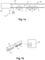
- the longitudinal element to be monitored is a railway rail, for example, the first rail 10 shown in the Figure 1a , forming with a second rail 10' a railway track 20 on which a train 30 can move.
- the rail 10 may be linear or curved, the curvature being able to be in a first and/or a second direction, the first direction being horizontal and perpendicular to the longitudinal axis of the rail 10 and the second direction being vertical and perpendicular to the longitudinal axis of the rail 10.
- the network 14 further comprises a second pair B of sensors formed by a third sensor 3 and a fourth sensor 4 each placed at one end of a second portion 10b of the rail 10, and a third pair C of sensors formed by the fourth sensor 4 and a fifth sensor 5 each placed at one end of a third portion 10c of the rail 10.
- the sensors of the network 14 are integrated into discrete receivers placed regularly and spaced at a constant distance, for example a distance which can range from one meter to a few tens of meters.
- This regular distribution is advantageously chosen over the entire length of the rail which is subject to the same wear conditions.
- the sensors, or the receivers comprising the sensors can be distributed irregularly, over all or part of the rail.
- a different distribution of the sensors, at least over certain lengths of the rail can be interesting to take into account the fact that certain parts of the rail are likely to be subject to greater wear conditions, such as, for example, turning areas.
- a discrete receiver comprises a sensor and a transmitting/recording unit, and is used to measure and record mechanical waves and then transmit the recorded data to the processing system 40.
- Each of the sensors in the sensor network 14 may be chosen from proven technology sensors such as geophones, accelerometers and/or other mechanical wave sensors. In a preferred embodiment, all the sensors in the sensor network 14 may be identical so as to simplify processing and maintenance. According to another possible embodiment, the sensors in the sensor network 14 may be a mixture of different sensors. The sensors may be chosen, for example, based on their robustness, size, ease of deployment and required reliability: thus, for example, a network of identical microsensors (known as Micro-Electro-Mechanical Systems or MEMS) may be preferred.
- MEMS Micro-Electro-Mechanical Systems
- the network 14 of sensors is produced at least partially by an optical fiber 15 secured to the rail and associated with a distributed acoustic detection device (DAS) 17 which is integrated into the processing system 40.
- DAS distributed acoustic detection device
- the DAS technology which is known to those skilled in the art makes it possible to use the optical fiber as a set of equivalent sensors which would be positioned at predefined intervals along the path of the fiber.
- the advantage of DAS technology is that the optical fiber 15 can extend over several tens or even hundreds of kilometers along the rail 10 or any other longitudinal element and is low cost. Furthermore, the position of each of the equivalent sensors along the optical fiber is not fixed in time and can be chosen according to the monitoring that one wishes to carry out. Indeed, the detection of mechanical waves along the rail is done over the entire length of the optical fiber, and it is during the processing step that the position of each of the equivalent sensors is decided according to the portion(s) on which one wishes to carry out monitoring. DAS technology associated with the use of optical fiber thus offers great flexibility of use. As for embodiments using discrete sensors, the DAS device may be configured so that the equivalent sensors are positioned regularly, irregularly, or alternately regularly or irregularly.
- any combination of sensors can be used.
- the two sensors of the same pair of sensors are two identical accelerometers.
- the sensors 1 to 5 are mechanically coupled to the rail 10, preferably by direct contact. Thus, they can directly detect mechanical, seismic or vibratory waves moving along the rail.
- the mechanical waves that can be detected are, for example, generated by a source which is, in this embodiment, the train 30 when it moves on the railway track 20.
- Each of the sensors of the network 14 is connected to a system for processing the detected signals.
- the processing system is represented by a processing system 40 connected (wired or wireless) to each of the sensors of the network 14 which consequently receives the signals detected by each of the sensors of the network.
- the processing system 40 may comprise a physical central unit, or be implemented via the internet (known as “Cloud Computing”).
- the processing system 40 may also comprise processing elements embedded directly on the sensors of the network 14. In fact, the processing system 40 may take any mixed configuration, with embedded processing, “cloud computing” and/or a central unit, making it possible to carry out the signal processing integrated into the invention.
- the processing system 40 is associated with the distributed acoustic detection device 17.
- Each sensor detects the mechanical waves over a predetermined duration and the corresponding signal is transmitted to the processing system 40.
- the detection can be programmed and carried out, for example, for a duration of 60s ranging from 90 seconds to 30 seconds before the trains pass at the pair of sensors.
- the detection can be continuous (with or without sampling) and the signal fraction “interesting” for the rest of the method according to the invention is retained in the processing system 40.
- the processing system 40 comprises means for carrying out an interferometry step of the signals received over a predetermined time period; for example, the interferometry is carried out on a portion of the signal lasting approximately one minute shortly before the train passes, in order to take advantage of a strong and useful signal without saturating the sensors, then only one to a few seconds of correlated signal can be retained for this train passage and this, for each pair of sensors.
- an interferometry method makes it possible to obtain usable signals, freeing oneself from the signature of the source (i.e. the train); in particular, interfered signals (or simplified traces) are obtained by applying interferometry to two signals from a pair of sensors.
- cross-correlation sometimes called correlation
- convolution convolution
- deconvolution deconvolution
- any other interferometry method any other interferometry method.
- the interferometry technique used is cross-correlation (or correlation).
- the first and second sensors each detect a set of mechanical waves moving along the rail 10, said waves being generated by a train or any other power unit moving on the rail at least during the first time period P1.
- Each of the sensors 1 and 2 of the first pair A then delivers a signal corresponding to the set of mechanical waves detected and which is transmitted to the processing system 40.
- the processing system 40 then generates a first intercorrelated signal resulting from a first interferometry step from the signals delivered by the sensors of the first pair A of sensors 1 and 2 over a first predetermined time period P1.
- This interferometry step is preferably carried out by intercorrelation, but any other method would be suitable; the aim here is to overcome the signature of the emitted/detected signal and to extract the propagation component of said signal.
- the signal is decorrelated from the nature of the train as a source so that it will be possible to follow its evolution even if the source changes.
- the intercorrelation of the signals from the first sensor 1 and the second sensor 2 therefore makes it possible to obtain a first signal deconvolved from the signature of the source, this signal representing a simplified, and repeatable, trace of the propagation of mechanical waves within the rail.
- the first interfered signal determined at the end of the processing step makes it possible to extract one or more pieces of information on the physical state of the portion 10a during the first time period P1.
- the first signal can give indications on the physical state of the portion 10a at a given time which corresponds to the first time period.
- a time period according to the invention corresponds to a fraction of the total detection time (or monitoring interval) of the mechanical waves by the sensors of a pair of sensors. This time period can be more or less long depending on the desired signal quality and on the quantity and/or intensity of the mechanical waves detected by the sensors.
- the detection time depends on the nature of the monitoring. The duration of a time period is generally a few seconds which makes it possible to obtain a simplified trace by interferometry. On the other hand, the duration during which the sensors detect the signal can be longer and depend in particular on the duration of the monitoring interval which can be several hours, days or months. It is possible to process only a portion of the waves detected by the sensors.
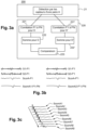
- a first method 100 that can be implemented using the system 12 is illustrated in the Figure 2a This first method allows the monitoring of the physical state of a single portion of the rail 10 over time and will be described for the first portion 10a.
- the method 100 comprises the step 110 of detecting mechanical waves moving along the rail 10, and in particular along the first portion 10a, by the first pair A of sensors 1 and 2.
- the method 100 also comprises the processing step 120 comprising the determination of a first simplified trace, that is to say of a first intercorrelated signal S corA-P1 resulting from a first intercorrelation of a signal S 1-P1 delivered by the first sensor 1 and of a signal S 2-P1 delivered by the second sensor 2, over the first time period ( Figure 2b ).
- the processing system 40 is configured to determine the first intercorrelated signal S corA-P1 and the second intercorrelated signal S corA-P2 and to perform a comparison of the first intercorrelated signal S corA-P1 and the second intercorrelated signal S corA-P2 so as to extract at least one piece of information on the physical state of the first portion 10a.
- the comparison of the first intercorrelated signal S corA-P1 and the second intercorrelated signal S corA-P2 carried out by the processing system 40 makes it possible in particular to evaluate the variation in the physical state of the first portion 10a between the first time period P1 and the second time period P2. This comparison can be done visually, or automatically by any known method, such as a correlation calculation.
- the method 100 makes it possible to conclude that the physical state of the first portion 10a has not varied between the period P1 and the period P2.
- the method 100 makes it possible to know that the physical state of the first portion 10a has varied between the first period P1 and the second period P2. It is then possible to link this signal variation with variations in certain parameters between the periods P1 and P2 such as for example a difference in climatic conditions or a long period of time elapsed which may indicate wear of the rail along this portion.
- the duration and time of day (or week, month, etc.) of the time periods P1 and P2 can be chosen according to the information that one wishes to obtain on the physical state of the first portion 10a of the rail 10. If we want to know, for example, the variation of the physical state of the rail during a day depending on the sunshine, the temperature, the humidity..., each of the periods P1 and P2 can go from several minutes to one or two hours.
- the sensors 1 and 2 of the first pair A can record the mechanical waves moving along the rail continuously, or sampled at a constant frequency, during a predetermined recording phase and the time periods P1 and P2 are selected in this recording phase.
- the phases P1 and P2 each constitute a time fraction of the recording phase.
- the recording phase can have a duration ranging from several seconds to several years.
- the sensors 1 and 2 of the first pair A can record the mechanical waves moving along the rail only during the predetermined periods P1 and P2.
- Periods P1 and P2 can be spaced apart by a duration ranging from a few seconds to a few months or, on the contrary, they can follow one another without interruption.
- the first method 100 is preferably repeated so as to obtain continuous monitoring of the condition of the rail and it can therefore be repeated an unlimited number of times.
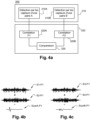
- a second process 200 illustrated on the Figure 3a can also be implemented using the monitoring system 12.
- the second method 200 makes it possible to monitor the rail 10, and in particular to study the variation in its physical state for several durations, each comprising a plurality of time periods.
- This method according to the invention can, for example, make it possible to monitor a portion of rail day after day.
- the processing step also includes the sum 222 of the simplified traces, possibly normalized, in order to obtain a virtual trace S somA1-P1-PN for the monitoring interval.
- the processing step 220 comprises the determination 221' of a second plurality of intercorrelated signals S corA-P'1-P'N corresponding to a correlation of signals delivered by the sensors of the first pair A over a second plurality of time periods, as well as the sum 222' of the signals of the second plurality of intercorrelated signals S corA-P'1-P'N making it possible to obtain a second virtual trace S somA2-P'1-'PN for the second monitoring interval, of duration D' ( Figure 3b ).
- the method is carried out for nine monitoring intervals making it possible to obtain the nine virtual traces S som-A1 to S som-A9 which can be compared with each other to know the evolution of the state of the rail 10.
- the comparison of the virtual traces S som-A1 to S som-A9 makes it possible to identify that the signal varies during the monitoring intervals 1 to 9, and therefore that the physical state of the rail has been modified during these monitoring intervals.
- the method can comprise an alarm step making it possible to alert if the signal, or the difference between the signal and the “normal” average, exceeds a certain threshold.
- each monitoring interval lasts 1 month and the method therefore makes it possible to study the variation in the physical state of the rail 10 over 9 months.
- the modification of the virtual traces S som-A1 to S som-A9 continuously over the 9 months visible on the Figure 3c may for example mean that the rail 10 has worn over time on the portion 10a.
- each monitoring interval may last 1 hour and the method may thus make it possible to study the variation in the physical state of the rail over 9 hours.
- the monitoring intervals run from 5 a.m. to 2 p.m. in a period of high heat
- the variation in the physical state of the rail may mean that the rail has expanded under the effect of the heat.
- the signal shows the same temporal variation or continues a continuous deterioration, it is possible to consider the change as "normal" or to generate an alarm.
- a time period P may for example correspond to the passage of a train on the rail 10 and each monitoring interval may be one day.
- a first virtual trace S SomA1-P1-PN is obtained, the quality of which is improved compared to the intercorrelated signal obtained at each train passage and the method may allow daily monitoring to be carried out in the case where the method is repeated over several days, weeks, months, etc.
- the virtual traces may comprise a different number of occurrences (or even simplified traces), the signals may also have been obtained over time periods of different duration.
- the conditions for recording the signals may be chosen according to parameters inherent to the use of the infrastructure, here to the context of train circulation: the railway operator provides the train passage times (possibly the times of day or year that he considers representative), and the processing is carried out for the periods determined on this basis. Any modification to the passage schedule, whether temporary (traffic hazard) or permanent (change of season) may be taken into account directly by the system according to the invention, by adapting the time periods Pi for the determinations of simplified traces 221, 222.
- the system and method can of course be adapted to repeat the comparisons with more than two virtual traces as shown in the Figure 3c described previously.
- the processing system 40 performs an intercorrelation between at least a fraction of the signals of the pair of sensors and stores the result.
- the processing system performs the sum of the signals recorded, to obtain a first virtual trace that can be normalized, using a spectral whitening step for example.
- the daily virtual traces are then compared in order to evaluate a change in the physical state of the section of rail.
- the third method 300 comprises the detection step 310 which comprises the detection 310 A of the mechanical waves moving along the rail 10, and in particular along the first portion 10a, by the first pair A of sensors 1 and 2.
- the method 300 also comprises the processing step 320 comprising the determination of a first intercorrelated signal S corA-P1 resulting from a first intercorrelation of a signal S 1-P1 delivered by the first sensor 1 and a signal S 2-P1 delivered by the second sensor 2, over the first time period ( Figure 4b ).
- first and second intercorrelated signals S corA-P1 and S corB-P1 are different, it is possible to conclude that one of the two portions is more worn or is more damaged than the other by the conditions, for example climatic or usage, to which the two portions are subjected.
- the comparison can be made in a similar way to that previously described.
- the two signals are identical, it is possible to conclude that the two portions present the same state of wear and/or the same evolution following exposure to particular conditions of temperature, humidity, etc.
- This third method has been described in the case where the first and second portions are spaced apart as is the case for portions 10a and 10b.
- this method 200 can also be applied to a system in which the first and second portions are contiguous and in which one of the sensors in the sensor array is common to the first and second pairs.
- the first portion can be portion 10b and the second portion can be portion 10c.
- the first and second portions have in common the fourth sensor 4 which constitutes the second sensor of pair B and the first sensor of pair C.
- the method 300 is not limited to two rail portions and can instead be applied to a greater or lesser number of portions. According to an exemplary embodiment, the method 300 can be applied to the system 12 illustrated in the Figure 1 and which comprises the first portion 10a, the second portion 10b and a third portion 10c.
- the three portions 10a, 10b and 10c are identical.
- the implementation of the method 300 on these three portions can make it possible to obtain a signal for each of the portions, the three signals can then be compared. For example, obtaining two identical signals and a third signal different from the other two can indicate the presence of at least one anomaly (wear, breakage, deformation, etc.) on one of the three portions.
- the three portions or two of the three portions may present one or more anomalies.
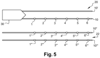
- the sensors were placed only along the rail 10 of the track 20. However, the sensors can be placed on both rails 10 and 10' of the track 20, according to the same distribution or according to a different distribution.
- the waves emitted by the train 30 passing on the track 20 can be used to carry out the monitoring of the subsoil between two rails 10' and 10" of a track 22 which extends parallel to the track 20 according to the method described in the patent application WO2020/021177 .
- pairs of 1"-1′′′ to 5"-5"' sensors can be placed on 10" and 10"' rails of track 22 ( Figure 5 ).
- the pairs of sensors placed on track 22 allow the monitoring of the subsoil between the 10" rail and the 10"' rail by interferometry.
- the monitoring of the subsoil between the two rails 10 and 10' of track 20 could be carried out by placing sensors on the 10' rail and using the waves emitted by a train passing over track 22.
- the sensors 1 to 5 of the rail 10 can also be used to carry out a modal analysis of the rail along which they are placed.
- the modal analysis method is known to those skilled in the art and in particular allows the study of the dynamic model of the rail along which the sensors are placed.
- the optical fiber can be used to measure the deformation of the longitudinal element against which it is placed, for example a railway rail.
- the optical fiber is associated with a DAS device.
- the method 300 can be carried out for a certain number of initial portions, for example with a length of 100 meters.
- a more detailed analysis can be carried out by dividing this initial portion into several secondary portions, for example with a length of 10 meters in order to identify the secondary portion(s) responsible for the anomaly of the initial portion.
- the initial instrumentation of the track can comprise “dormant” sensor systems initially; advantageously, it is the programming of the DAS device which is modified to allow the more detailed segmentation. If more detailed continuous monitoring is envisaged for a portion, it is also possible to add sensors later, within a network of discrete sensors or in combination with an installed optical fiber.
- the first method 100 and the second method 200 can be combined.
- the methods 100, 200 and 300 of the invention thus make it possible to carry out fine measurements of slight variations in the physical state of a rail and therefore to provide a regular diagnosis, for example daily, of the physical state of a rail.
- the method of correlation of the signals by interferometry makes it possible to extract the propagation component of the signal by eliminating the component due to the source. It is then possible to measure identified indicators of the signal such as the propagation speed, the amplitude, the shape of the wave, the resonance frequency, etc., for each portion monitored. The analysis of the variations of these indicators over several time periods for a given portion of the rail and/or for different portions of the rail makes it possible to identify a worn portion of the rail.
- the longitudinal element is a rail and the train or trains passing over the rail are used as a source of mechanical waves.
- the longitudinal element may be any type of longitudinal element associated with a source of mechanical waves such as, for example, cables of a suspension bridge or a structural element of a bridge for which the source of mechanical waves may be the passage of cars over the bridge, or an elevator cable for which the source of mechanical waves may be the movement of the elevator.
- the longitudinal element may not be associated with a source of mechanical waves by its use and a source of mechanical waves may then be added to implement the method according to the invention.
- the source may then be any type of device causing shocks and/or vibrations on the longitudinal element such as for example a device that would tap the longitudinal element at a regular or irregular frequency.
Landscapes
- Physics & Mathematics (AREA)
- General Physics & Mathematics (AREA)
- Engineering & Computer Science (AREA)
- Life Sciences & Earth Sciences (AREA)
- Pathology (AREA)
- Health & Medical Sciences (AREA)
- Chemical & Material Sciences (AREA)
- Analytical Chemistry (AREA)
- Biochemistry (AREA)
- General Health & Medical Sciences (AREA)
- Immunology (AREA)
- Mechanical Engineering (AREA)
- Remote Sensing (AREA)
- Acoustics & Sound (AREA)
- Signal Processing (AREA)
- Environmental & Geological Engineering (AREA)
- Geology (AREA)
- General Life Sciences & Earth Sciences (AREA)
- Geophysics (AREA)
- Train Traffic Observation, Control, And Security (AREA)
- Length Measuring Devices With Unspecified Measuring Means (AREA)
- Length Measuring Devices By Optical Means (AREA)
Claims (15)
- Verfahren (200) zur Überwachung des physikalischen Zustands eines Längselements (10), dadurch gekennzeichnet, dass es Folgendes aufweist:- einen Schritt (210) zum Erfassen mechanischer Wellen, die sich entlang des Längselements (10) bewegen, mithilfe eines Netzes (14) von Sensoren für mechanische Wellen, die entlang des Längselements und in Kontakt mit diesem angeordnet sind, wobei das Netz (14) mindestens ein erstes Paar (A) von Sensoren (1, 2) aufweist, die jeweils an einem Ende eines ersten Abschnitts (10a) des Längselements (10) positioniert sind, und- einen Schritt (220) zum Verarbeiten, der Folgendes aufweist:• Bestimmen (221) einer Vielzahl von vereinfachten Spuren (ScorAP1-Pi), wobei sich jede vereinfachte Spur (SCorapi) aus der Interferometrie von Signalen (S1-P1, S2-P1) ergibt, die von den Sensoren des ersten Paars A über einen vorbestimmten Zeitraum (Pi) geliefert werden, wobei das Verfahren dadurch gekennzeichnet ist, dass der Schritt zum Verarbeiten Folgendes aufweist:• Bestimmen (222) von mindestens einer ersten und einer zweiten virtuellen Spur (SsomA1, SsomA2), wobei die erste virtuelle Spur (SsomA1) der Summe von vereinfachten Spuren entspricht, die während eines ersten Überwachungsintervalls bestimmt wurden, und die zweite virtuelle Spur (SsomA2) der Summe von vereinfachten Spuren entspricht, die während eines zweiten Überwachungsintervalls bestimmt wurden, wobei das erste und das zweite Überwachungsintervall unterschiedlich sind und jeweils eine Vielzahl von vorbestimmten Zeiträumen aufweisen, und• Vergleichen (223) mindestens der ersten virtuellen Spur (SsomA1) mit der zweiten virtuellen Spur (SsomA2), um so mindestens eine Information über den physikalischen Zustand des ersten Abschnitts (10a) zu extrahieren.
- Verfahren nach Anspruch 1, dadurch gekennzeichnet, dass die Interferometrie eine Interkorrelation ist.
- Verfahren nach Anspruch 1 oder 2, dadurch gekennzeichnet, dass das Netz (14) von Sensoren eine Glasfaser (15) aufweist, die einer verteilten akustischen Erfassungsvorrichtung (DAS) (17) zugeordnet ist, wobei das erste Paar von Sensoren (1, 2) während des Schritts zum Verarbeiten (220) durch das DAS-System auf der Glasfaser definiert wird.
- Verfahren nach einem der vorhergehenden Ansprüche, dadurch gekennzeichnet, dass das Bestimmen der virtuellen Spuren einen Normalisierungsschritt aufweist.
- Verfahren nach Anspruch 4, dadurch gekennzeichnet, dass der Normalisierungsschritt durch spektrale Bleichung durchgeführt wird.
- Verfahren nach einem der vorhergehenden Ansprüche, dadurch gekennzeichnet, dass die Erfassung der mechanischen Wellen kontinuierlich durchgeführt wird.
- Verfahren nach einem der vorhergehenden Ansprüche, dadurch gekennzeichnet, dass es für eine Vielzahl von Sensorpaaren durchgeführt wird.
- Verfahren nach einem der vorangehenden Ansprüche, dadurch gekennzeichnet, dass die Überwachungsintervalle von identischer Dauer sind, insbesondere gleich einem Tag.
- Verfahren nach einem der vorangehenden Ansprüche, dadurch gekennzeichnet, dass das Längselement (10) eine Schiene eines Eisenbahngleises ist, wobei die erfassten mechanischen Wellen einem Vorbeifahren eines Zuges auf der Schiene entsprechen.
- Verfahren nach Anspruch 9, dadurch gekennzeichnet, dass jeder Zeitraum einem Vorbeifahren eines Zuges auf der Schiene entspricht, wobei die Erfassung erfolgt, bevor der Zug auf dem ersten Abschnitt ankommt.
- System (12) zur Überwachung des physikalischen Zustands eines Längselements (10), dadurch gekennzeichnet, dass es Folgendes aufweist:- ein Netz (12) von Sensoren für mechanische Wellen, die entlang des Längselements und in Kontakt mit diesem angeordnet sind, wobei das Netz (12) mindestens ein erstes Paar (A) von Sensoren aufweist, die jeweils an einem Ende eines ersten Abschnitts (10a) des Längselements (10) positioniert sind, und- ein System (40) zur Verarbeitung von Signalen, die von den Sensoren des Netzes (12) von Sensoren stammen, wobei das Verarbeitungssystem (40) konfiguriert ist, um• eine Vielzahl von vereinfachten Spuren (ScorAP1-Pi) durch Interferometrie von Signalen (S1-P1, S2-P1) zu bestimmen, die von den Sensoren (1, 2) des ersten Paars (A) von Sensoren über einen vorbestimmten Zeitraum (Pi) ausgegeben werden, dadurch gekennzeichnet, dass das Verarbeitungssystem konfiguriert ist, um• mindestens eine erste und eine zweite virtuelle Spur (SsomA1, SsomA2) zu berechnen, wobei die erste virtuelle Spur (SsomA1) der Summe von vereinfachten Spuren entspricht, die während eines ersten Überwachungsintervalls bestimmt wurden, und die zweite virtuelle Spur (SsomA2) der Summe von vereinfachten Spuren entspricht, die während eines zweiten Überwachungsintervalls bestimmt wurden, wobei das erste und das zweite Überwachungsintervall unterschiedlich sind und jeweils eine Vielzahl von vorbestimmten Zeiträumen aufweisen, und• mindestens die erste virtuelle Spur mit der zweiten virtuellen Spur zu vergleichen, um so mindestens eine Information über den physikalischen Zustand des ersten Abschnitts (10a) zu extrahieren.
- System nach Anspruch 11, dadurch gekennzeichnet, dass mindestens ein Sensor des Netzes (12) von Sensoren ein Geophon oder ein Beschleunigungsmesser ist.
- System nach einem der Ansprüche 11 oder 12, dadurch gekennzeichnet, dass das Netz (12) von Sensoren zumindest teilweise durch eine Glasfaser realisiert wird, die einer verteilten akustischen Erfassungsvorrichtung (DAS) zugeordnet ist.
- System nach einem der Ansprüche 11 bis 13, dadurch gekennzeichnet, dass das System eine Quelle für mechanische Wellen aufweist, die so konfiguriert ist, dass sie die mechanischen Wellen erzeugt, die von dem Netz (12) von Sensoren erfasst werden.
- System nach einem der Ansprüche 11 bis 14, dadurch gekennzeichnet, dass das Längselement (10) eine Schiene eines Eisenbahngleises ist und dass das Netz (12) von Sensoren geeignet ist, die mechanischen Wellen zu erfassen, die durch das Vorbeifahren mindestens eines Zuges auf dem Gleis erzeugt werden.
Applications Claiming Priority (3)
| Application Number | Priority Date | Filing Date | Title |
|---|---|---|---|
| FR2007822A FR3112853B3 (fr) | 2020-07-24 | 2020-07-24 | Surveillance de l’état physique d’un élément longitudinal |
| FR2010104A FR3114886B1 (fr) | 2020-10-02 | 2020-10-02 | Surveillance de l’état physique d’un élément longitudinal |
| PCT/FR2021/051381 WO2022018388A1 (fr) | 2020-07-24 | 2021-07-23 | Surveillance de l'etat physique d'un rail |
Publications (3)
| Publication Number | Publication Date |
|---|---|
| EP4185845A1 EP4185845A1 (de) | 2023-05-31 |
| EP4185845B1 true EP4185845B1 (de) | 2025-06-25 |
| EP4185845C0 EP4185845C0 (de) | 2025-06-25 |
Family
ID=77367445
Family Applications (1)
| Application Number | Title | Priority Date | Filing Date |
|---|---|---|---|
| EP21755803.0A Active EP4185845B1 (de) | 2020-07-24 | 2021-07-23 | Verfahren zur überwachung des physikalischen zustands einer schiene |
Country Status (4)
| Country | Link |
|---|---|
| US (1) | US12214814B2 (de) |
| EP (1) | EP4185845B1 (de) |
| AU (1) | AU2021312362A1 (de) |
| WO (1) | WO2022018388A1 (de) |
Families Citing this family (3)
| Publication number | Priority date | Publication date | Assignee | Title |
|---|---|---|---|---|
| EP4360989A1 (de) * | 2022-10-26 | 2024-05-01 | Frauscher Sensor Technology Group GmbH | Verfahren und vorrichtung zur erkennung von anomalien entlang eines gleises |
| CN115805973A (zh) * | 2022-11-30 | 2023-03-17 | 中国铁路昆明局集团有限公司 | 一种道岔尖心轨折断监测系统及方法 |
| CN120024375B (zh) * | 2025-04-16 | 2025-07-08 | 浙江华东测绘与工程安全技术有限公司 | 一种轨道交通结构健康监测方法 |
Family Cites Families (8)
| Publication number | Priority date | Publication date | Assignee | Title |
|---|---|---|---|---|
| US6424150B2 (en) * | 1999-03-17 | 2002-07-23 | Southwest Research Institute | Magnetostrictive sensor rail inspection system |
| NO341972B1 (en) | 2016-09-07 | 2018-03-05 | Stiftelsen Norsar | A railway track condition monitoring system for detecting a partial or complete disruption of a rail of the railway track |
| WO2018106677A1 (en) | 2016-12-05 | 2018-06-14 | The Regent Of The University Of California | Ultrasonic inspection of railroad tracks |
| FR3060743B1 (fr) * | 2016-12-15 | 2019-05-17 | Commissariat A L'energie Atomique Et Aux Energies Alternatives | Procede et systeme de controle de sante integre d'une structure mecanique par ondes elastiques diffuses |
| US11565733B2 (en) * | 2017-02-23 | 2023-01-31 | Auto Drive Solutions, S.L. | Speed control and track change detection device suitable for railways |
| FR3084473B1 (fr) | 2018-07-24 | 2021-06-18 | Cgg Services Sas | Procede et dispositif de surveillance du sous-sol terrestre sous une zone cible |
| FR3084748B1 (fr) * | 2018-08-01 | 2024-01-05 | Commissariat Energie Atomique | Controle de sante de rails |
| US11001282B2 (en) * | 2018-10-24 | 2021-05-11 | Mitsubishi Electric Corporation | Rail state monitoring apparatus |
-
2021
- 2021-07-23 WO PCT/FR2021/051381 patent/WO2022018388A1/fr not_active Ceased
- 2021-07-23 US US18/005,870 patent/US12214814B2/en active Active
- 2021-07-23 AU AU2021312362A patent/AU2021312362A1/en active Pending
- 2021-07-23 EP EP21755803.0A patent/EP4185845B1/de active Active
Also Published As
| Publication number | Publication date |
|---|---|
| US20230278606A1 (en) | 2023-09-07 |
| US12214814B2 (en) | 2025-02-04 |
| EP4185845A1 (de) | 2023-05-31 |
| AU2021312362A1 (en) | 2023-02-16 |
| EP4185845C0 (de) | 2025-06-25 |
| WO2022018388A1 (fr) | 2022-01-27 |
Similar Documents
| Publication | Publication Date | Title |
|---|---|---|
| EP4185845B1 (de) | Verfahren zur überwachung des physikalischen zustands einer schiene | |
| EP3555585B1 (de) | Verfahren und system zur steuerung der integrierten gesundheit einer mechanischen struktur durch diffuse elastische wellen | |
| CA3108106A1 (fr) | Controle de sante de rails | |
| FR3073289A1 (fr) | Controle de sante d'une structure industrielle | |
| FR3034190B1 (fr) | Capteur a fibre optique distribue d'etat de contrainte | |
| FR2693557A1 (fr) | Procédé et dispositif pour l'évaluation des précipitations sur une zone de terrain. | |
| EP2307856A1 (de) | Selbstreferenzierter glasfasersensor mit stimulierter brillouin-streuung | |
| EP3966534B1 (de) | Verfahren zum wiegen eines eine brücke überfahrenden fahrzeugs | |
| EP3243042B1 (de) | Faseroptischer sensor | |
| Hafizi et al. | Impact location determination on thin laminated composite plates using an NIR-FBG sensor system | |
| EP1954544B1 (de) | Verfahren und vorrichtung zur entdeckung von fehlern in der rundheit von eisenbahnrädern und system mit einer solchen vorrichtung | |
| WO2015097383A1 (fr) | Dispositif de caractérisation d'un phénomène physique par ablation de fibre optique à réseaux de bragg | |
| EP2828635B1 (de) | System zur messung einer trennzone bei einem substrat | |
| FR3114886A1 (fr) | Surveillance de l’état physique d’un élément longitudinal | |
| FR3112853A3 (fr) | Surveillance de l’état physique d’un élément longitudinal | |
| EP3803637B1 (de) | Verfahren zur bestimmung einer verschiebung von mindestens einem referenzpunkt eines objekts und system zur umsetzung des verfahrens | |
| EP1887316B1 (de) | Device for the measurement of deformations of a profile subject to one or more forces | |
| FR3065526B1 (fr) | Systeme de detection d'un etat ou d'un dysfonctionnement par analyse vibratoire | |
| EP0511119B1 (de) | Fiberoptischer Schwingungsfühler und Beschleunigungsmesser mit Benutzung von solchem Fühler | |
| FR3100550A1 (fr) | Procédé d'entretien d'une route équipée d'un système de mesure | |
| WO2003008903A1 (fr) | Procede et dispositif de veille sismique |
Legal Events
| Date | Code | Title | Description |
|---|---|---|---|
| STAA | Information on the status of an ep patent application or granted ep patent |
Free format text: STATUS: UNKNOWN |
|
| STAA | Information on the status of an ep patent application or granted ep patent |
Free format text: STATUS: THE INTERNATIONAL PUBLICATION HAS BEEN MADE |
|
| PUAI | Public reference made under article 153(3) epc to a published international application that has entered the european phase |
Free format text: ORIGINAL CODE: 0009012 |
|
| STAA | Information on the status of an ep patent application or granted ep patent |
Free format text: STATUS: REQUEST FOR EXAMINATION WAS MADE |
|
| 17P | Request for examination filed |
Effective date: 20230127 |
|
| AK | Designated contracting states |
Kind code of ref document: A1 Designated state(s): AL AT BE BG CH CY CZ DE DK EE ES FI FR GB GR HR HU IE IS IT LI LT LU LV MC MK MT NL NO PL PT RO RS SE SI SK SM TR |
|
| DAV | Request for validation of the european patent (deleted) | ||
| DAX | Request for extension of the european patent (deleted) | ||
| GRAP | Despatch of communication of intention to grant a patent |
Free format text: ORIGINAL CODE: EPIDOSNIGR1 |
|
| STAA | Information on the status of an ep patent application or granted ep patent |
Free format text: STATUS: GRANT OF PATENT IS INTENDED |
|
| INTG | Intention to grant announced |
Effective date: 20250122 |
|
| GRAS | Grant fee paid |
Free format text: ORIGINAL CODE: EPIDOSNIGR3 |
|
| GRAA | (expected) grant |
Free format text: ORIGINAL CODE: 0009210 |
|
| STAA | Information on the status of an ep patent application or granted ep patent |
Free format text: STATUS: THE PATENT HAS BEEN GRANTED |
|
| AK | Designated contracting states |
Kind code of ref document: B1 Designated state(s): AL AT BE BG CH CY CZ DE DK EE ES FI FR GB GR HR HU IE IS IT LI LT LU LV MC MK MT NL NO PL PT RO RS SE SI SK SM TR |
|
| REG | Reference to a national code |
Ref country code: GB Ref legal event code: FG4D Free format text: NOT ENGLISH |
|
| REG | Reference to a national code |
Ref country code: CH Ref legal event code: EP |
|
| REG | Reference to a national code |
Ref country code: CH Ref legal event code: EP |
|
| REG | Reference to a national code |
Ref country code: IE Ref legal event code: FG4D Free format text: LANGUAGE OF EP DOCUMENT: FRENCH |
|
| REG | Reference to a national code |
Ref country code: DE Ref legal event code: R096 Ref document number: 602021032905 Country of ref document: DE |
|
| U01 | Request for unitary effect filed |
Effective date: 20250710 |
|
| U07 | Unitary effect registered |
Designated state(s): AT BE BG DE DK EE FI FR IT LT LU LV MT NL PT RO SE SI Effective date: 20250717 |
|
| U20 | Renewal fee for the european patent with unitary effect paid |
Year of fee payment: 5 Effective date: 20250827 |
|
| PG25 | Lapsed in a contracting state [announced via postgrant information from national office to epo] |
Ref country code: GR Free format text: LAPSE BECAUSE OF FAILURE TO SUBMIT A TRANSLATION OF THE DESCRIPTION OR TO PAY THE FEE WITHIN THE PRESCRIBED TIME-LIMIT Effective date: 20250926 Ref country code: NO Free format text: LAPSE BECAUSE OF FAILURE TO SUBMIT A TRANSLATION OF THE DESCRIPTION OR TO PAY THE FEE WITHIN THE PRESCRIBED TIME-LIMIT Effective date: 20250925 |
|
| PGFP | Annual fee paid to national office [announced via postgrant information from national office to epo] |
Ref country code: GB Payment date: 20250724 Year of fee payment: 5 |
|
| PG25 | Lapsed in a contracting state [announced via postgrant information from national office to epo] |
Ref country code: HR Free format text: LAPSE BECAUSE OF FAILURE TO SUBMIT A TRANSLATION OF THE DESCRIPTION OR TO PAY THE FEE WITHIN THE PRESCRIBED TIME-LIMIT Effective date: 20250625 |
|
| PGFP | Annual fee paid to national office [announced via postgrant information from national office to epo] |
Ref country code: CH Payment date: 20250801 Year of fee payment: 5 |
|
| PG25 | Lapsed in a contracting state [announced via postgrant information from national office to epo] |
Ref country code: RS Free format text: LAPSE BECAUSE OF FAILURE TO SUBMIT A TRANSLATION OF THE DESCRIPTION OR TO PAY THE FEE WITHIN THE PRESCRIBED TIME-LIMIT Effective date: 20250925 |