EP4185411B1 - Verfahren zum zusammenbau eines nadelventils - Google Patents
Verfahren zum zusammenbau eines nadelventils Download PDFInfo
- Publication number
- EP4185411B1 EP4185411B1 EP21754946.8A EP21754946A EP4185411B1 EP 4185411 B1 EP4185411 B1 EP 4185411B1 EP 21754946 A EP21754946 A EP 21754946A EP 4185411 B1 EP4185411 B1 EP 4185411B1
- Authority
- EP
- European Patent Office
- Prior art keywords
- valve
- valve seat
- needle
- housing
- seat plate
- Prior art date
- Legal status (The legal status is an assumption and is not a legal conclusion. Google has not performed a legal analysis and makes no representation as to the accuracy of the status listed.)
- Active
Links
Images
Classifications
-
- B—PERFORMING OPERATIONS; TRANSPORTING
- B05—SPRAYING OR ATOMISING IN GENERAL; APPLYING FLUENT MATERIALS TO SURFACES, IN GENERAL
- B05B—SPRAYING APPARATUS; ATOMISING APPARATUS; NOZZLES
- B05B1/00—Nozzles, spray heads or other outlets, with or without auxiliary devices such as valves, heating means
- B05B1/30—Nozzles, spray heads or other outlets, with or without auxiliary devices such as valves, heating means designed to control volume of flow, e.g. with adjustable passages
- B05B1/3033—Nozzles, spray heads or other outlets, with or without auxiliary devices such as valves, heating means designed to control volume of flow, e.g. with adjustable passages the control being effected by relative coaxial longitudinal movement of the controlling element and the spray head
- B05B1/304—Nozzles, spray heads or other outlets, with or without auxiliary devices such as valves, heating means designed to control volume of flow, e.g. with adjustable passages the control being effected by relative coaxial longitudinal movement of the controlling element and the spray head the controlling element being a lift valve
- B05B1/3046—Nozzles, spray heads or other outlets, with or without auxiliary devices such as valves, heating means designed to control volume of flow, e.g. with adjustable passages the control being effected by relative coaxial longitudinal movement of the controlling element and the spray head the controlling element being a lift valve the valve element, e.g. a needle, co-operating with a valve seat located downstream of the valve element and its actuating means, generally in the proximity of the outlet orifice
-
- B—PERFORMING OPERATIONS; TRANSPORTING
- B05—SPRAYING OR ATOMISING IN GENERAL; APPLYING FLUENT MATERIALS TO SURFACES, IN GENERAL
- B05C—APPARATUS FOR APPLYING FLUENT MATERIALS TO SURFACES, IN GENERAL
- B05C11/00—Component parts, details or accessories not specifically provided for in groups B05C1/00 - B05C9/00
- B05C11/10—Storage, supply or control of liquid or other fluent material; Recovery of excess liquid or other fluent material
- B05C11/1002—Means for controlling supply, i.e. flow or pressure, of liquid or other fluent material to the applying apparatus, e.g. valves
- B05C11/1034—Means for controlling supply, i.e. flow or pressure, of liquid or other fluent material to the applying apparatus, e.g. valves specially designed for conducting intermittent application of small quantities, e.g. drops, of coating material
-
- B—PERFORMING OPERATIONS; TRANSPORTING
- B05—SPRAYING OR ATOMISING IN GENERAL; APPLYING FLUENT MATERIALS TO SURFACES, IN GENERAL
- B05C—APPARATUS FOR APPLYING FLUENT MATERIALS TO SURFACES, IN GENERAL
- B05C5/00—Apparatus in which liquid or other fluent material is projected, poured or allowed to flow on to the surface of the work
- B05C5/02—Apparatus in which liquid or other fluent material is projected, poured or allowed to flow on to the surface of the work the liquid or other fluent material being discharged through an outlet orifice by pressure, e.g. from an outlet device in contact or almost in contact, with the work
- B05C5/0225—Apparatus in which liquid or other fluent material is projected, poured or allowed to flow on to the surface of the work the liquid or other fluent material being discharged through an outlet orifice by pressure, e.g. from an outlet device in contact or almost in contact, with the work characterised by flow controlling means, e.g. valves, located proximate the outlet
-
- F—MECHANICAL ENGINEERING; LIGHTING; HEATING; WEAPONS; BLASTING
- F16—ENGINEERING ELEMENTS AND UNITS; GENERAL MEASURES FOR PRODUCING AND MAINTAINING EFFECTIVE FUNCTIONING OF MACHINES OR INSTALLATIONS; THERMAL INSULATION IN GENERAL
- F16K—VALVES; TAPS; COCKS; ACTUATING-FLOATS; DEVICES FOR VENTING OR AERATING
- F16K1/00—Lift valves or globe valves, i.e. cut-off apparatus with closure members having at least a component of their opening and closing motion perpendicular to the closing faces
- F16K1/32—Details
- F16K1/34—Cutting-off parts, e.g. valve members, seats
- F16K1/36—Valve members
-
- F—MECHANICAL ENGINEERING; LIGHTING; HEATING; WEAPONS; BLASTING
- F16—ENGINEERING ELEMENTS AND UNITS; GENERAL MEASURES FOR PRODUCING AND MAINTAINING EFFECTIVE FUNCTIONING OF MACHINES OR INSTALLATIONS; THERMAL INSULATION IN GENERAL
- F16K—VALVES; TAPS; COCKS; ACTUATING-FLOATS; DEVICES FOR VENTING OR AERATING
- F16K1/00—Lift valves or globe valves, i.e. cut-off apparatus with closure members having at least a component of their opening and closing motion perpendicular to the closing faces
- F16K1/32—Details
- F16K1/34—Cutting-off parts, e.g. valve members, seats
- F16K1/42—Valve seats
- F16K1/427—Attachment of the seat to the housing by one or more additional fixing elements
-
- B—PERFORMING OPERATIONS; TRANSPORTING
- B05—SPRAYING OR ATOMISING IN GENERAL; APPLYING FLUENT MATERIALS TO SURFACES, IN GENERAL
- B05C—APPARATUS FOR APPLYING FLUENT MATERIALS TO SURFACES, IN GENERAL
- B05C5/00—Apparatus in which liquid or other fluent material is projected, poured or allowed to flow on to the surface of the work
- B05C5/02—Apparatus in which liquid or other fluent material is projected, poured or allowed to flow on to the surface of the work the liquid or other fluent material being discharged through an outlet orifice by pressure, e.g. from an outlet device in contact or almost in contact, with the work
- B05C5/027—Coating heads with several outlets, e.g. aligned transversally to the moving direction of a web to be coated
-
- B—PERFORMING OPERATIONS; TRANSPORTING
- B23—MACHINE TOOLS; METAL-WORKING NOT OTHERWISE PROVIDED FOR
- B23P—METAL-WORKING NOT OTHERWISE PROVIDED FOR; COMBINED OPERATIONS; UNIVERSAL MACHINE TOOLS
- B23P15/00—Making specific metal objects by operations not covered by a single other subclass or a group in this subclass
- B23P15/001—Making specific metal objects by operations not covered by a single other subclass or a group in this subclass valves or valve housings
-
- F—MECHANICAL ENGINEERING; LIGHTING; HEATING; WEAPONS; BLASTING
- F16—ENGINEERING ELEMENTS AND UNITS; GENERAL MEASURES FOR PRODUCING AND MAINTAINING EFFECTIVE FUNCTIONING OF MACHINES OR INSTALLATIONS; THERMAL INSULATION IN GENERAL
- F16K—VALVES; TAPS; COCKS; ACTUATING-FLOATS; DEVICES FOR VENTING OR AERATING
- F16K2200/00—Details of valves
- F16K2200/10—Means for compensation of misalignment between seat and closure member
- F16K2200/102—Means for compensation of misalignment between seat and closure member seat self-aligning to closure member
-
- F—MECHANICAL ENGINEERING; LIGHTING; HEATING; WEAPONS; BLASTING
- F16—ENGINEERING ELEMENTS AND UNITS; GENERAL MEASURES FOR PRODUCING AND MAINTAINING EFFECTIVE FUNCTIONING OF MACHINES OR INSTALLATIONS; THERMAL INSULATION IN GENERAL
- F16K—VALVES; TAPS; COCKS; ACTUATING-FLOATS; DEVICES FOR VENTING OR AERATING
- F16K27/00—Construction of housing; Use of materials therefor
- F16K27/02—Construction of housing; Use of materials therefor of lift valves
Definitions
- the invention relates to a method for assembling a needle valve according to the preamble of claim 1.
- Needle valves with one or more valve needles and a corresponding number of valve seats are used, for example, to apply fluids such as adhesives, sealants, insulating materials or other viscous materials to workpieces with high precision in the form of beads or dots of material.
- fluids such as adhesives, sealants, insulating materials or other viscous materials
- Increasingly thinner valve needles are being used, which close correspondingly small outlet openings on the respective associated valve seat.
- the use of such valve needles with small diameters and correspondingly small valve seats places high demands on the precision when assembling the needle valves. In particular, it is difficult to position and fix the valve seat in question in relation to the associated valve needle in such a way that the valve needle can sit on it precisely in such a way that good sealing performance is guaranteed.
- a valve seat can self-center with respect to the valve needle assigned to it if the valve needle, while a valve seat plate carrying the valve seat is being fixed to the housing in which the valve needle is guided so as to be longitudinally displaceable, performs an oscillating movement that corresponds to the movement it performs during operation when it is repeatedly lifted off the valve seat and placed on it at regular intervals.
- the valve seat plate is attached to the housing using fastening means.
- the valve seat plate is not fixed to the housing in the first step, but only fastened to the extent that it can still move to a limited extent with respect to the housing.
- each valve needle is set in the oscillating movement, and in a third step the valve seat plate is fixed to the housing while the valve needle(s) move back and forth.
- the at least one valve needle is moved back and forth at a frequency of 10 Hz to 100 Hz, preferably from 30 Hz to 70 Hz and more preferably from 45 Hz to 55 Hz, since frequencies around 50 Hz have proven to be the most effective.
- the valve seat plate is expediently fixed in the first spatial direction with respect to the housing, while it is movable to a limited extent in the other two spatial directions. It can then move to the side in order to be able to center each valve seat with respect to the associated valve needle.
- the fastening means are expediently screws passed through the valve seat plate, which in the first step are screwed up to the In the third step, they are screwed into the housing until a first torque is reached and then until a larger second torque is reached.
- Hard metal is preferred as the material for each valve needle and each valve seat. Hard metal is chemically resistant to the materials that the needle valve is regularly used to apply. Hard metal is a metal matrix composite material in which hard materials in particle form are held together by a matrix of metal. Hard materials used are in particular metal carbides or metal nitrides, such as tungsten carbide, titanium carbide, titanium nitride, niobium carbide, tantalum carbide or vanadium carbide. It is then also preferred that the valve seat plate has a base plate made of metal, preferably stainless steel, which supports the at least one valve seat. In particular, all valve seats can be combined in one piece to form a hard metal component that is accommodated in the base plate, which in turn is attached to the housing. Stainless steel in particular has a high level of elasticity, which is advantageous when fixing it to the housing in the third step, whereas hard metal is more brittle. If screws are used to fix it to the housing, these are advantageously passed through the base plate.
- the needle valve can be equipped with only one valve needle and one valve seat. However, it is preferred that it has several valve needles extending parallel to one another in the first spatial direction, which are preferably arranged in a row in the sense that a straight line extending perpendicular to the first spatial direction can be laid through all the valve needles.
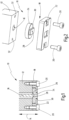
- a needle valve 10 is shown schematically in section, which has a housing 12 and a valve needle 16 made of hard metal that is guided longitudinally displaceably in the housing 12 in a first spatial direction 14.
- a valve seat plate 18 is fixed to the housing 12 by means of fastening means 20, which are screws 20 in the embodiment shown here.
- the valve seat plate 18 has a base plate 22 made of stainless steel and a valve seat block 24 with a valve seat 26 assigned to the valve needle 16, on which an outlet opening 28 for a fluid that can be applied by means of the needle valve 10 can be closed and opened by moving the valve needle 16 back and forth and thereby lifting it off and placing it on the valve seat 26.
- the valve seat block 24 is accommodated in the base plate 22 and has a shoulder 30 so that it can only be inserted into the base plate 22 from the side facing the housing 12. It is made in one piece from the same hard metal as the valve needle 16.
- valve seat block 24 When assembling the needle valve 10 from the Fig. 2 shown individual parts, the valve seat block 24 is first inserted into the base plate 22 and together with it forms the valve seat plate 18. This is placed against the housing 12 from below, and the screws 20 are pushed through the base plate 22 and screwed into threaded screw holes 32 in the housing until they are subjected to a first predetermined torque. The valve seat plate 18 then rests almost immobile on the housing 12 in the first spatial direction 14, but still has some play in the other two spatial directions that are perpendicular to the first spatial direction 14 and to one another. The valve needle 16 is then set in an oscillating movement that is equivalent to a successive opening and closing of the needle valve 10 at a frequency of approximately 50 Hz.
- the screws 20 are tightened until they are subjected to a predetermined second torque that is greater than the first torque.
- the constant lifting of the valve needle 16 from the valve seat 26 and the subsequent placement causes a self-centering of the valve seat 26 with respect to the valve needle 16, so that the valve seat 26 can be positioned very precisely with respect to the valve needle 16.
- the needle valve 10 has only one valve needle 16 and the associated valve seat 26. It goes without saying that the method according to the invention can also be applied to needle valves that have several valve needles and a valve seat for each valve needle.
- the valve seat block has, for example, several valve seats arranged in a row, while the design of the needle valve is essentially the same as shown in the drawing.
- the invention relates to a method for assembling a needle valve 10, which has a housing 12, at least one valve needle 16 guided longitudinally displaceably in the housing 12 in a first spatial direction 14 and a valve seat plate 18, wherein the valve seat plate 18 has a valve seat 26 assigned to each valve needle 16, on which an outlet opening 28 for a fluid can be closed and opened by a back and forth movement of the respective valve needle 16.
- valve seat plate 18 is fastened to the housing 12 in a first step by means of fastening means 20 so that it is movable to a limited extent with respect to the housing 12, that in a second step each valve needle 16 is set in a back and forth movement in which it is alternately placed on and lifted off the valve seat 26 assigned to it, and that the valve seat plate 18 is fixed to the housing 12 in a third step while the at least one valve needle 16 moves back and forth.
Landscapes
- Engineering & Computer Science (AREA)
- General Engineering & Computer Science (AREA)
- Mechanical Engineering (AREA)
- Lift Valve (AREA)
Description
- Die Erfindung betrifft ein Verfahren zum Zusammenbau eines Nadelventils gemäß Oberbegriff des Anspruchs 1.
- Nadelventile mit einer oder mehreren Ventilnadeln und einer entsprechenden Anzahl an Ventilsitzen werden beispielsweise dazu verwendet, Fluide, wie beispielsweise Klebstoffe, Dichtstoffe, Dämmstoffe oder andere viskose Materialien mit hoher Präzision in Form von Materialraupen oder Materialpunkten auf Werkstücke aufzutragen. Dabei werden zunehmend dünnere Ventilnadeln verwendet, die entsprechend kleine Auslassöffnungen am jeweils zugeordneten Ventilsitz verschließen. Die Verwendung solcher Ventilnadeln mit geringen Durchmessern und entsprechend kleiner Ventilsitze stellt hohe Anforderungen an die Präzision beim Zusammenbau der Nadelventile. Insbesondere ist es schwierig, den betreffenden Ventilsitz bezüglich der zugeordneten Ventilnadel so zu positionieren und zu fixieren, dass die Ventilnadel exakt so auf ihm aufsitzen kann, dass eine gute Dichtleistung gewährleistet ist.
- Ein Verfahren der eingangs genannten Art ist der Anmelderin aus ihrer betrieblichen Praxis bekannt. Aus der
DE 19 621 835 A1 , derDE 691 26 667 T2 , derUS 2009/0107398 A1 , derUS 5 618 566 A und derUS 2019/0337008 A1 sind verschiedene Nadelventile bekannt. - Es ist daher Aufgabe der Erfindung, ein Verfahren für den Zusammenbau eines Nadelventils bereitzustellen, das eine bessere Positionierung des Ventilsitzes oder der Ventilsitze bezüglich der Ventilnadel(n) ermöglicht.
- Diese Aufgabe wird erfindungsgemäß durch ein Verfahren mit den Merkmalen des Anspruchs 1 gelöst. Vorteilhafte Weiterbildungen der Erfindung sind Gegenstand der abhängigen Ansprüche.
- Der Erfindung liegt die experimentell von der Anmelderin gefundene Erkenntnis zugrunde, dass eine Selbstzentrierung eines Ventilsitzes bezüglich der ihm zugeordneten Ventilnadel erfolgen kann, wenn die Ventilnadel während des Fixierens einer den Ventilsitz tragenden Ventilsitzplatte am Gehäuse, in dem die Ventilnadel längsverschieblich geführt ist, eine oszillierende Bewegung durchführt, die der Bewegung entspricht, die sie im Betrieb ausführt, wenn sie in regelmäßigen Abständen immer wieder vom Ventilsitz abgehoben und auf diesen aufgesetzt wird. In einem ersten Schritt wird die Ventilsitzplatte mittels Befestigungsmitteln am Gehäuse befestigt. Entgegen der üblichen Vorgehensweise wird die Ventilsitzplatte im ersten Schritt aber nicht am Gehäuse fixiert, sondern nur soweit befestigt, dass sie bezüglich des Gehäuses noch begrenzt beweglich ist. Dann wird in einem zweiten Schritt jede Ventilnadel in die oszillierende Bewegung versetzt, und in einem dritten Schritt wird die Ventilsitzplatte am Gehäuse fixiert, während sich die Ventilnadel(n) hin und her bewegt bzw. bewegen.
- Es wird bevorzugt, dass die mindestens eine Ventilnadel mit einer Frequenz von 10 Hz bis 100 Hz, vorzugsweise von 30 Hz bis 70 Hz und weiter vorzugsweise von 45 Hz bis 55 Hz hin und her bewegt wird, da sich Frequenzen um die 50 Hz als am effektivsten erwiesen haben. Zweckmäßig ist die Ventilsitzplatte nach dem ersten Schritt bezüglich des Gehäuses in der ersten Raumrichtung fixiert, während sie in den beiden weiteren Raumrichtungen begrenzt beweglich ist. Sie kann dann zur Seite hin ausweichen, um jeden Ventilsitz bezüglich der zugehörigen Ventilnadel zentrieren zu können. Zweckmäßig sind die Befestigungsmittel durch die Ventilsitzplatte durchgeführte Schrauben, welche im ersten Schritt bis zum Erreichen eines ersten Drehmoments und im dritten Schritt bis zum Erreichen eines größeren zweiten Drehmoments in das Gehäuse eingedreht werden.
- Als Material für jede Ventilnadel und jeden Ventilsitz wird Hartmetall bevorzugt. Hartmetall ist gegenüber den Materialien, zu deren Auftrag das Nadelventil regelmäßig verwendet wird, chemisch resistent. Unter einem Hartmetall ist ein Metallmatrix-Verbundwerkstoff zu verstehen, bei dem in Partikelform vorliegende Hartstoffe durch eine Matrix aus Metall zusammengehalten werden. Als Hartstoffe kommen insbesondere Metallcarbide oder Metallnitride, wie beispielsweise Wolframcarbid, Titancarbid, Titannitrid, Niobcarbid, Tantalcarbid oder Vanadiumcarbid zum Einsatz. Es wird dann zudem bevorzugt, dass die Ventilsitzplatte eine Grundplatte aus Metall, vorzugsweise aus Edelstahl, aufweist, die den mindestens einen Ventilsitz trägt. Insbesondere können alle Ventilsitze einstückig zu einem Bauteil aus Hartmetall zusammengefasst sein, das in der Grundplatte aufgenommen ist, die wiederum am Gehäuse befestigt wird. Insbesondere Edelstahl weist eine hohe Elastizität auf, die bei der Fixierung am Gehäuse im dritten Schritt vorteilhaft ist, während Hartmetall spröder ist. Werden zur Fixierung am Gehäuse Schrauben verwendet, so werden diese vorteilhaft durch die Grundplatte durchgeführt.
- Das Nadelventil kann mit nur einer Ventilnadel und einem Ventilsitz ausgestattet sein. Es wird jedoch bevorzugt, dass es mehrere, sich parallel zueinander in der ersten Raumrichtung erstreckende Ventilnadeln aufweist, welche vorzugsweise in einer Reihe angeordnet sind in dem Sinne, dass durch alle Ventilnadeln eine sich senkrecht zur ersten Raumrichtung erstreckende Gerade gelegt werden kann.
- Im Folgenden wird die Erfindung anhand eines in der Zeichnung schematisch dargestellten Ausführungsbeispiels näher erläutert. Es zeigen
- Fig. 1
- eine schematische Schnittdarstellung eines Nadelventils und
- Fig. 2
- eine Explosionsdarstellung des Nadelventils gemäß
Fig. 1 . - In
Fig. 1 ist schematisch ein Nadelventil 10 im Schnitt dargestellt, welches ein Gehäuse 12 und eine im Gehäuse 12 in einer ersten Raumrichtung 14 längsverschieblich geführte Ventilnadel 16 aus Hartmetall aufweist. Am Gehäuse 12 ist eine Ventilsitzplatte 18 mittels Befestigungsmitteln 20 fixiert, welche im hier gezeigten Ausführungsbeispiel Schrauben 20 sind. Die Ventilsitzplatte 18 weist eine Grundplatte 22 aus Edelstahl sowie einen Ventilsitzblock 24 mit einem der Ventilnadel 16 zugeordneten Ventilsitz 26 auf, an dem eine Auslassöffnung 28 für ein mittels des Nadelventils 10 auftragbaren Fluids durch Hin- und Herbewegen der Ventilnadel 16 sowie dadurch bedingtes Abheben vom und Aufsetzen auf den Ventilsitz 26 verschließbar und freigebbar ist. Der Ventilsitzblock 24 ist in der Grundplatte 22 aufgenommen und weist einen Absatz 30 auf, so dass er nur von der dem Gehäuse 12 zugewandten Seite in die Grundplatte 22 eingesetzt werden kann. Er ist einstückig aus demselben Hartmetall gefertigt wie die Ventilnadel 16. - Beim Zusammenbau des Nadelventils 10 aus den in
Fig. 2 gezeigten Einzelteilen wird zunächst der Ventilsitzblock 24 in die Grundplatte 22 eingesetzt und bildet mit ihr die Ventilsitzplatte 18. Diese wird von unten an das Gehäuse 12 angelegt, und die Schrauben 20 werden durch die Grundplatte 22 durchgesteckt und in mit Gewinde versehenen Schraubenlöchern 32 im Gehäuse eingedreht, bis sie mit einem ersten vorbestimmten Drehmoment beaufschlagt werden. Die Ventilsitzplatte 18 liegt dann in der ersten Raumrichtung 14 nahezu unbeweglich am Gehäuse 12 an, hat aber in den beiden anderen, zur ersten Raumrichtung 14 und zueinander senkrecht stehenden Raumrichtungen noch etwas Spiel. Die Ventilnadel 16 wird dann in eine oszillierende Bewegung versetzt, die einem aufeinanderfolgenden Öffnen und Schließen des Nadelventils 10 mit einer Frequenz von ca. 50 Hz gleichkommt. Während dieser oszillierenden Bewegung der Ventilnadel 16 werden die Schrauben 20 fest angezogen bis zu einer Beaufschlagung mit einem vorbestimmten zweiten Drehmoment, das größer ist als das erste Drehmoment. Während des Anziehens der Schrauben 20 bewirkt das ständige Abheben der Ventilnadel 16 vom Ventilsitz 26 und das darauffolgende Aufsetzen eine Selbstzentrierung des Ventilsitzes 26 bezüglich der Ventilnadel 16, so dass der Ventilsitz 26 bezüglich der Ventilnadel 16 sehr genau positioniert werden kann. - Im gezeigten Ausführungsbeispiel weist das Nadelventil 10 nur eine Ventilnadel 16 und den zugehörigen Ventilsitz 26 auf. Es versteht sich von selbst, dass das erfindungsgemäße Verfahren auch auf Nadelventile angewandt werden kann, die mehrere Ventilnadeln aufweisen sowie zu jeder Ventilnadel einen Ventilsitz. Dabei weist der Ventilsitzblock beispielsweise mehrere in einer Reihe angeordnete Ventilsitze auf, während die Bauweise des Nadelventils im wesentlichen dieselbe ist wie in der Zeichnung gezeigt.
- Zusammenfassend ist folgendes festzuhalten: Die Erfindung betrifft ein Verfahren zum Zusammenbau eines Nadelventils 10, welches ein Gehäuse 12, mindestens eine im Gehäuse 12 in einer ersten Raumrichtung 14 längsverschieblich geführte Ventilnadel 16 und eine Ventilsitzplatte 18 aufweist, wobei die Ventilsitzplatte 18 zu jeder Ventilnadel 16 einen dieser zugeordneten Ventilsitz 26 aufweist, an welchem eine Auslassöffung 28 für ein Fluid durch eine Hin- und Herbewegung der betreffenden Ventilnadel 16 verschließbar und freigebbar ist. Erfindungsgemäß ist vorgesehen, dass die Ventilsitzplatte 18 in einem ersten Schritt mittels Befestigungsmitteln 20 am Gehäuse 12 befestigt wird, so dass sie bezüglich des Gehäuses 12 begrenzt beweglich ist, dass in einem zweiten Schritt jede Ventilnadel 16 in eine Hin- und Herbewegung versetzt wird, bei der sie abwechselnd auf den ihr zugeordneten Ventilsitz 26 aufgesetzt und von ihm abgehoben wird und dass die Ventilsitzplatte 18 in einem dritten Schritt am Gehäuse 12 fixiert wird, während sich die mindestens eine Ventilnadel 16 hin und her bewegt.
Claims (8)
- Verfahren zum Zusammenbau eines Nadelventils (10), welches ein Gehäuse (12), mindestens eine im Gehäuse (12) in einer ersten Raumrichtung (14) längsverschieblich geführte Ventilnadel (16) und eine Ventilsitzplatte (18) aufweist, wobei die Ventilsitzplatte (18) zu jeder Ventilnadel (16) einen dieser zugeordneten Ventilsitz (26) aufweist, an welchem eine Auslassöffung (28) für ein Fluid durch eine Hin- und Herbewegung der betreffenden Ventilnadel (16) verschließbar und freigebbar ist, wobei die Ventilsitzplatte (18) in einem ersten Schritt mittels Befestigungsmitteln (20) am Gehäuse (12) befestigt wird, so dass sie bezüglich des Gehäuses (12) begrenzt beweglich ist, dadurch gekennzeichnet, dass in einem zweiten Schritt jede Ventilnadel (16) in eine Hin- und Herbewegung versetzt wird, bei der sie abwechselnd auf den ihr zugeordneten Ventilsitz (26) aufgesetzt und von ihm abgehoben wird und dass die Ventilsitzplatte (18) in einem dritten Schritt am Gehäuse (12) fixiert wird, während sich die mindestens eine Ventilnadel (16) hin und her bewegt.
- Verfahren nach Anspruch 1, dadurch gekennzeichnet, dass die mindestens eine Ventilnadel (16) mit einer Frequenz von 10 Hz bis 100 Hz, vorzugsweise von 30 Hz bis 70 Hz und weiter vorzugsweise von 45 Hz bis 55 Hz hin und her bewegt wird.
- Verfahren nach Anspruch 1 oder 2, dadurch gekennzeichnet, dass die Ventilsitzplatte (18) nach dem ersten Schritt bezüglich des Gehäuses (12) in der ersten Raumrichtung (14) fixiert und in den beiden weiteren Raumrichtungen begrenzt beweglich ist.
- Verfahren nach einem der vorangehenden Ansprüche, dadurch gekennzeichnet, dass die Befestigungsmittel (20) durch die Ventilsitzplatte (18) durchgeführte Schrauben sind, welche im ersten Schritt bis zum Erreichen eines ersten Drehmoments und im dritten Schritt bis zum Erreichen eines größeren zweiten Drehmoments in das Gehäuse (12) eingedreht werden.
- Verfahren nach einem der vorangehenden Ansprüche, dadurch gekennzeichnet, dass jede Ventilnadel (16) und jeder Ventilsitz (26) aus Hartmetall gefertigt sind.
- Verfahren nach Anspruch 5, dadurch gekennzeichnet, dass die Ventilsitzplatte (18) eine Grundplatte (22) aus Metall, vorzugsweise aus Edelstahl, aufweist, die den mindestens einen Ventilsitz (26) trägt.
- Verfahren nach einem der vorangehenden Ansprüche, dadurch gekennzeichnet, dass das Nadelventil (10) mehrere, sich parallel zueinander in der ersten Raumrichtung erstreckende Ventilnadeln (16) aufweist.
- Verfahren nach Anspruch 7, dadurch gekennzeichnet, dass die Ventilnadeln (16) in einer Reihe angeordnet sind.
Applications Claiming Priority (2)
| Application Number | Priority Date | Filing Date | Title |
|---|---|---|---|
| DE102020123966.1A DE102020123966A1 (de) | 2020-09-15 | 2020-09-15 | Verfahren zum Zusammenbau eines Nadelventils |
| PCT/EP2021/071124 WO2022058077A1 (de) | 2020-09-15 | 2021-07-28 | Verfahren zum zusammenbau eines nadelventils |
Publications (2)
| Publication Number | Publication Date |
|---|---|
| EP4185411A1 EP4185411A1 (de) | 2023-05-31 |
| EP4185411B1 true EP4185411B1 (de) | 2024-12-11 |
Family
ID=77338646
Family Applications (1)
| Application Number | Title | Priority Date | Filing Date |
|---|---|---|---|
| EP21754946.8A Active EP4185411B1 (de) | 2020-09-15 | 2021-07-28 | Verfahren zum zusammenbau eines nadelventils |
Country Status (7)
| Country | Link |
|---|---|
| US (1) | US12152679B2 (de) |
| EP (1) | EP4185411B1 (de) |
| KR (1) | KR102914302B1 (de) |
| CN (1) | CN116133786A (de) |
| DE (1) | DE102020123966A1 (de) |
| ES (1) | ES3010448T3 (de) |
| WO (1) | WO2022058077A1 (de) |
Family Cites Families (19)
| Publication number | Priority date | Publication date | Assignee | Title |
|---|---|---|---|---|
| US4114851A (en) * | 1976-05-10 | 1978-09-19 | Sno-Trik Company | High pressure valve |
| US5145689A (en) | 1990-10-17 | 1992-09-08 | Exxon Chemical Patents Inc. | Meltblowing die |
| US5618566A (en) | 1995-04-26 | 1997-04-08 | Exxon Chemical Patents, Inc. | Modular meltblowing die |
| DE19621835A1 (de) * | 1996-05-31 | 1997-12-04 | Aga Ab | Expansionsdüse und Verfahren zur Erzeugung von Kohlendioxidschnee |
| US6799702B1 (en) * | 2000-11-22 | 2004-10-05 | Gopro, Inc. | Device for dispensing viscous liquids |
| US7168678B2 (en) * | 2004-05-17 | 2007-01-30 | Illinois Tool Works Inc. | Needle valve construction |
| US7617955B2 (en) * | 2004-10-28 | 2009-11-17 | Nordson Corporation | Method and system for dispensing liquid from a module having a flexible bellows seal |
| JP4804406B2 (ja) * | 2007-04-11 | 2011-11-02 | 本田技研工業株式会社 | バルブのバルブガイドへの挿入方法及び同挿入装置 |
| EP2002898A1 (de) * | 2007-06-14 | 2008-12-17 | J. Zimmer Maschinenbau Gesellschaft m.b.H. | Auftragungseinrichtung zum Auftragen von Fluid auf ein Substrat mit Ventileinrichtungen, Verfahren zum Reinigen des Auftragungseinrichtung und Ventileinrichtung für die Auftragungseinrichtung |
| US20090107398A1 (en) * | 2007-10-31 | 2009-04-30 | Nordson Corporation | Fluid dispensers and methods for dispensing viscous fluids with improved edge definition |
| US8186646B2 (en) * | 2008-06-06 | 2012-05-29 | Fisher Controls International, Llc | Valve trim retention apparatus |
| EP2523894B1 (de) * | 2010-01-14 | 2017-08-23 | Nordson Corporation | Sprühung diskreter mengen einer flüssigkeit von hoher viskosität |
| KR20140106678A (ko) * | 2011-12-15 | 2014-09-03 | 그라코 미네소타 인크. | 내부 밸브 팁 필터 |
| DE102012211327A1 (de) | 2012-06-29 | 2014-01-02 | Robert Bosch Gmbh | Verfahren zum Einpressen von Bauteilen, insbesondere bei Ventilen |
| CN203363204U (zh) * | 2013-07-18 | 2013-12-25 | 德克森(厦门)流体控制技术有限公司 | 带活动阀座的调节阀 |
| CN104405937A (zh) * | 2014-11-18 | 2015-03-11 | 安徽江淮汽车股份有限公司 | 一种燃油泵的止回阀结构 |
| JP7026520B2 (ja) * | 2018-01-30 | 2022-02-28 | 三菱重工コンプレッサ株式会社 | タービン用の弁装置、タービン、およびそれらの製造方法 |
| DE102018108915A1 (de) | 2018-04-16 | 2019-10-17 | Atlas Copco Ias Gmbh | Dosierventil |
| US11292024B2 (en) | 2018-05-07 | 2022-04-05 | Nordson Corporation | Dispenser with closed loop control |
-
2020
- 2020-09-15 DE DE102020123966.1A patent/DE102020123966A1/de not_active Withdrawn
-
2021
- 2021-07-28 WO PCT/EP2021/071124 patent/WO2022058077A1/de not_active Ceased
- 2021-07-28 US US18/022,451 patent/US12152679B2/en active Active
- 2021-07-28 CN CN202180063028.8A patent/CN116133786A/zh active Pending
- 2021-07-28 ES ES21754946T patent/ES3010448T3/es active Active
- 2021-07-28 EP EP21754946.8A patent/EP4185411B1/de active Active
- 2021-07-28 KR KR1020237008291A patent/KR102914302B1/ko active Active
Also Published As
| Publication number | Publication date |
|---|---|
| US12152679B2 (en) | 2024-11-26 |
| EP4185411A1 (de) | 2023-05-31 |
| KR102914302B1 (ko) | 2026-01-16 |
| DE102020123966A1 (de) | 2022-03-17 |
| ES3010448T3 (en) | 2025-04-03 |
| CN116133786A (zh) | 2023-05-16 |
| US20230313891A1 (en) | 2023-10-05 |
| KR20230066357A (ko) | 2023-05-15 |
| WO2022058077A1 (de) | 2022-03-24 |
Similar Documents
| Publication | Publication Date | Title |
|---|---|---|
| WO2019201483A1 (de) | Dosierventil | |
| DE69409575T2 (de) | Membranventil | |
| DE69116029T2 (de) | Mit Ventilen kombiniertes modulares Steuerpult | |
| DE69408288T2 (de) | Flüssigkeitsverteiler mit Elektromagnetventilen | |
| EP4234094B1 (de) | Auftragsdüse | |
| EP1635720A1 (de) | Elastisch schliessende doppelbacken zu externem fixateur | |
| EP2218949B1 (de) | Ventileinrichtung | |
| DE202010010413U1 (de) | Nullpunkt-Spannvorrichtung | |
| EP3544525B1 (de) | Instrument zum dehnen der haut | |
| DE19827685C2 (de) | Vorrichtung zum Injizieren von Fluiden in Lebensmitteln | |
| EP3384995B1 (de) | Umschaltvorrichtung für eine sanitärarmatur | |
| DE19704006A1 (de) | Unterteilungsvorrichtung für einen Druckmittelkanal | |
| EP0107642B1 (de) | Vielpunkt-Gitterschweissmaschine | |
| WO2022058077A1 (de) | Verfahren zum zusammenbau eines nadelventils | |
| EP1309403A1 (de) | Schaltblock mit mindestens einem daran angebrachten oder integrierten reaktionsgefäss | |
| EP4070941A1 (de) | Keiltrieb mit einstellbarer arbeits- und montagestellung | |
| EP4098919A1 (de) | Ventilplatte zum abdichten einer ventilöffnung eines vakuumventils | |
| EP0989760B1 (de) | Anschlussleiste für die Telekommunikationstechnik | |
| EP1029387A1 (de) | Crimpwerkzeug | |
| DE3414548C2 (de) | ||
| WO2024227524A1 (de) | Dosierventil | |
| DE19858758C1 (de) | Vorrichtung und Verfahren zur Hubübertragung | |
| DE19609987C2 (de) | Steuereinrichtung für ein Mehrwegeventil | |
| EP3677340A1 (de) | Brausekopf mit strahlscheibenhaltevorrichtung | |
| EP2792415B1 (de) | Sanitärbrause mit einem Brausekopf |
Legal Events
| Date | Code | Title | Description |
|---|---|---|---|
| STAA | Information on the status of an ep patent application or granted ep patent |
Free format text: STATUS: UNKNOWN |
|
| STAA | Information on the status of an ep patent application or granted ep patent |
Free format text: STATUS: THE INTERNATIONAL PUBLICATION HAS BEEN MADE |
|
| PUAI | Public reference made under article 153(3) epc to a published international application that has entered the european phase |
Free format text: ORIGINAL CODE: 0009012 |
|
| STAA | Information on the status of an ep patent application or granted ep patent |
Free format text: STATUS: REQUEST FOR EXAMINATION WAS MADE |
|
| 17P | Request for examination filed |
Effective date: 20230223 |
|
| AK | Designated contracting states |
Kind code of ref document: A1 Designated state(s): AL AT BE BG CH CY CZ DE DK EE ES FI FR GB GR HR HU IE IS IT LI LT LU LV MC MK MT NL NO PL PT RO RS SE SI SK SM TR |
|
| DAV | Request for validation of the european patent (deleted) | ||
| DAX | Request for extension of the european patent (deleted) | ||
| GRAP | Despatch of communication of intention to grant a patent |
Free format text: ORIGINAL CODE: EPIDOSNIGR1 |
|
| STAA | Information on the status of an ep patent application or granted ep patent |
Free format text: STATUS: GRANT OF PATENT IS INTENDED |
|
| RIC1 | Information provided on ipc code assigned before grant |
Ipc: F16K 1/42 20060101ALN20240215BHEP Ipc: B23P 15/00 20060101ALN20240215BHEP Ipc: B05B 1/30 20060101ALI20240215BHEP Ipc: B05C 5/02 20060101AFI20240215BHEP |
|
| INTG | Intention to grant announced |
Effective date: 20240319 |
|
| GRAS | Grant fee paid |
Free format text: ORIGINAL CODE: EPIDOSNIGR3 |
|
| GRAJ | Information related to disapproval of communication of intention to grant by the applicant or resumption of examination proceedings by the epo deleted |
Free format text: ORIGINAL CODE: EPIDOSDIGR1 |
|
| GRAL | Information related to payment of fee for publishing/printing deleted |
Free format text: ORIGINAL CODE: EPIDOSDIGR3 |
|
| STAA | Information on the status of an ep patent application or granted ep patent |
Free format text: STATUS: REQUEST FOR EXAMINATION WAS MADE |
|
| P01 | Opt-out of the competence of the unified patent court (upc) registered |
Free format text: CASE NUMBER: APP_36399/2024 Effective date: 20240618 |
|
| INTC | Intention to grant announced (deleted) | ||
| RIC1 | Information provided on ipc code assigned before grant |
Ipc: F16K 1/42 20060101ALN20240716BHEP Ipc: B23P 15/00 20060101ALN20240716BHEP Ipc: B05B 1/30 20060101ALI20240716BHEP Ipc: B05C 5/02 20060101AFI20240716BHEP |
|
| RIC1 | Information provided on ipc code assigned before grant |
Ipc: F16K 1/42 20060101ALN20240819BHEP Ipc: B23P 15/00 20060101ALN20240819BHEP Ipc: B05B 1/30 20060101ALI20240819BHEP Ipc: B05C 5/02 20060101AFI20240819BHEP |
|
| RIC1 | Information provided on ipc code assigned before grant |
Ipc: F16K 1/42 20060101ALN20240917BHEP Ipc: B23P 15/00 20060101ALN20240917BHEP Ipc: B05B 1/30 20060101ALI20240917BHEP Ipc: B05C 5/02 20060101AFI20240917BHEP |
|
| GRAP | Despatch of communication of intention to grant a patent |
Free format text: ORIGINAL CODE: EPIDOSNIGR1 |
|
| STAA | Information on the status of an ep patent application or granted ep patent |
Free format text: STATUS: GRANT OF PATENT IS INTENDED |
|
| GRAA | (expected) grant |
Free format text: ORIGINAL CODE: 0009210 |
|
| STAA | Information on the status of an ep patent application or granted ep patent |
Free format text: STATUS: THE PATENT HAS BEEN GRANTED |
|
| INTG | Intention to grant announced |
Effective date: 20241030 |
|
| AK | Designated contracting states |
Kind code of ref document: B1 Designated state(s): AL AT BE BG CH CY CZ DE DK EE ES FI FR GB GR HR HU IE IS IT LI LT LU LV MC MK MT NL NO PL PT RO RS SE SI SK SM TR |
|
| REG | Reference to a national code |
Ref country code: GB Ref legal event code: FG4D Free format text: NOT ENGLISH |
|
| REG | Reference to a national code |
Ref country code: CH Ref legal event code: EP |
|
| REG | Reference to a national code |
Ref country code: IE Ref legal event code: FG4D Free format text: LANGUAGE OF EP DOCUMENT: GERMAN |
|
| REG | Reference to a national code |
Ref country code: DE Ref legal event code: R096 Ref document number: 502021006090 Country of ref document: DE |
|
| REG | Reference to a national code |
Ref country code: LT Ref legal event code: MG9D |
|
| PG25 | Lapsed in a contracting state [announced via postgrant information from national office to epo] |
Ref country code: HR Free format text: LAPSE BECAUSE OF FAILURE TO SUBMIT A TRANSLATION OF THE DESCRIPTION OR TO PAY THE FEE WITHIN THE PRESCRIBED TIME-LIMIT Effective date: 20241211 |
|
| PG25 | Lapsed in a contracting state [announced via postgrant information from national office to epo] |
Ref country code: FI Free format text: LAPSE BECAUSE OF FAILURE TO SUBMIT A TRANSLATION OF THE DESCRIPTION OR TO PAY THE FEE WITHIN THE PRESCRIBED TIME-LIMIT Effective date: 20241211 |
|
| PG25 | Lapsed in a contracting state [announced via postgrant information from national office to epo] |
Ref country code: BG Free format text: LAPSE BECAUSE OF FAILURE TO SUBMIT A TRANSLATION OF THE DESCRIPTION OR TO PAY THE FEE WITHIN THE PRESCRIBED TIME-LIMIT Effective date: 20241211 |
|
| REG | Reference to a national code |
Ref country code: NL Ref legal event code: MP Effective date: 20241211 |
|
| PG25 | Lapsed in a contracting state [announced via postgrant information from national office to epo] |
Ref country code: NO Free format text: LAPSE BECAUSE OF FAILURE TO SUBMIT A TRANSLATION OF THE DESCRIPTION OR TO PAY THE FEE WITHIN THE PRESCRIBED TIME-LIMIT Effective date: 20250311 |
|
| PG25 | Lapsed in a contracting state [announced via postgrant information from national office to epo] |
Ref country code: LV Free format text: LAPSE BECAUSE OF FAILURE TO SUBMIT A TRANSLATION OF THE DESCRIPTION OR TO PAY THE FEE WITHIN THE PRESCRIBED TIME-LIMIT Effective date: 20241211 Ref country code: GR Free format text: LAPSE BECAUSE OF FAILURE TO SUBMIT A TRANSLATION OF THE DESCRIPTION OR TO PAY THE FEE WITHIN THE PRESCRIBED TIME-LIMIT Effective date: 20250312 |
|
| PG25 | Lapsed in a contracting state [announced via postgrant information from national office to epo] |
Ref country code: RS Free format text: LAPSE BECAUSE OF FAILURE TO SUBMIT A TRANSLATION OF THE DESCRIPTION OR TO PAY THE FEE WITHIN THE PRESCRIBED TIME-LIMIT Effective date: 20250311 |
|
| PG25 | Lapsed in a contracting state [announced via postgrant information from national office to epo] |
Ref country code: NL Free format text: LAPSE BECAUSE OF FAILURE TO SUBMIT A TRANSLATION OF THE DESCRIPTION OR TO PAY THE FEE WITHIN THE PRESCRIBED TIME-LIMIT Effective date: 20241211 |
|
| PG25 | Lapsed in a contracting state [announced via postgrant information from national office to epo] |
Ref country code: SM Free format text: LAPSE BECAUSE OF FAILURE TO SUBMIT A TRANSLATION OF THE DESCRIPTION OR TO PAY THE FEE WITHIN THE PRESCRIBED TIME-LIMIT Effective date: 20241211 |
|
| PG25 | Lapsed in a contracting state [announced via postgrant information from national office to epo] |
Ref country code: PL Free format text: LAPSE BECAUSE OF FAILURE TO SUBMIT A TRANSLATION OF THE DESCRIPTION OR TO PAY THE FEE WITHIN THE PRESCRIBED TIME-LIMIT Effective date: 20241211 |
|
| PG25 | Lapsed in a contracting state [announced via postgrant information from national office to epo] |
Ref country code: IS Free format text: LAPSE BECAUSE OF FAILURE TO SUBMIT A TRANSLATION OF THE DESCRIPTION OR TO PAY THE FEE WITHIN THE PRESCRIBED TIME-LIMIT Effective date: 20250411 |
|
| PG25 | Lapsed in a contracting state [announced via postgrant information from national office to epo] |
Ref country code: PT Free format text: LAPSE BECAUSE OF FAILURE TO SUBMIT A TRANSLATION OF THE DESCRIPTION OR TO PAY THE FEE WITHIN THE PRESCRIBED TIME-LIMIT Effective date: 20250411 |
|
| PG25 | Lapsed in a contracting state [announced via postgrant information from national office to epo] |
Ref country code: EE Free format text: LAPSE BECAUSE OF FAILURE TO SUBMIT A TRANSLATION OF THE DESCRIPTION OR TO PAY THE FEE WITHIN THE PRESCRIBED TIME-LIMIT Effective date: 20241211 |
|
| PG25 | Lapsed in a contracting state [announced via postgrant information from national office to epo] |
Ref country code: RO Free format text: LAPSE BECAUSE OF FAILURE TO SUBMIT A TRANSLATION OF THE DESCRIPTION OR TO PAY THE FEE WITHIN THE PRESCRIBED TIME-LIMIT Effective date: 20241211 |
|
| PG25 | Lapsed in a contracting state [announced via postgrant information from national office to epo] |
Ref country code: SK Free format text: LAPSE BECAUSE OF FAILURE TO SUBMIT A TRANSLATION OF THE DESCRIPTION OR TO PAY THE FEE WITHIN THE PRESCRIBED TIME-LIMIT Effective date: 20241211 |
|
| PG25 | Lapsed in a contracting state [announced via postgrant information from national office to epo] |
Ref country code: CZ Free format text: LAPSE BECAUSE OF FAILURE TO SUBMIT A TRANSLATION OF THE DESCRIPTION OR TO PAY THE FEE WITHIN THE PRESCRIBED TIME-LIMIT Effective date: 20241211 |
|
| PG25 | Lapsed in a contracting state [announced via postgrant information from national office to epo] |
Ref country code: SE Free format text: LAPSE BECAUSE OF FAILURE TO SUBMIT A TRANSLATION OF THE DESCRIPTION OR TO PAY THE FEE WITHIN THE PRESCRIBED TIME-LIMIT Effective date: 20241211 |
|
| REG | Reference to a national code |
Ref country code: DE Ref legal event code: R097 Ref document number: 502021006090 Country of ref document: DE |
|
| PGFP | Annual fee paid to national office [announced via postgrant information from national office to epo] |
Ref country code: ES Payment date: 20250827 Year of fee payment: 5 |
|
| PG25 | Lapsed in a contracting state [announced via postgrant information from national office to epo] |
Ref country code: DK Free format text: LAPSE BECAUSE OF FAILURE TO SUBMIT A TRANSLATION OF THE DESCRIPTION OR TO PAY THE FEE WITHIN THE PRESCRIBED TIME-LIMIT Effective date: 20241211 |
|
| PGFP | Annual fee paid to national office [announced via postgrant information from national office to epo] |
Ref country code: DE Payment date: 20250618 Year of fee payment: 5 |
|
| PGFP | Annual fee paid to national office [announced via postgrant information from national office to epo] |
Ref country code: IT Payment date: 20250724 Year of fee payment: 5 |
|
| PLBE | No opposition filed within time limit |
Free format text: ORIGINAL CODE: 0009261 |
|
| STAA | Information on the status of an ep patent application or granted ep patent |
Free format text: STATUS: NO OPPOSITION FILED WITHIN TIME LIMIT |
|
| PGFP | Annual fee paid to national office [announced via postgrant information from national office to epo] |
Ref country code: FR Payment date: 20250725 Year of fee payment: 5 Ref country code: AT Payment date: 20251020 Year of fee payment: 5 |
|
| REG | Reference to a national code |
Ref country code: CH Ref legal event code: L10 Free format text: ST27 STATUS EVENT CODE: U-0-0-L10-L00 (AS PROVIDED BY THE NATIONAL OFFICE) Effective date: 20251022 |
|
| 26N | No opposition filed |
Effective date: 20250912 |
|
| REG | Reference to a national code |
Ref country code: CH Ref legal event code: H13 Free format text: ST27 STATUS EVENT CODE: U-0-0-H10-H13 (AS PROVIDED BY THE NATIONAL OFFICE) Effective date: 20260224 |
|
| PG25 | Lapsed in a contracting state [announced via postgrant information from national office to epo] |
Ref country code: LU Free format text: LAPSE BECAUSE OF NON-PAYMENT OF DUE FEES Effective date: 20250728 |
|
| GBPC | Gb: european patent ceased through non-payment of renewal fee |
Effective date: 20250728 |
|
| REG | Reference to a national code |
Ref country code: BE Ref legal event code: MM Effective date: 20250731 |
|
| PG25 | Lapsed in a contracting state [announced via postgrant information from national office to epo] |
Ref country code: GB Free format text: LAPSE BECAUSE OF NON-PAYMENT OF DUE FEES Effective date: 20250728 |
|
| PG25 | Lapsed in a contracting state [announced via postgrant information from national office to epo] |
Ref country code: BE Free format text: LAPSE BECAUSE OF NON-PAYMENT OF DUE FEES Effective date: 20250731 |
|
| PG25 | Lapsed in a contracting state [announced via postgrant information from national office to epo] |
Ref country code: CH Free format text: LAPSE BECAUSE OF NON-PAYMENT OF DUE FEES Effective date: 20250731 |
|
| PG25 | Lapsed in a contracting state [announced via postgrant information from national office to epo] |
Ref country code: LT Free format text: LAPSE BECAUSE OF FAILURE TO SUBMIT A TRANSLATION OF THE DESCRIPTION OR TO PAY THE FEE WITHIN THE PRESCRIBED TIME-LIMIT Effective date: 20241211 |
|
| PG25 | Lapsed in a contracting state [announced via postgrant information from national office to epo] |
Ref country code: IE Free format text: LAPSE BECAUSE OF NON-PAYMENT OF DUE FEES Effective date: 20250728 |
|
| PG25 | Lapsed in a contracting state [announced via postgrant information from national office to epo] |
Ref country code: MC Free format text: LAPSE BECAUSE OF FAILURE TO SUBMIT A TRANSLATION OF THE DESCRIPTION OR TO PAY THE FEE WITHIN THE PRESCRIBED TIME-LIMIT Effective date: 20241211 |
|
| PG25 | Lapsed in a contracting state [announced via postgrant information from national office to epo] |
Ref country code: CY Free format text: LAPSE BECAUSE OF FAILURE TO SUBMIT A TRANSLATION OF THE DESCRIPTION OR TO PAY THE FEE WITHIN THE PRESCRIBED TIME-LIMIT Effective date: 20241211 |