EP4184971A1 - Datenübertragungsverfahren, benutzergerät und basisstation - Google Patents
Datenübertragungsverfahren, benutzergerät und basisstation Download PDFInfo
- Publication number
- EP4184971A1 EP4184971A1 EP21841808.5A EP21841808A EP4184971A1 EP 4184971 A1 EP4184971 A1 EP 4184971A1 EP 21841808 A EP21841808 A EP 21841808A EP 4184971 A1 EP4184971 A1 EP 4184971A1
- Authority
- EP
- European Patent Office
- Prior art keywords
- transmission quality
- data packet
- quality requirement
- logical channel
- channel
- Prior art date
- Legal status (The legal status is an assumption and is not a legal conclusion. Google has not performed a legal analysis and makes no representation as to the accuracy of the status listed.)
- Pending
Links
Images







Classifications
-
- H—ELECTRICITY
- H04—ELECTRIC COMMUNICATION TECHNIQUE
- H04W—WIRELESS COMMUNICATION NETWORKS
- H04W8/00—Network data management
- H04W8/02—Processing of mobility data, e.g. registration information at HLR [Home Location Register] or VLR [Visitor Location Register]; Transfer of mobility data, e.g. between HLR, VLR or external networks
- H04W8/08—Mobility data transfer
-
- H—ELECTRICITY
- H04—ELECTRIC COMMUNICATION TECHNIQUE
- H04W—WIRELESS COMMUNICATION NETWORKS
- H04W28/00—Network traffic management; Network resource management
- H04W28/02—Traffic management, e.g. flow control or congestion control
- H04W28/0252—Traffic management, e.g. flow control or congestion control per individual bearer or channel
- H04W28/0263—Traffic management, e.g. flow control or congestion control per individual bearer or channel involving mapping traffic to individual bearers or channels, e.g. traffic flow template [TFT]
-
- H—ELECTRICITY
- H04—ELECTRIC COMMUNICATION TECHNIQUE
- H04W—WIRELESS COMMUNICATION NETWORKS
- H04W24/00—Supervisory, monitoring or testing arrangements
- H04W24/02—Arrangements for optimising operational condition
-
- H—ELECTRICITY
- H04—ELECTRIC COMMUNICATION TECHNIQUE
- H04W—WIRELESS COMMUNICATION NETWORKS
- H04W28/00—Network traffic management; Network resource management
- H04W28/02—Traffic management, e.g. flow control or congestion control
- H04W28/0231—Traffic management, e.g. flow control or congestion control based on communication conditions
- H04W28/0236—Traffic management, e.g. flow control or congestion control based on communication conditions radio quality, e.g. interference, losses or delay
-
- H—ELECTRICITY
- H04—ELECTRIC COMMUNICATION TECHNIQUE
- H04W—WIRELESS COMMUNICATION NETWORKS
- H04W28/00—Network traffic management; Network resource management
- H04W28/02—Traffic management, e.g. flow control or congestion control
- H04W28/0268—Traffic management, e.g. flow control or congestion control using specific QoS parameters for wireless networks, e.g. QoS class identifier [QCI] or guaranteed bit rate [GBR]
-
- H—ELECTRICITY
- H04—ELECTRIC COMMUNICATION TECHNIQUE
- H04W—WIRELESS COMMUNICATION NETWORKS
- H04W28/00—Network traffic management; Network resource management
- H04W28/02—Traffic management, e.g. flow control or congestion control
- H04W28/0278—Traffic management, e.g. flow control or congestion control using buffer status reports
-
- H—ELECTRICITY
- H04—ELECTRIC COMMUNICATION TECHNIQUE
- H04W—WIRELESS COMMUNICATION NETWORKS
- H04W28/00—Network traffic management; Network resource management
- H04W28/02—Traffic management, e.g. flow control or congestion control
- H04W28/06—Optimizing the usage of the radio link, e.g. header compression, information sizing, discarding information
-
- H—ELECTRICITY
- H04—ELECTRIC COMMUNICATION TECHNIQUE
- H04W—WIRELESS COMMUNICATION NETWORKS
- H04W72/00—Local resource management
- H04W72/12—Wireless traffic scheduling
-
- H—ELECTRICITY
- H04—ELECTRIC COMMUNICATION TECHNIQUE
- H04W—WIRELESS COMMUNICATION NETWORKS
- H04W72/00—Local resource management
- H04W72/20—Control channels or signalling for resource management
- H04W72/21—Control channels or signalling for resource management in the uplink direction of a wireless link, i.e. towards the network
-
- H—ELECTRICITY
- H04—ELECTRIC COMMUNICATION TECHNIQUE
- H04W—WIRELESS COMMUNICATION NETWORKS
- H04W72/00—Local resource management
- H04W72/50—Allocation or scheduling criteria for wireless resources
- H04W72/54—Allocation or scheduling criteria for wireless resources based on quality criteria
- H04W72/543—Allocation or scheduling criteria for wireless resources based on quality criteria based on requested quality, e.g. QoS
-
- H—ELECTRICITY
- H04—ELECTRIC COMMUNICATION TECHNIQUE
- H04W—WIRELESS COMMUNICATION NETWORKS
- H04W88/00—Devices specially adapted for wireless communication networks, e.g. terminals, base stations or access point devices
- H04W88/02—Terminal devices
-
- H—ELECTRICITY
- H04—ELECTRIC COMMUNICATION TECHNIQUE
- H04W—WIRELESS COMMUNICATION NETWORKS
- H04W88/00—Devices specially adapted for wireless communication networks, e.g. terminals, base stations or access point devices
- H04W88/08—Access point devices
Definitions
- This application relates to the field of communication technologies, and specifically, to a data transmission method, user equipment, and a base station.
- a fifth generation (5G) mobile communication technology has gradually entered a use phase.
- a service priority and a quality of service (QoS) policy are scheduled by using a data flow as a granularity.
- QoS quality of service
- a data flow of a high priority is always in a high priority state.
- a specific data flow of a high priority does not always have important information to transfer.
- an action flow a data flow used to transmit action information of a game character
- MOBA multiplayer online battle arena
- Actions of the game character include the foregoing attack action, a walking action, and the like.
- the attack action does not always occur, and the character may only walk on a path for most of time. Importance of the walking action is relatively low. If a data flow that includes walking action information is always scheduled based on a high-priority requirement, an air interface resource is wasted, and network experience of another user is affected.
- an operator generally uses a charging policy for QoS of a data flow of a high priority. Therefore, scheduling in which the data flow is used as a granularity increases network use costs of a user.
- a QoS policy is applied by a policy control function (PCF) network element (5G)/policy and a charging rules function (PCRF) (4G) by using an applied server end.
- PCF policy control function
- An application path is: user equipment (user equipment, UE) -> an application server -> an operator PCF/PCRF -> an operator core network -> an operator access network (base station) -> an air interface.
- This application path is relatively long, and consequently, a delay is caused. When network congestion occurs, the delay is longer.
- Embodiments of this application provide a data transmission method, user equipment, and a base station, so that air interface scheduling can be performed by using a data packet as a granularity.
- an embodiment of this application provides a data transmission method, and the data transmission method may be applied to user equipment.
- the user equipment is configured with a first logical channel, and the first logical channel corresponds to a preset first transmission quality requirement.
- the method includes: obtaining a first data packet generated by a first application, where the first application runs on the user equipment; when the first data packet carries a first identifier, using the first data packet as a to-be-transmitted data packet on the first logical channel, where the first identifier is used to indicate that the first data packet needs to be sent on an air interface based on the first transmission quality requirement; sending a first buffer status report to a base station, where the first buffer status report includes indication information of the first transmission quality requirement, so that the base station allocates a first air interface resource to the first logical channel based on the first transmission quality requirement; and sending the to-be-transmitted data packet on the first logical channel to the base station by using the first air interface resource.
- an application running on the user equipment may add, to a data packet (such as a data packet that is considered to be relatively important by the application), an identifier used to indicate a transmission quality requirement.
- a data packet such as a data packet that is considered to be relatively important by the application
- the user equipment may place the data packet on a logical channel corresponding to the transmission quality requirement, and further send a buffer status report of the logical channel to the base station, and indication information of the transmission quality requirement is reported in the buffer status report, so that the base station may allocate an air interface resource to the logical channel based on the transmission quality requirement. Therefore, the user equipment may send the data packet on the logical channel to the base station based on the air interface resource, so that transmission quality of the data packet on the logical channel is ensured. In this way, scheduling in which a data packet is used as a granularity can be implemented, and uplink transmission quality of a specific data packet (a data packet with an identifier) can be ensured.
- the user equipment is configured with a second logical channel, and the second logical channel corresponds to no transmission quality requirement, or a transmission quality requirement corresponding to the second logical channel is lower than the first transmission quality requirement.
- the method further includes: obtaining a second data packet generated by the first application; and when the second data packet does not carry the first identifier, using the second data packet as a to-be-transmitted data packet on the second logical channel.
- an application may not add an identifier to a specific data packet (such as a data packet that is considered as not important by the application).
- the user equipment may place the data packet on a logical channel of a relatively low priority (the second logical channel corresponds to no transmission quality requirement or the transmission quality requirement corresponding to the second logical channel is lower than the transmission quality requirement corresponding to the first local channel, and therefore, the second logical channel may be referred to as a low-priority logical channel, and the first logical channel is referred to as a high-priority logical channel), to schedule the data packet in a conventional manner.
- the method further includes: when there is no to-be-transmitted data packet on the first logical channel and there is the to-be-transmitted data packet on the second logical channel, sending a buffer status report corresponding to the second logical channel to the base station, so that the base station allocates a second air interface resource to the second logical channel; and sending the to-be-transmitted data packet on the second logical channel to the base station by using the second air interface resource.
- a buffer status report of the low-priority logical channel is sent, to request to perform air interface scheduling on the low-priority logical channel. In this way, it can be ensured that the to-be-transmitted data packet on the high-priority logical channel can be preferentially sent.
- the first data packet and the second data packet belong to a same data flow.
- air interface scheduling may be separately performed on different data packets of a same data flow based on different transmission quality requirements, so that air interface scheduling in which a data packet is used as a granularity is implemented.
- the first logical channel includes a plurality of channels
- the first transmission quality requirement includes a plurality of different transmission quality requirements
- channels in the plurality of channels and transmission quality requirements in the different transmission quality requirements are in a one-to-one correspondence
- the first identifier includes a transmission quality requirement identifier.
- the using the first data packet as a to-be-transmitted data packet on the first logical channel includes: determining, from the plurality of channels, a first channel that matches the transmission quality requirement identifier, and using the first data packet as the to-be-transmitted data packet on the first channel.
- the high-priority logical channel may include a plurality of channels, different channels in the plurality of channels correspond to different transmission quality requirements, and the first identifier is information used to identify a transmission quality requirement of a specific channel in the plurality of channels.
- the first data packet may be placed on the channel corresponding to the first identifier, so that finer air interface scheduling is implemented.
- an application may classify a plurality of different data packets into a plurality of data packets of different priorities.
- the user equipment may apply for air interface scheduling based on different transmission quality requirements for the plurality of data packets of different priorities, to implement finer air interface scheduling, so that communication experience of a user is further improved.
- the first buffer status report is a short buffer status report medium access control control element (short BSR MAC CE).
- short BSR MAC CE medium access control control element
- the indication information is a message used to indicate a transmission quality requirement of the first channel, so that the base station allocates an air interface resource to the first channel based on the transmission quality requirement of the first channel.
- the non-empty channel is a channel with a to-be-transmitted data packet in the plurality of channels.
- a buffer status report of a channel with a highest transmission quality requirement in channels on which the to-be-transmitted data packet is cached may be sent first, so that the channel with the highest transmission quality requirement is preferentially scheduled.
- the first buffer status report is a long buffer status report medium access control control element (long BSR MAC CE)
- the indication information includes information used to indicate a transmission quality requirement of the first channel and information used to indicate a transmission quality requirement of a second channel, so that the base station separately allocates air interface resources to the first channel and the second channel based on the transmission quality requirement of the first channel and the transmission quality requirement of the second channel.
- the first channel and the second channel are channels with the to-be-transmitted data packet in the plurality of channels.
- the buffer status report may be in a format of the long buffer status report medium access control control element, so that buffer statuses and transmission quality requirements of a plurality of logical channels may be reported simultaneously.
- the first buffer status report includes a logical channel group identity (LCG ID) field, a buffer size field, and a transmission quality requirement indication information field.
- the indication information is a bit indicator in the transmission quality requirement indication information field.
- the transmission quality requirement indication information field may be added based on a conventional buffer status report format, and a bit value in the transmission quality requirement indication information field is set, so that the transmission quality requirement indication information field may represent or indicate the transmission quality requirement.
- the base station is pre-configured with a correspondence between an identifier of the first logical channel and the first transmission quality requirement, and the indication information is the identifier of the first logical channel in the first buffer status report.
- an identifier (such as a logical channel group identity) of a logical channel may be pre-configured on a base station side, so that the base station may match, based on the identifier of the logical channel, a transmission quality requirement corresponding to the logical channel.
- the user equipment when reporting a buffer status report, the user equipment can report the transmission quality requirement by using the identifier of the logical channel without adding a new field to the buffer status report.
- the first transmission quality requirement includes a delay requirement and/or a packet error rate requirement.
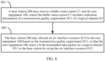
- an embodiment of this application provides a data transmission method, including: A base station receives a first buffer status report from first user equipment, where the first buffer status report includes indication information of a first transmission quality requirement, and the first transmission quality requirement is a transmission quality requirement of a first logical channel; and the base station allocates a first air interface resource to the first user equipment based on the first transmission quality requirement, so that the first user equipment sends a to-be-transmitted data packet on the first logical channel by using the first air interface resource.
- a buffer status report sent by user equipment may include the indication information of the transmission quality requirement of the first logical channel, so that the base station can allocate an air interface resource to the user equipment based on the transmission quality requirement.
- the user equipment can send the to-be-transmitted data packet on the first logical channel by using the air interface resource, so that uplink transmission quality of the to-be-transmitted data packet on the first logical channel is ensured, and communication experience of a user is improved.
- the method further includes: The base station receives a second buffer status report from second user equipment, where the second buffer status report includes indication information of a second transmission quality requirement; and the base station allocates a second air interface resource to the second user equipment based on the second transmission quality requirement, where when the second transmission quality requirement is lower than the first transmission quality requirement, and a buffer size in the second buffer status report is equal to a buffer size in the first buffer status report, there are fewer second air interface resources than the first air interface resource.
- the base station when a transmission quality requirement indicated by indication information in a buffer status report is relatively low, the base station allocates a relatively small quantity of resources to user equipment corresponding to the buffer status report; and when a transmission quality requirement indicated by indication information in a buffer status report is relatively high, the base station allocates a relatively large quantity of resources to user equipment corresponding to the buffer status report. In this way, uplink transmission quality of a data packet of user equipment with a relatively high transmission quality requirement is ensured, and communication experience of the user is improved.
- an embodiment of this application provides a data transmission apparatus, and the data transmission apparatus is configured on user equipment.
- the user equipment is configured with a first logical channel, and the first logical channel corresponds to a preset first transmission quality requirement.
- the apparatus includes: an obtaining unit, configured to obtain a first data packet generated by a first application, where the first application runs on the user equipment; a placement unit, configured to: when the first data packet carries a first identifier, use the first data packet as a to-be-transmitted data packet on the first logical channel, where the first identifier is used to indicate that the first data packet needs to be sent on an air interface based on the first transmission quality requirement; and a sending unit, configured to send a first buffer status report to a base station, where the first buffer status report includes indication information of the first transmission quality requirement, so that the base station allocates a first air interface resource to the first logical channel based on the first transmission quality requirement.
- the sending unit is further configured to send the to-be-transmitted data packet on
- the user equipment is configured with a second logical channel, and the second logical channel corresponds to no transmission quality requirement, or a transmission quality requirement corresponding to the second logical channel is lower than the first transmission quality requirement.
- the obtaining unit is further configured to obtain a second data packet generated by the first application.
- the placement unit is further configured to: when the second data packet does not carry the first identifier, use the second data packet as a to-be-transmitted data packet on the second logical channel.
- the sending unit is further configured to: when there is no to-be-transmitted data packet on the first logical channel and there is the to-be-transmitted data packet on the second logical channel, send a buffer status report corresponding to the second logical channel to the base station, so that the base station allocates a second air interface resource to the second logical channel.
- the sending unit is further configured to send the to-be-transmitted data packet on the second logical channel to the base station by using the second air interface resource.
- the first data packet and the second data packet belong to a same data flow.
- the first logical channel includes a plurality of channels
- the first transmission quality requirement includes a plurality of different transmission quality requirements
- channels in the plurality of channels and transmission quality requirements in the different transmission quality requirements are in a one-to-one correspondence
- the first identifier includes a transmission quality requirement identifier.
- the placement unit is further configured to determine, from the plurality of channels, a first channel that matches the transmission quality requirement identifier.
- the placement unit is further configured to use the first data packet as the to-be-transmitted data packet on the first channel.
- the first buffer status report is a short buffer status report medium access control control element (short BSR MAC CE).
- short BSR MAC CE medium access control control element
- the indication information is a message used to indicate a transmission quality requirement of the first channel, so that the base station allocates an air interface resource to the first channel based on the transmission quality requirement of the first channel.
- the non-empty channel is a channel with a to-be-transmitted data packet in the plurality of channels.
- the first buffer status report is a long buffer status report medium access control control element (long BSR MAC CE)
- the indication information includes information used to indicate a transmission quality requirement of the first channel and information used to indicate a transmission quality requirement of a second channel, so that the base station separately allocates air interface resources to the first channel and the second channel based on the transmission quality requirement of the first channel and the transmission quality requirement of the second channel.
- the first channel and the second channel are channels with the to-be-transmitted data packet in the plurality of channels.
- the first buffer status report includes a logical channel group identity (LCG ID) field, a buffer size field, and a transmission quality requirement indication information field.
- the indication information is a bit indicator in the transmission quality requirement indication information field.
- the base station is pre-configured with a correspondence between an identifier of the first logical channel and the first transmission quality requirement, and the indication information is the identifier of the first logical channel in the first buffer status report.
- the first transmission quality requirement includes a delay requirement and/or a bit error rate requirement.
- the data transmission apparatus provided in the third aspect is configured to perform the corresponding method provided in the first aspect. Therefore, for beneficial effects that can be achieved by the data transmission apparatus, refer to beneficial effects in the corresponding method provided in the first aspect. Details are not described herein again.
- an embodiment of this application provides a data transmission apparatus, including: a receiving unit, configured to receive a first buffer status report from first user equipment, where the first buffer status report includes indication information of a first transmission quality requirement, and the first transmission quality requirement is a transmission quality requirement of a first logical channel; and an allocation unit, configured to allocate a first air interface resource to the first user equipment based on the first transmission quality requirement, so that the first user equipment sends a to-be-transmitted data packet on the first logical channel by using the first air interface resource.
- the receiving unit is further configured to receive a second buffer status report from second user equipment, and the second buffer status report includes indication information of a second transmission quality requirement.
- the allocation unit is further configured to allocate a second air interface resource to the second user equipment based on the second transmission quality requirement.
- the data transmission apparatus provided in the fourth aspect is configured to perform the corresponding method provided in the second aspect. Therefore, for beneficial effects that can be achieved by the data transmission apparatus, refer to beneficial effects in the corresponding method provided in the second aspect. Details are not described herein again.
- an embodiment of this application provides user equipment, including a processor, a memory, and a transceiver.
- the memory is configured to store computer instructions.
- the processor executes the computer instructions, so that the user equipment performs the method provided in the first aspect.
- the user equipment provided in the fifth aspect is configured to perform the method provided in the first aspect. Therefore, for beneficial effects that can be achieved by the user equipment, refer to beneficial effects in the method provided in the first aspect. Details are not described herein again.
- an embodiment of this application provides a base station, including a processor, a memory, and a transceiver.
- the memory is configured to store computer instructions.
- the processor executes the computer instructions, so that the base station performs the method provided in the second aspect.
- the base station provided in the sixth aspect is configured to perform the method provided in the second aspect. Therefore, for beneficial effects that can be achieved by the base station, refer to beneficial effects in the method provided in the second aspect. Details are not described herein again.
- an embodiment of this application provides a computer storage medium.
- the computer storage medium includes computer instructions.
- the computer instructions When the computer instructions are run on an electronic device, the electronic device is enabled to perform the method provided in the first aspect or the method provided in the second aspect.
- an embodiment of this application provides a computer program product.
- program code included in the computer program product is executed by a processor in an electronic device, the method provided in the first aspect or the method provided in the second aspect is implemented.
- air interface scheduling in which a data packet is used as a granularity can be implemented, and an air interface resource can be applied for a data packet with an identifier based on a preset transmission quality requirement, so that uplink transmission quality of the data packet is ensured.
- an embodiment indicates that one or more embodiments of this application include a specific feature, structure, or characteristic described with reference to embodiments. Therefore, statements such as “in an embodiment”, “in some embodiments”, “in some other embodiments”, and “in other embodiments” that appear at different places in this specification do not necessarily mean referring to a same embodiment. Instead, the statements mean “one or more but not all of embodiments", unless otherwise specifically emphasized in another manner.
- A/B may represent A or B.
- and/or describes only an association relationship between associated objects and represents that three relationships may exist.
- a and/or B may represent the following three cases: Only A exists, both A and B exist, and only B exists.
- a plurality of means two or more.
- first and second are merely intended for description, and shall not be understood as an indication or implication of relative importance or implicit indication of a quantity of indicated technical features. Therefore, a feature limited by “first” or “second” may explicitly or implicitly include one or more features.
- the terms “include”, “comprise”, “have”, and their variants all mean “include but are not limited to”, unless otherwise specifically emphasized in another manner.
- an important data packet and a common data packet in a data flow there may be an important data packet and a common data packet in a data flow; in other words, different data packets belonging to a same data flow may have different importance.
- importance of a data packet corresponding to a walking action and importance of a data packet corresponding to an attack action are different.
- importance of an I frame and importance of a P frame are also different.
- the important data packet needs to be sent as soon as possible.
- data packets in a same data flow are sequentially sent in a sequence of generation time, and air interface resources allocated by a base station to an important data packet and a common data packet in a same data flow are the same.
- the important data packet may not be sent quickly or a sending success rate is relatively low, and consequently, communication experience of a user is poor.
- An embodiment of this application provides a data transmission method.
- User equipment may distinguish between an important data packet and a common data packet.
- the user equipment may use the important data packet as a to-be-transmitted data packet on an enhanced logical channel (LC), and the enhanced logical channel is configured with a relatively high transmission quality requirement (the transmission quality requirement may be preset).
- the user equipment may send a buffer status report (BSR) to a base station, and the buffer status report includes the transmission quality requirement of the enhanced logical channel, so that the base station may allocate an air interface resource to a data packet on the enhanced logical channel based on the transmission quality requirement; in other words, the base station may schedule the important data packet based on the transmission quality requirement.
- BSR buffer status report
- the data transmission method provided in this embodiment of this application may be applied to a wireless communication system shown in FIG. 1 , and the wireless communication system may include a base station 200 and a plurality of pieces of user equipment.
- the base station 200 may be specifically a generation NodeB (generation node B, gNB) in a fifth-generation (5G) mobile communication network (referred to as a 5G network for short below) system, an evolved NodeB (eNB or eNodeB) in a fourth-generation (4G) mobile communication network (referred to as a 4G network for short below) system, and a base station in another possible radio access technology.
- 5G fifth-generation
- eNB or eNodeB evolved NodeB
- 4G network fourth-generation
- the plurality of pieces of user equipment may include user equipment 100 and the like. Subsequently, the user equipment 100 is used as an example to describe the user equipment in this embodiment of this application.
- the user equipment 100 includes but is not limited to a mobile phone (mobile phone), a tablet computer (Pad), a computer with a wireless receiving/transmission function, a virtual reality (VR) terminal device, an augmented reality (AR) terminal device, a wireless terminal in industrial control, a wireless terminal in self-driving, a wireless terminal in remote medical, a wireless terminal in a smart grid, a wireless terminal in transportation safety, a wireless terminal in a smart city, a wireless terminal in a smart home, and the like.
- a mobile phone mobile phone
- a tablet computer Pad
- a computer with a wireless receiving/transmission function a virtual reality (VR) terminal device
- AR augmented reality
- a wireless terminal in industrial control a wireless terminal in self-driving
- a wireless terminal in remote medical a wireless terminal in a smart grid
- a wireless terminal in transportation safety a wireless terminal in a smart city, a wireless terminal in a smart home, and the like.
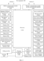
- FIG. 2 is a schematic diagram of a structure of the user equipment 100.
- the user equipment 100 may include a processor 110, an external memory interface 120, an internal memory 121, a universal serial bus (USB) port 130, a charging management module 140, a power management module 141, a battery 142, an antenna 1, an antenna 2, a mobile communication module 150, a wireless communication module 160, an audio module 170, a speaker 170A, a receiver 170B, a microphone 170C, a headset jack 170D, a sensor module 180, a button 190, a motor 191, an indicator 192, a camera 193, a display 194, a subscriber identification module (SIM) card interface 195, and the like.
- SIM subscriber identification module
- the sensor module 180 may include a pressure sensor 180A, a gyro sensor 180B, a barometric pressure sensor 180C, a magnetic sensor 180D, an acceleration sensor 180E, a distance sensor 180F, an optical proximity sensor 180G, a fingerprint sensor 180H, a temperature sensor 180J, a touch sensor 180K, an ambient light sensor 180L, a bone conduction sensor 180M, and the like.
- the structure shown in this embodiment of this application does not constitute a specific limitation on the user equipment 100.
- the user equipment 100 may include more or fewer components than those shown in the figure, combine some components, split some components, or have different component arrangements.
- the components shown in the figure may be implemented by hardware, software, or a combination of software and hardware.
- the processor 110 may include an application processor (AP) and a modem.
- AP application processor
- modem modem
- the processor 110 may further include one or more of a graphics processing unit (GPU), an image signal processor (ISP), a controller, a video codec, a digital signal processor (DSP), a baseband processor, a neural-network processing unit (NPU), and/or the like.
- GPU graphics processing unit
- ISP image signal processor
- DSP digital signal processor
- NPU neural-network processing unit
- Different processing units may be independent devices, or may be integrated into one or more processors.
- the controller may generate an operation control signal based on an instruction operation code and a time sequence signal, to complete control of instruction reading and instruction execution.
- a memory may be further disposed in the processor 110, and is configured to store instructions and data.
- the memory in the processor 110 is a cache.
- the memory may store instructions or data just used or is cyclically used by the processor 110. If the processor 110 needs to use the instructions or the data again, the processor may directly invoke the instructions or the data from the memory. This avoids repeated access, reduces waiting time of the processor 110, and improves system efficiency.
- a wireless communication function of the user equipment 100 may be implemented by using the antenna 1, the antenna 2, the mobile communication module 150, the wireless communication module 160, the modem, the baseband processor, and the like.
- the antenna 1 and the antenna 2 are configured to transmit and receive an electromagnetic wave signal.
- Each antenna in the user equipment 100 may be configured to cover one or more communication frequency bands. Different antennas may be further multiplexed, to improve antenna utilization.
- the antenna 1 may be multiplexed as a diversity antenna in a wireless local area network.
- an antenna may be used in combination with a tuning switch.
- the mobile communication module 150 may provide a solution for wireless communication including 2G/3G/4G/5G and the like applied to the user equipment 100.
- the mobile communication module 150 may include at least one filter, a switch, a power amplifier, a low noise amplifier (LNA), and the like.
- the mobile communication module 150 may receive an electromagnetic wave by using at least two antennas including the antenna 1, perform processing such as filtering and amplification on the received electromagnetic wave, and transmit the electromagnetic wave to the modem for demodulation.
- the mobile communication module 150 may further amplify a signal modulated by the modem, and convert an amplified signal into an electromagnetic wave through the antenna 1 for radiation.
- at least some functional modules in the mobile communication module 150 may be disposed in the processor 110.
- at least some functional modules of the mobile communication module 150 may be disposed in a same device as at least some modules of the processor 110.
- the modem may include a modulator and a demodulator.
- the modulator is configured to modulate a to-be-sent low-frequency baseband signal into a medium/high-frequency signal.
- the demodulator is configured to demodulate a received electromagnetic wave signal into a low-frequency baseband signal. Then, the demodulator transmits the low-frequency baseband signal obtained through demodulation to the baseband processor for processing.
- the baseband processor processes the low-frequency baseband signal, and then transfers an obtained signal to the application processor.
- the application processor outputs a sound signal by using an audio device (which is not limited to the speaker 170A, the receiver 170B, and the like), or displays an image or a video on the display 194.
- the modem may be an independent device.
- the modem may be independent of the processor 110, and is disposed in the same device as the mobile communication module 150 or another functional module.
- the mobile communication module 150 may be a module in the modem.
- the wireless communication module 160 may provide a wireless communication solution that is applied to the user equipment 100, and that includes a wireless local area network (WLAN) (for example, a wireless fidelity (Wi-Fi) network), Bluetooth (BT), a global navigation satellite system (GNSS), frequency modulation (FM), a near field communication (NFC) technology, an infrared (IR) technology, or the like.
- WLAN wireless local area network
- BT Bluetooth
- GNSS global navigation satellite system
- FM frequency modulation
- NFC near field communication
- IR infrared
- the wireless communication module 160 may be one or more devices integrating at least one communication processing module.
- the wireless communication module 160 receives an electromagnetic wave through the antenna 2, performs frequency modulation and filtering processing on an electromagnetic wave signal, and sends a processed signal to the processor 110.
- the wireless communication module 160 may further receive a to-be-sent signal from the processor 110, perform frequency modulation and amplification on the signal, and convert the signal into an electromagnetic wave for radiation through the antenna 2.
- the antenna 1 and the mobile communication module 150 in the user equipment 100 are coupled, and the antenna 2 and the wireless communication module 160 in the user equipment 100 are coupled, so that the user equipment 100 can communicate with a network and another device by using a wireless communication technology.
- the wireless communication technology may include a global system for mobile communication (GSM), a general packet radio service (GPRS), code division multiple access (CDMA), wideband code division multiple access (WCDMA), time-division code division multiple access (TD-SCDMA), long term evolution (LTE), a fifth generation, new radio (NR), BT, a GNSS, a WLAN, NFC, FM, an IR technology, and/or the like.
- the GNSS may include a global positioning system (GPS), a global navigation satellite system (GLONASS), a BeiDou navigation satellite system (BDS), a quasi-zenith satellite system (QZSS), and/or satellite based augmentation systems (SBAS).
- GPS global positioning system
- GLONASS global navigation satellite system
- BDS BeiDou navigation satellite system
- QZSS quasi-zenith satellite system
- SBAS satellite based augmentation systems
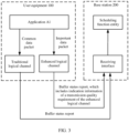
- FIG. 3 is a diagram of a system architecture of a data transmission method according to an embodiment of this application.
- an application A1 may be installed on user equipment 100.
- the application A1 may be a game application, such as a MOBA game application or an augmented reality (AR) game.
- the application A1 may alternatively be an instant messaging application. Details are not listed herein one by one.
- the application A1 may be a system built-in application of the user equipment 100.
- the application A1 may alternatively be a third-party application. For example, a user downloads the third-party application from an application market and installs the third-party application, and the user may further uninstall the third-party application.
- the application A1 is not specifically limited in this embodiment of this application.
- the application A1 may classify data packets generated by the application A1 into an important data packet and a normal data packet.
- a manner of determining the important data packet and the common data packet is described below, and details are not described herein again.
- the important data packet needs to be sent by using an air interface in a timely manner. In other words, time urgency for sending the important data packet by using the air interface is higher than that of the common data packet.
- a conventional logical channel and an enhanced logical channel may be disposed on the user equipment 100, and the conventional logical channel and the enhanced logical channel separately belong to different logical channel groups (LCG).
- the enhanced logical channel may also be referred to as a high-priority logical channel, and is a logical channel that is configured in this embodiment of this application and that corresponds to a specific transmission quality requirement.
- the specific transmission quality requirement may be preset. A manner of representing the transmission quality requirement is specifically described below, and details are not described herein again.
- the conventional logical channel corresponds to no transmission quality requirement or corresponds to a relatively low transmission quality requirement (lower than the transmission quality requirement corresponding to the enhanced logical channel).
- the important data packet may be placed on the enhanced logical channel as a to-be-transmitted packet on the enhanced logical channel.
- the common packet may be placed on the conventional logical channel as a to-be-transmitted packet on the conventional logical channel.
- the user equipment 100 may send a buffer status report (BSR) corresponding to the enhanced logical channel to a base station 200.
- BSR buffer status report
- the buffer status report includes indication information, and the indication information is used to indicate the transmission quality requirement corresponding to the enhanced logical channel.
- a specific implementation form of the indication information is specifically described below, and details are not described herein again.
- the base station 200 may receive the buffer status report through a receiving interface, and transfer the buffer status report to a scheduling function entity of the base station 200, so that the scheduling function entity may allocate an air interface resource to the user equipment 100 based on the transmission quality requirement corresponding to the enhanced logical channel.
- the scheduling function entity may be a medium access control (MAC) entity.
- MAC medium access control
- the user equipment 100 may send a buffer status report corresponding to the conventional logical channel to the base station 200.
- the buffer status report is a conventional buffer status report, and does not carry indication information used to indicate a transmission quality requirement. Therefore, when allocating an air interface resource, the base station 200 does not need to take the transmission quality requirement of the conventional logical channel into consideration.
- the base station when the base station simultaneously allocates air interface resources to the plurality of pieces of user equipment including the user equipment 100, if a buffer status report sent by another piece of user equipment other than the user equipment 100 includes the indication information used to indicate the transmission quality requirement, the base station may preferentially allocate the air interface resource to the another piece of user equipment, to preferentially schedule an important data packet in the another piece of user equipment.
- the user equipment 100 is used as an example to describe an implementation solution, on a user equipment side, of the data transmission method provided in this embodiment of this application.
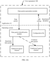
- FIG. 4A is a schematic diagram of a software structure of the user equipment 100.
- the user equipment 100 may be configured with an enhanced logical channel and a conventional logical channel.
- the enhanced logical channel is a configured logical channel corresponding to a preset transmission quality requirement.
- the transmission quality requirement corresponding to the enhanced logical channel may include a delay requirement.
- a delay is less than 5 ms, or a delay is between 5 ms and 10 ms.
- the transmission quality requirement corresponding to the enhanced logical channel may include a bit error rate requirement.
- a bit error rate needs to be converged to 10 -6 .
- the transmission quality requirement corresponding to the enhanced logical channel may include a delay requirement and a bit error rate requirement. Details are not listed herein one by one.
- the transmission quality requirement corresponding to the enhanced logical channel may be set based on experience or experiments.
- the conventional logical channel corresponds to no transmission quality requirement, or is a configured logical channel corresponding to a relatively low transmission quality requirement (lower than the transmission quality requirement corresponding to the enhanced logical channel).
- An important data packet generated by the application A1 may be placed on the enhanced logical channel as a to-be-transmitted data packet on the enhanced logical channel, so that when applying for uplink scheduling, the base station may allocate an air interface resource to the important data packet based on the transmission quality requirement of the enhanced logical channel, to ensure uplink transmission quality and preferential sending of the important data packet. Details are described below, and are not described herein again.
- the application A1 may include a data packet generation module.
- the data packet generation module may run related data based on the application A1 to generate a data packet.
- the application A1 may be set to a MOBA game application, and may generate a data packet in response to a game operation of the user.
- the user may touch a "walking" functional area to control a game character to walk on a path, and the application A1 may generate a data packet in response to the user's operation of touching the "walking" functional area.
- the user may touch an "attack" functional area to control a game character to make an attack, and the application A1 may generate a data packet in response to the user's operation of touching the "attack” functional area.
- the application A1 may be set to an instant messaging application. During a video call of the application A1, the application A1 may generate a video data flow. Each video frame in the video data flow may be referred to as a data packet.
- the data packet generation module may determine, based on characteristic information of the data packet, whether the data packet is an important data packet.
- the data packet may be a data packet generated by the application A1 in response to an operation of the user.
- the application A1 may determine, based on a functional area in which the operation works, whether the data packet is an important data packet.
- the characteristic information of the data packet may be information used to represent the functional area. It may be understood that a functional area of an application is a virtual key on an application interface, and a touch operation performed on the virtual key may trigger the application to generate a response, for example, generate a data packet.
- a developer or a designer of the application A1 may preset an important functional area, and set, to an important data packet, a data packet triggered by an operation performed on the important functional area, that is, set, to an important data packet, a data packet generated by the application A1 in response to the operation performed on the important functional area.
- a developer of a game application may set an attack launching functional area such as "attack”, “shoot”, or “slide tackle” to an important functional area, and set another functional area to a common functional area.
- a developer of a payment application may set a functional area such as "confirm to pay" used to trigger a payment procedure to an important functional area, and set another functional area to a common functional area. Selection of the important functional area is not described herein.
- a developer of the application may choose, based on experience or experiments, to set one or more functional areas on a running interface of the application to important functional areas.
- a data packet generated by the application A1 when being triggered by an operation performed on the important functional area may be determined as the important data packet by the application A, and a data packet generated by the application A1 when being triggered by an operation performed on the common functional area may be determined as the common data packet by the application A.
- a data packet of a type of a video frame may be divided into an I frame and a P frame.
- the I frame is a key frame, and during decoding, only data of a current frame is required to generate a complete picture.
- the P frame does not include complete picture data, and during decoding, data of a previous frame needs to be used to generate complete picture data. Therefore, the I frame is more important than the P frame, and may be determined as the important data packet.
- Information used to indicate a specific type of frame of the data packet may be referred to as characteristic information of the data packet.
- characteristic information indicating that the data packet is the I frame may be referred to as characteristic information of the I frame
- information indicating that the data packet is the P frame may be referred to as characteristic information of the P frame.
- a data packet is an important data packet may be determined based on characteristic information (for details, refer to the descriptions above) of a data packet layer of the data packet, instead of being determined based on information at a data flow layer. Therefore, the important data packet and the common data packet may belong to a same data flow.
- the application A1 may add an importance identifier to the important data packet.
- the importance identifier is used to indicate that a data packet that carries the importance identifier needs to be sent on an air interface based on a relatively high transmission quality requirement.
- a configuration file may be preset in an operating system of the user equipment 100, and the configuration file may be configured with an importance identifier.
- the importance identifier may indicate that a data packet that carries the importance identifier needs to be sent on an air interface based on the transmission quality requirement of the enhanced logical channel.
- the importance identifier may be a preset bit string.
- the data packet generation module may obtain the importance identifier in the configuration file by invoking an application programming interface (API), and add the importance identifier to the important data packet.
- API application programming interface
- a method setPriority may be added to a class HtttpURLConnection, so that the application A1 may invoke the method to add the importance identifier to the important data packet.
- the configuration file in the operating system may further include important data packet recommendation information.
- the important data packet recommendation information may include a plurality of data packet types.
- the plurality of data packet types may include a data packet of a self-driving service generated when a driving speed is greater than 60 km/h, a data packet of an attack action in an AR game or a MOBA game, and a data packet of an intelligent transportation service in a preset time period (such as rush hour). It may be understood that these types of data packets are relatively important and need to be transmitted in a timely and high-quality manner.
- the data packet generation module of the application A1 may view the important data packet recommendation information in the configuration file by invoking the API, and determine whether the data packet generated by the data packet generation module belongs to one of the foregoing plurality of data packet types. If the data packet generated by the data packet generation module belongs to one of the foregoing plurality of data packet types, the data packet generation module may determine the data packet generated by the data packet generation module as an important data packet, and add the importance identifier to the data packet.
- the application A1 may transfer the data packet generated by the application A1 to the operating system of the user equipment 100.
- the operating system may be configured with a data packet identification module.
- the data packet identification module may identify whether a data packet received from the application A1 is an important data packet. As described above, when the data packet carries the importance identifier, the data packet identification module may identify the data packet as an important data packet; and when the data packet does not carry the importance identifier, the data packet identification module may identify the data packet as a common data packet.
- the data packet identification module may be an internet protocol (internet protocol, IP) stack.
- IP internet protocol
- the IP stack may be configured to parse the data packet and detect whether the data packet carries the importance identifier.
- whether the data packet received from the application A1 is an important data packet or a common data packet may be identified by using the data packet identification module.
- the operating system may place the data packet on the enhanced logical channel, so that the data packet is used as a to-be-transmitted data packet on the enhanced logical channel.
- the operating system may place the data packet on the conventional logical channel, so that the data packet is used as a to-be-transmitted data packet on the conventional logical channel.
- the user equipment 100 may send a buffer status report to the base station 200.
- a buffer status report corresponding to the enhanced logical channel may include indication information, and the indication information is used to indicate the transmission quality requirement corresponding to the enhanced logical channel.
- the buffer status report in this embodiment of this application is specifically described below, and details are not described herein again.
- FIG. 4B is a schematic diagram of another software structure of the user equipment 100.
- the user equipment 100 may be configured with an enhanced logical channel and a conventional logical channel.
- the enhanced logical channel is a configured logical channel corresponding to a preset transmission quality requirement.
- the conventional logical channel corresponds to no transmission quality requirement, or is a configured logical channel corresponding to a relatively low transmission quality requirement (lower than the transmission quality requirement corresponding to the enhanced logical channel).
- the enhanced logical channel may include a plurality of logical channels, and different logical channels in the plurality of logical channels respectively correspond to different transmission quality requirements.
- a transmission quality requirement corresponding to each logical channel may be preset.
- a logical channel in the plurality of logical channels may be referred to as an enhanced sub-channel.
- the enhanced logical channel may include an enhanced sub-channel B1, an enhanced sub-channel B2, and the like.
- a transmission quality requirement corresponding to the enhanced sub-channel B1 is different from a transmission quality requirement corresponding to the enhanced sub-channel B2.
- the enhanced logical channel may specifically include eight enhanced sub-channels, and different enhanced sub-channels correspond to different transmission quality requirements.
- the user equipment 100 may be configured a plurality of transmission quality requirement identifiers, and transmission quality requirement identifiers in the plurality of transmission quality requirement identifiers may be in a one-to-one correspondence with transmission quality requirements of the enhanced sub-channels in the enhanced logical channel.
- the transmission quality requirement identifier may be a bit string of 3 bits, and transmission quality requirement identifiers corresponding to different transmission quality requirements are obtained by setting bit values at different locations in the bit string.
- a configuration file may be pre-configured in an operating system.
- the configuration file may include the foregoing plurality of transmission quality requirement identifiers and a transmission quality requirement corresponding to each of the plurality of transmission quality requirement identifiers.
- the configuration file may further include data packet types that are suitable for or match different transmission quality requirements.
- the configuration file may be shown in Table 1. In Table 1, the transmission quality requirement identifier is represented by using a bit string of 3 bits, and the transmission quality requirement is represented by using a delay and a bit error rate.
- Table 1 Transmission quality requirement identifier Transmission quality requirement Example of a data packet type Bit 2 Bit 1 Bit 0 Delay (ms) Bit error rate 0 0 0 5 10 -6 Data packet of a self-driving service generated when a driving speed is greater than 60 km/h 0 0 1 8 10 -6 Data packet of an attack action in an AR game or a MOBA game 0 1 0 3 10 -5 Data packet of a high-voltage monitoring service in bad weather 0 1 1 25 10 -5 Data packet of an intelligent transportation service within a preset time period (such as rush hour) 1 0 0 9 10 -4 Distributed automation control information 1 0 1 9 10 -4 Distributed automation maintenance information 1 1 0 20 10 -4 Data packet generated by a payment operation 1 1 1 10 10 -3 I frame of a video when frame freezing occurs during play of the video
- the application A1 may include a data generation module.
- the data generation module may generate a data packet.
- the data generation module may generate a data packet.
- the data generation module may access the configuration file by invoking an API, check and select the transmission quality requirement, and add a transmission quality requirement identifier corresponding to the selected transmission quality requirement to the generated data packet. For example, the data generation module may check data packet types that are suitable for or match different transmission quality requirements, and determine a data packet type to which the currently generated data packet belongs. Therefore, a transmission quality requirement that is suitable for or matches the currently generated data packet may be determined, and further, a transmission quality requirement identifier corresponding to the transmission quality requirement may be added to the currently generated data packet.
- the transmission quality requirement identifier may be considered as an importance identifier.
- the transmission quality requirement identifier is also the importance identifier.
- the data packet generation module may alternatively not add any transmission quality requirement identifier to the currently generated data packet; in other words, the application A1 may not specifically require transmission quality of the currently generated data packet.
- the application A1 may transfer the data packet to a data packet identification module in the operating system.
- the data packet identification module identifies whether the data packet carries a transmission quality requirement identifier.
- the data packet identification module places the data packet on the conventional logical channel, so that the data packet is used as a to-be-transmitted data packet on the conventional logical channel.
- the data packet identification module may place the data packet on an enhanced sub-channel corresponding to the transmission quality requirement identifier based on a correspondence between the transmission quality requirement identifier and the enhanced sub-channel. For example, the data packet carries a transmission quality requirement identifier B11, and the transmission quality requirement identifier B11 corresponds to an enhanced sub-channel B1. Therefore, the data packet identification module may place the data packet on the enhanced sub-channel B1, so that the data packet is used as a to-be-transmitted data packet on the enhanced sub-channel B1.
- the user equipment may send a buffer status report to the base station, to request the base station to allocate an air interface resource to the user equipment.
- the buffer status report may include an identifier of the logical channel, to indicate a specific logical channel whose buffer status is reported in the buffer status report.
- the identifier of the logical channel may be a logical channel group identity (logical channel group identity, LCG ID) of the logical channel.
- the enhanced logical channel and the conventional logical channel in the embodiment shown in FIG. 4A and the enhanced sub-channel and the conventional logical channel in the embodiment shown in FIG. 4B may be collectively referred to as the logical channel, or all belong to the logical channel.
- the buffer status report used in this embodiment of this application may be a short buffer status report medium access control control element (short BSR MAC CE).
- short BSR MAC CE short buffer status report medium access control control element
- FIG. 5A shows a structure of a conventional short buffer status report medium access control control element.
- a length of the conventional short buffer status report medium access control control element is one byte (Oct)
- the conventional short buffer status report medium access control control element includes a logical channel group identity field and a buffer size field.
- the user equipment when sending the buffer status report corresponding to the conventional logical channel, may send the conventional short buffer status report medium access control control element.
- a group identity of a logical channel group to which the conventional logical channel belongs may be filled in the logical channel group identity field, and a buffer data amount in the conventional logical channel may be filled in the buffer size field.
- FIG. 5B shows a structure of an enhanced short buffer status report medium access control control element.
- the enhanced short buffer status report medium access control control element includes a logical channel group identity field, a buffer size field, and a transmission quality requirement indication information field.
- the enhanced short buffer status report medium access control control element is obtained based on a conventional buffer status report medium access control control element.
- the conventional short buffer status report medium access control control element and the enhanced short buffer status report medium access control control element may be collectively referred to as a short buffer status report medium access control control element.
- the user equipment may send the enhanced short buffer status report medium access control control element.
- a group identity of a logical channel group to which the enhanced logical channel belongs may be filled in the logical channel group identity field
- a buffer data amount in the enhanced logical channel may be filled in the buffer size field
- indication information of a transmission quality requirement corresponding to the enhanced logical channel may be filled in the transmission quality requirement indication information field.
- the indication information of the transmission quality requirement may be pre-agreed on by the user equipment and the base station, and can represent information about the transmission quality requirement corresponding to the enhanced logical channel, for example, may be a specific bit string.
- a transmission quality requirement represented by a bit string "000" may be set as follows: A delay is less than 5 ms, and a bit error rate is less than 10 -6 .
- the indication information of the transmission quality requirement may be a transmission quality requirement identifier corresponding to the transmission quality requirement.
- the user equipment may send the enhanced short buffer status report medium access control control element.
- a group identity of a logical channel group to which the enhanced sub-channel belongs may be filled in the logical channel group identity field
- a buffer data amount in the enhanced sub-channel may be filled in the buffer size field
- indication information of a transmission quality requirement corresponding to the enhanced sub-channel may be filled in the transmission quality requirement indication information field.
- indication information of the transmission quality requirement may be pre-agreed on by the user equipment and the base station, and can represent information about the transmission quality requirement corresponding to the enhanced sub-channel.
- a correspondence between the indication information and a transmission quality requirement represented by the indication information is stored on a base station side.
- the indication information of the transmission quality requirement may be a specific bit string.
- the indication information of the transmission quality requirement may be bit indication information.
- a transmission quality requirement represented by a bit string "000" may be set as follows: A delay is less than 5 ms, and a bit error rate is less than 10 -6 .
- the indication information of the transmission quality requirement may be a transmission quality requirement identifier corresponding to the transmission quality requirement.
- the buffer status report of the enhanced logical channel may alternatively be the conventional short buffer status report medium access control control element.
- the enhanced logical channel (or the enhanced sub-channel) has a fixed logical channel group identity, and a correspondence between a logical channel group identity and a transmission quality requirement may be pre-configured on the base station side.
- the base station may determine, based on a logical channel group identity in the buffer status report by using the correspondence between a logical channel group identity and a transmission quality requirement, whether the buffer status report corresponds to the transmission quality requirement.
- an air interface resource may be allocated to the user equipment based on the transmission quality requirement. Details are described below, and are not described herein again.
- the user equipment 100 may send the buffer status report of the enhanced logical channel to the base station 200.
- the user equipment 100 may first send the buffer status report of the enhanced logical channel, to preferentially schedule the to-be-transmitted data packet on the enhanced logical channel.
- the user equipment 100 may send the conventional short buffer status report medium access control control element to the base station 200.
- the user equipment 100 may send the buffer status report of the enhanced sub-channel to the base station 200.
- buffer status reports may be sequentially sent based on transmission quality requirements corresponding to the plurality of enhanced sub-channels.
- a buffer status report of an enhanced sub-channel with a highest transmission quality requirement is sent first; and then, a buffer status report of an enhanced sub-channel with a second highest transmission quality requirement is sent; and so on.
- a buffer status report of the conventional logical channel with the to-be-transmitted data packet is not sent until buffer status reports of all enhanced sub-channels with the to-be-transmitted data packet are sent.
- the buffer status report used in this embodiment of this application may be a long buffer status report medium access control control element (long BSR MAC CE).
- long BSR MAC CE long buffer status report medium access control control element
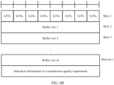
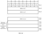
- FIG. 6A shows a structure of a conventional long buffer status report medium access control control element.
- a logical channel group identity may be represented by three consecutive bits. Therefore, a maximum of eight logical channel group identities can be written to a first byte (byte 1) of the long buffer status report medium access control control element.
- buffer statuses of a maximum of eight logical channels may be simultaneously reported in one buffer status report. It may be understood that, for one piece of user equipment, logical channels configured by the user equipment or logical channels simultaneously having the to-be-transmitted data packet generally have no more than eight pieces of data. Therefore, the long buffer status report medium access control control element may simultaneously buffer statuses of all the logical channels with the to-be-transmitted data packet.
- the user equipment when sending the buffer status report corresponding to the conventional logical channel, may send the conventional long buffer status report medium access control control element.
- Three consecutive bits (such as bits corresponding to an LCG 0 ) in the byte 1 may be filled with a group identity of a logical channel group to which the conventional logical channel belongs (other bits in the byte 1 are not filled), and a corresponding buffer size field may be filled with a buffer data amount in the conventional logical channel.
- FIG. 6B shows a structure of an enhanced conventional long buffer status report medium access control control element.
- the structure of the enhanced conventional long buffer status report medium access control control element shown in FIG. 6B is obtained by adding a transmission quality requirement indication information field to the structure of the conventional long buffer status report medium access control control element.
- the conventional long buffer status report medium access control control element and the enhanced long buffer status report medium access control control element may be collectively referred to as a long buffer status report medium access control control element.
- the user equipment may send the enhanced long buffer status report medium access control control element.
- Three consecutive bits (such as bits corresponding to an LCG 0 ) in the byte 1 may be filled with a group identity of a logical channel group to which the enhanced logical channel belongs (other bits in the byte 1 are not filled), a corresponding buffer size field may be filled with a buffer data amount in the enhanced logical channel, and the transmission quality requirement indication information field may be filled with indication information of the transmission quality requirement corresponding to the enhanced logical channel.
- the indication information of the transmission quality requirement may be pre-agreed on by the user equipment and the base station, and can represent information about the transmission quality requirement corresponding to the enhanced logical channel, for example, may be a specific bit string.
- a transmission quality requirement represented by a bit string "000" may be set as follows: A delay is less than 5 ms, and a bit error rate is less than 10 -6 .
- the user equipment when sending the buffer status report corresponding to the enhanced sub-channel shown in FIG. 4B , may send the enhanced long buffer status report medium access control control element.
- the enhanced long buffer status report medium access control control element may report a buffer status of the enhanced sub-channel.
- three consecutive bits (such as bits corresponding to an LCG 0 ) in the byte 1 may be filled with a group identity of a logical channel group to which the enhanced sub-channel belongs (other bits in the byte 1 are not filled)
- a corresponding buffer size field may be filled with a buffer data amount in the enhanced sub-channel
- the transmission quality requirement indication information field may be filled with indication information of a transmission quality requirement corresponding to the enhanced sub-channel.
- the enhanced long buffer status report medium access control control element may report buffer statuses of the two or more enhanced sub-channels.
- three consecutive bits (such as bits corresponding to an LCG 0 ) in the byte 1 may be filled with a group identity of a logical channel group to which one of the enhanced sub-channels belongs, other three consecutive bits (such as bits corresponding to an LCG 1 ) may be filled with a group identity of a logical channel group to which another enhanced sub-channel belongs, and so on, until group identities of logical channel groups to which the two or more enhanced sub-channels belong are filled into the byte 1.
- a corresponding buffer size field is filled with a buffer data amount in the enhanced sub-channel.
- a corresponding location in the transmission quality requirement indication information field is filled with indication information of a transmission quality requirement corresponding to the enhanced sub-channel.
- a location (or a ranking), in the transmission quality requirement indication information field, of indication information of a transmission quality requirement corresponding to an enhanced sub-channel is consistent with a location (or a ranking), in the byte 1, of a group identity of a logical channel group to which the enhanced sub-channel belongs. Therefore, when receiving the enhanced long buffer status report medium access control control element, the base station may learn the transmission quality requirement of the enhanced sub-channel indicated by the logical channel group identity.
- the indication information of the transmission quality requirement may be pre-agreed on by the user equipment and the base station, and can represent information about the transmission quality requirement corresponding to the enhanced logical channel, for example, may be a specific bit string.
- a transmission quality requirement represented by a bit string "000" may be set as follows: A delay is less than 5 ms, and a bit error rate is less than 10 -6 .
- the indication information of the transmission quality requirement may be a transmission quality requirement identifier corresponding to the transmission quality requirement.
- a size of the transmission quality requirement indication information field may be dynamically set based on a quantity of enhanced sub-channels reported by the enhanced long buffer status report medium access control control element.
- the indication information of the transmission quality requirement is a bit string of 3 bits.
- a size of the transmission quality requirement indication information field in the enhanced long buffer status report medium access control control element is 3 bits; when the enhanced long buffer status report medium access control control element reports two enhanced sub-channels, the size of the transmission quality requirement indication information field in the enhanced long buffer status report medium access control control element is 6 bits; and so on.
- the quantity of enhanced sub-channels reported by the enhanced long buffer status report medium access control control element is directly proportional to the size of the transmission quality requirement indication information field in the enhanced long buffer status report medium access control control element.
- the quantity of enhanced sub-channels reported by the enhanced long buffer status report medium access control control element may be set to 8, and in this case, three bytes
- the transmission quality requirement indication information field may be 24 bytes in size, and can be filled with indication information of a transmission quality requirement corresponding to each enhanced sub-channel.
- the enhanced long buffer status report medium access control control element may be used to report the indication information of the transmission quality requirement of the enhanced logical channel or the enhanced sub-channel to the base station.
- the buffer status report of the enhanced logical channel may alternatively be the conventional long buffer status report medium access control control element.
- the enhanced logical channel (or the enhanced sub-channel) has a fixed logical channel group identity, and a correspondence between a logical channel group identity and a transmission quality requirement may be pre-configured on the base station side.
- the base station may determine, based on a logical channel group identity in the buffer status report by using the correspondence between a logical channel group identity and a transmission quality requirement, whether the buffer status report corresponds to the transmission quality requirement.
- an air interface resource may be allocated to the user equipment based on the transmission quality requirement. Details are described below, and are not described herein again.
- attribute configuration may be added to the base station side in the following code:
- logicalChannelDelay represents a delay requirement of the logical channel. For example, ms0 represents a delay that is less than 5 ms, and ms5 represents a delay that is between 5 ms and 10 ms.
- logicalChannelPER represents a bit error rate requirement of the logical channel. For example, 10 -6 represents that a bit error rate needs to be converged to 10 -6 .
- the base station may allocate, based on the configured "logicalChannelDelay” and "logicalChannelPER", an air interface resource to a logical channel corresponding to the long buffer status report medium access control control element.
- the user equipment 100 may send the buffer status report of the enhanced logical channel to the base station 200.
- the user equipment 100 may first send the buffer status report of the enhanced logical channel, to preferentially schedule the to-be-transmitted data packet on the enhanced logical channel.
- the user equipment 100 may send the conventional short buffer status report medium access control control element to the base station 200.
- the user equipment 100 may send a buffer status report used to simultaneously report buffer statuses of the one or more enhanced sub-channels to the base station 200.
- the user equipment 100 may send the conventional long buffer status report medium access control control element to the base station 200.
- the user equipment may send, to the base station, a buffer status report that carries indication information of a transmission quality requirement, so that the base station may allocate an air interface resource to the user equipment based on the transmission quality requirement, to implement preferential scheduling.
- the user equipment may include an application, an operating system (OS) module, an IP protocol processing module, a plurality of enhanced sub-channels, and a sending interface.
- OS operating system
- IP protocol processing module IP protocol processing module
- the application may generate a data packet, and may add a transmission quality requirement identifier to an important data packet. No transmission quality requirement identifier is added to a common data packet.
- the application transfers, to the OS module, the data packet that carries the transmission quality requirement identifier.
- the OS module may include an IP functional entity, and may package the data packet based on an IP layer protocol.
- the IP functional entity may package the transmission quality requirement identifier into an IP header of the data packet.
- the transmission quality requirement identifier may be a bit string with a length of 3 bits. Three bits may be selected from an Options field in the IP header to fill in the transmission quality requirement identifier.
- the OS module may transfer a processed data packet to the IP protocol processing module.
- the IP protocol processing module may parse the IP header of the data packet, extract the transmission quality requirement identifier of the IP header, and place the data packet on a corresponding enhanced sub-channel based on a correspondence between a transmission quality requirement identifier and an enhanced sub-channel, to use the data packet as a to-be-transmitted data packet on the enhanced sub-channel.
- the IP protocol processing module may parse the IP header of the data packet, extract the transmission quality requirement identifier of the IP header, and place the data packet on a corresponding enhanced sub-channel based on a correspondence between a transmission quality requirement identifier and an enhanced sub-channel, to use the data packet as a to-be-transmitted data packet on the enhanced sub-channel.
- An enhanced sub-channel B 1, an enhanced sub-channel B2, and an enhanced sub-channel B3 may be set to simultaneously have to-be-transmitted data packets, and a transmission quality requirement of the enhanced sub-channel B3 > a transmission quality requirement of the enhanced sub-channel B2 > a transmission quality requirement of the enhanced sub-channel B1.
- the sending interface may first send a buffer status report of the enhanced sub-channel B3, then send a buffer status report of the enhanced sub-channel B2, and finally send a buffer status report of the enhanced sub-channel B1, so that an air interface resource may be allocated to the enhanced sub-channel B3 before the enhanced sub-channel B2 and the enhanced sub-channel B1, and an air interface resource may be allocated to the enhanced sub-channel B2 before the enhanced sub-channel B1.
- the to-be-transmitted data packet on the enhanced sub-channel B3 is sent first, then the to-be-transmitted data packet on the enhanced sub-channel B2 is sent, and the to-be-transmitted data packet on the enhanced sub-channel B3 is sent at last.
- an air interface resource may be preferentially applied for an important data packet through air interface scheduling in which a data packet is used as a granularity, so that timely sending of the important data packet is ensured.
- air interface scheduling in which a data packet is used as a granularity is implemented, and an air interface resource can be applied for the important data packet based on a preset transmission quality requirement, so that uplink transmission quality of the important data packet is ensured. Further, the air interface resource can be preferentially applied for the important data packet, so that timely sending of the important data packet is ensured.
- the solution may include the following steps.
- Step 801 The base station 200 may receive a buffer status report C1 sent by the user equipment 100.
- the buffer status report C1 includes indication information of a transmission quality requirement D11 of a logical channel D1.
- the logical channel D1 is a logical channel of the user equipment 100, and may be specifically the enhanced logical channel in the embodiment shown in FIG. 4A , or the enhanced sub-channel in the embodiment shown in FIG. 4B .
- the buffer status report C1 may be an enhanced short buffer status report medium access control control element or an enhanced long buffer status report medium access control control element.
- the indication information of the transmission quality requirement D11 may be information filled in a transmission quality requirement indication information field in the enhanced short buffer status report medium access control control element or the enhanced long buffer status report medium access control control element.
- the base station 200 may determine the transmission quality requirement D11 based on a pre-configured correspondence between indication information of a transmission quality requirement and the transmission quality requirement by using the indication information of the transmission quality requirement D11.
- the buffer status report C1 may be a conventional short buffer status report medium access control control element or a conventional long buffer status report medium access control control element.
- the indication information of the transmission quality requirement D11 may be a logical channel group identity of the logical channel D1.
- the base station 200 may determine the transmission quality requirement D11 based on a pre-configured correspondence between a logical channel group identity and a transmission quality requirement by using the logical channel group identity of the logical channel D1.
- Step 803 The base station 200 may allocate an air interface resource D12 to the user equipment 100 based on the transmission quality requirement D11, so that the user equipment 100 sends a to-be-transmitted data packet on the logical channel D11 to the base station by using the air interface resource D12. In this way, actual transmission quality of the to-be-transmitted data packet on the logical channel D11 can reach or be close to the transmission quality requirement D11.
- the base station 200 may allocate a relatively large quantity of air interface resources to user equipment with a relatively high transmission quality requirement.
- the base station 200 may further receive a buffer status report C2 from user equipment E1, and the buffer status report C2 includes indication information of a transmission quality requirement D21 of a logical channel D2.
- the logical channel D2 is a logical channel of the user equipment E1, and may be specifically the enhanced logical channel in the embodiment shown in FIG. 4A , or the enhanced sub-channel in the embodiment shown in FIG. 4B .
- the user equipment E1 is user equipment different from the user equipment 100.
- the base station 200 may determine the transmission quality requirement D21 based on the indication information of the transmission quality requirement D21.
- the base station 200 may also allocate an air interface resource D22 to the user equipment E1 based on the transmission quality requirement D21.
- the transmission quality requirement D21 is lower than the transmission quality requirement D11, when another condition is the same or similar (for example, a buffer size in the buffer status report C2 is equal to a buffer size in the buffer status report C1), more air interface resources may be allocated to the user equipment 100; in other words, there are more air interface resources D12 than the air interface resource D22.
- the base station 200 may further receive a buffer status report C3 from user equipment E2.
- the buffer status report C3 may be used to report a buffer status of the conventional logical channel shown in FIG. 4A or FIG. 4B .
- the buffer status report C3 does not include indication information of a transmission quality requirement.
- the base station 200 When allocating the air interface resource to the user equipment 100 based on the transmission quality requirement D11, the base station 200 also allocates an air interface resource D32 to the user equipment E2.
- a buffer size in the buffer status report C3 is equal to a buffer size in the buffer status report C1
- more air interface resources may be allocated to the user equipment 100; in other words, there are more air interface resources D12 than the air interface resource D32.
- the user equipment E2 is user equipment different from the user equipment 100.
- buffer status report C1 is a long buffer status report medium access control control element
- buffer statuses of a plurality of enhanced sub-channels may be reported in the buffer status report C1.
- the enhanced sub-channel refer to the descriptions of the embodiment shown in FIG. 4B .
- the buffer status report C1 may be set to report a buffer status of an enhanced sub-channel d1 and a buffer status of an enhanced sub-channel d2. Accordingly, the buffer status report C1 includes indication information of a transmission quality requirement d11 of the enhanced sub-channel d1 and indication information of a transmission quality requirement d21 of the enhanced sub-channel d2.
- the base station 200 may allocate air interface resources to the enhanced sub-channel d1 and the enhanced sub-channel d2 based on the transmission quality requirement d11 and the transmission quality requirement d21. If other conditions of the enhanced sub-channel d1 and the enhanced sub-channel d2 are the same or similar (for example, a buffer size of the enhanced sub-channel d1 is equal to a buffer size of the enhanced sub-channel d2), when the transmission quality requirement d11 is higher than the transmission quality requirement d21, more air interface resources may be allocated to the enhanced sub-channel d1; in other words, there are more air interface resources allocated to the enhanced sub-channel d1 than air interface resources allocated to the enhanced sub-channel d2.
- air interface scheduling in which a data packet is used as a granularity is implemented, and an air interface resource can be applied for the important data packet based on a preset transmission quality requirement, so that uplink transmission quality of the important data packet is ensured.
- the base station may be set to sequentially receive, in a time sequence through a receiving interface of the base station, a buffer status report sent by UE 2, a buffer status report sent by UE 3, and a buffer status report sent by UE 1.
- a scheduling functional entity of the base station may allocate air interface resources to the UE 2, the UE 3, and the UE 1 based on the buffer status report sent by the UE 2, the buffer status report sent by the UE 3, and the buffer status report sent by the UE 1, to perform uplink transmission.
- a transmission quality requirement indicated by transmission quality requirement indication information in the buffer status report sent by the UE 1 may be set to be higher than a transmission quality requirement indicated by transmission quality requirement indication information in the buffer status report sent by the UE 2, and the transmission quality requirement indicated by the transmission quality requirement indication information in the buffer status report sent by the UE 2 is higher than a transmission quality requirement indicated by transmission quality requirement indication information in the buffer status report sent by the UE 3.
- the scheduling functional entity may separately deliver uplink transmission instructions to the UE 1, the UE 2, and the UE 3, to indicate, to each UE, the air interface resources used for uplink transmission.
- the UE 1 may first send a data packet to the base station, and then the UE 2 may send a data packet to the base station, and then the UE 3 may send a data packet to the base station.
- the scheduling functional entity may separately determine signal quality M11 of the UE 1 on a resource block (RB) 1, signal quality M12 on an RB 2, signal quality M13 on an RB 3, and the like based on a signal to interference plus noise ratio (SINR) that is of an uplink sounding reference signal (SRS) and that is fed back by the UE 1.
- the base station may separately determine signal quality M21 of the UE 2 on the RB 1, signal quality M22 on the RB 2, signal quality M23 on the RB 3, and the like based on a signal to interference plus noise ratio that is of the uplink sounding reference signal and that is fed back by the UE 2.
- the base station may separately determine signal quality M31 of the UE 3 on the RB 1, signal quality M32 on the RB 2, signal quality M33 on the RB 3, and the like based on a signal to interference plus noise ratio that is of the uplink sounding reference signal and that is fed back by the UE 3.
- the signal quality M11, the signal quality M12, the signal quality M13, the signal quality M21, the signal quality M22, the signal quality M23, the signal quality M31, the signal quality M32, and the signal quality M33 may constitute a channel quality matrix M shown in Table 2.
- Table 2 Channel quality matrix M RB 1 RB 2 RB 3 ... UE 1 M11 M12 M13 ... UE 2 M21 M22 M23 ... UE 3 M31 M32 M33 ...
- the scheduling functional entity may allocate RBs to the UE 1, the UE 2, and the UE 3 based on the channel quality matrix M.
- An allocation result may be shown in FIG. 9B .
- a curve shown in FIG. 9B represents signal quality of corresponding UE on each RB.
- Q represents a maximum transmission amount (determined by the modulation scheme and the quantity of bits that can be transmitted) corresponding to the CQI
- N is the buffer size in the buffer status report.
- Q corresponding to the UE 3 may be set to be greater than N, and an extra RB of the UE 3 may be allocated to the UE 1.
- An RB allocation result shown in FIG. 9C can be obtained.
- the buffer status report sent by each UE may include a 5G QoS identifier (5GQoS identifier, 5QI).
- the scheduling functional entity may re-allocate the RB based on the RB allocation result shown in FIG. 9C and the 5QI corresponding to each UE.
- a 5QI corresponding to the UE 1 is higher than a 5QI corresponding to the UE 3, and some RBs in RBs allocated to the UE 3 may be allocated to the UE 1, to obtain an RB allocation result shown in FIG. 9D .
- the scheduling functional entity may re-allocate, based on transmission quality indicated by the indication information of the transmission quality requirement in the buffer status report sent by each UE, the RB in the RB allocation result shown in FIG. 9D .
- the UE 1 corresponds to a highest transmission quality requirement
- the UE 3 corresponds to a lowest transmission quality requirement.
- Some RBs in the RBs allocated to the UE 3 may continue to be allocated to the UE 1, to obtain an RB allocation result shown in FIG. 9E .
- the scheduling functional entity may deliver an uplink grant instruction to the UE, to indicate, to the UE, an air interface resource (RB) allocated to the UE, so that the UE can perform uplink transmission based on the allocated air interface resource.
- RB air interface resource
- a relatively large quantity of air interface resources may be allocated to the UE 1 when air interface quality of the UE 1 is poorer than air interface quality of the UE 3, so that the air interface resource accurately matches a UE service, and communication experience of the user is improved.
- an embodiment of this application provides a data transmission method, and the method may be performed by user equipment.
- the user equipment is configured with a first logical channel, and the first logical channel corresponds to a preset first transmission quality requirement.
- the first logical channel corresponds to a preset first transmission quality requirement.
- the method may include the following steps.
- Step 1001 Obtain a first data packet generated by a first application, where the first application runs on the user equipment.
- Step 1003 When the first data packet carries a first identifier, use the first data packet as a to-be-transmitted data packet on the first logical channel, where the first identifier is used to indicate that the first data packet needs to be sent on an air interface based on the first transmission quality requirement.
- the first identifier may also be referred to as an importance identifier.
- Step 1005 Send a first buffer status report to a base station, where the first buffer status report includes indication information of the first transmission quality requirement, so that the base station allocates a first air interface resource to the first logical channel based on the first transmission quality requirement.
- FIG. 5A For details, refer to the foregoing descriptions of the embodiments shown in FIG. 5A, FIG. 5B, FIG. 6A , FIG. 6B , and FIG. 6C . The details are not described herein again.
- Step 1007 Send the to-be-transmitted data packet on the first logical channel to the base station by using the first air interface resource.
- the base station may allocate an air interface resource to a corresponding logical channel based on a buffer status report reported by the user equipment. Then, the user equipment is notified of the air interface resource by using an uplink grant instruction. Therefore, the user equipment may send the to-be-transmitted data packet on the logical channel to the base station by using the air interface resource.
- the user equipment is configured with a second logical channel, and the second logical channel corresponds to no transmission quality requirement, or a transmission quality requirement corresponding to the second logical channel is lower than the first transmission quality requirement.
- the method further includes: obtaining a second data packet generated by the first application; and when the second data packet does not carry the first identifier, using the second data packet as a to-be-transmitted data packet on the second logical channel.
- the method further includes: when there is no to-be-transmitted data packet on the first logical channel and there is the to-be-transmitted data packet on the second logical channel, sending a buffer status report corresponding to the second logical channel to the base station, so that the base station allocates a second air interface resource to the second logical channel; and sending the to-be-transmitted data packet on the second logical channel to the base station by using the second air interface resource.
- the first data packet and the second data packet belong to a same data flow.
- the first logical channel includes a plurality of channels
- the first transmission quality requirement includes a plurality of different transmission quality requirements
- channels in the plurality of channels and transmission quality requirements in the different transmission quality requirements are in a one-to-one correspondence
- the first identifier includes a transmission quality requirement identifier.
- the using the first data packet as a to-be-transmitted data packet on the first logical channel includes: determining, from the plurality of channels, a first channel that matches the transmission quality requirement identifier, and using the first data packet as the to-be-transmitted data packet on the first channel.
- the first buffer status report is a short buffer status report medium access control control element (short BSR MAC CE).
- short BSR MAC CE medium access control control element
- the indication information is a message used to indicate a transmission quality requirement of the first channel, so that the base station allocates an air interface resource to the first channel based on the transmission quality requirement of the first channel.
- the non-empty channel is a channel with a to-be-transmitted data packet in the plurality of channels.
- the first buffer status report is a long buffer status report medium access control control element (long BSR MAC CE)
- the indication information includes information used to indicate a transmission quality requirement of the first channel and information used to indicate a transmission quality requirement of a second channel, so that the base station separately allocates air interface resources to the first channel and the second channel based on the transmission quality requirement of the first channel and the transmission quality requirement of the second channel.
- the first channel and the second channel are channels with the to-be-transmitted data packet in the plurality of channels.
- the first buffer status report includes a logical channel group identity (LCG ID) field, a buffer size field, and a transmission quality requirement indication information field.
- the indication information is a bit indicator in the transmission quality requirement indication information field.
- the base station is pre-configured with a correspondence between an identifier of the first logical channel and the first transmission quality requirement, and the indication information is the identifier of the first logical channel in the first buffer status report.
- the first transmission quality requirement includes a delay requirement and/or a bit error rate requirement.
- air interface scheduling in which a data packet is used as a granularity can be implemented, and an air interface resource can be applied for an important data packet based on a preset transmission quality requirement, so that uplink transmission quality of the important data packet is ensured.
- an embodiment of this application provides a data transmission apparatus 1100, and the data transmission apparatus 1100 is configured on user equipment.
- the user equipment is configured with a first logical channel, and the first logical channel corresponds to a preset first transmission quality requirement.
- the apparatus 1100 may include:
- the sending unit 1130 is further configured to send the to-be-transmitted data packet on the first logical channel to the base station by using the first air interface resource.
- air interface scheduling in which a data packet is used as a granularity can be implemented, and an air interface resource can be applied for an important data packet based on a preset transmission quality requirement, so that uplink transmission quality of the important data packet is ensured.
- an embodiment of this application provides a data transmission apparatus 1200, including:
- an air interface resource may be allocated to the user equipment based on transmission quality indicated by indication information in a buffer status report sent by the user equipment, so that uplink transmission quality of a data packet sent by the user equipment is ensured, and communication experience of a user is improved.
- each electronic device includes a corresponding hardware structure and/or a corresponding software module that execute various functions.
- each electronic device includes a corresponding hardware structure and/or a corresponding software module that execute various functions.
- a person skilled in the art should easily be aware that, in combination with units and algorithm steps of the examples described in embodiments disclosed in this specification, this application may be implemented by hardware or a combination of hardware and computer software. Whether a function is performed by hardware or hardware driven by computer software depends on particular applications and design constraints of the technical solutions. A person skilled in the art may use different methods to implement the described functions for each particular application, but it should not be considered that the implementation goes beyond the scope of this application.
- an embodiment of this application provides user equipment 1300.
- the user equipment 1300 may include a processor 1310, a memory 1320, and a transceiver 1330.
- the memory 1320 stores instructions, and the instructions may be executed by the processor 1310.
- the user equipment 1300 may perform an operation performed by the user equipment in the foregoing method embodiments, for example, an operation performed by the user equipment in the embodiments shown in FIG. 10 .
- the processor 1310 may perform a data processing operation
- the transceiver 1330 may perform a data sending and/or receiving operation.
- the base station 1400 may include a processor 1410, a memory 1420, and a transceiver 1430.
- the memory 1420 stores instructions, and the instructions may be executed by the processor 1410.
- the base station 1400 may perform an operation performed by the base station in the foregoing method embodiments, for example, an operation performed by the base station in the embodiments shown in FIG. 8 .
- the processor 1410 may perform a data processing operation
- the transceiver 1430 may perform a data sending and/or receiving operation.
- the method steps in embodiments of this application may be implemented in a hardware manner, or may be implemented in a manner of executing software instructions by the processor.
- the software instruction may include a corresponding software module.
- the software module may be stored in a random access memory (RAM), a flash memory, a read only memory (ROM), a programmable ROM (PROM), an erasable PROM (EPROM), an electrically EPROM (EEPROM), a register, a hard disk, a removable hard disk, a CD-ROM, or any other form of storage medium well-known in the art.
- a storage medium is coupled to a processor, so that the processor can read information from the storage medium or write information into the storage medium.
- the storage medium may alternatively be a component of the processor.
- the processor and the storage medium may be disposed in an ASIC.
- All or some of the foregoing embodiments may be implemented by software, hardware, firmware, or any combination thereof.
- software is used to implement embodiments, all or some of embodiments may be implemented in a form of a computer program product.
- the computer program product includes one or more computer instructions.
- the computer may be a general-purpose computer, a dedicated computer, a computer network, or another programmable apparatus.
- the computer instruction may be stored in a computer-readable storage medium, or may be transmitted by using the computer-readable storage medium.
- the computer instructions may be transmitted from a website, computer, server, or data center to another website, computer, server, or data center in a wired (for example, a coaxial cable, an optical fiber, or a digital subscriber line (DSL)) or wireless (for example, infrared, radio, or microwave) manner.
- the computer-readable storage medium may be any usable medium accessible by the computer, or a data storage device, for example, a server or a data center, integrating one or more usable media.
- the usable medium may be a magnetic medium (for example, a floppy disk, a hard disk, or a magnetic tape), an optical medium (for example, a DVD), a semiconductor medium (for example, a solid state drive (SSD)), or the like.
Landscapes
- Engineering & Computer Science (AREA)
- Computer Networks & Wireless Communication (AREA)
- Signal Processing (AREA)
- Quality & Reliability (AREA)
- Databases & Information Systems (AREA)
- Mobile Radio Communication Systems (AREA)
Applications Claiming Priority (2)
| Application Number | Priority Date | Filing Date | Title |
|---|---|---|---|
| CN202010693444.3A CN113950041B (zh) | 2020-07-17 | 2020-07-17 | 一种数据传输方法、用户设备及基站 |
| PCT/CN2021/092195 WO2022012120A1 (zh) | 2020-07-17 | 2021-05-07 | 一种数据传输方法、用户设备及基站 |
Publications (2)
| Publication Number | Publication Date |
|---|---|
| EP4184971A1 true EP4184971A1 (de) | 2023-05-24 |
| EP4184971A4 EP4184971A4 (de) | 2024-01-24 |
Family
ID=79327141
Family Applications (1)
| Application Number | Title | Priority Date | Filing Date |
|---|---|---|---|
| EP21841808.5A Pending EP4184971A4 (de) | 2020-07-17 | 2021-05-07 | Datenübertragungsverfahren, benutzergerät und basisstation |
Country Status (4)
| Country | Link |
|---|---|
| US (1) | US12581352B2 (de) |
| EP (1) | EP4184971A4 (de) |
| CN (1) | CN113950041B (de) |
| WO (1) | WO2022012120A1 (de) |
Cited By (1)
| Publication number | Priority date | Publication date | Assignee | Title |
|---|---|---|---|---|
| EP4503721A4 (de) * | 2022-03-24 | 2025-06-18 | Vivo Mobile Communication Co., Ltd. | Datenpaketverarbeitungsverfahren und -vorrichtung sowie kommunikationsvorrichtung und speichermedium |
Families Citing this family (1)
| Publication number | Priority date | Publication date | Assignee | Title |
|---|---|---|---|---|
| WO2026097280A1 (en) * | 2024-11-06 | 2026-05-15 | Nokia Solutions (Shanghai) Co., Ltd. | Buffer status reporting and delay status reporting |
Family Cites Families (22)
| Publication number | Priority date | Publication date | Assignee | Title |
|---|---|---|---|---|
| CN104247541B (zh) * | 2013-03-12 | 2018-04-20 | 华为技术有限公司 | 传输数据处理方法及设备 |
| JP2016527838A (ja) | 2013-08-06 | 2016-09-08 | ソニー株式会社 | インフラ機器、無線通信ネットワークおよび方法 |
| WO2016159528A1 (en) * | 2015-03-30 | 2016-10-06 | Lg Electronics Inc. | Method for performing a buffer status reporting in a wireless communication system and device therefor |
| US10863474B2 (en) | 2016-10-21 | 2020-12-08 | Qualcomm Incorporated | Millimeter-wavelength network map for use in a beamforming procedure |
| EP3569013B1 (de) | 2017-01-11 | 2021-05-19 | Telefonaktiebolaget LM Ericsson (publ) | 5g-qos-fluss zum funkträger-remapping |
| CN108419275B (zh) * | 2017-02-10 | 2022-01-14 | 华为技术有限公司 | 一种数据传输方法、通信设备、终端和基站 |
| US10484517B2 (en) * | 2017-02-10 | 2019-11-19 | Qualcomm Incorporated | Quality of service support for layer 2 based device-to-device relay |
| WO2018191549A1 (en) * | 2017-04-14 | 2018-10-18 | Sharp Laboratories Of America, Inc. | Systems and methods for supporting urllc service in 5g nr |
| WO2019032734A1 (en) * | 2017-08-10 | 2019-02-14 | Sharp Laboratories Of America, Inc. | SYSTEMS AND METHODS FOR INDICATING A LOGIC CHANNEL GROUP (LCG) PRIORITY IN A 5G NR BUFFER STATUS REPORT (BSR) |
| CN109548080B (zh) * | 2017-08-11 | 2023-05-16 | 夏普株式会社 | 用于媒体接入控制层组包的相关方法、用户设备和基站 |
| US10932288B2 (en) * | 2017-11-29 | 2021-02-23 | Telefonaktiebolaget Lm Ericsson (Publ) | Wireless device, radio network node and methods performed therein for handling communication between wireless devices in a wireless communication network |
| US11172398B2 (en) | 2018-02-06 | 2021-11-09 | Guangdong Oppo Mobile Telecommunications Corp., Ltd. | Data transmission control method and related product |
| US10980084B2 (en) | 2018-02-15 | 2021-04-13 | Huawei Technologies Co., Ltd. | Supporting multiple QOS flows for unstructured PDU sessions in wireless system using non-standardized application information |
| CA3090614A1 (en) | 2018-02-15 | 2019-08-22 | Telefonaktiebolaget Lm Ericsson (Publ) | Methods providing qfi harmonization between ran and 5gc and related wireless terminals, base stations, and core network nodes |
| CN110324847B (zh) * | 2018-03-30 | 2022-10-11 | 上海华为技术有限公司 | 一种空口资源的处理方法、基站以及服务器 |
| CN110972197B (zh) * | 2018-09-28 | 2021-12-28 | 华为技术有限公司 | 数据传输方法、终端及存储介质 |
| CN109392018B (zh) * | 2018-11-23 | 2021-04-16 | Oppo广东移动通信有限公司 | 数据传输方法及相关装置 |
| KR102810779B1 (ko) * | 2018-11-26 | 2025-05-21 | 삼성전자 주식회사 | 차세대 무선 통신 시스템에서 자동 이웃 관계 형성을 위한 노드 간 협업 방법 |
| CN113228777B (zh) * | 2018-12-21 | 2024-11-22 | 交互数字专利控股公司 | 实现不同类型的同时传输的过程 |
| EP3751911A1 (de) * | 2019-06-14 | 2020-12-16 | Panasonic Intellectual Property Corporation of America | Sendeempfängervorrichtung und planungsvorrichtung |
| KR102736627B1 (ko) * | 2019-09-30 | 2024-12-02 | 삼성전자주식회사 | 무선 통신 시스템에서 컴퓨팅 구조 및 무선 통신 프로토콜 구조의 결정을 위한 방법 및 장치 |
| WO2021257856A1 (en) * | 2020-06-17 | 2021-12-23 | Ofinno, Llc | Radio resource control messaging |
-
2020
- 2020-07-17 CN CN202010693444.3A patent/CN113950041B/zh active Active
-
2021
- 2021-05-07 WO PCT/CN2021/092195 patent/WO2022012120A1/zh not_active Ceased
- 2021-05-07 EP EP21841808.5A patent/EP4184971A4/de active Pending
-
2023
- 2023-01-13 US US18/154,553 patent/US12581352B2/en active Active
Cited By (1)
| Publication number | Priority date | Publication date | Assignee | Title |
|---|---|---|---|---|
| EP4503721A4 (de) * | 2022-03-24 | 2025-06-18 | Vivo Mobile Communication Co., Ltd. | Datenpaketverarbeitungsverfahren und -vorrichtung sowie kommunikationsvorrichtung und speichermedium |
Also Published As
| Publication number | Publication date |
|---|---|
| CN113950041A (zh) | 2022-01-18 |
| WO2022012120A1 (zh) | 2022-01-20 |
| US20230171636A1 (en) | 2023-06-01 |
| CN113950041B (zh) | 2025-08-01 |
| US12581352B2 (en) | 2026-03-17 |
| EP4184971A4 (de) | 2024-01-24 |
Similar Documents
| Publication | Publication Date | Title |
|---|---|---|
| CN109716838B (zh) | 一种资源请求方法、设备及系统 | |
| US10966224B2 (en) | Logical channel scheduling method and system, and apparatus | |
| US11974304B2 (en) | Wireless communication method and wireless communications apparatus | |
| US11564181B2 (en) | Method and apparatus for reporting power headroom report, and method and apparatus for obtaining power headroom report | |
| CN114222372A (zh) | 用于无线通信的电子设备和方法 | |
| US11540329B2 (en) | Information transmission method, terminal device, and network device | |
| WO2023116403A1 (zh) | 一种缓存状态报告发送方法及通信装置 | |
| CN111417211A (zh) | 触发调度请求的方法、设备及系统 | |
| US12581352B2 (en) | Data transmission method, user equipment, and base station | |
| US20250185102A1 (en) | Communication apparatus, base station and method | |
| EP4583613A1 (de) | Datenübertragungsverfahren und zugehöriges produkt | |
| US20250280433A1 (en) | Wireless communication method, communication device, and access network device | |
| WO2025065605A1 (zh) | 无线通信方法、终端设备和网络设备 | |
| CN108781375A (zh) | 上行数据传输的方法和设备 | |
| WO2024140600A1 (zh) | 通信方法、通信装置及通信系统 | |
| US20250330279A1 (en) | Communication method and related device | |
| WO2023131331A1 (zh) | 上行数据传输方法、网络设备、终端设备及通信系统 | |
| CN114223304B (zh) | 用于数据和控制消息传递的方法和设备 | |
| WO2023138605A1 (zh) | 一种缓存状态上报方法、设备及存储介质 | |
| CN119586093A (zh) | 通信方法、终端设备以及网络设备 | |
| WO2019129164A1 (zh) | 一种传输时间处理方法及相关设备 | |
| US20250351132A1 (en) | Communication method and apparatus | |
| WO2025059844A1 (zh) | 用于无线通信的方法及终端设备 | |
| CN109587803B (zh) | 一种通信处理方法和装置 | |
| US20200083988A1 (en) | Method and device for transmitting data |
Legal Events
| Date | Code | Title | Description |
|---|---|---|---|
| STAA | Information on the status of an ep patent application or granted ep patent |
Free format text: STATUS: THE INTERNATIONAL PUBLICATION HAS BEEN MADE |
|
| PUAI | Public reference made under article 153(3) epc to a published international application that has entered the european phase |
Free format text: ORIGINAL CODE: 0009012 |
|
| STAA | Information on the status of an ep patent application or granted ep patent |
Free format text: STATUS: REQUEST FOR EXAMINATION WAS MADE |
|
| 17P | Request for examination filed |
Effective date: 20230216 |
|
| AK | Designated contracting states |
Kind code of ref document: A1 Designated state(s): AL AT BE BG CH CY CZ DE DK EE ES FI FR GB GR HR HU IE IS IT LI LT LU LV MC MK MT NL NO PL PT RO RS SE SI SK SM TR |
|
| DAV | Request for validation of the european patent (deleted) | ||
| DAX | Request for extension of the european patent (deleted) | ||
| A4 | Supplementary search report drawn up and despatched |
Effective date: 20240102 |
|
| RIC1 | Information provided on ipc code assigned before grant |
Ipc: H04W 88/00 20090101ALN20231219BHEP Ipc: H04W 72/21 20230101ALI20231219BHEP Ipc: H04W 72/543 20230101ALI20231219BHEP Ipc: H04W 88/08 20090101ALI20231219BHEP Ipc: H04W 88/02 20090101ALI20231219BHEP Ipc: H04W 28/08 20230101ALI20231219BHEP Ipc: H04W 28/06 20090101ALI20231219BHEP Ipc: H04W 28/02 20090101ALI20231219BHEP Ipc: H04W 24/02 20090101ALI20231219BHEP Ipc: H04W 8/08 20090101AFI20231219BHEP |