EP4184741A1 - Power converting system - Google Patents
Power converting system Download PDFInfo
- Publication number
- EP4184741A1 EP4184741A1 EP22208023.6A EP22208023A EP4184741A1 EP 4184741 A1 EP4184741 A1 EP 4184741A1 EP 22208023 A EP22208023 A EP 22208023A EP 4184741 A1 EP4184741 A1 EP 4184741A1
- Authority
- EP
- European Patent Office
- Prior art keywords
- power source
- power
- electricity
- power converting
- load
- Prior art date
- Legal status (The legal status is an assumption and is not a legal conclusion. Google has not performed a legal analysis and makes no representation as to the accuracy of the status listed.)
- Pending
Links
Images


Classifications
-
- H—ELECTRICITY
- H02—GENERATION; CONVERSION OR DISTRIBUTION OF ELECTRIC POWER
- H02J—ELECTRIC POWER NETWORKS; CIRCUIT ARRANGEMENTS OR SYSTEMS FOR SUPPLYING OR DISTRIBUTING ELECTRIC POWER; SYSTEMS FOR STORING ELECTRIC ENERGY
- H02J3/00—Circuit arrangements for AC mains or AC distribution networks
- H02J3/28—Arrangements for balancing of the load in networks by storage of energy
- H02J3/32—Arrangements for balancing of the load in networks by storage of energy using batteries or super capacitors with converting means
- H02J3/322—Arrangements for balancing of the load in networks by storage of energy using batteries or super capacitors with converting means the battery being on-board an electric or hybrid vehicle, e.g. vehicle to grid arrangements [V2G], power aggregation, use of the battery for network load balancing, coordinated or cooperative battery charging
-
- H—ELECTRICITY
- H02—GENERATION; CONVERSION OR DISTRIBUTION OF ELECTRIC POWER
- H02M—APPARATUS FOR CONVERSION BETWEEN AC AND AC, BETWEEN AC AND DC, OR BETWEEN DC AND DC, AND FOR USE WITH MAINS OR SIMILAR POWER SUPPLY SYSTEMS; CONVERSION OF DC OR AC INPUT POWER INTO SURGE OUTPUT POWER; CONTROL OR REGULATION THEREOF
- H02M3/00—Conversion of DC power input into DC power output
- H02M3/22—Conversion of DC power input into DC power output with intermediate conversion into AC
- H02M3/24—Conversion of DC power input into DC power output with intermediate conversion into AC by static converters
- H02M3/28—Conversion of DC power input into DC power output with intermediate conversion into AC by static converters using discharge tubes with control electrode or semiconductor devices with control electrode to produce the intermediate AC
- H02M3/325—Conversion of DC power input into DC power output with intermediate conversion into AC by static converters using discharge tubes with control electrode or semiconductor devices with control electrode to produce the intermediate AC using devices of a triode or a transistor type requiring continuous application of a control signal
- H02M3/335—Conversion of DC power input into DC power output with intermediate conversion into AC by static converters using discharge tubes with control electrode or semiconductor devices with control electrode to produce the intermediate AC using devices of a triode or a transistor type requiring continuous application of a control signal using semiconductor devices only
- H02M3/33569—Conversion of DC power input into DC power output with intermediate conversion into AC by static converters using discharge tubes with control electrode or semiconductor devices with control electrode to produce the intermediate AC using devices of a triode or a transistor type requiring continuous application of a control signal using semiconductor devices only having several active switching elements
- H02M3/33573—Full-bridge at primary side of an isolation transformer
-
- B—PERFORMING OPERATIONS; TRANSPORTING
- B60—VEHICLES IN GENERAL
- B60L—PROPULSION OF ELECTRICALLY-PROPELLED VEHICLES; SUPPLYING ELECTRIC POWER FOR AUXILIARY EQUIPMENT OF ELECTRICALLY-PROPELLED VEHICLES; ELECTRODYNAMIC BRAKE SYSTEMS FOR VEHICLES IN GENERAL; MAGNETIC SUSPENSION OR LEVITATION FOR VEHICLES; MONITORING OPERATING VARIABLES OF ELECTRICALLY-PROPELLED VEHICLES; ELECTRIC SAFETY DEVICES FOR ELECTRICALLY-PROPELLED VEHICLES
- B60L53/00—Methods of charging batteries, specially adapted for electric vehicles; Charging stations or on-board charging equipment therefor; Exchange of energy storage elements in electric vehicles
- B60L53/30—Constructional details of charging stations
-
- B—PERFORMING OPERATIONS; TRANSPORTING
- B60—VEHICLES IN GENERAL
- B60L—PROPULSION OF ELECTRICALLY-PROPELLED VEHICLES; SUPPLYING ELECTRIC POWER FOR AUXILIARY EQUIPMENT OF ELECTRICALLY-PROPELLED VEHICLES; ELECTRODYNAMIC BRAKE SYSTEMS FOR VEHICLES IN GENERAL; MAGNETIC SUSPENSION OR LEVITATION FOR VEHICLES; MONITORING OPERATING VARIABLES OF ELECTRICALLY-PROPELLED VEHICLES; ELECTRIC SAFETY DEVICES FOR ELECTRICALLY-PROPELLED VEHICLES
- B60L53/00—Methods of charging batteries, specially adapted for electric vehicles; Charging stations or on-board charging equipment therefor; Exchange of energy storage elements in electric vehicles
- B60L53/60—Monitoring or controlling charging stations
- B60L53/62—Monitoring or controlling charging stations in response to charging parameters, e.g. current, voltage or electrical charge
-
- H—ELECTRICITY
- H02—GENERATION; CONVERSION OR DISTRIBUTION OF ELECTRIC POWER
- H02H—EMERGENCY PROTECTIVE CIRCUIT ARRANGEMENTS
- H02H7/00—Emergency protective circuit arrangements specially adapted for specific types of electric machines or apparatus or for sectionalised protection of cable or line systems, and effecting automatic switching in the event of an undesired change from normal working conditions
- H02H7/10—Emergency protective circuit arrangements specially adapted for specific types of electric machines or apparatus or for sectionalised protection of cable or line systems, and effecting automatic switching in the event of an undesired change from normal working conditions for converters; for rectifiers
- H02H7/12—Emergency protective circuit arrangements specially adapted for specific types of electric machines or apparatus or for sectionalised protection of cable or line systems, and effecting automatic switching in the event of an undesired change from normal working conditions for converters; for rectifiers for static converters or rectifiers
- H02H7/122—Emergency protective circuit arrangements specially adapted for specific types of electric machines or apparatus or for sectionalised protection of cable or line systems, and effecting automatic switching in the event of an undesired change from normal working conditions for converters; for rectifiers for static converters or rectifiers for inverters, i.e. DC/AC converters
- H02H7/1222—Emergency protective circuit arrangements specially adapted for specific types of electric machines or apparatus or for sectionalised protection of cable or line systems, and effecting automatic switching in the event of an undesired change from normal working conditions for converters; for rectifiers for static converters or rectifiers for inverters, i.e. DC/AC converters responsive to abnormalities in the input circuit, e.g. transients in the DC input
-
- H—ELECTRICITY
- H02—GENERATION; CONVERSION OR DISTRIBUTION OF ELECTRIC POWER
- H02J—ELECTRIC POWER NETWORKS; CIRCUIT ARRANGEMENTS OR SYSTEMS FOR SUPPLYING OR DISTRIBUTING ELECTRIC POWER; SYSTEMS FOR STORING ELECTRIC ENERGY
- H02J3/00—Circuit arrangements for AC mains or AC distribution networks
- H02J3/28—Arrangements for balancing of the load in networks by storage of energy
- H02J3/32—Arrangements for balancing of the load in networks by storage of energy using batteries or super capacitors with converting means
-
- H—ELECTRICITY
- H02—GENERATION; CONVERSION OR DISTRIBUTION OF ELECTRIC POWER
- H02J—ELECTRIC POWER NETWORKS; CIRCUIT ARRANGEMENTS OR SYSTEMS FOR SUPPLYING OR DISTRIBUTING ELECTRIC POWER; SYSTEMS FOR STORING ELECTRIC ENERGY
- H02J3/00—Circuit arrangements for AC mains or AC distribution networks
- H02J3/38—Arrangements for feeding a single network from two or more generators or sources in parallel; Arrangements for feeding already energised networks from additional generators or sources in parallel
- H02J3/381—Dispersed generators
-
- H—ELECTRICITY
- H02—GENERATION; CONVERSION OR DISTRIBUTION OF ELECTRIC POWER
- H02J—ELECTRIC POWER NETWORKS; CIRCUIT ARRANGEMENTS OR SYSTEMS FOR SUPPLYING OR DISTRIBUTING ELECTRIC POWER; SYSTEMS FOR STORING ELECTRIC ENERGY
- H02J7/00—Circuit arrangements for charging or discharging batteries or for supplying loads from batteries
- H02J7/34—Parallel operation in networks using both storage and other DC sources, e.g. providing buffering
- H02J7/342—The other DC source being a battery actively interacting with the first one, i.e. battery to battery charging
-
- H—ELECTRICITY
- H02—GENERATION; CONVERSION OR DISTRIBUTION OF ELECTRIC POWER
- H02J—ELECTRIC POWER NETWORKS; CIRCUIT ARRANGEMENTS OR SYSTEMS FOR SUPPLYING OR DISTRIBUTING ELECTRIC POWER; SYSTEMS FOR STORING ELECTRIC ENERGY
- H02J7/00—Circuit arrangements for charging or discharging batteries or for supplying loads from batteries
- H02J7/34—Parallel operation in networks using both storage and other DC sources, e.g. providing buffering
- H02J7/35—Parallel operation in networks using both storage and other DC sources, e.g. providing buffering with light sensitive cells
-
- H—ELECTRICITY
- H02—GENERATION; CONVERSION OR DISTRIBUTION OF ELECTRIC POWER
- H02J—ELECTRIC POWER NETWORKS; CIRCUIT ARRANGEMENTS OR SYSTEMS FOR SUPPLYING OR DISTRIBUTING ELECTRIC POWER; SYSTEMS FOR STORING ELECTRIC ENERGY
- H02J7/00—Circuit arrangements for charging or discharging batteries or for supplying loads from batteries
- H02J7/50—Circuit arrangements for charging or discharging batteries or for supplying loads from batteries acting upon multiple batteries simultaneously or sequentially
-
- H—ELECTRICITY
- H02—GENERATION; CONVERSION OR DISTRIBUTION OF ELECTRIC POWER
- H02M—APPARATUS FOR CONVERSION BETWEEN AC AND AC, BETWEEN AC AND DC, OR BETWEEN DC AND DC, AND FOR USE WITH MAINS OR SIMILAR POWER SUPPLY SYSTEMS; CONVERSION OF DC OR AC INPUT POWER INTO SURGE OUTPUT POWER; CONTROL OR REGULATION THEREOF
- H02M1/00—Details of apparatus for conversion
- H02M1/0067—Converter structures employing plural converter units, other than for parallel operation of the units on a single load
- H02M1/007—Plural converter units in cascade
-
- H—ELECTRICITY
- H02—GENERATION; CONVERSION OR DISTRIBUTION OF ELECTRIC POWER
- H02M—APPARATUS FOR CONVERSION BETWEEN AC AND AC, BETWEEN AC AND DC, OR BETWEEN DC AND DC, AND FOR USE WITH MAINS OR SIMILAR POWER SUPPLY SYSTEMS; CONVERSION OF DC OR AC INPUT POWER INTO SURGE OUTPUT POWER; CONTROL OR REGULATION THEREOF
- H02M1/00—Details of apparatus for conversion
- H02M1/32—Means for protecting converters other than automatic disconnection
-
- H—ELECTRICITY
- H02—GENERATION; CONVERSION OR DISTRIBUTION OF ELECTRIC POWER
- H02M—APPARATUS FOR CONVERSION BETWEEN AC AND AC, BETWEEN AC AND DC, OR BETWEEN DC AND DC, AND FOR USE WITH MAINS OR SIMILAR POWER SUPPLY SYSTEMS; CONVERSION OF DC OR AC INPUT POWER INTO SURGE OUTPUT POWER; CONTROL OR REGULATION THEREOF
- H02M3/00—Conversion of DC power input into DC power output
- H02M3/22—Conversion of DC power input into DC power output with intermediate conversion into AC
- H02M3/24—Conversion of DC power input into DC power output with intermediate conversion into AC by static converters
- H02M3/28—Conversion of DC power input into DC power output with intermediate conversion into AC by static converters using discharge tubes with control electrode or semiconductor devices with control electrode to produce the intermediate AC
- H02M3/325—Conversion of DC power input into DC power output with intermediate conversion into AC by static converters using discharge tubes with control electrode or semiconductor devices with control electrode to produce the intermediate AC using devices of a triode or a transistor type requiring continuous application of a control signal
- H02M3/335—Conversion of DC power input into DC power output with intermediate conversion into AC by static converters using discharge tubes with control electrode or semiconductor devices with control electrode to produce the intermediate AC using devices of a triode or a transistor type requiring continuous application of a control signal using semiconductor devices only
- H02M3/33569—Conversion of DC power input into DC power output with intermediate conversion into AC by static converters using discharge tubes with control electrode or semiconductor devices with control electrode to produce the intermediate AC using devices of a triode or a transistor type requiring continuous application of a control signal using semiconductor devices only having several active switching elements
- H02M3/33576—Conversion of DC power input into DC power output with intermediate conversion into AC by static converters using discharge tubes with control electrode or semiconductor devices with control electrode to produce the intermediate AC using devices of a triode or a transistor type requiring continuous application of a control signal using semiconductor devices only having several active switching elements having at least one active switching element at the secondary side of an isolation transformer
-
- B—PERFORMING OPERATIONS; TRANSPORTING
- B60—VEHICLES IN GENERAL
- B60L—PROPULSION OF ELECTRICALLY-PROPELLED VEHICLES; SUPPLYING ELECTRIC POWER FOR AUXILIARY EQUIPMENT OF ELECTRICALLY-PROPELLED VEHICLES; ELECTRODYNAMIC BRAKE SYSTEMS FOR VEHICLES IN GENERAL; MAGNETIC SUSPENSION OR LEVITATION FOR VEHICLES; MONITORING OPERATING VARIABLES OF ELECTRICALLY-PROPELLED VEHICLES; ELECTRIC SAFETY DEVICES FOR ELECTRICALLY-PROPELLED VEHICLES
- B60L53/00—Methods of charging batteries, specially adapted for electric vehicles; Charging stations or on-board charging equipment therefor; Exchange of energy storage elements in electric vehicles
- B60L53/10—Methods of charging batteries, specially adapted for electric vehicles; Charging stations or on-board charging equipment therefor; Exchange of energy storage elements in electric vehicles characterised by the energy transfer between the charging station and the vehicle
- B60L53/14—Conductive energy transfer
- B60L53/16—Connectors, e.g. plugs or sockets, specially adapted for charging electric vehicles
-
- B—PERFORMING OPERATIONS; TRANSPORTING
- B60—VEHICLES IN GENERAL
- B60L—PROPULSION OF ELECTRICALLY-PROPELLED VEHICLES; SUPPLYING ELECTRIC POWER FOR AUXILIARY EQUIPMENT OF ELECTRICALLY-PROPELLED VEHICLES; ELECTRODYNAMIC BRAKE SYSTEMS FOR VEHICLES IN GENERAL; MAGNETIC SUSPENSION OR LEVITATION FOR VEHICLES; MONITORING OPERATING VARIABLES OF ELECTRICALLY-PROPELLED VEHICLES; ELECTRIC SAFETY DEVICES FOR ELECTRICALLY-PROPELLED VEHICLES
- B60L53/00—Methods of charging batteries, specially adapted for electric vehicles; Charging stations or on-board charging equipment therefor; Exchange of energy storage elements in electric vehicles
- B60L53/50—Charging stations characterised by energy-storage or power-generation means
- B60L53/51—Photovoltaic means
-
- B—PERFORMING OPERATIONS; TRANSPORTING
- B60—VEHICLES IN GENERAL
- B60L—PROPULSION OF ELECTRICALLY-PROPELLED VEHICLES; SUPPLYING ELECTRIC POWER FOR AUXILIARY EQUIPMENT OF ELECTRICALLY-PROPELLED VEHICLES; ELECTRODYNAMIC BRAKE SYSTEMS FOR VEHICLES IN GENERAL; MAGNETIC SUSPENSION OR LEVITATION FOR VEHICLES; MONITORING OPERATING VARIABLES OF ELECTRICALLY-PROPELLED VEHICLES; ELECTRIC SAFETY DEVICES FOR ELECTRICALLY-PROPELLED VEHICLES
- B60L53/00—Methods of charging batteries, specially adapted for electric vehicles; Charging stations or on-board charging equipment therefor; Exchange of energy storage elements in electric vehicles
- B60L53/50—Charging stations characterised by energy-storage or power-generation means
- B60L53/53—Batteries
-
- H—ELECTRICITY
- H02—GENERATION; CONVERSION OR DISTRIBUTION OF ELECTRIC POWER
- H02J—ELECTRIC POWER NETWORKS; CIRCUIT ARRANGEMENTS OR SYSTEMS FOR SUPPLYING OR DISTRIBUTING ELECTRIC POWER; SYSTEMS FOR STORING ELECTRIC ENERGY
- H02J2101/00—Supply or distribution of decentralised, dispersed or local electric power generation
- H02J2101/20—Dispersed power generation using renewable energy sources
- H02J2101/22—Solar energy
- H02J2101/24—Photovoltaics
- H02J2101/25—Photovoltaics involving maximum power point tracking control for photovoltaic sources
-
- H—ELECTRICITY
- H02—GENERATION; CONVERSION OR DISTRIBUTION OF ELECTRIC POWER
- H02J—ELECTRIC POWER NETWORKS; CIRCUIT ARRANGEMENTS OR SYSTEMS FOR SUPPLYING OR DISTRIBUTING ELECTRIC POWER; SYSTEMS FOR STORING ELECTRIC ENERGY
- H02J2105/00—Networks for supplying or distributing electric power characterised by their spatial reach or by the load
- H02J2105/30—Networks for supplying or distributing electric power characterised by their spatial reach or by the load the load networks being external to vehicles, i.e. exchanging power with vehicles
- H02J2105/33—Networks for supplying or distributing electric power characterised by their spatial reach or by the load the load networks being external to vehicles, i.e. exchanging power with vehicles exchanging power with road vehicles
- H02J2105/37—Networks for supplying or distributing electric power characterised by their spatial reach or by the load the load networks being external to vehicles, i.e. exchanging power with vehicles exchanging power with road vehicles exchanging power with electric vehicles [EV] or with hybrid electric vehicles [HEV]
-
- H—ELECTRICITY
- H02—GENERATION; CONVERSION OR DISTRIBUTION OF ELECTRIC POWER
- H02M—APPARATUS FOR CONVERSION BETWEEN AC AND AC, BETWEEN AC AND DC, OR BETWEEN DC AND DC, AND FOR USE WITH MAINS OR SIMILAR POWER SUPPLY SYSTEMS; CONVERSION OF DC OR AC INPUT POWER INTO SURGE OUTPUT POWER; CONTROL OR REGULATION THEREOF
- H02M3/00—Conversion of DC power input into DC power output
- H02M3/01—Resonant DC/DC converters
-
- H—ELECTRICITY
- H02—GENERATION; CONVERSION OR DISTRIBUTION OF ELECTRIC POWER
- H02M—APPARATUS FOR CONVERSION BETWEEN AC AND AC, BETWEEN AC AND DC, OR BETWEEN DC AND DC, AND FOR USE WITH MAINS OR SIMILAR POWER SUPPLY SYSTEMS; CONVERSION OF DC OR AC INPUT POWER INTO SURGE OUTPUT POWER; CONTROL OR REGULATION THEREOF
- H02M3/00—Conversion of DC power input into DC power output
- H02M3/02—Conversion of DC power input into DC power output without intermediate conversion into AC
- H02M3/04—Conversion of DC power input into DC power output without intermediate conversion into AC by static converters
- H02M3/10—Conversion of DC power input into DC power output without intermediate conversion into AC by static converters using discharge tubes with control electrode or semiconductor devices with control electrode
- H02M3/145—Conversion of DC power input into DC power output without intermediate conversion into AC by static converters using discharge tubes with control electrode or semiconductor devices with control electrode using devices of a triode or transistor type requiring continuous application of a control signal
- H02M3/155—Conversion of DC power input into DC power output without intermediate conversion into AC by static converters using discharge tubes with control electrode or semiconductor devices with control electrode using devices of a triode or transistor type requiring continuous application of a control signal using semiconductor devices only
- H02M3/156—Conversion of DC power input into DC power output without intermediate conversion into AC by static converters using discharge tubes with control electrode or semiconductor devices with control electrode using devices of a triode or transistor type requiring continuous application of a control signal using semiconductor devices only with automatic control of output voltage or current, e.g. switching regulators
-
- H—ELECTRICITY
- H02—GENERATION; CONVERSION OR DISTRIBUTION OF ELECTRIC POWER
- H02M—APPARATUS FOR CONVERSION BETWEEN AC AND AC, BETWEEN AC AND DC, OR BETWEEN DC AND DC, AND FOR USE WITH MAINS OR SIMILAR POWER SUPPLY SYSTEMS; CONVERSION OF DC OR AC INPUT POWER INTO SURGE OUTPUT POWER; CONTROL OR REGULATION THEREOF
- H02M7/00—Conversion of AC power input into DC power output; Conversion of DC power input into AC power output
- H02M7/66—Conversion of AC power input into DC power output; Conversion of DC power input into AC power output with possibility of reversal
- H02M7/68—Conversion of AC power input into DC power output; Conversion of DC power input into AC power output with possibility of reversal by static converters
- H02M7/72—Conversion of AC power input into DC power output; Conversion of DC power input into AC power output with possibility of reversal by static converters using discharge tubes with control electrode or semiconductor devices with control electrode
Definitions
- the present disclosure relates to a converting device. More particularly, the present disclosure relates to a power converting system.
- Photovoltaic (PV) energy storage system usually includes PV inverter and battery inverter to achieve energy conversion between new energy generation and energy storage through AC couple. Or Photovoltaic (PV) energy storage system achieves energy conversion between new energy generation and energy storage through DC couple. Electric vehicle (EV) charger is also connected to AC grid directly.
- PV Photovoltaic
- EV Electric vehicle
- the Photovoltaic (PV) energy storage system and the electric vehicle charger are all independent devices. Since communication ports of each of the independent devices do not have a uniform standards and a uniform communication protocol, it is hard to communicate among the devices, such that it is not easy to achieve an electricity management among the whole system. In addition, each independent system needs independent grid-connected capacity, so the capacity of the AC ports will be not enough; and the installation cost and the maintenance cost are high.
- the power converting system includes a power converting device, a protection device, and a charging device.
- the power converting device is coupled to a first power source and a second power source.
- the protection device is coupled to the power converting device, a load, and a grid, and configured to switch electrical connections among the power converting device, the load, and the grid.
- the charging device is coupled to the power converting device and a third power source.
- the power converting device charges the third power source through the charging device, or receives electricity of the third power source through the charging device. Select at least one power source of the first power source, the second power source, the third power source and the grid to provide electricity to the load according to multiple preset modes.
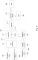
- Fig. 1 depicts a schematic diagram of a power converting system 100 according to one embodiment of the present disclosure.
- the power converting system 100 includes a power converting device 110, a protection device 120, and a charging device 130.
- the power converting device 110 is electrically connected to the protection device 120 and the charging device 130.
- the power converting device 110 includes multiple input/output ports. Two input/output ports of the power converting device 110 are electrically connected to a first power source 200 and a second power source 300. Besides, another input/output port of the power converting device 110 is electrically connected to the protection device 120, and the power converting device 110 is electrically connected to a grid 400 and a load 500 through the protection device 120. In addition, still another input/output port of the power converting device 110 is electrically connected to the charging device 130, and the power converting device 110 is electrically connected to a movable energy storage device 600 through the charging device 130. In some embodiments, the input/output port can include plural input/output terminals.
- the first power source 200 can be a photovoltaics panel. Therefore, the first power source 200 is configured to convert solar energy into electrical energy, and provide the electrical energy to the power converting device 110.
- the second power source 300 can be energy storage battery. Therefore, the second power source 300 is configured to store electrical energy provided by the power converting device 110, and provide electrical energy to the power converting device 110 through the second power source 300 if necessary.
- the second power source may be a power load for receiving and storing electricity.
- the protection device 120 includes a switch 121, a transformer 123, and a safe guard 125.
- the switch 121 can be a contactor or a relay. Therefore, the switch 121 can be configured to control a switch state among the power converting device 110, the grid 400, and the load 500.
- the transformer 123 can be an isolation transformer or an auto transformer, so as to perform a voltage-typed conversion.
- the safe guard 125 can be an overcurrent protection device or an electrical leakage protection device.
- the charging device 130 can be a charging gun, and the movable energy storage device 600 can be an electric vehicle. Therefore, the movable energy storage device 600 can be charged or discharged through the charging device 130.
- the movable energy storage device 600 includes a second converter 610 and a third power source 620.
- the third power source 620 can be an energy storage battery.
- the charging device 130 provides electricity to the second converter 610, and the second converter 610 converts electricity and stores it in the third power source 620.
- the third power source may be a power load for receiving and storing electricity.
- the power converting device 110 includes a first converter 111, a controller 113, a sensor 115, and a protector 117.
- the first converter 111 is electrically connected to the controller 113, the sensor 115, and the protector 117.
- the controller 113 is electrically connected to the sensor 115 and the protector 117.
- the first converter 111 includes multiple input/output ports.
- the first converter 111 can be configured to perform a DC/DC conversion, a DC/AC conversion, or an AC/DC conversion.
- the controller 113 is configured to control the whole system.
- the controller 113 can communication with the charging device 130 for controlling the movable energy storage device 600 to charge or discharge, or perform a protection function.
- the sensor 115 can be a current sampler, a voltage sampler, or a combination of the current sampler and the voltage sampler. The sensor 115 can detect the current, the voltage, and the power signal of the movable energy storage device 600, and provide the signals detected to the controller 113 for calculating the power of the movable energy storage device 600.
- the sensor 115 can be also configured to detect whether it is in an island state.
- the protector 117 can be a breaker, and can be configured to perform an overcurrent protection and an electrical leakage protection.
- the protector 117 can be used as equipment for activating the protection of the system. For example, when the sensor 115 detects the island state, the protector 117 will be activated to turn off a connection between the power converting system 100 and the grid 400.
- the power converting system 100 of the present disclosure assembles input/output ports of the first converter 111 and the charging device 130 together. Therefore, house hold power distribution capacity does not have to be extended, such that the installation cost and the maintenance cost can be reduced. In addition, since multiple input/output ports are assembled, the volume and the weight can be decreased so as to achieve better thermal management, simpler connection, and so on. Besides, the power converting system 100 of the present disclosure includes the sensor 115 to detect the input/output of the charging device 130, so as to satisfy requirements of the grid 400 to electricity consumption, electricity generation, and support.
- the power converting device 110 is a multi-port converting controller.
- the power converting device 110 is a four port converting controller.
- a port is connected to the first power source 200
- a port is connected to the second power source 300
- a port is connected to the charging device 130
- a port is connected to the protection device 120.
- the above-mentioned ports can be disposed in the power converting device 110 according to the application and the real system construction.
- the power converting device 110 can be used to power convert, control direction of the power flow, communicate with the inner system, communicate with the outer system, protect the system, and power manage.
- the controller 113 is a controlling and communicating core of the whole power converting system 100, which is used to implement a power conversion control, a communication with the inner system, a communication with the outer system, and a power management.
- the power conversion control can obtain the voltage and the current of the first power source 200 (e.g., photovoltaics panel) to calculate the power variation and the voltage variation so as to achieve the Maximum Power Point Tracking (MPPT) of the port of the first power source 200.
- MPPT Maximum Power Point Tracking
- the power conversion control can obtain the voltage and the current of the first power source 200 (e.g., photovoltaics panel) to calculate the power variation and the voltage variation so as to control active power and reactive power of the alternative current to achieve the power factor control and the frequency control.
- the controller 113 can communicate with the charging device 130 and the movable energy storage device 600 for determining whether the movable energy storage device 600 (e.g., electric vehicle) operates at a charge mode or a discharge mode.
- the controller 113 can obtain the sampling signal of the sensor 115, and calculate the power of the movable energy storage device 600.
- the controller 13 can communicate with the protection device 120, and control the power converting device 110 to switch between on-grid work mode and off-grid work mode.
- the controller 113 can be connected to Can through a router to achieve remote data feedback, monitor, and software update. Those functions can be achieved by one or multiple controllers.
- the charging device 130 includes a power converter, a controller, a relay or a contractor, a detector and a communicator.
- the charging device 130 can be an AC charger-typed connector.
- the power converter is a power converting portion to achieve DC/DC conversion function, for example, an auxiliary power.
- the power converter can be a power converting portion to achieve DC/AC conversion function, for example, the second converter 610 can be disposed in the charging device 130.
- the controller can control the power converter, and the communicator can perform a communication between the movable energy storage device 600 and the controller 113.
- the relay or a contactor can connect or cut off a connection between the power converting device 110 and the movable energy storage device 600.
- the detector is used to detect related signals of the charging device 130, and the related signals includes a voltage signal, a current signal, a power signal, and a temperature signal.
- the power converting system 100 of the present disclosure can provide the best power management in any state.
- the power converting system 100 of the present disclosure can select at least one power source of the first power source, the second power source, the third power source and the grid to provide electricity to the load according to multiple preset modes.
- the above-mentioned power management will be described in detail in the embodiments of Fig. 3 to Fig. 6 .
- Fig. 3 depicts a detailed schematic diagram of operating a power converting system 100 according to one embodiment of the present disclosure.
- the power converting system 100 works in a first mode.
- the first mode is that the power converting system 100 works during daytime, and the grid 400 can provide electricity. That is to say, the power converting system 100 is in an on-grid work mode and the power of the first power source 200 (e.g., photovoltaics panel) is higher.
- the power converting device 110 controls the first power source 200 to charge the second power source 300 (e.g., energy storage battery) and the third power source 620 (e.g., energy storage battery), and provide electricity to the load 500. If there is still additional electricity, it can be provided to the grid 400. If the need of the load 500 cannot be satisfied, the grid 400 can provide electricity to the load 500.
- the second power source 300 e.g., energy storage battery
- the third power source 620 e.g., energy storage battery
- the power converting device 110 will limit the output power of the first power source 200 (e.g., photovoltaics panel).
- Fig. 4 depicts a detailed schematic diagram of operating a power converting system 100 according to one embodiment of the present disclosure.
- the power converting system 100 works in a second mode.
- the second mode is that the power converting system 100 works at night, and the grid 400 can provide electricity. That is to say, the power converting system 100 is in an on-grid work mode and the first power source 200 (e.g., photovoltaics panel) cannot generate electricity.
- the controller 113 collects voltage signals and current signals of all power ports of the power converting system 100 for obtaining related states, thereby adopting suitable electricity management.
- electricity stored in the second power source 300 e.g., energy storage battery
- the third power source 620 e.g., energy storage battery
- the grid 400 can provide electricity to the load 500.
- the second power source 300 e.g., energy storage battery
- the second power source 300 has the priority to provide electricity to the load 500, so as to make sure that the movable energy storage device 600 (e.g., electric vehicle) always has electricity for using. If the movable energy storage device 600 shall be used tomorrow and electricity of the movable energy storage device 600 is lacking, the movable energy storage device 600 can be charged by the grid 400 during off-peak time so as to achieve greater benefits.
- Fig. 5 depicts a detailed schematic diagram of operating a power converting system 100 according to one embodiment of the present disclosure.
- the grid 400 stops providing electricity, so the power converting system 100 works in an off-grid work mode.
- the controller 113 detects an island state through the sensor 115, and controls the protector 117 to turn off a connection between the power converting system 100 and the grid 400.
- the way to detect the island state can be active island detection or inactive island detection.
- the way to detect the island state can be performed through obtaining the voltage and the frequency of the grid 400.
- the protection device 120 can switch the power converting system 100 from an on-grid work mode to an off-grid work mode through the switch 121 in Fig. 2 .
- the switch between the on-grid work mode and the off-grid work mode not only can be performed by the power converting system 100 actively, but also can be performed manually.
- the power converting system 100 can continuously provide electricity to the load 500 for the need of emergency electricity and continuous electricity, for example, emergency lighting, refrigerator, and so on.
- the power converting system 100 works in a third mode.
- the third mode is that the power converting system 100 works at daytime and the grid 400 stops providing electricity. That is to say, the power converting system 100 is in an off-grid work mode and the power of the first power source 200 (e.g., photovoltaics panel) is high.
- the power converting device 110 controls the first power source 200 to provide electricity to the load 500. If there is still additional electricity, the second power source 300 (e.g., energy storage battery) and the third power source 620 (e.g., energy storage battery) can be charged selectivity.
- the second power source 300 e.g., energy storage battery
- the third power source 620 e.g., energy storage battery
- the power converting device 110 will limit the output power of the first power source 200. Besides, if the power of the first power source 200 is not enough to provide electricity to the load 500, the second power source 300 and/or the third power source 620 can be used to provide electricity to the load 500.
- Fig. 6 depicts a detailed schematic diagram of operating a power converting system 100 according to one embodiment of the present disclosure.
- the power converting system 100 works in a fourth mode.
- the fourth mode is that the power converting system 100 works at night, and the grid 400 stops providing electricity. That is to say, the power converting system 100 is in an off-grid work mode and the first power source 200 (e.g., photovoltaics panel) cannot generate electricity.
- the second power source 300 e.g., energy storage battery
- the third power source 620 e.g., energy storage battery
- the controller 113 will control the second power source 300 to provide electricity to the load 500 so as to ensure that the movable energy storage device 600 (e.g., electric vehicle) has electricity for usage at any time.
- Fig. 7 depicts a schematic diagram of a power converting system 100 according to one embodiment of the present disclosure.
- the sensor 115 of the power converting system 100 in Fig. 7 is not electrically connected to the charging device 130 in a direct way.
- the sensor 115 obtains signals at a public point of the first converter 111 and the charging device 130 indirectly, and the related information of the charging device 130 can be obtained through calculation.
- Fig. 8 depicts a schematic diagram of the first converter 111 of the power converting device 110 of the power converting system 100 shown in Fig. 7 according to one embodiment of the present disclosure.
- the first converter 111 of the power converting device 110 includes a first sub-converter 112, a second sub-converter 114, a DC bus 116, and a third sub-converter 118.
- the first sub-converter 112 is coupled to the first power source 200 and the DC bus 116, and configured to receive and adjust a power provided by the first power source 200.
- the first sub-converter 112 can be a unidirectional DC-DC converter, such as a boost converter, and the first power source 200 can be a DC power source.
- the unidirectional DC-DC converter 112 is configured to receive the power provided by the DC power source 200 and convert a port voltage of the DC power source 200 to fit the voltage of the DC bus 116.
- the second sub-converter 114 is coupled to the second power source 300 and the DC bus 116.
- the second sub-converter 114 is configured to receive and adjust a power provided by the second power source 300, or configured to charge the second power source 300.
- the second sub-converter 114 can be a bidirectional DC-DC converter, such as a Dual Active Bridge (DAB) series resonance converter, and the second power source 300 can be a DC power source.
- the bidirectional DC-DC converter 114 is configured to receive the power provided by the DC power source 300 and convert a port voltage of the DC power source 300 to fit the voltage of the DC bus 116, or configured to charge the DC power source 300.
- DAB Dual Active Bridge
- the third sub-converter 118 is coupled to the DC bus 116, and the third sub-converter 118 is coupled to the protection device 120 through the sensor 115 and the protector 117.
- the third sub-converter 118 can be a bidirectional DC-AC converter.
- the bidirectional DC-AC converter may be configured to receive the AC power from the grid 400 and convert the AC power into a DC power.
- the DC power obtained can be used to charge the second power source (e.g., high-voltage batteries) and/or the movable energy storage device (e.g., electric vehicle).
- the bidirectional DC-AC converter may be configured to receive the DC power from at least one DC power source and convert the DC power into a AC power.
- the AC power obtained can be provided to the grid 400 or the load 500, or be used to charge the movable energy storage device (e.g., electric vehicle).
- Fig. 9 depicts a schematic diagram of a power converting system 100 according to one embodiment of the present disclosure.
- the power converting device 110 of the power converting system 100 includes plural input/output ports.
- An input/output port of the power converting device 110 is electrically connected to the first power source 200
- an input/output port of the power converting device 110 is electrically connected to the second power source 300.
- another input/output port of the power converting device 110 is electrically connected to the protection device 120
- the power converting device 110 is electrically connected to the grid 400 and the load 500 through the protection device 120.
- still another input/output port of the power converting device 110 is electrically connected to the charging device 130, and the power converting device 110 is electrically connected to the movable energy storage device 600 through the charging device 130.
- the first power source 200 can be Photovoltaics (PV) device. Therefore, the first power source 200 can be configured to convert solar energy into electrical energy, and provide the electrical energy to the power converting device 110.
- the second power source 300 can be an energy storage battery. Therefore, the second power source 300 can be configured to store electrical energy provided by the power converting device 110, and provide electrical energy to the power converting device 110 when needed.
- the charging device 130 in Fig. 1 is coupled to the protector 117.
- the charging device 130 is coupled to an AC side of the power converting device 110, and is electrically connected to the protection device 120 through the protector 117, and further electrically connected to the grid 400 through the protection device 120.
- the charging device 130 in Fig. 9 is coupled to the DC bus 116 of the power converting device 110. Therefore, the third power 620 in Fig. 9 does not need the second converter 610 in Fig. 1 . Accordingly, the controller 113 of the power converting system 100 can detect current, voltage, and/or power in the DC bus 116 to control a state of the port connected to the charging device 130, thereby satisfying the requirements of the movable energy storage device 600.
- the charging device 130 includes a power converter, a controller, a relay or contactor, a detector, and a communicator.
- the charging device 130 can be a DC charging gun.
- the power converter is a part of the power conversion.
- the power converter can implement DC /DC conversion, for example supplying auxiliary power.
- the charging device is coupled to a grid through a distribution board.
- the charging device 130 is coupled to AC side or DC bus of the power converting system 110, and the charge equipment (for example, electric vehicle) does not need to use grid-connected capacity independently.
- the power converting system of the present disclosure can integrate solar energy, storage energy, and charge energy. When introducing the charging equipment, the solar energy and energy storage equipment will be considered, so as to enhance usage efficiency of renewable energy.
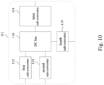
- Fig. 10 depicts a schematic diagram of the first converter 111 of the power converting device 110 of the power converting system 100 shown in Fig. 9 according to one embodiment of the present disclosure.
- the first converter 111 of the power converting device 110 incudes a first sub-converter 112, a second sub-converter 114, a DC bus 116, a third sub-converter 118, and a fourth sub-converter 119.
- the first converter 111 of the power converting device 110 in Fig. 10 further includes a fourth sub-converter 119.
- the fourth sub-converter 119 is coupled to the DC bus 116 and the charging device 130.
- the fourth sub-converter 119 receives a power provided by the third power source 620 through the charging device 130 and converts the power provided by the third power source 620 to fit the DC bus 116, or charges the third power source 620 through the charging device 130.
- the fourth sub-converter 119 can be a bidirectional DC-DC converter, such as a DAB series resonance converter, and the third power source 620 can be DC power source.
- the bidirectional DC-DC converter 119 is configured to receive the power provided by the DC power source 620, or configured to charge the DC power source 620. Therefore, the third power source 620 in Fig. 10 does not need the second converter 610 in Fig. 1 to transform DC electrical energy into AC electrical energy.
- Fig. 11 depicts a schematic diagram of the first converter 111 of the power converting device 110 of the power converting system 100 shown in Fig. 9 according to one embodiment of the present disclosure.
- the first converter 111 of the power converting device 110 in Fig. 11 further includes a sensor 121.
- the sensor 121 is coupled to the DC bus 116.
- the sensor 121 can be configured to at least detect the state of the DC bus 116.
- Fig. 12 depicts a schematic diagram of the first converter 111 of the power converting device 110 of the power converting system 100 shown in Fig. 9 according to one embodiment of the present disclosure. Compared with Fig. 10 , the power converting device 110 in Fig. 12 does not need the second sub-converter 114, and the power of the second power 300 can be transmitted to the DC bus 116 directly.
- Fig. 13 depicts a schematic diagram of the first converter 111 of the power converting device 110 of the power converting system 100 shown in Fig. 12 according to one embodiment of the present disclosure.
- the first sub-converter 112 is coupled to the first power source 200.
- the DC bus 116 can be directly coupled to the second power source 300.
- the third sub-converter 118 is coupled to the DC bus 116, and the third sub-converter 118 is coupled to the protection device 120 through the sensor 115 and the protector 117.
- the fourth sub-converter 119 is coupled to the DC bus 116 and the charging device 130.
- the controller 113 of the first converter 111 of the power converting device 110 can be implemented by plural controllers, for example, controllers 1111, 1112, 1113.
- the controller 1111 can be configured to collect signals of nodes N1, N2, N3 for controlling the first sub-converter 112 and the third sub-converter 118.
- the controller 1112 can be configured to collect signals of nodes N4, N5 for controlling the fourth sub-converter 119.
- the controller 1113 is mainly configured to communicate with other devices. For example, the controller 1113 collects signals of the second power source 300 and the third power source 620, and communicates with the controller 1111 and the controller 1112.
- the first converter 111 of the power converting device 110 sets the sensor at the node N2 or the node N5.
- the sensor at the node N2 or the node N5 is configured to detect signals of the DC bus 116, and transmit the signals detected to the controllers 1111, 1112.
- the third sub-converter 118 and the fourth sub-converter 119 can share the sensor so as to reduce the cost of the hardware.
- the first converter 111 of the power converting device 110 sets the sensors 122, 123 at the node N2 and the node N5, and each of the sensors 122, 123 is configured to detect the signals of the DC bus 116.
- the sensor 122 at the node N2 only needs to transmit the signals detected to the controller 1111 nearby, and the sensor 123 at the node N5 only needs to transmit the signals detected to the controller 1112 nearby, thereby avoiding interference during the transmitting process.
- Fig. 14 depicts a schematic diagram of the power converting device 110 of the power converting system 100 shown in Fig. 9 according to one embodiment of the present disclosure.
- the power converting system includes a first sub-converter 112, a DC bus 116, a third sub-converter 118, and a fourth sub-converter 119.
- the first power source 200 can be Photovoltaics (PV) panel
- the second power source 300 can be energy storage batteries (BAT)
- the grid 400 can be single-phase AC grid.
- the charging device 130 can be a connector coupled to the movable energy storage device (such as electric vehicle) and the fourth sub-converter 119.
- the first sub-converter 112 can be a unidirectional DC-DC converter, for example, a boost converter.
- the DC bus 116 can be bus capacitors C bus .
- the third sub-converter 118 can be a bidirectional DC-AC inverter.
- the fourth sub-converter 119 can be a bidirectional DC-DC converter, for example, a Dual-Active Bridge Series Resonant Converter (DAB-SRC).
- DAB-SRC Dual-Active Bridge Series Resonant Converter
- the power converting system of the present disclosure can perform a compensation to the output of the charging device according to the signals detected. Besides, the controllers of the power converting device controls the multiple converters according to the signals detected so as to achieve the best power management. In addition, since input/output ports of the power converting device and the charging device are assembled together, volume and weight of the power converting system is reduced so as to achieve better thermal management, simpler connection, and so on.
Landscapes
- Engineering & Computer Science (AREA)
- Power Engineering (AREA)
- Transportation (AREA)
- Mechanical Engineering (AREA)
- Charge And Discharge Circuits For Batteries Or The Like (AREA)
Abstract
Description
- The present disclosure relates to a converting device. More particularly, the present disclosure relates to a power converting system.
- Solar battery charger system nowadays is usually constructed by multiple independent sub-systems. Photovoltaic (PV) energy storage system usually includes PV inverter and battery inverter to achieve energy conversion between new energy generation and energy storage through AC couple. Or Photovoltaic (PV) energy storage system achieves energy conversion between new energy generation and energy storage through DC couple. Electric vehicle (EV) charger is also connected to AC grid directly.
- The Photovoltaic (PV) energy storage system and the electric vehicle charger are all independent devices. Since communication ports of each of the independent devices do not have a uniform standards and a uniform communication protocol, it is hard to communicate among the devices, such that it is not easy to achieve an electricity management among the whole system. In addition, each independent system needs independent grid-connected capacity, so the capacity of the AC ports will be not enough; and the installation cost and the maintenance cost are high.
- One aspect of the present disclosure is to provide a power converting system. The power converting system includes a power converting device, a protection device, and a charging device. The power converting device is coupled to a first power source and a second power source. The protection device is coupled to the power converting device, a load, and a grid, and configured to switch electrical connections among the power converting device, the load, and the grid. The charging device is coupled to the power converting device and a third power source. The power converting device charges the third power source through the charging device, or receives electricity of the third power source through the charging device. Select at least one power source of the first power source, the second power source, the third power source and the grid to provide electricity to the load according to multiple preset modes.
- It is to be understood that both the foregoing general description and the following detailed description are by examples, and are intended to provide further explanation of the disclosure as claimed.
- The accompanying drawings are included to provide a further understanding of the present disclosure, and are incorporated in and constitute a part of this specification. The drawings illustrate embodiments of the present disclosure and, together with the description, serve to explain the principles of the present disclosure. In the drawings,
-
Fig. 1 depicts a schematic diagram of a power converting system according to one embodiment of the present disclosure; -
Fig. 2 depicts a schematic diagram of a protecting device of the power converting system shown inFig. 1 according to one embodiment of the present disclosure; -
Fig. 3 depicts a schematic diagram of operating a power converting system according to one embodiment of the present disclosure; -
Fig. 4 depicts a schematic diagram of operating a power converting system according to one embodiment of the present disclosure; -
Fig. 5 depicts a schematic diagram of operating a power converting system according to one embodiment of the present disclosure; -
Fig. 6 depicts a schematic diagram of operating a power converting system according to one embodiment of the present disclosure; -
Fig. 7 depicts a schematic diagram of a power converting system according to one embodiment of the present disclosure; -
Fig. 8 depicts a schematic diagram of a power converting device of the power converting system shown inFig. 7 according to one embodiment of the present disclosure; -
Fig. 9 depicts a schematic diagram of a power converting system according to one embodiment of the present disclosure; -
Fig. 10 depicts a schematic diagram of a power converting device of the power converting system shown inFig. 9 according to one embodiment of the present disclosure; -
Fig. 11 depicts a schematic diagram of a power converting device of the power converting system shown inFig. 9 according to one embodiment of the present disclosure; -
Fig. 12 depicts a schematic diagram of a power converting device of the power converting system shown inFig. 9 according to one embodiment of the present disclosure; -
Fig. 13 depicts a schematic diagram of a power converting device of the power converting system shown inFig. 12 according to one embodiment of the present disclosure; and -
Fig. 14 depicts a schematic diagram of a power converting device of the power converting system shown inFig. 9 according to one embodiment of the present disclosure. - According to the usual mode of operation, various features and elements in the figures have not been drawn to scale, which are drawn to the best way to present specific features and elements related to the present disclosure. In addition, among the different figures, the same or similar element symbols refer to similar elements/components.
- To make the contents of the present disclosure more thorough and complete, the following illustrative description is given with regard to the implementation aspects and embodiments of the present disclosure, which is not intended to limit the scope of the present disclosure. The features of the embodiments and the steps of the method and their sequences that constitute and implement the embodiments are described. However, other embodiments may be used to achieve the same or equivalent functions and step sequences.
- Unless otherwise defined herein, scientific and technical terminologies employed in the present disclosure shall have the meanings that are commonly understood and used by one of ordinary skill in the art. Unless otherwise required by context, it will be understood that singular terms shall include plural forms of the same and plural terms shall include the singular. Specifically, as used herein and in the claims, the singular forms "a" and "an" include the plural reference unless the context clearly indicates otherwise.
-
Fig. 1 depicts a schematic diagram of apower converting system 100 according to one embodiment of the present disclosure. As shown in the figure, thepower converting system 100 includes apower converting device 110, aprotection device 120, and acharging device 130. Thepower converting device 110 is electrically connected to theprotection device 120 and thecharging device 130. - The
power converting device 110 includes multiple input/output ports. Two input/output ports of thepower converting device 110 are electrically connected to afirst power source 200 and asecond power source 300. Besides, another input/output port of thepower converting device 110 is electrically connected to theprotection device 120, and thepower converting device 110 is electrically connected to agrid 400 and aload 500 through theprotection device 120. In addition, still another input/output port of thepower converting device 110 is electrically connected to thecharging device 130, and thepower converting device 110 is electrically connected to a movableenergy storage device 600 through thecharging device 130. In some embodiments, the input/output port can include plural input/output terminals. - For example, the
first power source 200 can be a photovoltaics panel. Therefore, thefirst power source 200 is configured to convert solar energy into electrical energy, and provide the electrical energy to thepower converting device 110. Thesecond power source 300 can be energy storage battery. Therefore, thesecond power source 300 is configured to store electrical energy provided by thepower converting device 110, and provide electrical energy to thepower converting device 110 through thesecond power source 300 if necessary. In some operation modes, the second power source may be a power load for receiving and storing electricity. - As shown in
Fig. 2 , theprotection device 120 includes aswitch 121, atransformer 123, and asafe guard 125. Theswitch 121 can be a contactor or a relay. Therefore, theswitch 121 can be configured to control a switch state among thepower converting device 110, thegrid 400, and theload 500. Thetransformer 123 can be an isolation transformer or an auto transformer, so as to perform a voltage-typed conversion. Thesafe guard 125 can be an overcurrent protection device or an electrical leakage protection device. - As shown in
Fig. 1 , the chargingdevice 130 can be a charging gun, and the movableenergy storage device 600 can be an electric vehicle. Therefore, the movableenergy storage device 600 can be charged or discharged through thecharging device 130. Specifically, the movableenergy storage device 600 includes asecond converter 610 and athird power source 620. Thethird power source 620 can be an energy storage battery. The chargingdevice 130 provides electricity to thesecond converter 610, and thesecond converter 610 converts electricity and stores it in thethird power source 620. In some operation modes, the third power source may be a power load for receiving and storing electricity. - In one embodiment, the
power converting device 110 includes afirst converter 111, acontroller 113, asensor 115, and aprotector 117. Thefirst converter 111 is electrically connected to thecontroller 113, thesensor 115, and theprotector 117. Thecontroller 113 is electrically connected to thesensor 115 and theprotector 117. - For example, the
first converter 111 includes multiple input/output ports. Thefirst converter 111 can be configured to perform a DC/DC conversion, a DC/AC conversion, or an AC/DC conversion. Thecontroller 113 is configured to control the whole system. For instance, thecontroller 113 can communication with the chargingdevice 130 for controlling the movableenergy storage device 600 to charge or discharge, or perform a protection function. Thesensor 115 can be a current sampler, a voltage sampler, or a combination of the current sampler and the voltage sampler. Thesensor 115 can detect the current, the voltage, and the power signal of the movableenergy storage device 600, and provide the signals detected to thecontroller 113 for calculating the power of the movableenergy storage device 600. Besides, thesensor 115 can be also configured to detect whether it is in an island state. Theprotector 117 can be a breaker, and can be configured to perform an overcurrent protection and an electrical leakage protection. Theprotector 117 can be used as equipment for activating the protection of the system. For example, when thesensor 115 detects the island state, theprotector 117 will be activated to turn off a connection between thepower converting system 100 and thegrid 400. - As described above, the
power converting system 100 of the present disclosure assembles input/output ports of thefirst converter 111 and thecharging device 130 together. Therefore, house hold power distribution capacity does not have to be extended, such that the installation cost and the maintenance cost can be reduced. In addition, since multiple input/output ports are assembled, the volume and the weight can be decreased so as to achieve better thermal management, simpler connection, and so on. Besides, thepower converting system 100 of the present disclosure includes thesensor 115 to detect the input/output of thecharging device 130, so as to satisfy requirements of thegrid 400 to electricity consumption, electricity generation, and support. - In one embodiment, the
power converting device 110 is a multi-port converting controller. For example, thepower converting device 110 is a four port converting controller. A port is connected to thefirst power source 200, a port is connected to thesecond power source 300, a port is connected to thecharging device 130, and a port is connected to theprotection device 120. The above-mentioned ports can be disposed in thepower converting device 110 according to the application and the real system construction. Thepower converting device 110 can be used to power convert, control direction of the power flow, communicate with the inner system, communicate with the outer system, protect the system, and power manage. - In one embodiment, the
controller 113 is a controlling and communicating core of the wholepower converting system 100, which is used to implement a power conversion control, a communication with the inner system, a communication with the outer system, and a power management. The power conversion control can obtain the voltage and the current of the first power source 200 (e.g., photovoltaics panel) to calculate the power variation and the voltage variation so as to achieve the Maximum Power Point Tracking (MPPT) of the port of thefirst power source 200. Simultaneously, the power conversion control can obtain the voltage and the current of the first power source 200 (e.g., photovoltaics panel) to calculate the power variation and the voltage variation so as to control active power and reactive power of the alternative current to achieve the power factor control and the frequency control. Thecontroller 113 can communicate with the chargingdevice 130 and the movableenergy storage device 600 for determining whether the movable energy storage device 600 (e.g., electric vehicle) operates at a charge mode or a discharge mode. Thecontroller 113 can obtain the sampling signal of thesensor 115, and calculate the power of the movableenergy storage device 600. The controller 13 can communicate with theprotection device 120, and control thepower converting device 110 to switch between on-grid work mode and off-grid work mode. Thecontroller 113 can be connected to Could through a router to achieve remote data feedback, monitor, and software update. Those functions can be achieved by one or multiple controllers. - In one embodiment, the charging
device 130 includes a power converter, a controller, a relay or a contractor, a detector and a communicator. The chargingdevice 130 can be an AC charger-typed connector. The power converter is a power converting portion to achieve DC/DC conversion function, for example, an auxiliary power. The power converter can be a power converting portion to achieve DC/AC conversion function, for example, thesecond converter 610 can be disposed in thecharging device 130. The controller can control the power converter, and the communicator can perform a communication between the movableenergy storage device 600 and thecontroller 113. The relay or a contactor can connect or cut off a connection between thepower converting device 110 and the movableenergy storage device 600. The detector is used to detect related signals of thecharging device 130, and the related signals includes a voltage signal, a current signal, a power signal, and a temperature signal. - The
power converting system 100 of the present disclosure can provide the best power management in any state. Thepower converting system 100 of the present disclosure can select at least one power source of the first power source, the second power source, the third power source and the grid to provide electricity to the load according to multiple preset modes. The above-mentioned power management will be described in detail in the embodiments ofFig. 3 to Fig. 6 . -
Fig. 3 depicts a detailed schematic diagram of operating apower converting system 100 according to one embodiment of the present disclosure. In this embodiment, thepower converting system 100 works in a first mode. The first mode is that thepower converting system 100 works during daytime, and thegrid 400 can provide electricity. That is to say, thepower converting system 100 is in an on-grid work mode and the power of the first power source 200 (e.g., photovoltaics panel) is higher. Thepower converting device 110 controls thefirst power source 200 to charge the second power source 300 (e.g., energy storage battery) and the third power source 620 (e.g., energy storage battery), and provide electricity to theload 500. If there is still additional electricity, it can be provided to thegrid 400. If the need of theload 500 cannot be satisfied, thegrid 400 can provide electricity to theload 500. - If additional electricity cannot be used by the
load 500, cannot be stored in the second power source 300 (e.g., energy storage battery) and the third power source 620 (e.g., energy storage battery), and cannot be provided to thegrid 400, thepower converting device 110 will limit the output power of the first power source 200 (e.g., photovoltaics panel). -
Fig. 4 depicts a detailed schematic diagram of operating apower converting system 100 according to one embodiment of the present disclosure. In this embodiment, thepower converting system 100 works in a second mode. The second mode is that thepower converting system 100 works at night, and thegrid 400 can provide electricity. That is to say, thepower converting system 100 is in an on-grid work mode and the first power source 200 (e.g., photovoltaics panel) cannot generate electricity. Thecontroller 113 collects voltage signals and current signals of all power ports of thepower converting system 100 for obtaining related states, thereby adopting suitable electricity management. For example, electricity stored in the second power source 300 (e.g., energy storage battery) and the third power source 620 (e.g., energy storage battery) can be provided to theload 500. If the need of theload 500 cannot be satisfied, thegrid 400 can provide electricity to theload 500. - In addition, if the power need by the
load 500 is not high, the second power source 300 (e.g., energy storage battery) has the priority to provide electricity to theload 500, so as to make sure that the movable energy storage device 600 (e.g., electric vehicle) always has electricity for using. If the movableenergy storage device 600 shall be used tomorrow and electricity of the movableenergy storage device 600 is lacking, the movableenergy storage device 600 can be charged by thegrid 400 during off-peak time so as to achieve greater benefits. -
Fig. 5 depicts a detailed schematic diagram of operating apower converting system 100 according to one embodiment of the present disclosure. In this embodiment, thegrid 400 stops providing electricity, so thepower converting system 100 works in an off-grid work mode. At this time, thecontroller 113 detects an island state through thesensor 115, and controls theprotector 117 to turn off a connection between thepower converting system 100 and thegrid 400. The way to detect the island state can be active island detection or inactive island detection. In addition, the way to detect the island state can be performed through obtaining the voltage and the frequency of thegrid 400. - Besides, the
protection device 120 can switch thepower converting system 100 from an on-grid work mode to an off-grid work mode through theswitch 121 inFig. 2 . The switch between the on-grid work mode and the off-grid work mode not only can be performed by thepower converting system 100 actively, but also can be performed manually. After accessing the off-grid work mode, thepower converting system 100 can continuously provide electricity to theload 500 for the need of emergency electricity and continuous electricity, for example, emergency lighting, refrigerator, and so on. - In some embodiments, the
power converting system 100 works in a third mode. The third mode is that thepower converting system 100 works at daytime and thegrid 400 stops providing electricity. That is to say, thepower converting system 100 is in an off-grid work mode and the power of the first power source 200 (e.g., photovoltaics panel) is high. Thepower converting device 110 controls thefirst power source 200 to provide electricity to theload 500. If there is still additional electricity, the second power source 300 (e.g., energy storage battery) and the third power source 620 (e.g., energy storage battery) can be charged selectivity. If additional electricity is not used by theload 500, and cannot be stored in thesecond power source 300 and thethird power source 620, thepower converting device 110 will limit the output power of thefirst power source 200. Besides, if the power of thefirst power source 200 is not enough to provide electricity to theload 500, thesecond power source 300 and/or thethird power source 620 can be used to provide electricity to theload 500. -
Fig. 6 depicts a detailed schematic diagram of operating apower converting system 100 according to one embodiment of the present disclosure. In this embodiment, thepower converting system 100 works in a fourth mode. The fourth mode is that thepower converting system 100 works at night, and thegrid 400 stops providing electricity. That is to say, thepower converting system 100 is in an off-grid work mode and the first power source 200 (e.g., photovoltaics panel) cannot generate electricity. The second power source 300 (e.g., energy storage battery) and/or the third power source 620 (e.g., energy storage battery) can provide electricity to theload 500. If the need for the power of theload 500 is not high, thecontroller 113 will control thesecond power source 300 to provide electricity to theload 500 so as to ensure that the movable energy storage device 600 (e.g., electric vehicle) has electricity for usage at any time. -
Fig. 7 depicts a schematic diagram of apower converting system 100 according to one embodiment of the present disclosure. Compared to thepower converting system 100 inFig. 1 , thesensor 115 of thepower converting system 100 inFig. 7 is not electrically connected to thecharging device 130 in a direct way. At this time, thesensor 115 obtains signals at a public point of thefirst converter 111 and thecharging device 130 indirectly, and the related information of thecharging device 130 can be obtained through calculation. -
Fig. 8 depicts a schematic diagram of thefirst converter 111 of thepower converting device 110 of thepower converting system 100 shown inFig. 7 according to one embodiment of the present disclosure. As shown in the figure, thefirst converter 111 of thepower converting device 110 includes afirst sub-converter 112, asecond sub-converter 114, aDC bus 116, and athird sub-converter 118. - In one embodiment, the
first sub-converter 112 is coupled to thefirst power source 200 and theDC bus 116, and configured to receive and adjust a power provided by thefirst power source 200. For example, thefirst sub-converter 112 can be a unidirectional DC-DC converter, such as a boost converter, and thefirst power source 200 can be a DC power source. The unidirectional DC-DC converter 112 is configured to receive the power provided by theDC power source 200 and convert a port voltage of theDC power source 200 to fit the voltage of theDC bus 116. - In one embodiment, the
second sub-converter 114 is coupled to thesecond power source 300 and theDC bus 116. Thesecond sub-converter 114 is configured to receive and adjust a power provided by thesecond power source 300, or configured to charge thesecond power source 300. For example, thesecond sub-converter 114 can be a bidirectional DC-DC converter, such as a Dual Active Bridge (DAB) series resonance converter, and thesecond power source 300 can be a DC power source. The bidirectional DC-DC converter 114 is configured to receive the power provided by theDC power source 300 and convert a port voltage of theDC power source 300 to fit the voltage of theDC bus 116, or configured to charge theDC power source 300. Thethird sub-converter 118 is coupled to theDC bus 116, and thethird sub-converter 118 is coupled to theprotection device 120 through thesensor 115 and theprotector 117. For example, thethird sub-converter 118 can be a bidirectional DC-AC converter. The bidirectional DC-AC converter may be configured to receive the AC power from thegrid 400 and convert the AC power into a DC power. The DC power obtained can be used to charge the second power source (e.g., high-voltage batteries) and/or the movable energy storage device (e.g., electric vehicle). The bidirectional DC-AC converter may be configured to receive the DC power from at least one DC power source and convert the DC power into a AC power. The AC power obtained can be provided to thegrid 400 or theload 500, or be used to charge the movable energy storage device (e.g., electric vehicle). -
Fig. 9 depicts a schematic diagram of apower converting system 100 according to one embodiment of the present disclosure. As shown inFig. 9 , thepower converting device 110 of thepower converting system 100 includes plural input/output ports. An input/output port of thepower converting device 110 is electrically connected to thefirst power source 200, an input/output port of thepower converting device 110 is electrically connected to thesecond power source 300. In addition, another input/output port of thepower converting device 110 is electrically connected to theprotection device 120, and thepower converting device 110 is electrically connected to thegrid 400 and theload 500 through theprotection device 120. Besides, still another input/output port of thepower converting device 110 is electrically connected to thecharging device 130, and thepower converting device 110 is electrically connected to the movableenergy storage device 600 through thecharging device 130. - For example, the
first power source 200 can be Photovoltaics (PV) device. Therefore, thefirst power source 200 can be configured to convert solar energy into electrical energy, and provide the electrical energy to thepower converting device 110. Thesecond power source 300 can be an energy storage battery. Therefore, thesecond power source 300 can be configured to store electrical energy provided by thepower converting device 110, and provide electrical energy to thepower converting device 110 when needed. - The charging
device 130 inFig. 1 is coupled to theprotector 117. For example, in one embodiment, the chargingdevice 130 is coupled to an AC side of thepower converting device 110, and is electrically connected to theprotection device 120 through theprotector 117, and further electrically connected to thegrid 400 through theprotection device 120. The chargingdevice 130 inFig. 9 is coupled to theDC bus 116 of thepower converting device 110. Therefore, thethird power 620 inFig. 9 does not need thesecond converter 610 inFig. 1 . Accordingly, thecontroller 113 of thepower converting system 100 can detect current, voltage, and/or power in theDC bus 116 to control a state of the port connected to thecharging device 130, thereby satisfying the requirements of the movableenergy storage device 600. In this embodiment, the chargingdevice 130 includes a power converter, a controller, a relay or contactor, a detector, and a communicator. The chargingdevice 130 can be a DC charging gun. The power converter is a part of the power conversion. The power converter can implement DC /DC conversion, for example supplying auxiliary power. - In the prior art, the charging device is coupled to a grid through a distribution board. In the present disclosure, the charging
device 130 is coupled to AC side or DC bus of thepower converting system 110, and the charge equipment (for example, electric vehicle) does not need to use grid-connected capacity independently. The power converting system of the present disclosure can integrate solar energy, storage energy, and charge energy. When introducing the charging equipment, the solar energy and energy storage equipment will be considered, so as to enhance usage efficiency of renewable energy. -
Fig. 10 depicts a schematic diagram of thefirst converter 111 of thepower converting device 110 of thepower converting system 100 shown inFig. 9 according to one embodiment of the present disclosure. As shown inFig. 10 , thefirst converter 111 of thepower converting device 110 incudes afirst sub-converter 112, asecond sub-converter 114, aDC bus 116, athird sub-converter 118, and afourth sub-converter 119. - Compared with
Fig. 8 , thefirst converter 111 of thepower converting device 110 inFig. 10 further includes afourth sub-converter 119. Thefourth sub-converter 119 is coupled to theDC bus 116 and thecharging device 130. Thefourth sub-converter 119 receives a power provided by thethird power source 620 through thecharging device 130 and converts the power provided by thethird power source 620 to fit theDC bus 116, or charges thethird power source 620 through thecharging device 130. For example, thefourth sub-converter 119 can be a bidirectional DC-DC converter, such as a DAB series resonance converter, and thethird power source 620 can be DC power source. The bidirectional DC-DC converter 119 is configured to receive the power provided by theDC power source 620, or configured to charge theDC power source 620. Therefore, thethird power source 620 inFig. 10 does not need thesecond converter 610 inFig. 1 to transform DC electrical energy into AC electrical energy. -
Fig. 11 depicts a schematic diagram of thefirst converter 111 of thepower converting device 110 of thepower converting system 100 shown inFig. 9 according to one embodiment of the present disclosure. Compared withFig. 10 , thefirst converter 111 of thepower converting device 110 inFig. 11 further includes asensor 121. Thesensor 121 is coupled to theDC bus 116. Thesensor 121 can be configured to at least detect the state of theDC bus 116. -
Fig. 12 depicts a schematic diagram of thefirst converter 111 of thepower converting device 110 of thepower converting system 100 shown inFig. 9 according to one embodiment of the present disclosure. Compared withFig. 10 , thepower converting device 110 inFig. 12 does not need thesecond sub-converter 114, and the power of thesecond power 300 can be transmitted to theDC bus 116 directly. -
Fig. 13 depicts a schematic diagram of thefirst converter 111 of thepower converting device 110 of thepower converting system 100 shown inFig. 12 according to one embodiment of the present disclosure. As shown inFig. 13 , thefirst sub-converter 112 is coupled to thefirst power source 200. TheDC bus 116 can be directly coupled to thesecond power source 300. Thethird sub-converter 118 is coupled to theDC bus 116, and thethird sub-converter 118 is coupled to theprotection device 120 through thesensor 115 and theprotector 117. Thefourth sub-converter 119 is coupled to theDC bus 116 and thecharging device 130. - In one embodiment, the
controller 113 of thefirst converter 111 of thepower converting device 110 can be implemented by plural controllers, for example,controllers controller 1111 can be configured to collect signals of nodes N1, N2, N3 for controlling thefirst sub-converter 112 and thethird sub-converter 118. Thecontroller 1112 can be configured to collect signals of nodes N4, N5 for controlling thefourth sub-converter 119. Thecontroller 1113 is mainly configured to communicate with other devices. For example, thecontroller 1113 collects signals of thesecond power source 300 and thethird power source 620, and communicates with thecontroller 1111 and thecontroller 1112. - In one embodiment, the
first converter 111 of thepower converting device 110 sets the sensor at the node N2 or the node N5. The sensor at the node N2 or the node N5 is configured to detect signals of theDC bus 116, and transmit the signals detected to thecontrollers third sub-converter 118 and thefourth sub-converter 119 can share the sensor so as to reduce the cost of the hardware. - When the sensor is at the node N2, the signals detected by the sensor are transmitted to the
controller 1112 through a long distance, and as a result, the signals are interfered during the transmitting process. When the sensor is at the node N5, the signals detected by the sensor are transmitted to thecontroller 1111 through a long distance, and as a result, the signals are interfered during the transmitting process. In another embodiment, thefirst converter 111 of thepower converting device 110 sets thesensors sensors DC bus 116. Thesensor 122 at the node N2 only needs to transmit the signals detected to thecontroller 1111 nearby, and thesensor 123 at the node N5 only needs to transmit the signals detected to thecontroller 1112 nearby, thereby avoiding interference during the transmitting process. -
Fig. 14 depicts a schematic diagram of thepower converting device 110 of thepower converting system 100 shown inFig. 9 according to one embodiment of the present disclosure. As shown inFig. 14 , the power converting system includes afirst sub-converter 112, aDC bus 116, athird sub-converter 118, and afourth sub-converter 119. Thefirst power source 200 can be Photovoltaics (PV) panel, thesecond power source 300 can be energy storage batteries (BAT), and thegrid 400 can be single-phase AC grid. The chargingdevice 130 can be a connector coupled to the movable energy storage device (such as electric vehicle) and thefourth sub-converter 119. Thefirst sub-converter 112 can be a unidirectional DC-DC converter, for example, a boost converter. TheDC bus 116 can be bus capacitors Cbus. Thethird sub-converter 118 can be a bidirectional DC-AC inverter. Thefourth sub-converter 119 can be a bidirectional DC-DC converter, for example, a Dual-Active Bridge Series Resonant Converter (DAB-SRC). - The power converting system of the present disclosure can perform a compensation to the output of the charging device according to the signals detected. Besides, the controllers of the power converting device controls the multiple converters according to the signals detected so as to achieve the best power management. In addition, since input/output ports of the power converting device and the charging device are assembled together, volume and weight of the power converting system is reduced so as to achieve better thermal management, simpler connection, and so on.
Claims (15)
- A power converting system(100), comprising:a power converting device(110) coupled to a first power source(200) and a second power source(300);a protection device(120), coupled to the power converting device(110), a load(500), and a grid(400), and configured to switch electrical connections among the power converting device(110), the load(500), and the grid(400); anda charging device(130), coupled to the power converting device(110) and a third power source(620), wherein the power converting device(110) charges the third power source(620) through the charging device(130), or receives electricity of the third power source(620) through the charging device(130);wherein select at least one power source of the first power source(200), the second power source(300), the third power source(620) and the grid(400) to provide electricity to the load(500) according to multiple preset modes.
- The power converting system(100) of claim 1, wherein the multiple preset modes include a first mode, and select the first power source(200) to provide electricity to the load(500) according to the first mode;
wherein the power converting device(110) is configured to receive electricity of the first power source(200) and provide the electricity of the first power source(200) to the load(500) through the protection device(120) in the first mode. - The power converting system(100) of claim 2, wherein in the first mode, the power converting device(110) is further configured to provide the electricity of the first power source(200) to the second power source(300) and/or provide the electricity of the first power source(500) to the third power source (620) through the charging device(130), if the electricity of the first power source(200) is larger than electricity required by the load(500); and
wherein the power converting device(110) is further configured to provide the electricity of the first power source(200) to the grid(400), or reduce the electricity of the first power source(200), if the electricity of the first power source(200) is larger than electricity required by the second power source(300), the load(500), and the third power source(620). - The power converting system(100) of claim 1, wherein the multiple preset modes include a second mode, and select the second power source(300) and/or the third power source(620) to provide electricity to the load(500) according to the second mode;wherein the power converting device(110) is configured to receive electricity of the second power source(300) and/or the third power source(620), and provide the electricity of the second power source(300) and/or the third power source(620) to the load(500) through the protection device in the second mode;wherein if the electricity of the second power source(300) and the third power source(620) is less than electricity required by the load(500), further select the grid(400) to provide electricity to the load(500) according to the second mode;wherein if the electricity of the second power source(300) is larger than or equal to the electricity required by the load(500), only select the second power source(300) to provide electricity to the load(500) according to the second mode.
- The power converting system(100) of claim 4, wherein in the second mode, the power converting device(110) receives the electricity of the grid(400) and provides the electricity of the grid(400) to the third power source(620) during off-peak time, if the electricity stored in the third power source(620) is lost.
- The power converting system(100) of claim 1, wherein the multiple preset modes include a third mode, and select the first power source(200) to provide electricity to the load(500) according to the third mode;wherein the power converting device(110) is configured to receive electricity of the first power source(200) and provide the electricity of the first power source(200) to the load(500) through the protection device(120) in the third mode;wherein in the third mode, the power converting device(110) is further configured to provide the electricity of the first power source(200) to the second power source(300) and/or provide the electricity of the first power source(200) to the third power source(620) through the charging device(130), if the electricity of the first power source(200) is larger than electricity required by the load(500);wherein the power converting device(110) is further configured to reduce the electricity of the first power source(200), if the electricity of the first power source(200) is larger than electricity required by the second power source(300), the load(500), and the third power source(620).
- The power converting system(100) of claim 1, wherein the multiple preset modes include a fourth mode, and select the second power source(300) and/or the third power source(620) to provide electricity to the load(500) according to the fourth mode;wherein the power converting device(110) is configured to receive electricity of the second power source(300) and/or the third power source(620), and provide the electricity of the second power source(300) and/or the third power source(620) to the load(500) through the protection device(120) in the fourth mode;wherein if the electricity of the second power source(300) is larger than or equal to electricity required by the load(500), only select the second power source(300) to provide electricity to the load(500) according to the fourth mode.
- The power converting system(100) of claim 1, wherein the power converting device(110) comprises:a controller(113), configured to communicate with the charging device(130) and the third power source(620) for determining whether to charge the third power source(620) or discharge the third power source(620) through the charging device(130); anda sensor(115), configured to at least detect a state of a public point of the power converting device(110) and the charging device(130), and provide the state to the controller(113).
- The power converting system(100) of claim 1, wherein the power converting device(110) further comprises:a protector(117), configured to disconnect the power converting device(110) from the grid(400) under an overcurrent state or an electrical leakage state;wherein the protection device(120) comprises a safe guard(125), configured to disconnect the power converting device(110) from the grid(400) under the overcurrent state or the electrical leakage state.
- The power converting system(100) of claim 1, wherein the power converting device(110) comprises:a DC bus(116);a first sub-converter(112), coupled to the first power source(200) and the DC bus(116), and configured to receive and adjust electricity of the first power source(200);a second sub-converter(114), coupled to the second power source(300) and the DC bus(116), wherein the second sub-converter(114) is configured to receive and adjust electricity of the second power source(300), or configured to charge the second power source (300); anda third sub-converter(118), coupled to the DC bus(116) and the protection device(120).
- The power converting system(100) of claim 1, wherein the power converting device(110) comprises:a DC bus(116);a first sub-converter(112), coupled to the first power source(200) and the DC bus(116), and configured to receive and adjust electricity of the first power source(200); anda third sub-converter(118), coupled to the DC bus(116) and the protection device(120);wherein the second power source(300) is coupled to the DC bus(116).
- The power converting system(100) of claim 1, wherein the power converting device(110) comprises a DC bus(116), the charging device(130) is coupled to the DC bus(116).
- The power converting system(100) of claim 11, wherein the power converting device(110) further comprises a fourth sub-converter(119) coupled to the charging device(130) and the DC bus(116), wherein the fourth sub-converter(119) is configured to receive and adjust electricity of the third power source(620), or configured to charge the third power source(620) through the charging device(130).
- The power converting system(100) of claim 11, wherein the power converting device(110) further comprises:a controller(113); anda sensor(121), coupled to the DC bus(116), and configured to detect signals of the DC bus(116) and provide the signals to the controller(113).
- The power converting system(100) of claim 13, wherein the power converting device(110) further comprises:a first controller(1111), at least configured to control the third sub-converter(118);a second controller(1112), at least configured to control the fourth sub-converter(119);a first sensor(122), coupled to the DC bus(116), and configured to detect signals of the DC bus(116), and provide the signals to the first controller(1111); anda second sensor(123), coupled to the DC bus(116), configured to detect the signals of the DC bus(116), and provide the signals to the second controller(1112);wherein the first sensor(122) is adjacent to the first controller(111), and the second sensor(123) is adjacent to the second controller(1112).
Applications Claiming Priority (2)
| Application Number | Priority Date | Filing Date | Title |
|---|---|---|---|
| CN202111375867 | 2021-11-19 | ||
| CN202211369741.8A CN116154839A (en) | 2021-11-19 | 2022-11-03 | power conversion system |
Publications (1)
| Publication Number | Publication Date |
|---|---|
| EP4184741A1 true EP4184741A1 (en) | 2023-05-24 |
Family
ID=84358911
Family Applications (1)
| Application Number | Title | Priority Date | Filing Date |
|---|---|---|---|
| EP22208023.6A Pending EP4184741A1 (en) | 2021-11-19 | 2022-11-17 | Power converting system |
Country Status (2)
| Country | Link |
|---|---|
| US (1) | US12431813B2 (en) |
| EP (1) | EP4184741A1 (en) |
Families Citing this family (2)
| Publication number | Priority date | Publication date | Assignee | Title |
|---|---|---|---|---|
| US20230402665A1 (en) * | 2022-06-14 | 2023-12-14 | GM Global Technology Operations LLC | Solar charging using adjustable secondary battery |
| CN118523642A (en) * | 2024-05-29 | 2024-08-20 | 阳光电源(上海)有限公司 | Power converter, power system, and control method of power converter |
Citations (3)
| Publication number | Priority date | Publication date | Assignee | Title |
|---|---|---|---|---|
| US20160176305A1 (en) * | 2014-12-22 | 2016-06-23 | Flex Power Control, Inc. | Muilti-functional power management system |
| US20180037121A1 (en) * | 2016-08-03 | 2018-02-08 | Solarcity Corporation | Energy generation and storage system with electric vehicle charging capability |
| WO2021092658A1 (en) * | 2019-11-14 | 2021-05-20 | Invertedpower Pty Ltd | A multimodal converter for interfacing with multiple energy sources |
Family Cites Families (11)
| Publication number | Priority date | Publication date | Assignee | Title |
|---|---|---|---|---|
| US8625315B2 (en) * | 2008-05-09 | 2014-01-07 | Etm Electromatic Inc | Inverter modulator with variable switching frequency |
| KR101113508B1 (en) * | 2010-05-06 | 2012-02-29 | 성균관대학교산학협력단 | Apparatus and method for charging and discharging photovoltaic pcs integrated battery |
| US9102240B2 (en) * | 2011-04-25 | 2015-08-11 | Poulsen Hybrid, Llc | Charging station for electric vehicles |
| WO2012174145A2 (en) * | 2011-06-13 | 2012-12-20 | Demand Energy Networks, Inc. | Energy systems and energy supply methods |
| US9118184B2 (en) * | 2012-08-15 | 2015-08-25 | General Electric Company | Alternative power converter system |
| US11114855B2 (en) * | 2016-05-24 | 2021-09-07 | Solaredge Technologies Ltd. | Load management in hybrid electrical systems |
| US10454277B2 (en) * | 2016-06-08 | 2019-10-22 | Faith Technologies, Inc. | Method and apparatus for controlling power flow in a hybrid power system |
| US10875406B2 (en) | 2017-01-19 | 2020-12-29 | Solaredge Technologies Ltd. | Electric-vehicle charging apparatus |
| US10661678B2 (en) * | 2018-09-26 | 2020-05-26 | Inventus Holdings, Llc | Curtailing battery degradation of an electric vehicle during long-term parking |
| JP7626004B2 (en) * | 2021-08-16 | 2025-02-04 | トヨタ自動車株式会社 | Power Supply System |
| CN116488319A (en) * | 2022-01-14 | 2023-07-25 | 台达电子企业管理(上海)有限公司 | Automatic transfer switch and power supply system |
-
2022
- 2022-11-17 US US18/056,259 patent/US12431813B2/en active Active
- 2022-11-17 EP EP22208023.6A patent/EP4184741A1/en active Pending
Patent Citations (3)
| Publication number | Priority date | Publication date | Assignee | Title |
|---|---|---|---|---|
| US20160176305A1 (en) * | 2014-12-22 | 2016-06-23 | Flex Power Control, Inc. | Muilti-functional power management system |
| US20180037121A1 (en) * | 2016-08-03 | 2018-02-08 | Solarcity Corporation | Energy generation and storage system with electric vehicle charging capability |
| WO2021092658A1 (en) * | 2019-11-14 | 2021-05-20 | Invertedpower Pty Ltd | A multimodal converter for interfacing with multiple energy sources |
Non-Patent Citations (1)
| Title |
|---|
| GOLI PREETHAM ET AL: "PV Integrated Smart Charging of PHEVs Based on DC Link Voltage Sensing", IEEE TRANSACTIONS ON SMART GRID, IEEE, USA, vol. 5, no. 3, 1 May 2014 (2014-05-01), pages 1421 - 1428, XP011545843, ISSN: 1949-3053, [retrieved on 20140417], DOI: 10.1109/TSG.2013.2286745 * |
Also Published As
| Publication number | Publication date |
|---|---|
| US20230163692A1 (en) | 2023-05-25 |
| US12431813B2 (en) | 2025-09-30 |
Similar Documents
| Publication | Publication Date | Title |
|---|---|---|
| KR101146670B1 (en) | Energy management system and method for controlling thereof | |
| EP2330712B1 (en) | Energy storage system | |
| US9276410B2 (en) | Dual use photovoltaic system | |
| US10424933B2 (en) | Automatic smart transfer switch for energy generation systems | |
| KR101775957B1 (en) | Power applying system for connecting photovoltaic power generating apparatus | |
| US9899871B2 (en) | Islanded operating system | |
| CN102422242A (en) | Control device and control method | |
| JP2011135763A (en) | Energy storage system and method of controlling the same | |
| WO2020186357A1 (en) | Ev charger with adaptable charging protocol | |
| CN109786866B (en) | Plug-and-play battery module and battery energy storage system | |
| JP2011109901A (en) | Power control system and grid-connected energy storage system with the same | |
| KR20120080125A (en) | Battery system and power storage system including same | |
| EP4184741A1 (en) | Power converting system | |
| JP5661075B2 (en) | Charge / discharge device | |
| Rahman et al. | EV charging in a commercial hybrid AC/DC microgrid: Configuration, control and impact analysis | |
| KR101856628B1 (en) | Apparatus and Method for Emergency Controlling Energy Storage System | |
| WO2024116492A1 (en) | Power conversion system | |
| CN114844074A (en) | Energy storage system and control method thereof | |
| CN116054262A (en) | A household optical storage charging and discharging integrated system | |
| WO2022206461A1 (en) | Power supply system, and output voltage control method for direct-current combiner box | |
| EP4346051A1 (en) | Smart electronic dc to ac power converter with multiple energy sources | |
| US8817508B2 (en) | Bidirectional inverter for new renewable energy storage system | |
| EP4142083A1 (en) | Power supply system | |
| KR102303342B1 (en) | A method for controlling relay to prevent relay damage due to rush current | |
| CN116154839A (en) | power conversion system |
Legal Events
| Date | Code | Title | Description |
|---|---|---|---|
| PUAI | Public reference made under article 153(3) epc to a published international application that has entered the european phase |
Free format text: ORIGINAL CODE: 0009012 |
|
| STAA | Information on the status of an ep patent application or granted ep patent |
Free format text: STATUS: REQUEST FOR EXAMINATION WAS MADE |
|
| STAA | Information on the status of an ep patent application or granted ep patent |
Free format text: STATUS: EXAMINATION IS IN PROGRESS |
|
| 17P | Request for examination filed |
Effective date: 20221117 |
|
| AK | Designated contracting states |
Kind code of ref document: A1 Designated state(s): AL AT BE BG CH CY CZ DE DK EE ES FI FR GB GR HR HU IE IS IT LI LT LU LV MC ME MK MT NL NO PL PT RO RS SE SI SK SM TR |
|
| 17Q | First examination report despatched |
Effective date: 20230522 |
|
| RBV | Designated contracting states (corrected) |
Designated state(s): AL AT BE BG CH CY CZ DE DK EE ES FI FR GB GR HR HU IE IS IT LI LT LU LV MC ME MK MT NL NO PL PT RO RS SE SI SK SM TR |