EP4184739B1 - Verbesserungen an oder im zusammenhang mit bipolaren stromübertragungsschemen - Google Patents
Verbesserungen an oder im zusammenhang mit bipolaren stromübertragungsschemen Download PDFInfo
- Publication number
- EP4184739B1 EP4184739B1 EP21275161.4A EP21275161A EP4184739B1 EP 4184739 B1 EP4184739 B1 EP 4184739B1 EP 21275161 A EP21275161 A EP 21275161A EP 4184739 B1 EP4184739 B1 EP 4184739B1
- Authority
- EP
- European Patent Office
- Prior art keywords
- power
- converter
- transmission
- converter station
- point
- Prior art date
- Legal status (The legal status is an assumption and is not a legal conclusion. Google has not performed a legal analysis and makes no representation as to the accuracy of the status listed.)
- Active
Links
Images




Classifications
-
- H—ELECTRICITY
- H02—GENERATION; CONVERSION OR DISTRIBUTION OF ELECTRIC POWER
- H02J—ELECTRIC POWER NETWORKS; CIRCUIT ARRANGEMENTS OR SYSTEMS FOR SUPPLYING OR DISTRIBUTING ELECTRIC POWER; SYSTEMS FOR STORING ELECTRIC ENERGY
- H02J3/00—Circuit arrangements for AC mains or AC distribution networks
- H02J3/36—Arrangements for transfer of electric power between AC networks via high-voltage DC [HVDC] links; Arrangements for transfer of electric power between generators and networks via HVDC links
-
- H—ELECTRICITY
- H02—GENERATION; CONVERSION OR DISTRIBUTION OF ELECTRIC POWER
- H02M—APPARATUS FOR CONVERSION BETWEEN AC AND AC, BETWEEN AC AND DC, OR BETWEEN DC AND DC, AND FOR USE WITH MAINS OR SIMILAR POWER SUPPLY SYSTEMS; CONVERSION OF DC OR AC INPUT POWER INTO SURGE OUTPUT POWER; CONTROL OR REGULATION THEREOF
- H02M7/00—Conversion of AC power input into DC power output; Conversion of DC power input into AC power output
-
- H—ELECTRICITY
- H02—GENERATION; CONVERSION OR DISTRIBUTION OF ELECTRIC POWER
- H02J—ELECTRIC POWER NETWORKS; CIRCUIT ARRANGEMENTS OR SYSTEMS FOR SUPPLYING OR DISTRIBUTING ELECTRIC POWER; SYSTEMS FOR STORING ELECTRIC ENERGY
- H02J3/00—Circuit arrangements for AC mains or AC distribution networks
- H02J3/001—Arrangements for handling faults or abnormalities, e.g. emergencies or contingencies
- H02J3/00125—Transmission line or load transient problems, e.g. overvoltage, resonance or self-excitation of inductive loads
-
- H—ELECTRICITY
- H02—GENERATION; CONVERSION OR DISTRIBUTION OF ELECTRIC POWER
- H02J—ELECTRIC POWER NETWORKS; CIRCUIT ARRANGEMENTS OR SYSTEMS FOR SUPPLYING OR DISTRIBUTING ELECTRIC POWER; SYSTEMS FOR STORING ELECTRIC ENERGY
- H02J3/00—Circuit arrangements for AC mains or AC distribution networks
- H02J3/38—Arrangements for feeding a single network from two or more generators or sources in parallel; Arrangements for feeding already energised networks from additional generators or sources in parallel
- H02J3/381—Dispersed generators
-
- H—ELECTRICITY
- H02—GENERATION; CONVERSION OR DISTRIBUTION OF ELECTRIC POWER
- H02M—APPARATUS FOR CONVERSION BETWEEN AC AND AC, BETWEEN AC AND DC, OR BETWEEN DC AND DC, AND FOR USE WITH MAINS OR SIMILAR POWER SUPPLY SYSTEMS; CONVERSION OF DC OR AC INPUT POWER INTO SURGE OUTPUT POWER; CONTROL OR REGULATION THEREOF
- H02M1/00—Details of apparatus for conversion
- H02M1/0003—Details of control, feedback or regulation circuits
- H02M1/0009—Devices or circuits for detecting current in a converter
-
- H—ELECTRICITY
- H02—GENERATION; CONVERSION OR DISTRIBUTION OF ELECTRIC POWER
- H02M—APPARATUS FOR CONVERSION BETWEEN AC AND AC, BETWEEN AC AND DC, OR BETWEEN DC AND DC, AND FOR USE WITH MAINS OR SIMILAR POWER SUPPLY SYSTEMS; CONVERSION OF DC OR AC INPUT POWER INTO SURGE OUTPUT POWER; CONTROL OR REGULATION THEREOF
- H02M7/00—Conversion of AC power input into DC power output; Conversion of DC power input into AC power output
- H02M7/42—Conversion of DC power input into AC power output without possibility of reversal
-
- H—ELECTRICITY
- H02—GENERATION; CONVERSION OR DISTRIBUTION OF ELECTRIC POWER
- H02M—APPARATUS FOR CONVERSION BETWEEN AC AND AC, BETWEEN AC AND DC, OR BETWEEN DC AND DC, AND FOR USE WITH MAINS OR SIMILAR POWER SUPPLY SYSTEMS; CONVERSION OF DC OR AC INPUT POWER INTO SURGE OUTPUT POWER; CONTROL OR REGULATION THEREOF
- H02M7/00—Conversion of AC power input into DC power output; Conversion of DC power input into AC power output
- H02M7/42—Conversion of DC power input into AC power output without possibility of reversal
- H02M7/54—Conversion of DC power input into AC power output without possibility of reversal by dynamic converters
-
- H—ELECTRICITY
- H02—GENERATION; CONVERSION OR DISTRIBUTION OF ELECTRIC POWER
- H02J—ELECTRIC POWER NETWORKS; CIRCUIT ARRANGEMENTS OR SYSTEMS FOR SUPPLYING OR DISTRIBUTING ELECTRIC POWER; SYSTEMS FOR STORING ELECTRIC ENERGY
- H02J2101/00—Supply or distribution of decentralised, dispersed or local electric power generation
- H02J2101/20—Dispersed power generation using renewable energy sources
- H02J2101/28—Wind energy
-
- Y—GENERAL TAGGING OF NEW TECHNOLOGICAL DEVELOPMENTS; GENERAL TAGGING OF CROSS-SECTIONAL TECHNOLOGIES SPANNING OVER SEVERAL SECTIONS OF THE IPC; TECHNICAL SUBJECTS COVERED BY FORMER USPC CROSS-REFERENCE ART COLLECTIONS [XRACs] AND DIGESTS
- Y02—TECHNOLOGIES OR APPLICATIONS FOR MITIGATION OR ADAPTATION AGAINST CLIMATE CHANGE
- Y02E—REDUCTION OF GREENHOUSE GAS [GHG] EMISSIONS, RELATED TO ENERGY GENERATION, TRANSMISSION OR DISTRIBUTION
- Y02E60/00—Enabling technologies; Technologies with a potential or indirect contribution to GHG emissions mitigation
- Y02E60/60—Arrangements for transfer of electric power between AC networks or generators via a high voltage DC link [HVCD]
Definitions
- This invention relates to a bipole power transmission scheme and to a method of operating such a scheme.
- HVDC high voltage direct current
- converters i.e. power converters
- HVDC power transmission scheme within a HVDC power transmission network differs, depending on the application and scheme features.
- One type of such scheme is a bipole power transmission scheme.
- WO 2021/234145 discloses a bipole power transmission scheme comprising a first converter station positioned in-use remote from a second converter station, and first and second transmission conduits to in-use interconnect the first converter station with the second converter station and thereby permit the first converter station to transmit power to the second converter station.
- EP 2 713 468 discloses a power transmission system comprising a series of two or more offshore converter platforms spaced apart from each other and distributed within an area, each offshore converter platform including: (i) a busbar carrying an ac voltage for the offshore converter platform and connectable to one or more devices, (ii) one or more converter transformers connected to the busbar, and (iii) a single converter module or a series of two or more converter modules, each converter module having (a) ac terminals connected to a respective one of the converter transformers, and (b) first and second dc terminals.
- a bipole power transmission scheme comprising a first converter station positioned in-use remote from a second converter station, and first and second transmission conduits and a return conduit to in-use interconnect the first converter station with the second converter station and thereby permit the transfer of power between the first and second converter stations, the first converter station including:
- Adjusting the operating phase angle of a given AC voltage that, in turn, is presented to the point of common coupling alters the amount of power transferred between the point of common coupling and the corresponding conduit and so, in turn, alters the level of DC current carried by the conduit.
- having the converter station controller control the first and second converter controllers to adjust the operating phase angles, of the respective AC voltage which their associated power converter provides to the or each corresponding AC terminal and is then presented to the point of common coupling, in opposite directions to one another desirably enables the share of DC current carried by each transmission conduit to be altered, and hence the distribution of DC current between the first and second transmission conduits to be controlled.
- Such control of the distribution of DC current between the first and second transmission conduits is itself advantageous because it can be used to control the magnitude of current flowing in the return conduit.
- Such control of any return conduit current is beneficial since it can be done, in use, to reduce total power transmission losses between the first and second converter stations, or to minimise the use of the return conduit and any associated return conduit components as a current carrier and thus reduce the need for maintenance and/or replacement of one or more of these elements.
- the point of common coupling may be connected with an AC network element in the form of a power source, the first converter controller may be programmed to control the transfer of power from the power source to the first transmission conduit, and the second converter controller may be programmed to control the transfer of power from the power source to the second transmission conduit.
- Such an arrangement desirably utilises the invention in connection with a bipole power transmission scheme including a power source, e.g. in the form of a wind park, which are becoming increasing commonplace.
- the converter station controller is programmed to determine the extent of operating phase angle adjustment in each of the first and second directions.
- Such a feature helps to ensure that the converter station controller is able to control as desired the amount of DC current flowing in each of the first and second transmission conduits.
- the converter station controller determines the extent of operating phase angle adjustment in each of the first and second directions according to a desired sharing factor.
- Having the converter station controller utilise a desired sharing factor provides a degree of control over the proportion of DC current carried by each of the first and second transmission conduits which can be readily implemented within, e.g. a closed-loop.
- a converter station controller which is programmed in the aforementioned manner is an efficient way of implementing closed-loop control of each of the first and second change instructions, and hence advantageously leads to efficient closed-loop control of each of the first and second power converters.
- the complementary sharing factor may be selected to maintain the total amount of power transfer between the point of common coupling and the first and second transmission conduits at the same level during operation of the first converter station in the current distribution mode as the level of power transfer prior to operation of the first converter station in the current distribution mode.
- the selection of such a complementary sharing factor desirably ensures that the total amount of power transferred, e.g. from the first and second transmission conduits to a downstream AC network, is maintained during operation of the first converter station in the current distribution mode, and thereby minimises any disruption to users of the downstream AC network while the bipole power transmission scheme of the invention is able to take advantage of the benefits associated with distributing the DC current between the first and second transmission conduits in a desired manner.
- the converter station controller determines the extent of operating phase angle adjustment in each of the first and second directions by establishing a measured return conduit current and driving the measured return conduit current to a desired magnitude.
- Having a converter station controller that is programmed in such a way achieves the desired distribution of DC current between the first and second transmission conduits, while being particularly well-suited to minimising the return conduit current, which can have significant environmental benefits as well as being a mandatory normal operating requirement in some installations.
- the converter station controller preferably is additionally programmed, while operating the first converter station in the current distribution mode, to adjust the total amount of power transferred from the power source into the first and second transmission conduits to control the power exchanged with the upstream AC network.
- the ability to control the power exchanged with the upstream AC network is advantageous because it can be used to compensate for any AC active power that is exchanged between the power source and the upstream AC network, e.g. in the event of a fault in one transmission conduit and the other transmission conduit being unable to transfer all of the power supplied by the power source, such that some of the supplied power is rejected and has instead to flow into the upstream AC network.
- the converter station controller is programmed to adjust the total amount of power transferred from the power source into the first and second transmission conduits by establishing a measured upstream AC network power transfer and adjusting the total amount of power transferred from the power source into the first and second transmission conduits to drive the measured upstream AC network power transfer to a desired magnitude.
- the converter station controller may instead be programmed to adjust the total amount of power transferred from the power source into the first and second transmission conduits by establishing a measured power source output and adjusting the total amount of power transferred from the power source into the first and second transmission conduits to be a desired proportion of the measured power source output.
- Each of the converter station controllers programmed as described herein above provides a ready way of achieving the desired control of the power exchanged with the upstream AC network in a closed-loop manner which leads to prompt and efficient power exchange control.
- the converter station controller is additionally programmed to operate the first converter station in a fault recovery mode and switches to operate the first converter station in the current distribution mode after clearance of the fault.
- a fault e.g. a transmission conduit fault during which the power carried by the conduit temporarily falls to zero
- the other transmission conduit maintains, or may even increase, the power it carries (and hence also the DC current flowing therethrough) to compensate for the loss of the other transmission conduit.
- a bipole power transmission scheme comprising a first converter station positioned in-use remote from a second converter station, and first and second transmission conduits and a return conduit to in-use interconnect the first converter station with the second converter station and thereby permit the transfer of power between the first and second converter stations, the first converter station including:
- the method of the invention shares the benefits of the corresponding features of the bipole power transmission scheme of the invention.
- first and second in this patent specification is merely intended to help distinguish between similar features (e.g. the first and second transmission conduits, and the first and second power converters), and is not intended to indicate the relative importance of one feature over another feature, unless otherwise specified.
- a bipole power transmission scheme according to a first embodiment of the invention is designated generally by reference numeral 10, as shown in Figure 1 .
- the bipole power transmission scheme 10 includes a first converter station 12 which is positioned remotely from a second converter station 14. In the embodiment shown both converter stations 12, 14 are onshore converter stations, although in other embodiments of the invention this need not necessarily be the case. Moreover, in the embodiment shown the bipole power transmission scheme 10 of the invention includes the second converter station 14, but other embodiments of the invention may include only the first converter station 12. Such other embodiments of the invention may be applicable when a third party owns or manages the second converter station 14 and a downstream AC network 16, i.e.
- a downstream power transmission network associated therewith, or indeed owns multiple second converter stations having respective downstream power transmission networks associated therewith which together form part of a multi-terminal HVDC power transmission network, and it is intended for the bipole power transmission scheme of the invention to interoperate with the or each such other second converter stations and associated downstream AC networks.
- first and second converter stations 12, 14 are interconnected by first and second transmission conduits 18, 20, i.e. first and second 'poles' (hence the scheme constituting a 'bipole' scheme), and a return conduit 22, which permit the transfer of power between the first and second converter stations 12, 14, and more particularly in the embodiment shown, permit the first converter station 12 to transmit power to the second converter station 14.
- first and second transmission conduits 18, 20, i.e. first and second 'poles' (hence the scheme constituting a 'bipole' scheme)
- return conduit 22 which permit the transfer of power between the first and second converter stations 12, 14, and more particularly in the embodiment shown, permit the first converter station 12 to transmit power to the second converter station 14.
- Each of the first and second transmission conduits 18, 20 is or includes an overhead line 24, although in other embodiments of the invention one or other transmission conduit might be, or include, a subsea cable, an underground cable, or a mixture of such cables and line.
- the return conduit 22 is or includes a dedicated metallic return 26, which typically takes the same form as the first and second transmission conduits 18, 20, i.e. a further overhead line 28, although an electrical conductor of some other form may be used as well as the ground itself.
- the first converter station 12 includes a first power converter 30 which has a first DC terminal 32 that is connected with the first transmission conduit 18 and a second DC terminal 34 which is connected with the return conduit 22.
- the first converter 30 also includes three first AC terminals, although for clarity only one first AC terminal 36 is shown schematically in Figure 1 .
- Each first AC terminal 36 corresponds to a respective phase of an AC network element in the form of a power source 38 with which the first AC terminals 36 are electrically connected via a point of common coupling 40.
- the power source 38 is an onshore wind park 42 which includes a plurality of wind turbines 44, although other power sources are also possible.
- the AC network element operates at a reference phase angle which therefore is apparent, i.e. measurable, at the point of common coupling 40.
- the first power converter 30 also has a first converter controller 46 which is programmed to control the transfer of power between the point of common coupling 40 and the first transmission conduit 18 and, more particularly in the embodiment shown, control the transfer of power from the power source 38 into the first transmission conduit 18.
- the first converter controller may control the transfer of power from the first transmission conduit to the point of common coupling and on to some other form of AC network element connected with the point of common coupling.
- the first power converter 30 shown is a voltage source converter, although other types of power converter can be used.
- the voltage source converter shown has a known configuration which includes three converter limbs that extend between the first and second DC terminals 32, 34, and which correspond to the three phases of the power source 38.
- Each converter limb includes first and second limb portions which are separated by a corresponding first AC terminal 36 (only one of which is shown for simplification purposes).
- Each limb portion includes a chain-link converter that extends between the associated AC terminal 36 and a corresponding one of the first or the second DC terminal 32, 34.
- Each chain-link converter includes a plurality of series connected chain-link modules, while each chain-link module includes a number of switching elements which are connected in parallel with an energy storage device in the form of a capacitor (although other types of energy storage device, i.e. any device that is capable of storing and releasing energy to selectively provide a voltage, e.g. a fuel cell or battery, may also be used however).
- the provision of a plurality of chain-link modules means that it is possible to build up a combined voltage across each chain-link converter, via the insertion of the energy storage devices, i.e. the capacitors, of multiple chain-link modules (with each chain-link module providing its own voltage), which is higher than the voltage available from each individual chain-link module.
- each of the chain-link modules work together to permit the chain-link converter to provide a stepped variable voltage source. This permits the generation of a voltage waveform across each chain-link converter using a step-wise approximation. As such each chain-link converter is capable of providing a wide range of complex waveforms.
- each chain-link converter in the foregoing manner can be used to generate an AC voltage waveform at each AC terminal 36, whereby the first power converter 30 is able to provide a first AC voltage V AC1 at each first AC terminal 36, which is presented to the point of common coupling 40, e.g. via some form of circuit impedance such as the leakage reactance 112 of a first transformer 114, and thereby provides the aforementioned power transfer functionality, i.e. the transfer of power from the power source 38, i.e. the onshore wind park 42, into the first transmission conduit 18.
- the first converter station 12 also includes a second power converter 48 which, in the embodiment shown, is also a voltage source converter that is configured in essentially the same manner as the first power converter 30 as described hereinabove, although this need not necessarily be the case.
- a second power converter 48 which, in the embodiment shown, is also a voltage source converter that is configured in essentially the same manner as the first power converter 30 as described hereinabove, although this need not necessarily be the case.
- the second power converter 48 does, however, have a third DC terminal 50 that is connected with the return conduit 22, as well as a fourth DC terminal 52 which is connected with the second transmission conduit 20.
- the second power converter 48 similarly includes three second AC terminals, although only one such second AC terminal 54 is shown for the sake of clarity.
- the three AC terminals 54 are electrically connected with the power source 38 via the point of common coupling 40.
- the second power converter 48 has a second converter controller 56 which is similarly programmed to control the transfer of power between the point of common coupling 40 and the second transmission conduit 20. More particularly, the second power converter 48 is similarly configured so that respective chain-link converters generate an AC voltage waveform at each second AC terminal 54, whereby the second power converter 48 presents a second AC voltage V AC2 to the point of common coupling 40, e.g. again via some form of circuit impedance such as the leakage reactance 116 of a second transformer 118, and thereby facilitates transfer of power from the power source 38, i.e. the onshore wind park 42, into the second transmission conduit 20.
- the second converter controller may control the transfer of power from the second transmission conduit to the point of common coupling and on to, e.g. a further AC network connected therewith.
- the first converter station 12 still further includes a converter station controller 58 which is arranged in operative communication with each of the first and second converter controllers 46, 56 whereby the first and second power converters 30, 48 are controlled as grid forming converters, such that the first and second AC voltages V AC1 , V AC2 presented to the point of common coupling 40 manage the AC frequency f and AC voltage V at the point of common coupling 40.
- a converter station controller 58 which is arranged in operative communication with each of the first and second converter controllers 46, 56 whereby the first and second power converters 30, 48 are controlled as grid forming converters, such that the first and second AC voltages V AC1 , V AC2 presented to the point of common coupling 40 manage the AC frequency f and AC voltage V at the point of common coupling 40.
- the second converter station 14 includes third and fourth power converters 60, 62 which are also voltage source converters, essentially configured in the same manner as the first and second power converters 30, 48 in the first converter station 12, albeit in a mirror image fashion.
- third and fourth power converters 60, 62 are configured to transfer power from the first and second transmission conduits 18, 20 to the downstream AC network 16, although other downstream network arrangements are possible.
- the converter station controller 58 is programmed to operate the first converter station 12 in a current distribution mode in which the distribution of DC current between the first and second transmission conduits 18, 20 is controlled.
- the converter station controller 58 when operating the first converter station 12 in the aforesaid current distribution mode, is programmed to instruct the first converter controller 46 to adjust the operating phase angle of the first AC voltage V AC1 provided at each first AC terminal 36 in a first direction relative to the reference phase angle of the power source 38, i.e. onshore wind park, 42, connected with the point of common coupling 40, and to instruct the second converter controller 56 to adjust the operating phase angle of the second AC voltage V AC2 provided at each second AC terminal 54 in a second direction, opposite the first direction, relative to the reference phase angle at the point of common coupling 40.
- the converter station controller 58 is programmed to determine the extent of operating phase angle adjustment in each of the first and second directions, and in the embodiment shown does so according to a desired sharing factor D.
- the converter station controller 58 may be programmed to implement a control algorithm of the closed-loop form shown schematically in Figure 2 .
- the converter station controller 58 may be programmed to establish a first reference current 64 that the first power converter 30 is required to provide to the first transmission conduit 18.
- the converter station controller 58 does so by applying the desired sharing factor D to a sum 66 of a measured first transmission conduit current 68, i.e. the actual, measured DC current I DC1 flowing in the first transmission conduit 18, and a measured second transmission conduit current 70, i.e. the actual, measured DC current I DC2 flowing in the second transmission conduit 20.
- the sharing factor D has a value between 0 and 1, although this need not necessarily be the case.
- the converter station controller 58 then establishes a first change instruction in the form of a first frequency change instruction 72 for the first power converter 30 which is based on, i.e. derived from, a comparison of the first reference current 64 with the measured first transmission conduit current 68.
- Such derivation optionally includes multiplication by a first scaling factor, or 'gain', K p1 , although this need not necessarily be the case.
- the converter station controller 58 sends the first frequency change instruction 72 to the first converter controller 46 which, in turn, utilises that first instruction 72 to create its own, local instructions to alter operation of the first power converter 30, e.g. to alter operation of the individual chain-link converters therein when the first power converter 30 is a voltage source converter, in order that the first power converter 30 adjusts the phase angle of the first AC voltage V AC1 provided at the first AC terminals 36, and which in turn is presented to the point of common coupling 40, e.g. by the first transformer 114, to a desired extent and in a desired direction, relative to the reference phase angle at the point of common coupling 40.
- the converter station controller 58 may additionally integrate the first frequency change instruction to produce a change instruction in the form of a phase change instruction, which is instead passed to the first converter controller 46 directly.
- the converter station controller 58 also establishes a second reference current 74 that the second power converter 48 is required to provide to the second transmission conduit 20.
- the converter station controller 58 similarly does so by applying a complementary sharing factor 1-D to the sum 66 of measured first and second transmission conduit currents 68, 70.
- the converter station controller 58 again similarly establishes a second change instruction in the form of a second frequency change instruction 76 for the second power converter 48 which is based on, i.e. derived from, a comparison of the second reference current 74 with the measured second transmission conduit current 70.
- a second scaling factor, or 'gain', K p2 similarly optionally includes multiplication by a second scaling factor, or 'gain', K p2 , although this need not necessarily be the case.
- the converter station controller 58 again similarly then sends the second frequency change instruction 76 to the second converter controller 56 which, in turn, utilises that second instruction 76 to create its own, local instructions to alter operation of the second power converter 48, e.g. to alter operation of the individual chain-link converters therein, in order that the second power converter 48 similarly adjusts the phase angle of the second AC voltage V AC2 provided at the second AC terminals 54, and which in turn is presented to the point of common coupling 40 to a desired extent and in a desired direction, relative to the reference phase angle at the point of common coupling 40.
- the converter station controller 58 may, similarly additionally integrate the second frequency change instruction to product a second change instruction in the form of a second phase change instruction, which is instead passed to the second converter controller 56 directly.
- the converter station controller 58 achieves phase angle adjustment of the respective first and second AC voltages V AC1 , V AC2 in practice by causing a voltage controlled oscillator therein (not shown) to "accelerate” or “decelerate” its output to affect the first and second frequency change instructions 72, 76 accordingly, i.e. accelerate its output to increase the corresponding phase angle or decelerate its output to decrease the corresponding phase angle.
- the complementary sharing factor 1-D is selected, in the case where D has a value between 0 and 1, to maintain the total amount of power transfer from the power source 38 into the first and second transmission conduits 18, 20 at the same level during operation of the first converter station 12 in the current distribution mode as the level of power transfer prior to operation of the first converter station 12 in the current distribution mode.
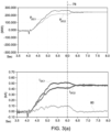
- a share factor D which is equal to 0.5 would result in a complementary share factor 1-D that is also equal to 0.5, such that the resulting changes to the phase angles of the first and second AC voltages V AC1 , V AC2 presented to the point of common coupling 40would give rise to the DC current I DC1 flowing in the first transmission conduit 18 being the same magnitude as the DC current I DC2 flowing in the second transmission conduit 20, i.e. each transmission conduit 18, 20 carrying half of the total DC current, as shown in Figure 3(a) .
- FIG. 3(a) shows that, upon the converter station controller 58 operating the first converter station 12 in the current distribution mode 78 (at a time of 6 seconds), adjusting the operating phase angle of the first AC voltage V AC1 presented to the point of common coupling 40 in a first direction, e.g. to increase the said phase angle, results in the DC current I DC1 flowing in the first transmission conduit 18 reducing, and adjusting the operating phase angle of the second AC voltage V AC2 presented to the point of common coupling 40 in a second direction opposite the first direction, e.g. to decrease the said phase angle by an equal but amount, results in the DC current I DC2 flowing in the second transmission conduit 20 increasing to the same magnitude as the DC current I DC1 flowing in the first transmission conduit 18.
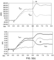
- a share factor D which is equal to 0.75 results in a complementary share factor 1-D that is equal to 0.25, such that the resulting changes to the phase angles of the first and second AC voltages V AC1 , V AC2 presented to the point of common coupling 40 give rise to a 75/25 sharing ratio between the DC current I DC1 flowing in the first transmission conduit 18 and the DC current I DC2 flowing in the second transmission conduit 20, i.e. approximately 75% of the total DC current flowing as a first DC current I DC1 in the first transmission conduit 18 and approximately 25% of the total DC current flowing as a second DC current I DC2 in the second transmission conduit 20.
- FIG. 3(b) similarly shows that, upon the converter station controller 58 operating the first converter station 12 in the current distribution mode 78 (at a time of 6 seconds), adjusting the operating phase angle of the first AC voltage V AC1 presented to the point of common coupling 40 in a different first direction, e.g. to decrease the said phase angle, results in the first DC current I DC1 flowing in the first transmission conduit 18 increasing to approximately 0.75 kA, and adjusting the operating phase angle of the second AC voltage V AC2 presented to the point of common coupling 40 in a different second direction opposite the first direction, e.g. to increase the said phase angle by an equal but opposite amount, results in the second DC current I DC2 flowing in the second transmission conduit 20 decreasing to approximately 0.25 kA.
- first and second DC currents I DC1 , I DC2 flowing in the first and second transmission conduits 18, 20 results in a non-negligible return conduit current 80 of about 0.5 kA.
- the converter station controller 58 may be programmed to determine the extent of operating phase angle adjustment in each of the first and second directions by establishing a measured return conduit current 80 and driving the measured return conduit current to a desired magnitude, i.e. by adjusting the operating phase angle of each of the first and second AC voltages V AC1 , V AC2 presented to the point of common coupling 40 in opposite directions, e.g. to increase one and decrease the other, so as to cause a corresponding respective increase or decrease in the first and second DC currents I DC1 , I DC2 flowing respectively in the first and second transmission conduits 18, 20 and thereby alter the measured return conduit current 80 to the desired level.
- the power source 38 is connected in parallel with a further AC network element in the form of an upstream AC network 82.
- the converter station controller 58 may be additionally programmed, while operating the first converter station 12 in the current distribution mode, to adjust the total amount of power transferred from the power source 38 into the first and second transmission conduits 18, 20 in order to control the power exchanged with the upstream AC network 82.
- converter station controller 58 may be so additionally programmed is by implementing a control algorithm of the closed-loop form shown schematically in Figure 4 .
- control algorithm shown in Figure 4 is very similar to the control algorithm shown in Figure 2 , and like elements share the same reference numerals.
- the Figure 4 algorithm differs, however, in that it additionally establishes a measured upstream AC network power transfer 84, i.e. the actual, measured power exchanged with the upstream AC network 82, and then adjusts the total amount of power transferred from the power source 38 into the first and second transmission conduits 18, 20 to drive the measured upstream AC network power transfer 84 to a desired magnitude, e.g. to drive the measured upstream AC network power transfer 84 to equal a desired power transfer reference 86.
- a measured upstream AC network power transfer 84 i.e. the actual, measured power exchanged with the upstream AC network 82
- the converter station controller 58 is programmed to subtract the measured upstream AC network power transfer 84 from the desired power transfer reference 86 to obtain a power transfer error value 88, which the converter station controller 58 then adds to the measured first and second transmission conduit currents 68, 70 to obtain a revised sum 66'.
- the converter station controller 58 is programmed to then establish a revised first reference current 64' (that the first power converter 30 is required to provide to the first transmission conduit 18) by applying a desired sharing factor D to the revised sum 66' to establish a revised first frequency change instruction 72' for the first power converter 30 which is again based on, i.e. derived from, a comparison of the revised first reference current 64' with the measured first transmission conduit current 68.
- the converter station controller 58 sends the revised first frequency change instruction 72' to the first converter controller 46 which, in turn, adjusts the phase angle of the first AC voltage V AC1 presented to the point of common coupling 40 to a desired extent and in a desired direction.
- the converter station controller 58 also similarly establishes a revised second reference current 74' (that the second power converter 48 is required to provide to the second transmission conduit 20) by applying a complementary sharing factor 1-D to the revised sum 66' to establish a revised second frequency change instruction 76' for the second power converter 48 which is again based on, i.e. derived from, a comparison of the revised second reference current 74' with the measured second transmission conduit current 70.
- the converter station controller 58 again similarly then sends the revised second frequency change instruction 76' to the second converter controller 56 which, in turn, adjusts the phase angle of the second AC voltage V AC2 presented to the point of common coupling 40 to a desired extent and in a desired direction.
- FIG. 5(a) shows balanced DC currents I DC1 , I DC2 and similar, balanced powers P DC1 , P DC2 of about 200 MW flowing in the first and second transmission conduits 18, 20 (and a commensurate, essentially zero, return conduit current 80). Meanwhile approximately 100 MW of power is diverted from the first and second transmission conduits 18, 20, e.g. in the form of a rejected power portion 90, and is therefore forced to flow into the upstream AC network 82.
- FIG. 5(b) Another example is illustrated in Figure 5(b) which again shows balanced DC currents I DC1 , I DC2 .
- approximately 100 MW of power is accepted from the upstream AC network 82, e.g. in the form of an absorbed power portion 92, and so larger, although still balanced, powers P DC1 , P DC2 of about 250 MW flow into each the first and second transmission conduits 18, 20.
- the converter station controller 58 may instead be programmed to adjust the total amount of power transferred from the power source 38 into the first and second transmission conduits 18, 20 by establishing a measured power source output, i.e. the actual measured power provided by the power source 38, and thereafter to adjust the total amount of power transferred from the power source 38 into the first and second transmission conduits 18, 20 to be a desired proportion of the measured power source output, i.e. such that the first and second power transmission conduits 18, 20 take a target proportion, e.g. 80%, of the power generated by the power source 38.
- a measured power source output i.e. the actual measured power provided by the power source 38
- a desired proportion of the measured power source output i.e. such that the first and second power transmission conduits 18, 20 take a target proportion, e.g. 80%, of the power generated by the power source 38.
- the converter station controller 58 preferably is additionally programmed to operate the first converter station 12 in a fault recovery mode prior to switching to operate the first converter station 12 in the current distribution mode after clearance of the fault.
- the converter station controller 58 will temporarily stop transmitting power via the affected transmission conduit 18, 20 so that the transmission conduit 18, 20 can be de-energised to facilitate clearance of the fault.
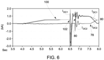
- Figure 6 shows that pre-fault operation 100 of the first converter station 12 is characterised by balancing of the first and second DC currents I DC1 , I DC2 between the first and second transmission conduits 18, 20.
- the second transmission conduit 20 When a fault occurs 102, e.g. in relation to the second transmission conduit 20, the second transmission conduit 20 is no longer able to transfer the second DC current I DC2 , but when the fault is detected the other healthy, i.e. first, transmission conduit 18 can be made to increase the first DC current I DC1 it carries (up to a maximum safe level), and hence also increase the first power P DC1 it transfers, to compensate for the loss of the faulted, second transmission conduit 20. In these circumstances, any power transfer that is beyond the capacity of the healthy, first transmission conduit 18 will have to be rejected, and hence will then flow into the upstream AC network 82 (when such an upstream AC network is included in the bipole power transmission scheme 10 of the invention).
- the imbalance the first and second DC currents I DC1 , I DC2 i.e. the increased first DC current I DC1 and the essentially zero second DC current I DC2 , causes a significant return conduit current 80 to flow.
- the first converter station 12 can be switched back to operating in the current distribution mode 78, whereby the first and second DC currents I DC1 , I DC2 are again balanced between the first and second transmission conduits 18, 20, and the return conduit current 80 falls back to essentially zero.
Landscapes
- Engineering & Computer Science (AREA)
- Power Engineering (AREA)
- Supply And Distribution Of Alternating Current (AREA)
Claims (12)
- Bipolares Leistungsübertragungsschema (10), das eine erste Wandlerstation (12) umfasst, die im Betrieb entfernt von einer zweiten Wandlerstation (14) positioniert ist, und erste und zweite Übertragungsleitungen (18, 20) und eine Rückleitung (22), um im Betrieb die erste Wandlerstation (12) mit der zweiten Wandlerstation (14) zu verbinden und dadurch den Transfer von Leistung (PDfC1, PDC2) zwischen der ersten und zweiten Wandlerstation (12, 14) zu erlauben,
wobei die erste Wandlerstation (12) beinhaltet:einen ersten Stromwandler (30), der einen ersten Gleichstromanschluss (32) aufweist, der mit der ersten Übertragungsleitung (18) verbunden ist, einen zweiten Gleichstromanschluss (34), der mit der Rückleitung (22) verbunden ist, und zumindest einen ersten Wechselstromanschluss (36), der mit einem gemeinsamen Kopplungspunkt (40) elektrisch verbunden ist, zum Verbinden mit einem Wechselstromnetzelement, das mit einem Referenzphasenwinkel arbeitet, wobei der erste Stromwandler (30) weiter eine erste Wandlersteuereinheit (46) aufweist, die programmiert ist, um den Transfer von Leistung zwischen der ersten Übertragungsleitung (18) und dem gemeinsamen Kopplungspunkt (40) zu steuern, indem der erste Stromwandler (30) an dem oder jedem ersten Wechselstromanschluss (36) eine erste Wechselspannung (VAC1) bereitstellt, die dem gemeinsamen Kopplungspunkt (40) zugeführt wird;einen zweiten Stromwandler (48), der einen dritten Gleichstromanschluss (50) aufweist, der mit der Rückleitung (22) verbunden ist, einen vierten Gleichstromanschluss (52), der mit der zweiten Übertragungsleitung (20) verbunden ist, und zumindest einen zweiten Wechselstromanschluss (54), der mit dem gemeinsamen Kopplungspunkt (40) elektrisch verbunden ist, wobei der zweite Stromwandler (48) weiter eine zweite Wandlersteuereinheit (56) aufweist, die programmiert ist, um den Transfer von Leistung zwischen der zweiten Übertragungsleitung (20) und dem gemeinsamen Kopplungspunkt (40) zu steuern, indem der zweite Stromwandler (48) an dem oder jedem zweiten Wechselstromanschluss (54) eine zweite Wechselspannung (VAC2) bereitstellt, die dem gemeinsamen Kopplungspunkt (40) zugeführt wird; undeine Wandlerstationsteuereinheit (58), die in operativer Verbindung mit jedem der ersten und zweiten Wandlersteuereinheit (46, 56) angeordnet ist, wodurch der erste und zweite Stromwandler (30, 48) als netzbildende Wandler gesteuert werden, sodass die erste und zweite Wechselspannung (VAC1, VAC2), die dem gemeinsamen Kopplungspunkt (40) zugeführt werden, die Wechselstromfrequenz (f) und die Wechselspannung (V) an dem gemeinsamen Kopplungspunkt (40) steuern,dadurch gekennzeichnet, dass
die Wandlerstationsteuereinheit (58) programmiert ist, um die erste Wandlerstation (12) in einem Stromverteilungsmodus (78) zu betreiben, in dem die Verteilung des Gleichstroms (IDC1, IDC2) zwischen der ersten und der zweiten Übertragungsleitung (18, 20) gesteuert wird, die Wandlerstationsteuereinheit (58) beim Betreiben der ersten Wandlerstation (12) in dem Stromverteilungsmodus (78) programmiert ist, um die erste Wandlersteuereinheit (46) anzuweisen, den Betriebsphasenwinkel der ersten Wechselspannung (VAC1), die an dem oder jedem ersten Wechselstromanschluss (36) bereitgestellt wird, in einer ersten Richtung in Bezug zum Referenzphasenwinkel an dem gemeinsamen Kopplungspunkt (40) anzupassen, und die zweite Wandlerstationsteuereinheit (56) anzuweisen, den Betriebsphasenwinkel der zweiten Wechselspannung (VAC2), die an dem oder jedem zweiten Wechselstromanschluss (54) bereitgestellt wird, in einer zweiten Richtung entgegengesetzt zu der ersten Richtung in Bezug zum Referenzphasenwinkel an dem gemeinsamen Kopplungspunkt (40) anzupassen. - Bipolares Leistungsübertragungsschema (10) nach Anspruch 1, wobei der gemeinsame Kopplungspunkt (40) mit einem Wechselstromnetzelement in Form einer Leistungsquelle (38) verbunden ist, die erste Wandlersteuereinheit (46) programmiert ist, um den Transfer von Leistung von der Leistungsquelle (38) zu der ersten Übertragungsleitung (18) zu steuern, und die zweite Wandlersteuereinheit (56) programmiert ist, um den Transfer von Leistung von der Leistungsquelle (38) zu der zweiten Übertragungsleitung (20) zu steuern.
- Bipolares Leistungsübertragungsschema (10) nach Anspruch 1 oder Anspruch 2, wobei die Wandlerstationsteuereinheit (58) programmiert ist, um den Umfang der Betriebsphasenwinkelanpassung in jeder von der ersten und der zweiten Richtung zu bestimmen.
- Bipolares Leistungsübertragungsschema (10) nach Anspruch 3, wobei die Wandlerstationsteuereinheit (58) konfiguriert ist, um den Umfang der Betriebsphasenwinkelanpassung in jeder von der ersten und der zweiten Richtung gemäß einem gewünschten Aufteilungsfaktor (D) zu bestimmen.
- Bipolares Leistungsübertragungsschema (10) nach Anspruch 4, wobei die Wandlerstationsteuereinheit (58):(i) konfiguriert ist, um einen ersten Referenzstrom (64) festzulegen, den der erste Stromwandler (30) der ersten Übertragungsleitung (18) durch Anwenden des gewünschten Aufteilungsfaktors (D) auf eine Summe (66) der gemessenen Ströme (68, 70) der ersten und zweiten Übertragungsleitung bereitstellen muss, und danach eine erste Änderungsanweisung (72) für den ersten Stromwandler (30) basierend auf einem Vergleich des ersten Referenzstroms (64) mit dem gemessenen Strom (68) der ersten Übertragungsleitung erstellt; und(ii) konfiguriert ist, um einen zweiten Referenzstrom (74) festzulegen, den der zweite Stromwandler (48) der zweiten Übertragungsleitung (20) durch Anwenden eines komplementären Aufteilungsfaktors (1-D) auf die Summe der gemessenen Ströme (68, 70) der ersten und zweiten Übertragungsleitung bereitstellen muss, und danach eine zweite Änderungsanweisung (76) für den zweiten Stromwandler (48) basierend auf einem Vergleich des zweiten Referenzstroms (74) mit dem gemessenen Strom (70) der zweiten Übertragungsleitung erstellt.
- Bipolares Leistungsübertragungsschema (10) nach Anspruch 5, wobei der komplementäre Aufteilungsfaktor (1-D) ausgewählt ist, um die gesamte Menge des Leistungstransfers zwischen dem gemeinsamen Kopplungspunkt (40) und der ersten und zweiten Übertragungsleitung (18, 20) während des Betriebs der ersten Wandlerstation (12) im Stromverteilungsmodus (78) auf dem gleichen Niveau zu halten wie das Niveau des Leistungstransfers vor dem Betrieb der ersten Wandlerstation (12) im Stromverteilungsmodus (78).
- Bipolares Leistungsübertragungsschema (10) nach Anspruch 3, wobei die Wandlerstationsteuereinheit (58) konfiguriert ist, um den Umfang der Betriebsphasenwinkelanpassung in jeder von der ersten und zweiten Richtung durch Aufbauen eines gemessenen Rückleitungsstroms und Ansteuern des gemessenen Rückleitungsstroms auf eine gewünschte Größe zu bestimmen.
- Bipolares Leistungsübertragungsschema (10) nach Anspruch 2 oder einem davon abhängigen Anspruch, wobei die Leistungsquelle (38) ein dazu parallel verbundenes vorgeschaltetes Wechselspannungsnetz (82) aufweist, und wobei die Wandlerstationsteuereinheit (58) während des Betriebs der ersten Wandlerstation (12) im Stromverteilungsmodus (78) zusätzlich programmiert ist, um die Gesamtmenge an Leistung anzupassen, die von der Leistungsquelle (38) in die erste und zweite Übertragungsleitung (18, 20) transferiert wird, um den mit dem vorgeschalteten Wechselspannungsnetz (82) ausgetauschten Strom zu steuern.
- Bipolares Leistungsübertragungsschema (10) nach Anspruch 8, wobei die Wandlerstationsteuereinheit (58) programmiert ist, um die Gesamtmenge an Leistung, die von der Leistungsquelle (38) in die erste und zweite Übertragungsleitung (18, 20) transferiert wird, durch Aufbauen eines gemessenen Transfers von Leistung in das vorgeschaltete Wechselspannungsnetz (84) Anpassen der Gesamtmenge an Leistung, die von der Leistungsquelle (38) in die erste und zweite Übertragungsleitung (18, 20) übertragen wird, anzupassen, um den gemessenen Transfer von Leistung in das vorgeschaltete Wechselspannungsnetz (84) auf eine gewünschte Größe anzusteuern.
- Bipolares Leistungsübertragungsschema (10) nach Anspruch 8, wobei die Wandlerstationsteuereinheit (58) programmiert ist, um die Gesamtmenge an Leistung, die von der Leistungsquelle (38) in die erste und zweite Übertragungsleitung (18, 20) übertragen wird, durch Aufbauen einer gemessenen Leistungsausgabe der Leistungsquelle und Anpassen der Gesamtmenge an Leistung, die von der Leistungsquelle (38) in die erste und zweite Übertragungsleitung (18, 20) übertragen wird, anzupassen, um einer gewünschten Größenordnung der gemessenen Leistungsausgabe des Leistungsquelle zu entsprechen.
- Bipolares Leistungsübertragungsschema (10) nach einem vorstehenden Anspruch, wobei die Wandlerstationsteuereinheit (58) zusätzlich programmiert ist, um die erste Wandlerstation (12) in einem Fehlerbeseitigungsmodus zu betreiben und nach der Beseitigung des Fehlers auf den Betrieb der ersten Wandlerstation (12) im Stromverteilungsmodus (78) umzuschalten.
- Verfahren zum Betreiben eines bipolaren Leistungsübertragungsschemas (10), das eine erste Wandlerstation (12) umfasst, die im Betrieb entfernt von einer zweiten Wandlerstation (14) positioniert ist, und erste und zweite Übertragungsleitungen (18, 20) und eine Rückleitung (22), um im Betrieb die erste Wandlerstation (12) mit der zweiten Wandlerstation (14) zu verbinden und dadurch den Transfer von Leistung (PDC1, PDC2) zwischen der ersten und zweiten Wandlerstation (12, 14) zu erlauben,wobei die erste Wandlerstation (14) beinhaltet:einen ersten Stromwandler (30), der einen ersten Gleichstromanschluss (32) aufweist, der mit der ersten Übertragungsleitung (18) verbunden ist, einen zweiten Gleichstromanschluss (34), der mit der Rückleitung (22) verbunden ist, und zumindest einen ersten Wechselstromanschluss (36), der mit einem gemeinsamen Kopplungspunkt (40) elektrisch verbunden ist, zum Verbinden mit einem Wechselstromnetzelement, das mit einem Referenzphasenwinkel arbeitet, wobei der erste Stromwandler (30) weiter eine erste Wandlersteuereinheit (46) aufweist, die programmiert ist, um den Transfer von Leistung zwischen der ersten Übertragungsleitung (18) und dem gemeinsamen Kopplungspunkt (40) zu steuern, indem der erste Stromwandler (30) an dem oder jedem ersten Wechselstromanschluss (36) eine erste Wechselspannung (VAC1) bereitstellt, die dem gemeinsamen Kopplungspunkt (40) zugeführt wird;einen zweiten Stromwandler (48), der einen dritten Gleichstromanschluss (50) aufweist, der mit der Rückleitung (22) verbunden ist, einen vierten Gleichstromanschluss (52), der mit der zweiten Übertragungsleitung (20) verbunden ist, und zumindest einen zweiten Wechselstromanschluss (54), der mit dem gemeinsamen Kopplungspunkt (40) elektrisch verbunden ist, wobei der zweite Stromwandler (48) weiter eine zweite Wandlersteuereinheit (56) aufweist, die programmiert ist, um den Transfer von Leistung zwischen der zweiten Übertragungsleitung (20) und dem gemeinsamen Kopplungspunkt (40) zu steuern, indem der zweite Stromwandler (48) an dem oder jedem zweiten Wechselstromanschluss (54) eine zweite Wechselspannung (VAC2) bereitstellt, die dem gemeinsamen Kopplungspunkt (40) zugeführt wird; unddadurch gekennzeichnet, dass
eine Wandlerstationsteuereinheit (58), die in operativer Verbindung mit jedem der ersten und zweiten Wandlersteuereinheit (46, 56) angeordnet ist, wodurch der erste und zweite Stromwandler (30, 48) als netzbildende Wandler gesteuert werden, sodass die erste und zweite Wechselspannung (VAC1, VAC2), die dem gemeinsamen Kopplungspunkt (40) zugeführt werden, die Wechselstromfrequenz (f) und die Wechselspannung (V) an dem gemeinsamen Kopplungspunkt (40) steuern,wobei das Verfahren den Schritt des Betreibens der ersten Wandlerstation (12) in einem Stromverteilungsmodus (78) zu betreiben, in dem die Verteilung des Gleichstroms (IDC1, IDC2) zwischen der ersten und der zweiten Übertragungsleitung (18, 20) gesteuert wird, indem die Wandlerstationsteuereinheit (58) die erste Wandlersteuereinheit (46) angewiesen hat, den Betriebsphasenwinkel der ersten Wechselspannung (VAC1), die an dem oder jedem ersten Wechselstromanschluss (36) bereitgestellt wird, in einer ersten Richtung in Bezug zum Referenzphasenwinkel an dem gemeinsamen Kopplungspunkt (40) anzupassen, und die zweite Wandlerstationsteuereinheit (56) anzuweisen, den Betriebsphasenwinkel der zweiten Wechselspannung (VAC2), die an dem oder jedem zweiten Wechselstromanschluss (54) bereitgestellt wird, in einer zweiten Richtung entgegengesetzt zu der ersten Richtung in Bezug zum Referenzphasenwinkel an dem gemeinsamen Kopplungspunkt (40) anzupassen.
Priority Applications (4)
| Application Number | Priority Date | Filing Date | Title |
|---|---|---|---|
| DK21275161.4T DK4184739T3 (da) | 2021-11-18 | 2021-11-18 | Forbedringer i eller vedrørende bipolære effektoverførselssystemer |
| EP21275161.4A EP4184739B1 (de) | 2021-11-18 | 2021-11-18 | Verbesserungen an oder im zusammenhang mit bipolaren stromübertragungsschemen |
| US18/053,724 US12009757B2 (en) | 2021-11-18 | 2022-11-08 | Relating to bipole power transmission schemes |
| CN202211442777.4A CN116137443A (zh) | 2021-11-18 | 2022-11-18 | 双极功率传输方案中的改进或与其相关的改进 |
Applications Claiming Priority (1)
| Application Number | Priority Date | Filing Date | Title |
|---|---|---|---|
| EP21275161.4A EP4184739B1 (de) | 2021-11-18 | 2021-11-18 | Verbesserungen an oder im zusammenhang mit bipolaren stromübertragungsschemen |
Publications (2)
| Publication Number | Publication Date |
|---|---|
| EP4184739A1 EP4184739A1 (de) | 2023-05-24 |
| EP4184739B1 true EP4184739B1 (de) | 2025-06-18 |
Family
ID=78709372
Family Applications (1)
| Application Number | Title | Priority Date | Filing Date |
|---|---|---|---|
| EP21275161.4A Active EP4184739B1 (de) | 2021-11-18 | 2021-11-18 | Verbesserungen an oder im zusammenhang mit bipolaren stromübertragungsschemen |
Country Status (4)
| Country | Link |
|---|---|
| US (1) | US12009757B2 (de) |
| EP (1) | EP4184739B1 (de) |
| CN (1) | CN116137443A (de) |
| DK (1) | DK4184739T3 (de) |
Families Citing this family (7)
| Publication number | Priority date | Publication date | Assignee | Title |
|---|---|---|---|---|
| EP3975370B1 (de) * | 2020-09-25 | 2024-07-31 | General Electric Technology GmbH | Verbesserungen an oder im zusammenhang mit stromübertragungsnetzwerken |
| EP4184739B1 (de) * | 2021-11-18 | 2025-06-18 | General Electric Technology GmbH | Verbesserungen an oder im zusammenhang mit bipolaren stromübertragungsschemen |
| EP4254706A1 (de) * | 2022-03-29 | 2023-10-04 | General Electric Technology GmbH | Verbesserungen an oder im zusammenhang mit bipolaren stromübertragungsnetzen |
| US12149085B1 (en) | 2023-07-14 | 2024-11-19 | Ge Infrastructure Technology Llc | Bipole power transmission schemes |
| US12149156B1 (en) | 2023-07-14 | 2024-11-19 | Ge Infrastructure Technology Llc | Bipole power transmission schemes |
| EP4560865A1 (de) * | 2023-11-24 | 2025-05-28 | General Electric Technology GmbH | Verbesserungen im zusammenhang mit der steuerung von zweipoligen stromübertragungsnetzwerken |
| EP4636977A1 (de) * | 2024-04-15 | 2025-10-22 | GE Vernova Technology GmbH | Verbesserungen in bezug auf starre zweipolige stromübertragungsnetze |
Family Cites Families (6)
| Publication number | Priority date | Publication date | Assignee | Title |
|---|---|---|---|---|
| DK2713468T3 (da) * | 2012-09-28 | 2019-11-04 | Ge Energy Power Conversion Technology Ltd | Elektriske energioverførselssystemer |
| GB2536894B (en) | 2015-03-30 | 2021-06-23 | General Electric Technology Gmbh | Converters |
| JP6831037B2 (ja) * | 2017-08-03 | 2021-02-17 | アー・ベー・ベー・パワー・グリッズ・スウィツァーランド・アクチェンゲゼルシャフトAbb Power Grids Switzerland Ag | Dcシステムにおいて電圧源変換器を制御すること |
| EP3913762A1 (de) * | 2020-05-22 | 2021-11-24 | General Electric Technology GmbH | Bipol-hgü-stromübertragungssystem, konfigurierbar für monopolbetrieb |
| EP4184739B1 (de) * | 2021-11-18 | 2025-06-18 | General Electric Technology GmbH | Verbesserungen an oder im zusammenhang mit bipolaren stromübertragungsschemen |
| EP4254706A1 (de) * | 2022-03-29 | 2023-10-04 | General Electric Technology GmbH | Verbesserungen an oder im zusammenhang mit bipolaren stromübertragungsnetzen |
-
2021
- 2021-11-18 EP EP21275161.4A patent/EP4184739B1/de active Active
- 2021-11-18 DK DK21275161.4T patent/DK4184739T3/da active
-
2022
- 2022-11-08 US US18/053,724 patent/US12009757B2/en active Active
- 2022-11-18 CN CN202211442777.4A patent/CN116137443A/zh active Pending
Also Published As
| Publication number | Publication date |
|---|---|
| US20230082909A1 (en) | 2023-03-16 |
| EP4184739A1 (de) | 2023-05-24 |
| US12009757B2 (en) | 2024-06-11 |
| DK4184739T3 (da) | 2025-06-30 |
| CN116137443A (zh) | 2023-05-19 |
Similar Documents
| Publication | Publication Date | Title |
|---|---|---|
| EP4184739B1 (de) | Verbesserungen an oder im zusammenhang mit bipolaren stromübertragungsschemen | |
| KR102686834B1 (ko) | 전기 그리드를 자력 기동하는 방법 | |
| Bahrman et al. | The ABCs of HVDC transmission technologies | |
| Rao | Architecture of Nan'ao multi-terminal VSC-HVDC system and its multi-functional control | |
| EP3367547B1 (de) | Blindleistungs-intra-area-master-steuergerät für fest gekoppelte windfarmen | |
| AU2015377905B2 (en) | Power distribution on a vessel | |
| US10038321B2 (en) | System for operation of photovoltaic power plant and DC power collection within | |
| US9041248B2 (en) | Control of the distribution of electric power generated by a wind farm between an AC power transmission link and a DC power transmission link | |
| US12272955B2 (en) | Bipole power transmission schemes | |
| KR102822817B1 (ko) | 전기 그리드를 자력 기동하는 방법 | |
| US20180097450A1 (en) | Hybrid high voltage direct current converter station and operation method therefor | |
| US10411616B2 (en) | Controlling a power transmission network | |
| WO2016146795A1 (en) | Power transmission network | |
| Marczewski | VFT applications between grid control areas | |
| CN108701995A (zh) | 功率转换电路、电力系统及其方法 | |
| Varma et al. | Multimode control of PV-STATCOM for stabilization of remote critical induction motor | |
| Fischer de Toledo | Feasibility of HVDC for city infeed | |
| Teeuwsen et al. | Dynamic performance of the 1000 MW BritNed HVDC interconnector project | |
| Kamalapur et al. | A comparative study of Monopolar and Bipolar HVDC transmission systems | |
| Cartwright et al. | The integration of large scale wind power generation into transmission networks using power electronics | |
| Castro et al. | „Co-ordination of parallel AC-DC systems for optimum performance | |
| Alhomsi et al. | AC System Restoration Using Embedded MT-HVDC | |
| US20260121416A1 (en) | HVDC TRANSFORMER CONFIGURATION FOR SPLIT PCCs | |
| US20260128594A1 (en) | System and method for dynamic grid control | |
| Cartwright et al. | Grid compliant offshore wind power connections provided by FACTS and HVDC solutions |
Legal Events
| Date | Code | Title | Description |
|---|---|---|---|
| PUAI | Public reference made under article 153(3) epc to a published international application that has entered the european phase |
Free format text: ORIGINAL CODE: 0009012 |
|
| STAA | Information on the status of an ep patent application or granted ep patent |
Free format text: STATUS: THE APPLICATION HAS BEEN PUBLISHED |
|
| AK | Designated contracting states |
Kind code of ref document: A1 Designated state(s): AL AT BE BG CH CY CZ DE DK EE ES FI FR GB GR HR HU IE IS IT LI LT LU LV MC MK MT NL NO PL PT RO RS SE SI SK SM TR |
|
| STAA | Information on the status of an ep patent application or granted ep patent |
Free format text: STATUS: REQUEST FOR EXAMINATION WAS MADE |
|
| 17P | Request for examination filed |
Effective date: 20230928 |
|
| RBV | Designated contracting states (corrected) |
Designated state(s): AL AT BE BG CH CY CZ DE DK EE ES FI FR GB GR HR HU IE IS IT LI LT LU LV MC MK MT NL NO PL PT RO RS SE SI SK SM TR |
|
| GRAP | Despatch of communication of intention to grant a patent |
Free format text: ORIGINAL CODE: EPIDOSNIGR1 |
|
| STAA | Information on the status of an ep patent application or granted ep patent |
Free format text: STATUS: GRANT OF PATENT IS INTENDED |
|
| INTG | Intention to grant announced |
Effective date: 20250206 |
|
| GRAS | Grant fee paid |
Free format text: ORIGINAL CODE: EPIDOSNIGR3 |
|
| GRAA | (expected) grant |
Free format text: ORIGINAL CODE: 0009210 |
|
| STAA | Information on the status of an ep patent application or granted ep patent |
Free format text: STATUS: THE PATENT HAS BEEN GRANTED |
|
| AK | Designated contracting states |
Kind code of ref document: B1 Designated state(s): AL AT BE BG CH CY CZ DE DK EE ES FI FR GB GR HR HU IE IS IT LI LT LU LV MC MK MT NL NO PL PT RO RS SE SI SK SM TR |
|
| REG | Reference to a national code |
Ref country code: GB Ref legal event code: FG4D |
|
| REG | Reference to a national code |
Ref country code: DK Ref legal event code: T3 Effective date: 20250626 Ref country code: CH Ref legal event code: EP |
|
| REG | Reference to a national code |
Ref country code: DE Ref legal event code: R096 Ref document number: 602021032416 Country of ref document: DE |
|
| REG | Reference to a national code |
Ref country code: CH Ref legal event code: EP |
|
| REG | Reference to a national code |
Ref country code: IE Ref legal event code: FG4D |
|
| REG | Reference to a national code |
Ref country code: SE Ref legal event code: TRGR |
|
| REG | Reference to a national code |
Ref country code: NL Ref legal event code: FP |
|
| P01 | Opt-out of the competence of the unified patent court (upc) registered |
Free format text: CASE NUMBER: APP_32248/2025 Effective date: 20250701 |
|
| RAP4 | Party data changed (patent owner data changed or rights of a patent transferred) |
Owner name: GE VERNOVA TECHNOLOGY GMBH |
|
| PG25 | Lapsed in a contracting state [announced via postgrant information from national office to epo] |
Ref country code: FI Free format text: LAPSE BECAUSE OF FAILURE TO SUBMIT A TRANSLATION OF THE DESCRIPTION OR TO PAY THE FEE WITHIN THE PRESCRIBED TIME-LIMIT Effective date: 20250618 |
|
| REG | Reference to a national code |
Ref country code: LT Ref legal event code: MG9D |
|
| PG25 | Lapsed in a contracting state [announced via postgrant information from national office to epo] |
Ref country code: NO Free format text: LAPSE BECAUSE OF FAILURE TO SUBMIT A TRANSLATION OF THE DESCRIPTION OR TO PAY THE FEE WITHIN THE PRESCRIBED TIME-LIMIT Effective date: 20250918 Ref country code: GR Free format text: LAPSE BECAUSE OF FAILURE TO SUBMIT A TRANSLATION OF THE DESCRIPTION OR TO PAY THE FEE WITHIN THE PRESCRIBED TIME-LIMIT Effective date: 20250919 |
|
| PG25 | Lapsed in a contracting state [announced via postgrant information from national office to epo] |
Ref country code: BG Free format text: LAPSE BECAUSE OF FAILURE TO SUBMIT A TRANSLATION OF THE DESCRIPTION OR TO PAY THE FEE WITHIN THE PRESCRIBED TIME-LIMIT Effective date: 20250618 |
|
| PG25 | Lapsed in a contracting state [announced via postgrant information from national office to epo] |
Ref country code: HR Free format text: LAPSE BECAUSE OF FAILURE TO SUBMIT A TRANSLATION OF THE DESCRIPTION OR TO PAY THE FEE WITHIN THE PRESCRIBED TIME-LIMIT Effective date: 20250618 |
|
| PG25 | Lapsed in a contracting state [announced via postgrant information from national office to epo] |
Ref country code: RS Free format text: LAPSE BECAUSE OF FAILURE TO SUBMIT A TRANSLATION OF THE DESCRIPTION OR TO PAY THE FEE WITHIN THE PRESCRIBED TIME-LIMIT Effective date: 20250918 |
|
| PG25 | Lapsed in a contracting state [announced via postgrant information from national office to epo] |
Ref country code: LV Free format text: LAPSE BECAUSE OF FAILURE TO SUBMIT A TRANSLATION OF THE DESCRIPTION OR TO PAY THE FEE WITHIN THE PRESCRIBED TIME-LIMIT Effective date: 20250618 |
|
| PGFP | Annual fee paid to national office [announced via postgrant information from national office to epo] |
Ref country code: NL Payment date: 20251022 Year of fee payment: 5 |
|
| PG25 | Lapsed in a contracting state [announced via postgrant information from national office to epo] |
Ref country code: PT Free format text: LAPSE BECAUSE OF FAILURE TO SUBMIT A TRANSLATION OF THE DESCRIPTION OR TO PAY THE FEE WITHIN THE PRESCRIBED TIME-LIMIT Effective date: 20251020 |
|
| REG | Reference to a national code |
Ref country code: AT Ref legal event code: MK05 Ref document number: 1805126 Country of ref document: AT Kind code of ref document: T Effective date: 20250618 |
|
| PG25 | Lapsed in a contracting state [announced via postgrant information from national office to epo] |
Ref country code: IS Free format text: LAPSE BECAUSE OF FAILURE TO SUBMIT A TRANSLATION OF THE DESCRIPTION OR TO PAY THE FEE WITHIN THE PRESCRIBED TIME-LIMIT Effective date: 20251018 |
|
| PGFP | Annual fee paid to national office [announced via postgrant information from national office to epo] |
Ref country code: DE Payment date: 20251022 Year of fee payment: 5 |
|
| PGFP | Annual fee paid to national office [announced via postgrant information from national office to epo] |
Ref country code: GB Payment date: 20251023 Year of fee payment: 5 |
|
| PG25 | Lapsed in a contracting state [announced via postgrant information from national office to epo] |
Ref country code: AT Free format text: LAPSE BECAUSE OF FAILURE TO SUBMIT A TRANSLATION OF THE DESCRIPTION OR TO PAY THE FEE WITHIN THE PRESCRIBED TIME-LIMIT Effective date: 20250618 Ref country code: SM Free format text: LAPSE BECAUSE OF FAILURE TO SUBMIT A TRANSLATION OF THE DESCRIPTION OR TO PAY THE FEE WITHIN THE PRESCRIBED TIME-LIMIT Effective date: 20250618 |
|
| PGFP | Annual fee paid to national office [announced via postgrant information from national office to epo] |
Ref country code: DK Payment date: 20251022 Year of fee payment: 5 |
|
| PGFP | Annual fee paid to national office [announced via postgrant information from national office to epo] |
Ref country code: FR Payment date: 20251022 Year of fee payment: 5 |
|
| PGFP | Annual fee paid to national office [announced via postgrant information from national office to epo] |
Ref country code: BE Payment date: 20251022 Year of fee payment: 5 |
|
| PGFP | Annual fee paid to national office [announced via postgrant information from national office to epo] |
Ref country code: SE Payment date: 20251022 Year of fee payment: 5 |
|
| PG25 | Lapsed in a contracting state [announced via postgrant information from national office to epo] |
Ref country code: CZ Free format text: LAPSE BECAUSE OF FAILURE TO SUBMIT A TRANSLATION OF THE DESCRIPTION OR TO PAY THE FEE WITHIN THE PRESCRIBED TIME-LIMIT Effective date: 20250618 |
|
| PG25 | Lapsed in a contracting state [announced via postgrant information from national office to epo] |
Ref country code: PL Free format text: LAPSE BECAUSE OF FAILURE TO SUBMIT A TRANSLATION OF THE DESCRIPTION OR TO PAY THE FEE WITHIN THE PRESCRIBED TIME-LIMIT Effective date: 20250618 |
|
| PG25 | Lapsed in a contracting state [announced via postgrant information from national office to epo] |
Ref country code: EE Free format text: LAPSE BECAUSE OF FAILURE TO SUBMIT A TRANSLATION OF THE DESCRIPTION OR TO PAY THE FEE WITHIN THE PRESCRIBED TIME-LIMIT Effective date: 20250618 |
|
| PG25 | Lapsed in a contracting state [announced via postgrant information from national office to epo] |
Ref country code: SK Free format text: LAPSE BECAUSE OF FAILURE TO SUBMIT A TRANSLATION OF THE DESCRIPTION OR TO PAY THE FEE WITHIN THE PRESCRIBED TIME-LIMIT Effective date: 20250618 |
|
| PG25 | Lapsed in a contracting state [announced via postgrant information from national office to epo] |
Ref country code: ES Free format text: LAPSE BECAUSE OF FAILURE TO SUBMIT A TRANSLATION OF THE DESCRIPTION OR TO PAY THE FEE WITHIN THE PRESCRIBED TIME-LIMIT Effective date: 20250618 |
|
| PG25 | Lapsed in a contracting state [announced via postgrant information from national office to epo] |
Ref country code: RO Free format text: LAPSE BECAUSE OF FAILURE TO SUBMIT A TRANSLATION OF THE DESCRIPTION OR TO PAY THE FEE WITHIN THE PRESCRIBED TIME-LIMIT Effective date: 20250618 |
|
| PG25 | Lapsed in a contracting state [announced via postgrant information from national office to epo] |
Ref country code: IT Free format text: LAPSE BECAUSE OF FAILURE TO SUBMIT A TRANSLATION OF THE DESCRIPTION OR TO PAY THE FEE WITHIN THE PRESCRIBED TIME-LIMIT Effective date: 20250618 |
|
| PLBE | No opposition filed within time limit |
Free format text: ORIGINAL CODE: 0009261 |
|
| STAA | Information on the status of an ep patent application or granted ep patent |
Free format text: STATUS: NO OPPOSITION FILED WITHIN TIME LIMIT |
|
| REG | Reference to a national code |
Ref country code: CH Ref legal event code: L10 Free format text: ST27 STATUS EVENT CODE: U-0-0-L10-L00 (AS PROVIDED BY THE NATIONAL OFFICE) Effective date: 20260430 |