EP4184693A1 - Secondary battery and manufacturing method for same - Google Patents
Secondary battery and manufacturing method for same Download PDFInfo
- Publication number
- EP4184693A1 EP4184693A1 EP21911230.7A EP21911230A EP4184693A1 EP 4184693 A1 EP4184693 A1 EP 4184693A1 EP 21911230 A EP21911230 A EP 21911230A EP 4184693 A1 EP4184693 A1 EP 4184693A1
- Authority
- EP
- European Patent Office
- Prior art keywords
- safety vent
- secondary battery
- manufacturing
- cap assembly
- notch portion
- Prior art date
- Legal status (The legal status is an assumption and is not a legal conclusion. Google has not performed a legal analysis and makes no representation as to the accuracy of the status listed.)
- Granted
Links
Images




Classifications
-
- H—ELECTRICITY
- H01—ELECTRIC ELEMENTS
- H01M—PROCESSES OR MEANS, e.g. BATTERIES, FOR THE DIRECT CONVERSION OF CHEMICAL ENERGY INTO ELECTRICAL ENERGY
- H01M50/00—Constructional details or processes of manufacture of the non-active parts of electrochemical cells other than fuel cells, e.g. hybrid cells
- H01M50/30—Arrangements for facilitating escape of gases
- H01M50/342—Non-re-sealable arrangements
-
- H—ELECTRICITY
- H01—ELECTRIC ELEMENTS
- H01M—PROCESSES OR MEANS, e.g. BATTERIES, FOR THE DIRECT CONVERSION OF CHEMICAL ENERGY INTO ELECTRICAL ENERGY
- H01M50/00—Constructional details or processes of manufacture of the non-active parts of electrochemical cells other than fuel cells, e.g. hybrid cells
- H01M50/30—Arrangements for facilitating escape of gases
- H01M50/342—Non-re-sealable arrangements
- H01M50/3425—Non-re-sealable arrangements in the form of rupturable membranes or weakened parts, e.g. pierced with the aid of a sharp member
-
- H—ELECTRICITY
- H01—ELECTRIC ELEMENTS
- H01M—PROCESSES OR MEANS, e.g. BATTERIES, FOR THE DIRECT CONVERSION OF CHEMICAL ENERGY INTO ELECTRICAL ENERGY
- H01M10/00—Secondary cells; Manufacture thereof
- H01M10/05—Accumulators with non-aqueous electrolyte
- H01M10/052—Li-accumulators
- H01M10/0525—Rocking-chair batteries, i.e. batteries with lithium insertion or intercalation in both electrodes; Lithium-ion batteries
-
- H—ELECTRICITY
- H01—ELECTRIC ELEMENTS
- H01M—PROCESSES OR MEANS, e.g. BATTERIES, FOR THE DIRECT CONVERSION OF CHEMICAL ENERGY INTO ELECTRICAL ENERGY
- H01M50/00—Constructional details or processes of manufacture of the non-active parts of electrochemical cells other than fuel cells, e.g. hybrid cells
- H01M50/10—Primary casings; Jackets or wrappings
- H01M50/102—Primary casings; Jackets or wrappings characterised by their shape or physical structure
- H01M50/107—Primary casings; Jackets or wrappings characterised by their shape or physical structure having curved cross-section, e.g. round or elliptic
-
- H—ELECTRICITY
- H01—ELECTRIC ELEMENTS
- H01M—PROCESSES OR MEANS, e.g. BATTERIES, FOR THE DIRECT CONVERSION OF CHEMICAL ENERGY INTO ELECTRICAL ENERGY
- H01M50/00—Constructional details or processes of manufacture of the non-active parts of electrochemical cells other than fuel cells, e.g. hybrid cells
- H01M50/10—Primary casings; Jackets or wrappings
- H01M50/147—Lids or covers
-
- H—ELECTRICITY
- H01—ELECTRIC ELEMENTS
- H01M—PROCESSES OR MEANS, e.g. BATTERIES, FOR THE DIRECT CONVERSION OF CHEMICAL ENERGY INTO ELECTRICAL ENERGY
- H01M50/00—Constructional details or processes of manufacture of the non-active parts of electrochemical cells other than fuel cells, e.g. hybrid cells
- H01M50/10—Primary casings; Jackets or wrappings
- H01M50/147—Lids or covers
- H01M50/148—Lids or covers characterised by their shape
- H01M50/15—Lids or covers characterised by their shape for prismatic or rectangular cells
-
- H—ELECTRICITY
- H01—ELECTRIC ELEMENTS
- H01M—PROCESSES OR MEANS, e.g. BATTERIES, FOR THE DIRECT CONVERSION OF CHEMICAL ENERGY INTO ELECTRICAL ENERGY
- H01M50/00—Constructional details or processes of manufacture of the non-active parts of electrochemical cells other than fuel cells, e.g. hybrid cells
- H01M50/10—Primary casings; Jackets or wrappings
- H01M50/147—Lids or covers
- H01M50/148—Lids or covers characterised by their shape
- H01M50/152—Lids or covers characterised by their shape for cells having curved cross-section, e.g. round or elliptic
-
- H—ELECTRICITY
- H01—ELECTRIC ELEMENTS
- H01M—PROCESSES OR MEANS, e.g. BATTERIES, FOR THE DIRECT CONVERSION OF CHEMICAL ENERGY INTO ELECTRICAL ENERGY
- H01M50/00—Constructional details or processes of manufacture of the non-active parts of electrochemical cells other than fuel cells, e.g. hybrid cells
- H01M50/10—Primary casings; Jackets or wrappings
- H01M50/147—Lids or covers
- H01M50/166—Lids or covers characterised by the methods of assembling casings with lids
- H01M50/167—Lids or covers characterised by the methods of assembling casings with lids by crimping
-
- H—ELECTRICITY
- H01—ELECTRIC ELEMENTS
- H01M—PROCESSES OR MEANS, e.g. BATTERIES, FOR THE DIRECT CONVERSION OF CHEMICAL ENERGY INTO ELECTRICAL ENERGY
- H01M50/00—Constructional details or processes of manufacture of the non-active parts of electrochemical cells other than fuel cells, e.g. hybrid cells
- H01M50/10—Primary casings; Jackets or wrappings
- H01M50/147—Lids or covers
- H01M50/166—Lids or covers characterised by the methods of assembling casings with lids
- H01M50/169—Lids or covers characterised by the methods of assembling casings with lids by welding, brazing or soldering
-
- H—ELECTRICITY
- H01—ELECTRIC ELEMENTS
- H01M—PROCESSES OR MEANS, e.g. BATTERIES, FOR THE DIRECT CONVERSION OF CHEMICAL ENERGY INTO ELECTRICAL ENERGY
- H01M50/00—Constructional details or processes of manufacture of the non-active parts of electrochemical cells other than fuel cells, e.g. hybrid cells
- H01M50/10—Primary casings; Jackets or wrappings
- H01M50/147—Lids or covers
- H01M50/166—Lids or covers characterised by the methods of assembling casings with lids
- H01M50/171—Lids or covers characterised by the methods of assembling casings with lids using adhesives or sealing agents
-
- H—ELECTRICITY
- H01—ELECTRIC ELEMENTS
- H01M—PROCESSES OR MEANS, e.g. BATTERIES, FOR THE DIRECT CONVERSION OF CHEMICAL ENERGY INTO ELECTRICAL ENERGY
- H01M50/00—Constructional details or processes of manufacture of the non-active parts of electrochemical cells other than fuel cells, e.g. hybrid cells
- H01M50/30—Arrangements for facilitating escape of gases
-
- H—ELECTRICITY
- H01—ELECTRIC ELEMENTS
- H01M—PROCESSES OR MEANS, e.g. BATTERIES, FOR THE DIRECT CONVERSION OF CHEMICAL ENERGY INTO ELECTRICAL ENERGY
- H01M50/00—Constructional details or processes of manufacture of the non-active parts of electrochemical cells other than fuel cells, e.g. hybrid cells
- H01M50/50—Current conducting connections for cells or batteries
- H01M50/572—Means for preventing undesired use or discharge
- H01M50/574—Devices or arrangements for the interruption of current
- H01M50/578—Devices or arrangements for the interruption of current in response to pressure
-
- H—ELECTRICITY
- H01—ELECTRIC ELEMENTS
- H01M—PROCESSES OR MEANS, e.g. BATTERIES, FOR THE DIRECT CONVERSION OF CHEMICAL ENERGY INTO ELECTRICAL ENERGY
- H01M2200/00—Safety devices for primary or secondary batteries
- H01M2200/20—Pressure-sensitive devices
-
- Y—GENERAL TAGGING OF NEW TECHNOLOGICAL DEVELOPMENTS; GENERAL TAGGING OF CROSS-SECTIONAL TECHNOLOGIES SPANNING OVER SEVERAL SECTIONS OF THE IPC; TECHNICAL SUBJECTS COVERED BY FORMER USPC CROSS-REFERENCE ART COLLECTIONS [XRACs] AND DIGESTS
- Y02—TECHNOLOGIES OR APPLICATIONS FOR MITIGATION OR ADAPTATION AGAINST CLIMATE CHANGE
- Y02E—REDUCTION OF GREENHOUSE GAS [GHG] EMISSIONS, RELATED TO ENERGY GENERATION, TRANSMISSION OR DISTRIBUTION
- Y02E60/00—Enabling technologies; Technologies with a potential or indirect contribution to GHG emissions mitigation
- Y02E60/10—Energy storage using batteries
-
- Y—GENERAL TAGGING OF NEW TECHNOLOGICAL DEVELOPMENTS; GENERAL TAGGING OF CROSS-SECTIONAL TECHNOLOGIES SPANNING OVER SEVERAL SECTIONS OF THE IPC; TECHNICAL SUBJECTS COVERED BY FORMER USPC CROSS-REFERENCE ART COLLECTIONS [XRACs] AND DIGESTS
- Y02—TECHNOLOGIES OR APPLICATIONS FOR MITIGATION OR ADAPTATION AGAINST CLIMATE CHANGE
- Y02P—CLIMATE CHANGE MITIGATION TECHNOLOGIES IN THE PRODUCTION OR PROCESSING OF GOODS
- Y02P70/00—Climate change mitigation technologies in the production process for final industrial or consumer products
- Y02P70/50—Manufacturing or production processes characterised by the final manufactured product
Definitions
- the present disclosure relates to a secondary battery and a method for manufacturing the same, and more particularly, to a secondary battery with improved vibration resistance and a method for manufacturing the same.
- the demand for the lithium secondary battery such as a lithium ion battery or a lithium ion polymer battery, which have advantages such as a high energy density, a discharge voltage, an output stability, and the like is high.
- the secondary battery may be classified based on the structure of an electrode assembly having a structure in which a cathode and an anode are stacked with a separator being interposed therebetween.
- an electrode assembly having a structure in which a cathode and an anode are stacked with a separator being interposed therebetween.
- a jelly-roll type electrode assembly having a structure in which long sheets of cathodes and anodes are wound in the state in which a separator is interposed therebetween
- a stacked type electrode assembly having a structure in which pluralities of cathodes and anodes, cut by a certain size unit, are sequentially stacked in the state in which separators are interposed therebetween, or the like.
- a stacked/folded type electrode assembly which is a combination of the jelly-roll type electrode assembly and the stacked type electrode assembly, having a structure in which unit cells stacked with predetermined units of the cathodes and the anodes are sequentially wound with a separator being interposed therebetween in the state of having been placed on a separation film.
- the secondary battery is classified into a cylindrical battery where an electrode assembly is mounted in a cylindrical case, a prismatic battery where an electrode assembly is mounted in a prismatic can, and a pouch type battery where an electrode assembly is mounted in a pouch type case of an aluminum laminate sheet.
- a secondary battery can be suitably used in the market as long as it satisfies performance suitable for the intended use and at the same time, has safety.
- the design factors are determined in consideration of these performance and safety aspects at the same time. Batteries whose design and manufacturing are completed are subjected to performance evaluations such as lifespan, high rate characteristics, and high/low temperature characteristics, as well as to safety evaluations such as overcharge, over-discharge, impact, nail test, and hot box.
- a cylindrical secondary battery may include a current interrupt device (CID) that interrupts the current between the electrode terminal and the electrode tab to prevent additional reactions, when gas is suddenly generated inside the secondary battery in an abnormal state such as overcharge and the internal pressure exceeds a certain level.
- CID current interrupt device
- Fig. 1 is a partial cross-sectional view which shows a cross-section of the upper part of a conventional cylindrical secondary battery.
- a cylindrical secondary battery 10 can be manufactured by housing an electrode assembly 20 in a cylindrical case 30, and mounting a cap assembly 40 onto the opened upper part of the cylindrical case 30.
- the electrode assembly 20 may be a jelly-roll type electrode assembly in which a first electrode 21, a second electrode 22, and a separator 23 are wound.
- the cap assembly 40 may include an upper end cap 41, an internal pressure drop safety vent 42 and a current interrupt device (CID) 43.
- the upper end cap 41 and the safety vent 42 can form a structure in close contact with each other, and the safety vent 42 can be connected to the central part of the current interrupt device 43.
- a first electrode tab 21t protruding from the first electrode 21 can be connected to the lower end part of the current interrupt device 43.
- the first electrode 21 may be a cathode
- the first electrode tab 21t may be a cathode tab.
- the upper end cap 41 can be directly or indirectly connected to the safety vent 42, the current interrupt device 43 and the first electrode tabs 21t to be electrically connected to the electrode assembly 20, and can function as an electrode terminal.
- a gasket 70 for sealing between the cap assembly 40 and the cylindrical case 30 and a CID gasket 80 for wrapping the edge of the current interrupt device 43 may be arranged.
- Fig. 2 is a partial cross-sectional view which shows a state when the internal pressure of the cylindrical secondary battery of Fig. 1 is increased.
- the shape of the safety vent 42 is reversed, and the current interrupt device 43 is separated to interrupt the current.
- the current interrupt device 43 is divided into a portion 43a connected to the safety vent 42 and a portion 43b connected to the first electrode tab 21t, so that the flow of current between the upper end cap 41 and the first electrode tab 21 functioning as an electrode terminal is interrupted.
- the notch portion of the safety vent 42 is cut, the safety vent 42 is opened, and the internal gas is discharged.
- the structural rigidity is excellent, but when the internal gas is discharged while the safety vent 42 is opened, there is a drawback in that a spatial portion is degraded by the upper cap 41 and thus, the safety vent 42 cannot be fully opened and the gas discharge is restricted.
- a secondary battery comprising: an electrode assembly; a battery case that houses the electrode assembly and has an opened upper part; and a cap assembly that is coupled to the opened upper part of the battery case, wherein the cap assembly comprises a safety vent formed with a notch portion, and wherein a gap formed by the notch portion is closed.
- the safety vent may be exposed to the outside from the upper end.
- the safety vent may be a disk-shaped plate, and the notch portion may have a shape in which a recessed groove extends along a circle.
- One end of the upper part of the battery case may be bent to wrap the cap assembly and form a crimping portion.
- the crimping portion of the battery case may wrap the safety vent.
- the safety vent may include a curling portion bent at the outer peripheral part of the safety vent, and the crimping portion may wrap the curling portion to form a crimping joint.
- the safety vent may be formed with a bent portion bent in an upward direction.
- a method for manufacturing a secondary battery comprising the steps of: manufacturing a safety vent; manufacturing a cap assembly including the safety vent; housing the electrode assembly in a battery case having an opened upper part; and joining the cap assembly to the opened upper part of the battery case, wherein the step of manufacturing the safety vent comprises forming a notch portion on one surface of a metal plate material; and closing the gap formed by the notch portion.
- the safety vent may be exposed to the outside from the upper end.
- the safety vent may be a disk-shaped plate, and the notch portion may have a shape in which a recessed groove extends along a circle.
- the step of joining the cap assembly may include a step of bending one end of the upper part of the battery case to form a crimping portion that wraps the cap assembly
- the step of manufacturing the safety vent may include a step of bending the flange part formed on the metal plate material to form a curling portion
- the crimping portion may wrap the curling portion
- a forging step may be performed on both portions with a gap interposed therebetween.
- the upper end cap is removed and the safety vent is exposed to the outside, so that the spatial restriction on the safety vent is eliminated, whereby when the internal pressure rises, the safety vent can be fully opened, which can be effective in discharging gas.
- the notch portion of the safety vent is provided in a closed structure, whereby when the lead is attached to the safety vent, vibration resistance and structural rigidity of the notch portion can be increased.
- planar when referred to as “planar”, it means when a target portion is viewed from the upper side, and when referred to as “cross-sectional”, it means when a target portion is viewed from the side of a cross section cut vertically.
- Fig. 3 is an exploded perspective view of a secondary battery according to an embodiment of the present disclosure.
- Fig. 4 is a cross-sectional perspective view of a safety vent included in the secondary battery of Fig. 3 .
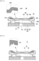
- Fig. 5 is a cross-sectional view of an upper part of a secondary battery according to an embodiment of the present disclosure. Particularly, Fig. 5 is a cross-sectional view which shows the upper part of the cross-section taken along the xz plane after respective components of the secondary battery of Fig. 3 are assembled.
- the secondary battery 100 includes an electrode assembly 200; a battery case 300 that houses the electrode assembly 200 and has an opened upper part; and a cap assembly 400 that is coupled to the opened upper part of the battery case 300.
- the electrode assembly 200 may include a first electrode 210, a second electrode 220, and a separator 230.
- the first electrode 210, the second electrode 220, and the separator 230 can be wound together to form the jelly-roll type electrode assembly 200.
- the separator 230 may be interposed between the first electrode 210 and the second electrode 220.
- the first electrode 210 can be formed by applying an electrode active material onto the first electrode current collector. Meanwhile, to a portion where the electrode active material is not applied among the first electrode current collector and thus the first electrode current collector is exposed, a first electrode tab 213 can be attached by a method such as welding.
- the second electrode 220 can be formed by applying an electrode active material onto the second electrode current collector. Meanwhile, to a portion where the electrode active material is not applied among the second electrode current collector and thus the second electrode current collector is exposed, a second electrode tab 223 can be attached by a method such as welding.
- the first electrode 210 may be a cathode
- the second electrode 220 may be an anode
- the first electrode tab 213 may be a cathode electrode tab
- the second electrode tab 223 may be an anode electrode tab
- the first electrode tab 213 and the second electrode tab 223 may be protruded in mutually opposite directions with respect to the wound electrode assembly 200.
- the first electrode tab 213 may be protruded in a direction (z-axis direction) in which the cap assembly 400 is located
- the second electrode tab 223 may be protruded in a direction (-z-axis direction) in which the bottom part of the battery case 300 is located.
- the battery case 300 is a structure that houses the electrode assembly 200 impregnated with an electrolyte solution, which may include a metal material and may be a cylindrical case.
- the cap assembly 400 includes a safety vent 410 in which a notch portion 410N is formed. More specifically, the cap assembly 400 may include a safety vent 410 and a current interrupt device (CID) located below the safety vent 410.
- CID current interrupt device
- the cap assembly 400 has a structure in which the upper end cap is removed, wherein the safety vent 410 may be exposed to the outside from the upper end.
- the safety vent 410 is located on the current interrupt device 420 and may be electrically connected to the current interrupt device 420. Specifically, the central portion of the safety vent 410 and the first portion 421 of the current interrupt device 420 described later may be physically and electrically connected. A first electrode tab 213 protruding from the first electrode 210 may be connected to a lower end part of the current interrupt device 420.
- the safety vent 410 is a thin structure through which electric current passes, and may be a disk-shaped plate.
- the notch portion 410N formed in the safety vent 410 may have a shape in which a recessed groove extends along a circle.
- the safety vent 410, the current interrupt device 420, and the first electrode tab 213 are sequentially connected, so that the safety vent 410 can function as an electrode terminal that guides the electrical connection of the electrode assembly 200.
- the current interrupt device 420 is a plate member through which electric current passes, and may be formed with through-holes 420H for discharging gas. Further, the current interrupt device 420 may include a first portion 421 connected to the safety vent 410 and a second portion 422 connected to the first electrode tab 213, wherein the first portion 421 may be located at a central portion of the current interrupt device 420, and the second portion 422 may be located at an outer peripheral portion of the current interrupt device 420.
- the shape of the safety vent 410 may be reversed. According to the shape reversal of the safety vent 410, the first portion 421 of the current interrupt device 420 is raised together, so that the first portion 421 and the second portion 422 of the current interrupt device 420 can be separated from each other. In order to induce this separation due to the increase in internal pressure, the space between the first portion 421 and the second portion 422 can be designed to have a slightly weak strength. Due to the separation of the first portion 421 and the second portion 422, a current between the safety vent 410 and the first electrode tab 213 functioning as an electrode terminal is interrupted.
- the safety vent 410 when the internal pressure rises, the notch portion 410N of the safety vent 410 is cut or torn, the safety vent 410 is opened, and internal gas is discharged.
- the upper end cap 41 In the case of a conventional cylindrical secondary battery 10 (see Fig. 1 ), the upper end cap 41 is located on the safety vent 42, so that a spatial portion is degraded and the safety vent 42 may not be fully opened. Thus, the gas cannot be effectively discharged. Further, the upper end cap 41 itself may interfere with gas discharge.
- the safety vent 410 since the safety vent 410 is exposed to the outside from the upper end without an upper end cap, the shape of the safety vent 410 can be freely reversed or separated when the internal pressure rises. Therefore, it is more effective for gas discharge as compared with the conventional cylindrical secondary battery 10.
- Fig. 6 is a cross-sectional view of an upper part of a secondary battery according to a comparative example of the present disclosure.
- the secondary battery 10' according to this comparative example includes a cap assembly 40', wherein the cap assembly 40' includes a safety vent 41' and a current interrupt device 42'.
- a notch portion 41N for gas discharge may be formed in the safety vent 41', wherein the notch portion 41N may form an opened structure while a gap is widened.
- an electrode lead or the like can be joined to the safety vent 41'.
- the electrode lead can be attached to the safety vent 41' using vibration, but in the case of the method using vibration, vibration resistance may be lowered due to the opened notch portion 41N, which may limit the electrode lead attachment process.
- the notch portion 41N does not withstand the applied vibration, which may cause a problem of being cut or tore. If the depth of the notch portion 41N is set to be shallow to improve this, the notch portion 41N does not rather break when the internal pressure rises, which may cause a problem that the safety vent 410 does not operate properly.
- the gap formed by the notch portion 410N according to the present embodiment is closed.
- the gap of the notch portion 410N is expressed to be slightly widened, but this is for convenience of explanation, and the notch portion 410N according to the present embodiment may have a closed structure so that both portions with a gap interposed therebetween are in contact with each other. Since the notch portion 410N forms a closed structure in this way, vibration resistance and structural rigidity are improved. Therefore, even when vibration is applied to the safety vent 410 to attach the electrode lead, the electrode lead may be attached without damaging the safety vent 410.
- the notch portion 410N is cut when the internal pressure rises, so that separation of the safety vent 410 can be performed normally. That is, when the internal pressure rises, the discharge of gas may be smoothly performed.
- the battery case 300 may include a crimping portion 300C and a beading portion 300B.
- the beading portion 300B refers to a portion in which a part of the cylindrical battery case 300 is recessed in the center direction of the electrode assembly 200, which is for stable coupling of the cap assembly 400 and preventing flow of the electrode assembly 200.
- the crimping portion 300C is located above the beading portion 300B and refers to a portion that wraps the cap assembly 400. One end of the upper part of the battery case 300 can be bent to wrap the cap assembly 400 and form a crimping portion 300C.
- a sealing gasket 700 may be mounted on inner surfaces of the crimping portion 300C and the beading portion 300B to increase a sealing force between the cap assembly 400 and the battery case 300. That is, the gasket 700 is located between the battery case 300 and the cap assembly 400, and one end of the upper end of the battery case 300 may be bent to form a crimping joint, so that the crimping portion 300C can be formed. Thereby, mounding of the cap assembly 400 and sealing of the secondary battery 100 can be performed. The gasket 700 may be located between the crimping portion 300C and the safety vent 410.
- a bent portion 410B may be formed in the safety vent 410 according to the present embodiment. Specifically, as shown in Fig. 5 , a part of the safety vent 410 can be bent in an upward direction to form a bent portion 410B. Such a bent portion 410B is formed, so that the deformation transferred to the safety vent 410 during crimp joining can be reduced. Further, as described above, as the shape of the safety vent 410 is reversed in an abnormal operating state, the first portion 421 of the current interrupt device 420 rises together, and the first portion 421 and the second portion 422 of the current interrupt device 420 are separated from each other.
- the flow of current is interrupted, and it is preferable that a certain amount of gap is formed between the safety vent 410 and the current interrupt device 420 for effective current interruption. Therefore, the bent portion 410B bent in an upward direction can be formed to increase the distance between the safety vent 410 and the current interrupt device 420 while minimizing the height of the cap assembly 400 itself.
- the strong physical compression may be applied to the cap assembly 400, which may cause a problem that the cap assembly 400 is damaged.
- the safety vent 410 is damaged in a structure in which the safety vent 410 is exposed without an upper end cap. Even so, if the safety vent 410 is formed thicker than before in order to supplement the rigidity of the safety vent 410, there is a high possibility that the shape reversal or separation of the safety vent 410 will not be realized correctly when the internal pressure rises.
- a curling portion 410C can be provided in a portion corresponding to the crimping portion 300C among the safety vent 410, instead of simply increasing the thickness of the safety vent 410.
- the safety vent 410 may include a curling portion 410C bent at an outer peripheral portion of the safety vent 410.
- Figs. 3 and 4 show a state of the flange part 410F before the curling portion 410C is formed
- Fig. 5 shows a state in which the flange portion 410F is bent to form the curling portion 410C.
- the crimping portion 300C of the battery case 300 may wrap the safety vent 410 with the gasket 700 interposed therebetween.
- a crimping joint may be formed around the curling portion 410C of the safety vent 410. Therefore, the central portion of the safety vent 410 provided with the notch portion 410N is made of one layer, but the outer peripheral portion of the safety vent 410 wrapped around the crimping portion 300C may be formed of two layers. That is, by providing the curling portion 410C, damage to the safety vent 410 that may occur during crimping is prevented and at the same time, it does not interfere with the shape reversal or separation of the safety vent 410 when the internal pressure rises.
- Figs. 7a to 7c are schematic diagrams for explaining a method for manufacturing a secondary battery according to an embodiment of the present disclosure.
- a method for manufacturing a secondary battery includes a step of manufacturing a safety vent 410; a step of manufacturing a cap assembly 400 including the safety vent 410; a step of housing the electrode assembly 200 in a battery case 300 having an opened upper part; and a step of joining the cap assembly 400 to the opened upper part of the battery case 300.
- the step of manufacturing the safety vent 410 includes a step of forming a notch portion 410N on one surface of the metal plate material; and a step of closing the gap formed by the notch portion 410N.
- the metal plate material is a member for forming the safety vent 410, and may be a disk-shaped plate. As shown in Fig. 7a , the outer peripheral portion of the metal plate material can be bent upward to form a flange portion 410F. Next, as shown in Fig. 7b , a notch portion 410N may be formed on one surface of the metal plate material.
- the notch portion 410N formed in the safety vent 410 may have a shape in which a recessed groove extends along a circle. Meanwhile, in Fig.
- notch portion 410N is formed on the lower surface of the metal plate material, but a notch portion 410N may be formed in the upward direction of the flange portion 410F, that is, on the upper surface of the metal plate material.
- the step of bending the metal plate material in an upward direction to form a bent portion 410B and closing a gap formed by the notch portion 410N can be performed. That is, a closed structure may be formed such that gaps formed by the notch portion 410N come into contact with each other together with the formation of the bent portion 410B.
- a forging step may be performed in the step of closing the gap of the notch portion 410N. That is, in the step of closing the gap of the notch portion 410N, a forging step may be performed on both portions P1 and P2 with a gap interposed therebetween. The forging step is to reduce the thickness of the area near the notch 410N. When the thickness of both portions P1 and P2 with a gap interposed therebetween is made thin, the corresponding portion is naturally pushed to the side, and the gap formed by the notch portion 410N can be closed.
- Figs. 8a to 8c are schematic diagrams for explaining a method for manufacturing a secondary battery according to a comparative example of the present disclosure.
- the outer peripheral portion of the metal plate material can be bent upward to form a flange portion 41F.
- the step of bending the metal plate material to produce a bent portion 41B can be performed.
- a notch portion 41N may be formed on one surface of the metal plate material.
- the bent portion 41B and the notch portion 41N are formed in the metal plate material, but the forging step of closing the gap of the notch portion 41N is not performed.
- a forging step may be additionally performed.
- the bent portion 410B By adding a forging step to the step of forming the bent portion 410B, the bent portion 410B can be formed, and the gap formed by the notched portion 410N can be closed. That is, the notch portion 41N having an open structure as shown in Fig. 6 may be manufactured by the method of manufacturing a secondary battery according to the present comparative example, and the notch portion 410N having a closed structure as shown in Fig. 5 can be manufactured by the method of manufacturing the secondary battery according to the present embodiment.
- the flange portion 410F (see Figs. 4 and 7a ) can be bent to form a curling portion 410C (see Fig. 5 ).
- Fig. 9 is a cross-sectional view which shows a state in which a crimping portion is formed according to an embodiment of the present disclosure.
- the safety vent 410 and the current interrupt device 420 manufactured by the above process can be joined to each other to manufacture a cap assembly 400.
- the electrode assembly 200 and the electrolyte solution are housed in a battery case 300, and then the cap assembly 400 may be coupled to the opened upper part of the battery case 300.
- the cap assembly 400 according to the present embodiment has a structure in which the upper end cap is removed, and the safety vent 410 may be exposed to the outside from the upper end.
- the upper end 300U of the battery case 300 can be bent to form a crimping joint and form a crimping portion 300C (see Fig. 5 ) for covering the cap assembly 400.
- a gasket 700 for sealing may be positioned between the cap assembly 400 and the battery case 300.
- the secondary battery 100 having a safety vent 410 including a notch portion 410N having a closed structure and a curling portion 410C located on the outer periphery.
- a plurality of secondary batteries described above may be gathered to form a battery module.
- the battery modules may be mounted together with various control and protection systems such as BDU(battery disconnect unit), BMS (battery management system) and a cooling system to form a battery pack.
- BDU battery disconnect unit
- BMS battery management system
- cooling system to form a battery pack.
- the above-mentioned secondary battery, the batter module and the battery pack can be applied to various devices.
- a device can be applied to a vehicle means such as an electric bicycle, an electric vehicle, or a hybrid vehicle, but the present disclosure is not limited thereto, and is applicable to various devices that can use a secondary battery.
Landscapes
- Chemical & Material Sciences (AREA)
- Chemical Kinetics & Catalysis (AREA)
- Electrochemistry (AREA)
- General Chemical & Material Sciences (AREA)
- Engineering & Computer Science (AREA)
- Materials Engineering (AREA)
- Manufacturing & Machinery (AREA)
- Gas Exhaust Devices For Batteries (AREA)
- Sealing Battery Cases Or Jackets (AREA)
- Connection Of Batteries Or Terminals (AREA)
Abstract
Description
- This application claims the benefit of
Korean Patent Application No. 10-2020-0183516 filed on December 24, 2020 - The present disclosure relates to a secondary battery and a method for manufacturing the same, and more particularly, to a secondary battery with improved vibration resistance and a method for manufacturing the same.
- Recently, as energy source price is increasing due to the depletion of fossil fuels and increasing interest is being paid to environmental pollution, the demand for environmentally-friendly alternative energy sources is bound to play an important role in the future life. Thus, research into techniques for generating various kinds of power, such as nuclear energy, solar energy, wind energy, and tidal power, is underway, and power storage apparatuses for more efficient use of the generated energy are also drawing much attention.
- In particular, along with the technology development and increased demand for mobile devices, demand for batteries as energy sources has been increasing rapidly, and accordingly, much research on batteries which can meet the various needs has been carried out.
- Typically, the demand for the lithium secondary battery, such as a lithium ion battery or a lithium ion polymer battery, which have advantages such as a high energy density, a discharge voltage, an output stability, and the like is high.
- Further, the secondary battery may be classified based on the structure of an electrode assembly having a structure in which a cathode and an anode are stacked with a separator being interposed therebetween. Typically, there may mentioned, for example, a jelly-roll type electrode assembly having a structure in which long sheets of cathodes and anodes are wound in the state in which a separator is interposed therebetween, a stacked type electrode assembly having a structure in which pluralities of cathodes and anodes, cut by a certain size unit, are sequentially stacked in the state in which separators are interposed therebetween, or the like. In recent years, in order to solve problems caused by the jelly-roll type electrode assembly and the stacked type electrode assembly, there has been developed a stacked/folded type electrode assembly, which is a combination of the jelly-roll type electrode assembly and the stacked type electrode assembly, having a structure in which unit cells stacked with predetermined units of the cathodes and the anodes are sequentially wound with a separator being interposed therebetween in the state of having been placed on a separation film.
- Further, based on the shape of a battery case, the secondary battery is classified into a cylindrical battery where an electrode assembly is mounted in a cylindrical case, a prismatic battery where an electrode assembly is mounted in a prismatic can, and a pouch type battery where an electrode assembly is mounted in a pouch type case of an aluminum laminate sheet.
- Meanwhile, a secondary battery can be suitably used in the market as long as it satisfies performance suitable for the intended use and at the same time, has safety. When designing a secondary battery, the design factors are determined in consideration of these performance and safety aspects at the same time. Batteries whose design and manufacturing are completed are subjected to performance evaluations such as lifespan, high rate characteristics, and high/low temperature characteristics, as well as to safety evaluations such as overcharge, over-discharge, impact, nail test, and hot box.
- Among the various types of secondary batteries, a cylindrical secondary battery may include a current interrupt device (CID) that interrupts the current between the electrode terminal and the electrode tab to prevent additional reactions, when gas is suddenly generated inside the secondary battery in an abnormal state such as overcharge and the internal pressure exceeds a certain level.
-
Fig. 1 is a partial cross-sectional view which shows a cross-section of the upper part of a conventional cylindrical secondary battery. - Referring to
Fig. 1 , a cylindricalsecondary battery 10 can be manufactured by housing anelectrode assembly 20 in acylindrical case 30, and mounting acap assembly 40 onto the opened upper part of thecylindrical case 30. - The
electrode assembly 20 may be a jelly-roll type electrode assembly in which afirst electrode 21, asecond electrode 22, and aseparator 23 are wound. - The
cap assembly 40 may include anupper end cap 41, an internal pressuredrop safety vent 42 and a current interrupt device (CID) 43. Theupper end cap 41 and thesafety vent 42 can form a structure in close contact with each other, and thesafety vent 42 can be connected to the central part of thecurrent interrupt device 43. Afirst electrode tab 21t protruding from thefirst electrode 21 can be connected to the lower end part of thecurrent interrupt device 43. Here, thefirst electrode 21 may be a cathode, and thefirst electrode tab 21t may be a cathode tab. - As described above, the
upper end cap 41 can be directly or indirectly connected to thesafety vent 42, thecurrent interrupt device 43 and thefirst electrode tabs 21t to be electrically connected to theelectrode assembly 20, and can function as an electrode terminal. - Meanwhile, a
gasket 70 for sealing between thecap assembly 40 and thecylindrical case 30 and aCID gasket 80 for wrapping the edge of thecurrent interrupt device 43 may be arranged. -
Fig. 2 is a partial cross-sectional view which shows a state when the internal pressure of the cylindrical secondary battery ofFig. 1 is increased. - Referring to
Fig. 2 , when the cylindricalsecondary battery 10 is exposed to high temperature or is placed in an abnormal operating state to increase the internal pressure, the shape of thesafety vent 42 is reversed, and thecurrent interrupt device 43 is separated to interrupt the current. Specifically, thecurrent interrupt device 43 is divided into aportion 43a connected to thesafety vent 42 and aportion 43b connected to thefirst electrode tab 21t, so that the flow of current between theupper end cap 41 and thefirst electrode tab 21 functioning as an electrode terminal is interrupted. Further, if the internal pressure is increased significantly, the notch portion of thesafety vent 42 is cut, thesafety vent 42 is opened, and the internal gas is discharged. - When the
upper end cap 41 is provided as in the conventional cylindricalsecondary battery 10, the structural rigidity is excellent, but when the internal gas is discharged while thesafety vent 42 is opened, there is a drawback in that a spatial portion is degraded by theupper cap 41 and thus, thesafety vent 42 cannot be fully opened and the gas discharge is restricted. - It is an object of the present disclosure to provide a secondary battery having vibration resistance and structural rigidity while effectively providing an internal gas discharge path, and a method for manufacturing the same.
- However, the problem to be solved by the embodiments of the present disclosure is not limited to the above-described problems, and can be variously expanded within the scope of the technical idea included in the present disclosure.
- According to one embodiment of the present disclosure, there is provided a secondary battery comprising: an electrode assembly; a battery case that houses the electrode assembly and has an opened upper part; and a cap assembly that is coupled to the opened upper part of the battery case, wherein the cap assembly comprises a safety vent formed with a notch portion, and wherein a gap formed by the notch portion is closed.
- The safety vent may be exposed to the outside from the upper end.
- The safety vent may be a disk-shaped plate, and the notch portion may have a shape in which a recessed groove extends along a circle.
- One end of the upper part of the battery case may be bent to wrap the cap assembly and form a crimping portion.
- The crimping portion of the battery case may wrap the safety vent.
- The safety vent may include a curling portion bent at the outer peripheral part of the safety vent, and the crimping portion may wrap the curling portion to form a crimping joint.
- The safety vent may be formed with a bent portion bent in an upward direction.
- According to another embodiment of the present disclosure, there is provided a method for manufacturing a secondary battery, the method comprising the steps of: manufacturing a safety vent; manufacturing a cap assembly including the safety vent; housing the electrode assembly in a battery case having an opened upper part; and joining the cap assembly to the opened upper part of the battery case, wherein the step of manufacturing the safety vent comprises forming a notch portion on one surface of a metal plate material; and closing the gap formed by the notch portion.
- The safety vent may be exposed to the outside from the upper end.
- The safety vent may be a disk-shaped plate, and the notch portion may have a shape in which a recessed groove extends along a circle.
- The step of joining the cap assembly may include a step of bending one end of the upper part of the battery case to form a crimping portion that wraps the cap assembly, the step of manufacturing the safety vent may include a step of bending the flange part formed on the metal plate material to form a curling portion, and in the step of forming the crimping portion, the crimping portion may wrap the curling portion.
- In the step of closing the gap formed by the notch portion, a forging step may be performed on both portions with a gap interposed therebetween.
- According to the embodiments of the present disclosure, the upper end cap is removed and the safety vent is exposed to the outside, so that the spatial restriction on the safety vent is eliminated, whereby when the internal pressure rises, the safety vent can be fully opened, which can be effective in discharging gas.
- Additionally, the notch portion of the safety vent is provided in a closed structure, whereby when the lead is attached to the safety vent, vibration resistance and structural rigidity of the notch portion can be increased.
- The effects of the present disclosure are not limited to the effects mentioned above and additional other effects not described above will be clearly understood from the description of the appended claims by those skilled in the art.
-
-
Fig. 1 is a partial cross-sectional view which shows a cross-section of the upper part of a conventional cylindrical secondary battery; -
Fig. 2 is a partial cross-sectional view which shows a state when the internal pressure of the cylindrical secondary battery ofFig. 1 is increased; -
Fig. 3 is an exploded perspective view of a secondary battery according to an embodiment of the present disclosure;\ -
Fig. 4 is a cross-sectional perspective view of a safety vent included in the secondary battery ofFig. 3 ; -
Fig. 5 is a cross-sectional view of an upper part of a secondary battery according to an embodiment of the present disclosure; -
Fig. 6 is a cross-sectional view of an upper part of a secondary battery according to a comparative example of the present disclosure; -
Figs. 7a to 7c are schematic diagrams for explaining a method for manufacturing a secondary battery according to an embodiment of the present disclosure; -
Figs. 8a to 8c are schematic diagrams for explaining a method for manufacturing a secondary battery according to a comparative example of the present disclosure; and -
Fig. 9 is a cross-sectional view that shows the appearance of forming a crimping portion according to an embodiment of the present disclosure. - Hereinafter, various embodiments of the present disclosure will be described in detail with reference to the accompanying drawings so that those skilled in the art can easily carry out them. The present disclosure can be modified in various different ways, and is not limited to the embodiments set forth herein.
- Portions that are irrelevant to the description will be omitted to clearly describe the present disclosure, and like reference numerals designate like elements throughout the description.
- Further, in the drawings, the size and thickness of each element are arbitrarily illustrated for convenience of description, and the present disclosure is not necessarily limited to those illustrated in the drawings. In the drawings, the thickness of layers, regions, etc. are exaggerated for clarity. In the drawings, for convenience of description, the thicknesses of some layers and regions are exaggerated.
- In addition, it will be understood that when an element such as a layer, film, region, or plate is referred to as being "on" or "above" another element, it can be directly on the other element or intervening elements may also be present. In contrast, when an element is referred to as being "directly on" another element, it means that other intervening elements are not present. Further, the word "on" or "above" means disposed on or below a reference portion, and does not necessarily mean being disposed on the upper end of the reference portion toward the opposite direction of gravity.
- Further, throughout the description, when a portion is referred to as "including" or "comprising" a certain component, it means that the portion can further include other components, without excluding the other components, unless otherwise stated.
- Further, throughout the description, when referred to as "planar", it means when a target portion is viewed from the upper side, and when referred to as "cross-sectional", it means when a target portion is viewed from the side of a cross section cut vertically.
-
Fig. 3 is an exploded perspective view of a secondary battery according to an embodiment of the present disclosure.Fig. 4 is a cross-sectional perspective view of a safety vent included in the secondary battery ofFig. 3 .Fig. 5 is a cross-sectional view of an upper part of a secondary battery according to an embodiment of the present disclosure. Particularly,Fig. 5 is a cross-sectional view which shows the upper part of the cross-section taken along the xz plane after respective components of the secondary battery ofFig. 3 are assembled. - Referring to
Figs. 3 to 5 , thesecondary battery 100 according to an embodiment of the present disclosure includes anelectrode assembly 200; abattery case 300 that houses theelectrode assembly 200 and has an opened upper part; and acap assembly 400 that is coupled to the opened upper part of thebattery case 300. - First, the
electrode assembly 200 according to the present embodiment may include afirst electrode 210, asecond electrode 220, and aseparator 230. Thefirst electrode 210, thesecond electrode 220, and theseparator 230 can be wound together to form the jelly-rolltype electrode assembly 200. Theseparator 230 may be interposed between thefirst electrode 210 and thesecond electrode 220. - Although not specifically illustrated, the
first electrode 210 can be formed by applying an electrode active material onto the first electrode current collector. Meanwhile, to a portion where the electrode active material is not applied among the first electrode current collector and thus the first electrode current collector is exposed, afirst electrode tab 213 can be attached by a method such as welding. - The
second electrode 220 can be formed by applying an electrode active material onto the second electrode current collector. Meanwhile, to a portion where the electrode active material is not applied among the second electrode current collector and thus the second electrode current collector is exposed, asecond electrode tab 223 can be attached by a method such as welding. - At this time, the
first electrode 210 may be a cathode, and thesecond electrode 220 may be an anode. Thereby, thefirst electrode tab 213 may be a cathode electrode tab, and thesecond electrode tab 223 may be an anode electrode tab. Meanwhile, thefirst electrode tab 213 and thesecond electrode tab 223 may be protruded in mutually opposite directions with respect to thewound electrode assembly 200. As shown inFig. 3 , thefirst electrode tab 213 may be protruded in a direction (z-axis direction) in which thecap assembly 400 is located, and thesecond electrode tab 223 may be protruded in a direction (-z-axis direction) in which the bottom part of thebattery case 300 is located. - Meanwhile, the
battery case 300 is a structure that houses theelectrode assembly 200 impregnated with an electrolyte solution, which may include a metal material and may be a cylindrical case. - The
cap assembly 400 according to the present embodiment includes asafety vent 410 in which anotch portion 410N is formed. More specifically, thecap assembly 400 may include asafety vent 410 and a current interrupt device (CID) located below thesafety vent 410. - Unlike the conventional cylindrical secondary battery 10 (see
Fig. 1 ), thecap assembly 400 according to the present embodiment has a structure in which the upper end cap is removed, wherein thesafety vent 410 may be exposed to the outside from the upper end. - The
safety vent 410 is located on the current interruptdevice 420 and may be electrically connected to the current interruptdevice 420. Specifically, the central portion of thesafety vent 410 and thefirst portion 421 of the current interruptdevice 420 described later may be physically and electrically connected. Afirst electrode tab 213 protruding from thefirst electrode 210 may be connected to a lower end part of the current interruptdevice 420. - The
safety vent 410 is a thin structure through which electric current passes, and may be a disk-shaped plate. Thenotch portion 410N formed in thesafety vent 410 may have a shape in which a recessed groove extends along a circle. Thesafety vent 410, the current interruptdevice 420, and thefirst electrode tab 213 are sequentially connected, so that thesafety vent 410 can function as an electrode terminal that guides the electrical connection of theelectrode assembly 200. - The current interrupt
device 420 according to the present embodiment is a plate member through which electric current passes, and may be formed with through-holes 420H for discharging gas. Further, the current interruptdevice 420 may include afirst portion 421 connected to thesafety vent 410 and asecond portion 422 connected to thefirst electrode tab 213, wherein thefirst portion 421 may be located at a central portion of the current interruptdevice 420, and thesecond portion 422 may be located at an outer peripheral portion of the current interruptdevice 420. - When the internal pressure of the
secondary battery 100 rises, the shape of thesafety vent 410 may be reversed. According to the shape reversal of thesafety vent 410, thefirst portion 421 of the current interruptdevice 420 is raised together, so that thefirst portion 421 and thesecond portion 422 of the current interruptdevice 420 can be separated from each other. In order to induce this separation due to the increase in internal pressure, the space between thefirst portion 421 and thesecond portion 422 can be designed to have a slightly weak strength. Due to the separation of thefirst portion 421 and thesecond portion 422, a current between thesafety vent 410 and thefirst electrode tab 213 functioning as an electrode terminal is interrupted. - Additionally, when the internal pressure rises, the
notch portion 410N of thesafety vent 410 is cut or torn, thesafety vent 410 is opened, and internal gas is discharged. In the case of a conventional cylindrical secondary battery 10 (seeFig. 1 ), theupper end cap 41 is located on thesafety vent 42, so that a spatial portion is degraded and thesafety vent 42 may not be fully opened. Thus, the gas cannot be effectively discharged. Further, theupper end cap 41 itself may interfere with gas discharge. Unlike the same, in thesecondary battery 100 according to the present embodiment, since thesafety vent 410 is exposed to the outside from the upper end without an upper end cap, the shape of thesafety vent 410 can be freely reversed or separated when the internal pressure rises. Therefore, it is more effective for gas discharge as compared with the conventional cylindricalsecondary battery 10. - Next, the advantages that the
safety vent 410 according to the present embodiment has over the safety vent 41'according to the comparative example of the present disclosure will be described with reference toFigs. 5 and 6 . -
Fig. 6 is a cross-sectional view of an upper part of a secondary battery according to a comparative example of the present disclosure. Referring toFig. 6 , the secondary battery 10' according to this comparative example includes a cap assembly 40', wherein the cap assembly 40' includes a safety vent 41' and a current interrupt device 42'. At this time, anotch portion 41N for gas discharge may be formed in the safety vent 41', wherein thenotch portion 41N may form an opened structure while a gap is widened. - When the upper end cap is removed and the safety vent 41' is exposed to the outside from the upper end and functions as an electrode terminal, an electrode lead or the like can be joined to the safety vent 41'. At this time, the electrode lead can be attached to the safety vent 41' using vibration, but in the case of the method using vibration, vibration resistance may be lowered due to the opened
notch portion 41N, which may limit the electrode lead attachment process. In other words, thenotch portion 41N does not withstand the applied vibration, which may cause a problem of being cut or tore. If the depth of thenotch portion 41N is set to be shallow to improve this, thenotch portion 41N does not rather break when the internal pressure rises, which may cause a problem that thesafety vent 410 does not operate properly. - Unlike the opened
notch portion 41N in the comparative example, referring toFigs. 4 and5 , the gap formed by thenotch portion 410N according to the present embodiment is closed. InFigs. 4 and5 , in order to explain the groove structure, the gap of thenotch portion 410N is expressed to be slightly widened, but this is for convenience of explanation, and thenotch portion 410N according to the present embodiment may have a closed structure so that both portions with a gap interposed therebetween are in contact with each other. Since thenotch portion 410N forms a closed structure in this way, vibration resistance and structural rigidity are improved. Therefore, even when vibration is applied to thesafety vent 410 to attach the electrode lead, the electrode lead may be attached without damaging thesafety vent 410. At the same time, since the depth of the recessed groove structure in thenotch portion 410N is maintained as it is, thenotch portion 410N is cut when the internal pressure rises, so that separation of thesafety vent 410 can be performed normally. That is, when the internal pressure rises, the discharge of gas may be smoothly performed. - Meanwhile, referring to
Fig. 5 again, thebattery case 300 according to the present embodiment may include a crimpingportion 300C and abeading portion 300B. Thebeading portion 300B refers to a portion in which a part of thecylindrical battery case 300 is recessed in the center direction of theelectrode assembly 200, which is for stable coupling of thecap assembly 400 and preventing flow of theelectrode assembly 200. The crimpingportion 300C is located above thebeading portion 300B and refers to a portion that wraps thecap assembly 400. One end of the upper part of thebattery case 300 can be bent to wrap thecap assembly 400 and form a crimpingportion 300C. - A sealing
gasket 700 may be mounted on inner surfaces of the crimpingportion 300C and thebeading portion 300B to increase a sealing force between thecap assembly 400 and thebattery case 300. That is, thegasket 700 is located between thebattery case 300 and thecap assembly 400, and one end of the upper end of thebattery case 300 may be bent to form a crimping joint, so that the crimpingportion 300C can be formed. Thereby, mounding of thecap assembly 400 and sealing of thesecondary battery 100 can be performed. Thegasket 700 may be located between the crimpingportion 300C and thesafety vent 410. - Meanwhile, a
bent portion 410B may be formed in thesafety vent 410 according to the present embodiment. Specifically, as shown inFig. 5 , a part of thesafety vent 410 can be bent in an upward direction to form abent portion 410B. Such abent portion 410B is formed, so that the deformation transferred to thesafety vent 410 during crimp joining can be reduced. Further, as described above, as the shape of thesafety vent 410 is reversed in an abnormal operating state, thefirst portion 421 of the current interruptdevice 420 rises together, and thefirst portion 421 and thesecond portion 422 of the current interruptdevice 420 are separated from each other. Thereby, the flow of current is interrupted, and it is preferable that a certain amount of gap is formed between thesafety vent 410 and the current interruptdevice 420 for effective current interruption. Therefore, thebent portion 410B bent in an upward direction can be formed to increase the distance between thesafety vent 410 and the current interruptdevice 420 while minimizing the height of thecap assembly 400 itself. - Meanwhile, in the case of crimp joining, the strong physical compression may be applied to the
cap assembly 400, which may cause a problem that thecap assembly 400 is damaged. In particular, as in the present embodiment, there is a risk that thesafety vent 410 is damaged in a structure in which thesafety vent 410 is exposed without an upper end cap. Even so, if thesafety vent 410 is formed thicker than before in order to supplement the rigidity of thesafety vent 410, there is a high possibility that the shape reversal or separation of thesafety vent 410 will not be realized correctly when the internal pressure rises. - In the cap assembly according to the present embodiment, a curling
portion 410C can be provided in a portion corresponding to the crimpingportion 300C among thesafety vent 410, instead of simply increasing the thickness of thesafety vent 410. Specifically, thesafety vent 410 may include a curlingportion 410C bent at an outer peripheral portion of thesafety vent 410. For convenience of explanation,Figs. 3 and4 show a state of theflange part 410F before the curlingportion 410C is formed, andFig. 5 shows a state in which theflange portion 410F is bent to form the curlingportion 410C. - The crimping
portion 300C of thebattery case 300 may wrap thesafety vent 410 with thegasket 700 interposed therebetween. Among them, a crimping joint may be formed around the curlingportion 410C of thesafety vent 410. Therefore, the central portion of thesafety vent 410 provided with thenotch portion 410N is made of one layer, but the outer peripheral portion of thesafety vent 410 wrapped around the crimpingportion 300C may be formed of two layers. That is, by providing the curlingportion 410C, damage to thesafety vent 410 that may occur during crimping is prevented and at the same time, it does not interfere with the shape reversal or separation of thesafety vent 410 when the internal pressure rises. - Next, a method for manufacturing a secondary battery according to an embodiment of the present disclosure will be described in detail with reference to
Figs. 7a to 7c andFigs. 8a to 8c . However, portions overlapping with the above-mentioned contents will be omitted to avoid repetition of the description. -
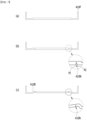
Figs. 7a to 7c are schematic diagrams for explaining a method for manufacturing a secondary battery according to an embodiment of the present disclosure. - Referring to
Figs. 3 ,5 and7a to 7c , a method for manufacturing a secondary battery includes a step of manufacturing asafety vent 410; a step of manufacturing acap assembly 400 including thesafety vent 410; a step of housing theelectrode assembly 200 in abattery case 300 having an opened upper part; and a step of joining thecap assembly 400 to the opened upper part of thebattery case 300. The step of manufacturing thesafety vent 410 includes a step of forming anotch portion 410N on one surface of the metal plate material; and a step of closing the gap formed by thenotch portion 410N. - Specifically, the metal plate material is a member for forming the
safety vent 410, and may be a disk-shaped plate. As shown inFig. 7a , the outer peripheral portion of the metal plate material can be bent upward to form aflange portion 410F. Next, as shown inFig. 7b , anotch portion 410N may be formed on one surface of the metal plate material. Thenotch portion 410N formed in thesafety vent 410 may have a shape in which a recessed groove extends along a circle. Meanwhile, inFig. 7b , it is shown that thenotch portion 410N is formed on the lower surface of the metal plate material, but anotch portion 410N may be formed in the upward direction of theflange portion 410F, that is, on the upper surface of the metal plate material. - Next, as shown in
Fig. 7c , the step of bending the metal plate material in an upward direction to form abent portion 410B and closing a gap formed by thenotch portion 410N can be performed. That is, a closed structure may be formed such that gaps formed by thenotch portion 410N come into contact with each other together with the formation of thebent portion 410B. - In more detail, in the step of closing the gap of the
notch portion 410N, a forging step may be performed. That is, in the step of closing the gap of thenotch portion 410N, a forging step may be performed on both portions P1 and P2 with a gap interposed therebetween. The forging step is to reduce the thickness of the area near thenotch 410N. When the thickness of both portions P1 and P2 with a gap interposed therebetween is made thin, the corresponding portion is naturally pushed to the side, and the gap formed by thenotch portion 410N can be closed. - Meanwhile,
Figs. 8a to 8c are schematic diagrams for explaining a method for manufacturing a secondary battery according to a comparative example of the present disclosure. - First, referring to
Fig. 8a , the outer peripheral portion of the metal plate material can be bent upward to form aflange portion 41F. Next, as shown inFig. 8b , the step of bending the metal plate material to produce abent portion 41B can be performed. Next, as shown inFig. 8C , anotch portion 41N may be formed on one surface of the metal plate material. In this comparative example, thebent portion 41B and thenotch portion 41N are formed in the metal plate material, but the forging step of closing the gap of thenotch portion 41N is not performed. Meanwhile, in the present embodiment, when thebent portion 410B is formed on the metal plate material after forming thenotch portion 410N, a forging step may be additionally performed. By adding a forging step to the step of forming thebent portion 410B, thebent portion 410B can be formed, and the gap formed by the notchedportion 410N can be closed. That is, thenotch portion 41N having an open structure as shown inFig. 6 may be manufactured by the method of manufacturing a secondary battery according to the present comparative example, and thenotch portion 410N having a closed structure as shown inFig. 5 can be manufactured by the method of manufacturing the secondary battery according to the present embodiment. - After that, in the step of manufacturing the
safety vent 410, theflange portion 410F (seeFigs. 4 and7a ) can be bent to form a curlingportion 410C (seeFig. 5 ). - Meanwhile,
Fig. 9 is a cross-sectional view which shows a state in which a crimping portion is formed according to an embodiment of the present disclosure. - Referring to
Figs. 3 and9 , thesafety vent 410 and the current interruptdevice 420 manufactured by the above process can be joined to each other to manufacture acap assembly 400. Theelectrode assembly 200 and the electrolyte solution are housed in abattery case 300, and then thecap assembly 400 may be coupled to the opened upper part of thebattery case 300. As described above, thecap assembly 400 according to the present embodiment has a structure in which the upper end cap is removed, and thesafety vent 410 may be exposed to the outside from the upper end. - Specifically, the
upper end 300U of thebattery case 300 can be bent to form a crimping joint and form a crimpingportion 300C (seeFig. 5 ) for covering thecap assembly 400. Agasket 700 for sealing may be positioned between thecap assembly 400 and thebattery case 300. - Through such a manufacturing method, it is possible to manufacture the
secondary battery 100 having asafety vent 410 including anotch portion 410N having a closed structure and a curlingportion 410C located on the outer periphery. - Although the terms representing directions such as front, rear, left, right, upper and lower directions are used herein, it would be obvious to those skilled in the art that these merely represent for convenience of explanation, and may differ depending on a position of an object, a position of an observer, or the like.
- A plurality of secondary batteries described above may be gathered to form a battery module. The battery modules may be mounted together with various control and protection systems such as BDU(battery disconnect unit), BMS (battery management system) and a cooling system to form a battery pack.
- The above-mentioned secondary battery, the batter module and the battery pack can be applied to various devices. Such a device can be applied to a vehicle means such as an electric bicycle, an electric vehicle, or a hybrid vehicle, but the present disclosure is not limited thereto, and is applicable to various devices that can use a secondary battery.
- Although preferred embodiments of the present disclosure have been described in detail above, the scope of the present disclosure is not limited thereto, and various modifications and improvements made by those skilled in the art using the basic concepts of the present disclosure, which are defined in the appended claims, also belong to the scope of the present disclosure.
-
- 100: secondary battery
- 400: electrode assembly
- 410: safety vent
- 410N: notch portion
- 410C: curling portion
Claims (12)
- A secondary battery comprising:an electrode assembly;a battery case that houses the electrode assembly and has an opened upper part; anda cap assembly that is coupled to the opened upper part of the battery case,wherein the cap assembly comprises a safety vent formed with a notch portion, andwherein a gap formed by the notch portion is closed.
- The secondary battery of claim 1, wherein:
the safety vent is exposed to the outside from the upper end. - The secondary battery of claim 1, wherein:the safety vent is a disk-shaped plate, andthe notch portion has a shape in which a recessed groove extends along a circle.
- The secondary battery of claim 1, wherein:
one end of the upper part of the battery case is bent to wrap the cap assembly and form a crimping portion. - The secondary battery of claim 4, wherein:
the crimping portion of the battery case wraps the safety vent. - The secondary battery of claim 5, wherein:the safety vent comprises a curling portion bent at the outer peripheral part of the safety vent, andthe crimping portion wraps the curling portion to form a crimping joint.
- The secondary battery of claim 1, wherein:
the safety vent is formed with a bent portion bent in an upward direction. - A method for manufacturing a secondary battery, the method comprising the steps of:manufacturing a safety vent;manufacturing a cap assembly including the safety vent;housing the electrode assembly in a battery case having an opened upper part; andjoining the cap assembly to the opened upper part of the battery case,wherein the step of manufacturing the safety vent comprises,forming a notch portion on one surface of a metal plate material; andclosing the gap formed by the notch portion.
- The method for manufacturing a secondary battery of claim 8, wherein:
the safety vent is exposed to the outside from the upper end. - The method for manufacturing a secondary battery of claim 8, wherein:the safety vent is a disk-shaped plate, andthe notch portion has a shape in which a recessed groove extends along a circle.
- The method for manufacturing a secondary battery of claim 8, wherein:the step of joining the cap assembly comprises bending one end of the upper part of the battery case to form a crimping portion that wraps the cap assembly,the step of manufacturing the safety vent comprises bending the flange part formed on the metal plate material to form a curling portion, andin the step of forming the crimping portion, the crimping portion wraps the curling portion.
- The method for manufacturing a secondary battery of claim 8, wherein:
in the step of closing the gap formed by the notch portion, a forging step is performed on both portions with a gap interposed therebetween.
Priority Applications (1)
| Application Number | Priority Date | Filing Date | Title |
|---|---|---|---|
| EP26161974.6A EP4730551A2 (en) | 2020-12-24 | 2021-11-03 | Secondary battery and manufacturing method of the same |
Applications Claiming Priority (2)
| Application Number | Priority Date | Filing Date | Title |
|---|---|---|---|
| KR1020200183516A KR102821618B1 (en) | 2020-12-24 | 2020-12-24 | Secondary battery and manufacturing method of the same |
| PCT/KR2021/015758 WO2022139163A1 (en) | 2020-12-24 | 2021-11-03 | Secondary battery and manufacturing method for same |
Related Child Applications (2)
| Application Number | Title | Priority Date | Filing Date |
|---|---|---|---|
| EP26161974.6A Division-Into EP4730551A2 (en) | 2020-12-24 | 2021-11-03 | Secondary battery and manufacturing method of the same |
| EP26161974.6A Division EP4730551A2 (en) | 2020-12-24 | 2021-11-03 | Secondary battery and manufacturing method of the same |
Publications (3)
| Publication Number | Publication Date |
|---|---|
| EP4184693A1 true EP4184693A1 (en) | 2023-05-24 |
| EP4184693A4 EP4184693A4 (en) | 2024-11-13 |
| EP4184693B1 EP4184693B1 (en) | 2026-04-22 |
Family
ID=82158143
Family Applications (2)
| Application Number | Title | Priority Date | Filing Date |
|---|---|---|---|
| EP21911230.7A Active EP4184693B1 (en) | 2020-12-24 | 2021-11-03 | Secondary battery and manufacturing method of the same |
| EP26161974.6A Pending EP4730551A2 (en) | 2020-12-24 | 2021-11-03 | Secondary battery and manufacturing method of the same |
Family Applications After (1)
| Application Number | Title | Priority Date | Filing Date |
|---|---|---|---|
| EP26161974.6A Pending EP4730551A2 (en) | 2020-12-24 | 2021-11-03 | Secondary battery and manufacturing method of the same |
Country Status (6)
| Country | Link |
|---|---|
| US (1) | US20230299413A1 (en) |
| EP (2) | EP4184693B1 (en) |
| JP (1) | JP7673999B2 (en) |
| KR (1) | KR102821618B1 (en) |
| CN (1) | CN115917845B (en) |
| WO (1) | WO2022139163A1 (en) |
Families Citing this family (4)
| Publication number | Priority date | Publication date | Assignee | Title |
|---|---|---|---|---|
| WO2024136118A1 (en) * | 2022-12-23 | 2024-06-27 | 주식회사 엘지에너지솔루션 | Battery cell, battery pack, and vehicle comprising same |
| KR20240162376A (en) * | 2023-05-08 | 2024-11-15 | 주식회사 엘지에너지솔루션 | Cylindrical battery cell, and battery pack and vehicle including the same |
| SE548019C2 (en) * | 2023-12-21 | 2026-01-13 | Northvolt Ab | Cylindrical secondary cell |
| SE2330600A1 (en) * | 2023-12-21 | 2025-06-22 | Northvolt Ab | Cylindrical secondary cell |
Family Cites Families (24)
| Publication number | Priority date | Publication date | Assignee | Title |
|---|---|---|---|---|
| JP3511698B2 (en) * | 1994-11-29 | 2004-03-29 | 宇部興産株式会社 | Sealed non-aqueous secondary battery |
| KR100303825B1 (en) * | 1998-07-28 | 2001-11-30 | 김순택 | Secondary Battery Cap Assembly |
| JP2000182587A (en) * | 1998-12-10 | 2000-06-30 | Wako Denshi Kk | Safety valve for battery explosion-proof and method of manufacturing the same |
| JP4155734B2 (en) * | 2001-12-20 | 2008-09-24 | 三洋電機株式会社 | Battery safety valve |
| US7833647B2 (en) * | 2004-04-28 | 2010-11-16 | Eveready Battery Company, Inc. | Closure vent seal and assembly |
| JP2014041932A (en) * | 2012-08-22 | 2014-03-06 | Nisshinbo Holdings Inc | Electricity storage element |
| JP6187895B2 (en) * | 2012-10-18 | 2017-08-30 | 睦月電機株式会社 | Safety valve for sealed electrochemical devices |
| WO2014119308A1 (en) * | 2013-01-31 | 2014-08-07 | 三洋電機株式会社 | Sealed battery |
| JP2014234857A (en) * | 2013-05-31 | 2014-12-15 | 株式会社みかど製作所 | Safety valve for sealed container |
| CN106030855B (en) * | 2014-03-28 | 2019-08-23 | 三洋电机株式会社 | Cylindrical sealed battery and battery pack |
| CN204289578U (en) * | 2014-11-28 | 2015-04-22 | 天津市津品源科技发展有限公司 | The explosion-proof diaphragm of a kind of Novel battery cover |
| KR101850182B1 (en) * | 2015-04-10 | 2018-04-18 | 주식회사 엘지화학 | Cap Assembly Of Cylindrical Type Secondary Battery And Manufacturing Method Thereof |
| CN205542929U (en) * | 2016-04-08 | 2016-08-31 | 江阴市东润电子有限公司 | Novel explosion -proof combined cover cap explosion -proof aluminum sheet of cylinder lithium cell |
| KR102093386B1 (en) * | 2016-06-22 | 2020-03-25 | 주식회사 엘지화학 | Secondary battery and method of interrupting current of the secondary battery |
| KR20180018279A (en) * | 2016-08-11 | 2018-02-21 | 신흥에스이씨주식회사 | Cap assembly of excellent electrical safety for a secondary battery and the battery inclusive of the same |
| WO2018030836A1 (en) * | 2016-08-11 | 2018-02-15 | Shin Heung Energy & Electronic Co.,Ltd. | Cap assembly for secondary battery and secondary battery including the cap assembly |
| KR20180119375A (en) * | 2017-04-25 | 2018-11-02 | 삼성에스디아이 주식회사 | Secondary Battery |
| KR102394496B1 (en) * | 2017-10-12 | 2022-05-04 | 주식회사 엘지에너지솔루션 | The Safety Vent |
| KR102275779B1 (en) * | 2017-11-17 | 2021-07-13 | 주식회사 엘지에너지솔루션 | Secondary battery |
| WO2019117342A1 (en) * | 2017-12-13 | 2019-06-20 | 삼성에스디아이(주) | Secondary battery |
| KR102487217B1 (en) * | 2018-02-01 | 2023-01-11 | 주식회사 엘지에너지솔루션 | Cap Assembly Having Rivet, and Cylindrical Battery Comprising Beading-part free and Climping-part free and the Cap Assembly |
| KR102421803B1 (en) * | 2018-05-03 | 2022-07-15 | 주식회사 엘지에너지솔루션 | Cap assembly for rechargeable battery and rechargeable batter comprising the same |
| KR102517397B1 (en) * | 2018-11-28 | 2023-04-04 | 주식회사 엘지에너지솔루션 | Secondary battery |
| EP3913701B1 (en) * | 2019-01-18 | 2023-08-16 | Panasonic Energy Co., Ltd. | Sealed battery |
-
2020
- 2020-12-24 KR KR1020200183516A patent/KR102821618B1/en active Active
-
2021
- 2021-11-03 CN CN202180050739.1A patent/CN115917845B/en active Active
- 2021-11-03 JP JP2023508538A patent/JP7673999B2/en active Active
- 2021-11-03 US US18/023,176 patent/US20230299413A1/en active Pending
- 2021-11-03 WO PCT/KR2021/015758 patent/WO2022139163A1/en not_active Ceased
- 2021-11-03 EP EP21911230.7A patent/EP4184693B1/en active Active
- 2021-11-03 EP EP26161974.6A patent/EP4730551A2/en active Pending
Also Published As
| Publication number | Publication date |
|---|---|
| EP4184693B1 (en) | 2026-04-22 |
| JP7673999B2 (en) | 2025-05-09 |
| EP4730551A2 (en) | 2026-04-22 |
| US20230299413A1 (en) | 2023-09-21 |
| CN115917845B (en) | 2026-04-03 |
| KR102821618B1 (en) | 2025-06-16 |
| CN115917845A (en) | 2023-04-04 |
| KR20220092100A (en) | 2022-07-01 |
| JP2023537917A (en) | 2023-09-06 |
| WO2022139163A1 (en) | 2022-06-30 |
| EP4184693A4 (en) | 2024-11-13 |
Similar Documents
| Publication | Publication Date | Title |
|---|---|---|
| EP4184693B1 (en) | Secondary battery and manufacturing method of the same | |
| US20120052341A1 (en) | Rechargeable battery | |
| EP4243163A1 (en) | Secondary battery | |
| EP4191760B1 (en) | Secondary battery | |
| EP4228072A1 (en) | Secondary battery and manufacturing method of same | |
| KR20250096836A (en) | Battery cells, batteries and electrical devices | |
| US20230253667A1 (en) | Secondary Battery and Device Including the Same | |
| KR102941253B1 (en) | Secondary battery and manufacturing method of secondary battery | |
| KR102867399B1 (en) | Secondary battery and battery module including the same | |
| KR20220120331A (en) | Secondary battery and battery module including the same | |
| EP4432446B1 (en) | Battery module, and battery pack and vehicle including the same | |
| EP4224622A1 (en) | Secondary battery and method for manufacturing same | |
| EP4113711B1 (en) | Secondary battery and method for manufacturing same | |
| KR102955997B1 (en) | Secondary battery and battery module including the same | |
| US20240339736A1 (en) | Secondary Battery and Battery Module Including the Same | |
| US20240291122A1 (en) | Secondary battery and battery module including the same | |
| EP4300669B1 (en) | Secondary battery, manufacturing method thereof, and device including the same | |
| KR20220074498A (en) | Electrode assembly and secondary battery including the same | |
| CN117616627A (en) | Secondary battery and battery module including the same | |
| KR20240162376A (en) | Cylindrical battery cell, and battery pack and vehicle including the same | |
| KR20210155528A (en) | Secondary battery and device including the same |
Legal Events
| Date | Code | Title | Description |
|---|---|---|---|
| STAA | Information on the status of an ep patent application or granted ep patent |
Free format text: STATUS: THE INTERNATIONAL PUBLICATION HAS BEEN MADE |
|
| PUAI | Public reference made under article 153(3) epc to a published international application that has entered the european phase |
Free format text: ORIGINAL CODE: 0009012 |
|
| STAA | Information on the status of an ep patent application or granted ep patent |
Free format text: STATUS: REQUEST FOR EXAMINATION WAS MADE |
|
| 17P | Request for examination filed |
Effective date: 20230220 |
|
| AK | Designated contracting states |
Kind code of ref document: A1 Designated state(s): AL AT BE BG CH CY CZ DE DK EE ES FI FR GB GR HR HU IE IS IT LI LT LU LV MC MK MT NL NO PL PT RO RS SE SI SK SM TR |
|
| DAV | Request for validation of the european patent (deleted) | ||
| DAX | Request for extension of the european patent (deleted) | ||
| A4 | Supplementary search report drawn up and despatched |
Effective date: 20241015 |
|
| RIC1 | Information provided on ipc code assigned before grant |
Ipc: H01M 50/578 20210101ALI20241009BHEP Ipc: H01M 50/30 20210101ALI20241009BHEP Ipc: H01M 50/171 20210101ALI20241009BHEP Ipc: H01M 50/169 20210101ALI20241009BHEP Ipc: H01M 50/152 20210101ALI20241009BHEP Ipc: H01M 50/15 20210101ALI20241009BHEP Ipc: H01M 50/147 20210101ALI20241009BHEP Ipc: H01M 50/167 20210101ALI20241009BHEP Ipc: H01M 50/342 20210101AFI20241009BHEP |
|
| GRAP | Despatch of communication of intention to grant a patent |
Free format text: ORIGINAL CODE: EPIDOSNIGR1 |
|
| STAA | Information on the status of an ep patent application or granted ep patent |
Free format text: STATUS: GRANT OF PATENT IS INTENDED |
|
| INTG | Intention to grant announced |
Effective date: 20251210 |
|
| GRAS | Grant fee paid |
Free format text: ORIGINAL CODE: EPIDOSNIGR3 |
|
| GRAA | (expected) grant |
Free format text: ORIGINAL CODE: 0009210 |
|
| STAA | Information on the status of an ep patent application or granted ep patent |
Free format text: STATUS: THE PATENT HAS BEEN GRANTED |
|
| P01 | Opt-out of the competence of the unified patent court (upc) registered |
Free format text: CASE NUMBER: UPC_APP_0008771_4184693/2026 Effective date: 20260305 |
|
| AK | Designated contracting states |
Kind code of ref document: B1 Designated state(s): AL AT BE BG CH CY CZ DE DK EE ES FI FR GB GR HR HU IE IS IT LI LT LU LV MC MK MT NL NO PL PT RO RS SE SI SK SM TR |
|
| REG | Reference to a national code |
Ref country code: CH Ref legal event code: F10 Free format text: ST27 STATUS EVENT CODE: U-0-0-F10-F00 (AS PROVIDED BY THE NATIONAL OFFICE) Effective date: 20260422 Ref country code: GB Ref legal event code: FG4D |
|
| REG | Reference to a national code |
Ref country code: DE Ref legal event code: R096 Ref document number: 602021052850 Country of ref document: DE |