EP4184665A1 - Heatable battery pack, heatable battery system, and vehicle - Google Patents
Heatable battery pack, heatable battery system, and vehicle Download PDFInfo
- Publication number
- EP4184665A1 EP4184665A1 EP22789146.2A EP22789146A EP4184665A1 EP 4184665 A1 EP4184665 A1 EP 4184665A1 EP 22789146 A EP22789146 A EP 22789146A EP 4184665 A1 EP4184665 A1 EP 4184665A1
- Authority
- EP
- European Patent Office
- Prior art keywords
- battery
- heatable
- switch module
- voltage
- battery pack
- Prior art date
- Legal status (The legal status is an assumption and is not a legal conclusion. Google has not performed a legal analysis and makes no representation as to the accuracy of the status listed.)
- Pending
Links
Images

Classifications
-
- H—ELECTRICITY
- H01—ELECTRIC ELEMENTS
- H01M—PROCESSES OR MEANS, e.g. BATTERIES, FOR THE DIRECT CONVERSION OF CHEMICAL ENERGY INTO ELECTRICAL ENERGY
- H01M10/00—Secondary cells; Manufacture thereof
- H01M10/60—Heating or cooling; Temperature control
- H01M10/61—Types of temperature control
- H01M10/615—Heating or keeping warm
-
- H—ELECTRICITY
- H01—ELECTRIC ELEMENTS
- H01M—PROCESSES OR MEANS, e.g. BATTERIES, FOR THE DIRECT CONVERSION OF CHEMICAL ENERGY INTO ELECTRICAL ENERGY
- H01M10/00—Secondary cells; Manufacture thereof
- H01M10/60—Heating or cooling; Temperature control
- H01M10/63—Control systems
-
- B—PERFORMING OPERATIONS; TRANSPORTING
- B60—VEHICLES IN GENERAL
- B60L—PROPULSION OF ELECTRICALLY-PROPELLED VEHICLES; SUPPLYING ELECTRIC POWER FOR AUXILIARY EQUIPMENT OF ELECTRICALLY-PROPELLED VEHICLES; ELECTRODYNAMIC BRAKE SYSTEMS FOR VEHICLES IN GENERAL; MAGNETIC SUSPENSION OR LEVITATION FOR VEHICLES; MONITORING OPERATING VARIABLES OF ELECTRICALLY-PROPELLED VEHICLES; ELECTRIC SAFETY DEVICES FOR ELECTRICALLY-PROPELLED VEHICLES
- B60L1/00—Supplying electric power to auxiliary equipment of vehicles
- B60L1/02—Supplying electric power to auxiliary equipment of vehicles to electric heating circuits
-
- B—PERFORMING OPERATIONS; TRANSPORTING
- B60—VEHICLES IN GENERAL
- B60L—PROPULSION OF ELECTRICALLY-PROPELLED VEHICLES; SUPPLYING ELECTRIC POWER FOR AUXILIARY EQUIPMENT OF ELECTRICALLY-PROPELLED VEHICLES; ELECTRODYNAMIC BRAKE SYSTEMS FOR VEHICLES IN GENERAL; MAGNETIC SUSPENSION OR LEVITATION FOR VEHICLES; MONITORING OPERATING VARIABLES OF ELECTRICALLY-PROPELLED VEHICLES; ELECTRIC SAFETY DEVICES FOR ELECTRICALLY-PROPELLED VEHICLES
- B60L58/00—Methods or circuit arrangements for monitoring or controlling batteries or fuel cells, specially adapted for electric vehicles
- B60L58/10—Methods or circuit arrangements for monitoring or controlling batteries or fuel cells, specially adapted for electric vehicles for monitoring or controlling batteries
- B60L58/12—Methods or circuit arrangements for monitoring or controlling batteries or fuel cells, specially adapted for electric vehicles for monitoring or controlling batteries responding to state of charge [SoC]
-
- B—PERFORMING OPERATIONS; TRANSPORTING
- B60—VEHICLES IN GENERAL
- B60L—PROPULSION OF ELECTRICALLY-PROPELLED VEHICLES; SUPPLYING ELECTRIC POWER FOR AUXILIARY EQUIPMENT OF ELECTRICALLY-PROPELLED VEHICLES; ELECTRODYNAMIC BRAKE SYSTEMS FOR VEHICLES IN GENERAL; MAGNETIC SUSPENSION OR LEVITATION FOR VEHICLES; MONITORING OPERATING VARIABLES OF ELECTRICALLY-PROPELLED VEHICLES; ELECTRIC SAFETY DEVICES FOR ELECTRICALLY-PROPELLED VEHICLES
- B60L58/00—Methods or circuit arrangements for monitoring or controlling batteries or fuel cells, specially adapted for electric vehicles
- B60L58/10—Methods or circuit arrangements for monitoring or controlling batteries or fuel cells, specially adapted for electric vehicles for monitoring or controlling batteries
- B60L58/24—Methods or circuit arrangements for monitoring or controlling batteries or fuel cells, specially adapted for electric vehicles for monitoring or controlling batteries for controlling the temperature of batteries
- B60L58/27—Methods or circuit arrangements for monitoring or controlling batteries or fuel cells, specially adapted for electric vehicles for monitoring or controlling batteries for controlling the temperature of batteries by heating
-
- H—ELECTRICITY
- H01—ELECTRIC ELEMENTS
- H01M—PROCESSES OR MEANS, e.g. BATTERIES, FOR THE DIRECT CONVERSION OF CHEMICAL ENERGY INTO ELECTRICAL ENERGY
- H01M10/00—Secondary cells; Manufacture thereof
- H01M10/42—Methods or arrangements for servicing or maintenance of secondary cells or secondary half-cells
- H01M10/4207—Methods or arrangements for servicing or maintenance of secondary cells or secondary half-cells for several batteries or cells simultaneously or sequentially
-
- H—ELECTRICITY
- H01—ELECTRIC ELEMENTS
- H01M—PROCESSES OR MEANS, e.g. BATTERIES, FOR THE DIRECT CONVERSION OF CHEMICAL ENERGY INTO ELECTRICAL ENERGY
- H01M10/00—Secondary cells; Manufacture thereof
- H01M10/42—Methods or arrangements for servicing or maintenance of secondary cells or secondary half-cells
- H01M10/425—Structural combination with electronic components, e.g. electronic circuits integrated to the outside of the casing
-
- H—ELECTRICITY
- H01—ELECTRIC ELEMENTS
- H01M—PROCESSES OR MEANS, e.g. BATTERIES, FOR THE DIRECT CONVERSION OF CHEMICAL ENERGY INTO ELECTRICAL ENERGY
- H01M10/00—Secondary cells; Manufacture thereof
- H01M10/42—Methods or arrangements for servicing or maintenance of secondary cells or secondary half-cells
- H01M10/48—Accumulators combined with arrangements for measuring, testing or indicating the condition of cells, e.g. the level or density of the electrolyte
-
- H—ELECTRICITY
- H01—ELECTRIC ELEMENTS
- H01M—PROCESSES OR MEANS, e.g. BATTERIES, FOR THE DIRECT CONVERSION OF CHEMICAL ENERGY INTO ELECTRICAL ENERGY
- H01M10/00—Secondary cells; Manufacture thereof
- H01M10/42—Methods or arrangements for servicing or maintenance of secondary cells or secondary half-cells
- H01M10/48—Accumulators combined with arrangements for measuring, testing or indicating the condition of cells, e.g. the level or density of the electrolyte
- H01M10/482—Accumulators combined with arrangements for measuring, testing or indicating the condition of cells, e.g. the level or density of the electrolyte for several batteries or cells simultaneously or sequentially
-
- H—ELECTRICITY
- H01—ELECTRIC ELEMENTS
- H01M—PROCESSES OR MEANS, e.g. BATTERIES, FOR THE DIRECT CONVERSION OF CHEMICAL ENERGY INTO ELECTRICAL ENERGY
- H01M10/00—Secondary cells; Manufacture thereof
- H01M10/42—Methods or arrangements for servicing or maintenance of secondary cells or secondary half-cells
- H01M10/48—Accumulators combined with arrangements for measuring, testing or indicating the condition of cells, e.g. the level or density of the electrolyte
- H01M10/486—Accumulators combined with arrangements for measuring, testing or indicating the condition of cells, e.g. the level or density of the electrolyte for measuring temperature
-
- H—ELECTRICITY
- H01—ELECTRIC ELEMENTS
- H01M—PROCESSES OR MEANS, e.g. BATTERIES, FOR THE DIRECT CONVERSION OF CHEMICAL ENERGY INTO ELECTRICAL ENERGY
- H01M10/00—Secondary cells; Manufacture thereof
- H01M10/60—Heating or cooling; Temperature control
- H01M10/62—Heating or cooling; Temperature control specially adapted for specific applications
- H01M10/625—Vehicles
-
- H—ELECTRICITY
- H01—ELECTRIC ELEMENTS
- H01M—PROCESSES OR MEANS, e.g. BATTERIES, FOR THE DIRECT CONVERSION OF CHEMICAL ENERGY INTO ELECTRICAL ENERGY
- H01M10/00—Secondary cells; Manufacture thereof
- H01M10/60—Heating or cooling; Temperature control
- H01M10/63—Control systems
- H01M10/637—Control systems characterised by the use of reversible temperature-sensitive devices, e.g. NTC, PTC or bimetal devices; characterised by control of the internal current flowing through the cells, e.g. by switching
-
- H—ELECTRICITY
- H01—ELECTRIC ELEMENTS
- H01M—PROCESSES OR MEANS, e.g. BATTERIES, FOR THE DIRECT CONVERSION OF CHEMICAL ENERGY INTO ELECTRICAL ENERGY
- H01M10/00—Secondary cells; Manufacture thereof
- H01M10/60—Heating or cooling; Temperature control
- H01M10/65—Means for temperature control structurally associated with the cells
- H01M10/657—Means for temperature control structurally associated with the cells by electric or electromagnetic means
-
- H—ELECTRICITY
- H01—ELECTRIC ELEMENTS
- H01M—PROCESSES OR MEANS, e.g. BATTERIES, FOR THE DIRECT CONVERSION OF CHEMICAL ENERGY INTO ELECTRICAL ENERGY
- H01M10/00—Secondary cells; Manufacture thereof
- H01M10/60—Heating or cooling; Temperature control
- H01M10/65—Means for temperature control structurally associated with the cells
- H01M10/657—Means for temperature control structurally associated with the cells by electric or electromagnetic means
- H01M10/6571—Resistive heaters
-
- H—ELECTRICITY
- H01—ELECTRIC ELEMENTS
- H01M—PROCESSES OR MEANS, e.g. BATTERIES, FOR THE DIRECT CONVERSION OF CHEMICAL ENERGY INTO ELECTRICAL ENERGY
- H01M50/00—Constructional details or processes of manufacture of the non-active parts of electrochemical cells other than fuel cells, e.g. hybrid cells
- H01M50/20—Mountings; Secondary casings or frames; Racks, modules or packs; Suspension devices; Shock absorbers; Transport or carrying devices; Holders
- H01M50/249—Mountings; Secondary casings or frames; Racks, modules or packs; Suspension devices; Shock absorbers; Transport or carrying devices; Holders specially adapted for aircraft or vehicles, e.g. cars or trains
-
- H—ELECTRICITY
- H01—ELECTRIC ELEMENTS
- H01M—PROCESSES OR MEANS, e.g. BATTERIES, FOR THE DIRECT CONVERSION OF CHEMICAL ENERGY INTO ELECTRICAL ENERGY
- H01M50/00—Constructional details or processes of manufacture of the non-active parts of electrochemical cells other than fuel cells, e.g. hybrid cells
- H01M50/20—Mountings; Secondary casings or frames; Racks, modules or packs; Suspension devices; Shock absorbers; Transport or carrying devices; Holders
- H01M50/298—Mountings; Secondary casings or frames; Racks, modules or packs; Suspension devices; Shock absorbers; Transport or carrying devices; Holders characterised by the wiring of battery packs
-
- H—ELECTRICITY
- H02—GENERATION; CONVERSION OR DISTRIBUTION OF ELECTRIC POWER
- H02J—ELECTRIC POWER NETWORKS; CIRCUIT ARRANGEMENTS OR SYSTEMS FOR SUPPLYING OR DISTRIBUTING ELECTRIC POWER; SYSTEMS FOR STORING ELECTRIC ENERGY
- H02J7/00—Circuit arrangements for charging or discharging batteries or for supplying loads from batteries
- H02J7/80—Circuit arrangements for charging or discharging batteries or for supplying loads from batteries including monitoring or indicating arrangements
- H02J7/82—Control of state of charge [SOC]
-
- B—PERFORMING OPERATIONS; TRANSPORTING
- B60—VEHICLES IN GENERAL
- B60L—PROPULSION OF ELECTRICALLY-PROPELLED VEHICLES; SUPPLYING ELECTRIC POWER FOR AUXILIARY EQUIPMENT OF ELECTRICALLY-PROPELLED VEHICLES; ELECTRODYNAMIC BRAKE SYSTEMS FOR VEHICLES IN GENERAL; MAGNETIC SUSPENSION OR LEVITATION FOR VEHICLES; MONITORING OPERATING VARIABLES OF ELECTRICALLY-PROPELLED VEHICLES; ELECTRIC SAFETY DEVICES FOR ELECTRICALLY-PROPELLED VEHICLES
- B60L2240/00—Control parameters of input or output; Target parameters
- B60L2240/40—Drive Train control parameters
- B60L2240/54—Drive Train control parameters related to batteries
- B60L2240/545—Temperature
-
- B—PERFORMING OPERATIONS; TRANSPORTING
- B60—VEHICLES IN GENERAL
- B60L—PROPULSION OF ELECTRICALLY-PROPELLED VEHICLES; SUPPLYING ELECTRIC POWER FOR AUXILIARY EQUIPMENT OF ELECTRICALLY-PROPELLED VEHICLES; ELECTRODYNAMIC BRAKE SYSTEMS FOR VEHICLES IN GENERAL; MAGNETIC SUSPENSION OR LEVITATION FOR VEHICLES; MONITORING OPERATING VARIABLES OF ELECTRICALLY-PROPELLED VEHICLES; ELECTRIC SAFETY DEVICES FOR ELECTRICALLY-PROPELLED VEHICLES
- B60L2240/00—Control parameters of input or output; Target parameters
- B60L2240/40—Drive Train control parameters
- B60L2240/54—Drive Train control parameters related to batteries
- B60L2240/549—Current
-
- B—PERFORMING OPERATIONS; TRANSPORTING
- B60—VEHICLES IN GENERAL
- B60Y—INDEXING SCHEME RELATING TO ASPECTS CROSS-CUTTING VEHICLE TECHNOLOGY
- B60Y2200/00—Type of vehicle
- B60Y2200/90—Vehicles comprising electric prime movers
- B60Y2200/91—Electric vehicles
-
- H—ELECTRICITY
- H01—ELECTRIC ELEMENTS
- H01M—PROCESSES OR MEANS, e.g. BATTERIES, FOR THE DIRECT CONVERSION OF CHEMICAL ENERGY INTO ELECTRICAL ENERGY
- H01M10/00—Secondary cells; Manufacture thereof
- H01M10/42—Methods or arrangements for servicing or maintenance of secondary cells or secondary half-cells
- H01M10/425—Structural combination with electronic components, e.g. electronic circuits integrated to the outside of the casing
- H01M2010/4271—Battery management systems including electronic circuits, e.g. control of current or voltage to keep battery in healthy state, cell balancing
-
- H—ELECTRICITY
- H01—ELECTRIC ELEMENTS
- H01M—PROCESSES OR MEANS, e.g. BATTERIES, FOR THE DIRECT CONVERSION OF CHEMICAL ENERGY INTO ELECTRICAL ENERGY
- H01M2220/00—Batteries for particular applications
- H01M2220/20—Batteries in motive systems, e.g. vehicle, ship, plane
-
- Y—GENERAL TAGGING OF NEW TECHNOLOGICAL DEVELOPMENTS; GENERAL TAGGING OF CROSS-SECTIONAL TECHNOLOGIES SPANNING OVER SEVERAL SECTIONS OF THE IPC; TECHNICAL SUBJECTS COVERED BY FORMER USPC CROSS-REFERENCE ART COLLECTIONS [XRACs] AND DIGESTS
- Y02—TECHNOLOGIES OR APPLICATIONS FOR MITIGATION OR ADAPTATION AGAINST CLIMATE CHANGE
- Y02E—REDUCTION OF GREENHOUSE GAS [GHG] EMISSIONS, RELATED TO ENERGY GENERATION, TRANSMISSION OR DISTRIBUTION
- Y02E60/00—Enabling technologies; Technologies with a potential or indirect contribution to GHG emissions mitigation
- Y02E60/10—Energy storage using batteries
Definitions
- the present application belongs to the field of battery technologies, and relates to a heatable battery pack, a heatable battery system, and a vehicle.
- An electric vehicle refers to a vehicle powered by a power battery. Due to material limitation, a power battery can stably exert its best performance only at a rated ambient temperature. Therefore, when using an electric vehicle in a region with a low ambient temperature or in winter, the power battery needs to be heated to the rated ambient temperature.
- each power battery is provided with a heater, and the heaters and a drive module in a high-voltage box are connected in series to form a series loop, so that the drive module performs high-voltage power supply on the heaters through the series loop, and then the heaters heat respective batteries.
- the safety of high-voltage power supply is low, and it is prone to high-voltage breakdown, ignition, and other undesirable phenomena, which may even affect the safety of electric vehicles in severe cases.
- the present application provides a heatable battery pack, a heatable battery system, and a vehicle, wherein batteries in the battery pack performs low-voltage power supply on respective heaters, which significantly improves the power supply safety.
- the present application provides a heatable battery pack, including: a battery, a first switch module, and a heater; the battery, the first switch module, and the heater are connected in series to form a heating loop, wherein the first switch module turns on the heating loop after a drive signal is received.
- the example of the application directly performs low-voltage power supply on respective heaters by batteries in the battery packs, and the high-voltage power supply by the drive module is not required, which significantly improves the safety of power supply.
- it is no longer necessary to set a high-voltage wiring harness to connect the heaters and only a low-voltage wiring harness is used for connecting the battery, a first switch module, and the heater.
- the cost of the low-voltage wiring harness is much lower than that of the high-voltage wiring harness, and this example effectively reduces the cost of the entire heating circuit.
- the heatable battery pack further includes a manual switch, and the manual switch is connected in series in the heating loop.
- the manual switch is further connected in series in the heating loop. If the first switch module cannot be turned off due to adhesion, a technician may turn off the heating loop through the manual switch to prevent the battery from being overheated and improve the safety of the heatable battery pack.
- the heatable battery pack further includes a current sensor, and the current sensor is connected in series in the heating loop.
- the current sensor is further connected in series in the heating loop, and the magnitude of the current on the current heating loop may be detected according to the current sensor. If the current on the heating loop is too large, the first switch module may be controlled to turn off the heating loop to avoid damage to the battery pack. Moreover, according to the magnitude of the current on the current heating loop, a battery management system may calculate to obtain a current capacity of the battery.
- the first switch module is a low-voltage relay.
- the heater in the example of the present application does not require high-voltage power supply by the drive module in the high-voltage box, but accepts low-voltage power supply by the battery, and therefore, the first switch module may use a low-voltage relay, which can reduce the cost of the heatable battery pack to a certain extent compared with the use of a switch module such as the high-voltage relay.
- the present application provides a heatable battery system, including a battery management system, a drive module, a second switch module, and N heatable battery packs according to any of the above examples, wherein N is an integer greater than 1, the drive module is configured to output a drive signal; the battery management system is respectively connected to a detection end of each battery pack and a control end of the second switch module, and a control end of the first switch module in each battery pack is connected to the drive module through the second switch module.
- the power supply voltage provided by the drive module in the high-voltage box and the number of heaters connected in series match with each other, and the number of the battery packs and the power supply voltage provided by the high-voltage box need to be adjusted synchronously.
- the power supply voltage provided by the high-voltage box if heaters are missed by mistake by the technician during the series connection, it will lead to an increase in the voltage carried by each heater, which may lead to the insulation failure of the battery pack and the connecting wire, or even cause accidents such as battery pack explosion.
- the heating loops of various battery packs are independent of each other, and the power supply voltage of the heater is only related to the voltage of the corresponding battery and is not limited by the power supply voltage of by the high-voltage box and the number of the heaters.
- the number of battery packs needs to be increased or decreased, it is only necessary to turn on or turn off the battery pack and the second switch module, which is beneficial to platformization.
- the battery management system, the drive module, and the second switch module are all integrated on a circuit board of the high-voltage box.
- the second switch module is a low-voltage relay.
- the heater in the example of the present application does not require high-voltage power supply by the drive module in the high-voltage box, but accepts low-voltage power supply by the battery, and therefore, the second switch module may use a low-voltage relay, which can reduce the cost of the heatable battery system to a certain extent compared with the use of a switch module such as the high-voltage relay.
- the present application provides a vehicle, including the heatable battery system according to any one of the above examples.
- connection should be understood in a broad sense, such as a mechanical connection, or an electrical connection; a direct connection, an indirect connection through an intermediate medium, an internal connection of two elements, or interaction between two elements.
- connection should be understood in a broad sense, such as a mechanical connection, or an electrical connection; a direct connection, an indirect connection through an intermediate medium, an internal connection of two elements, or interaction between two elements.
- connection should be understood in a broad sense, such as a mechanical connection, or an electrical connection; a direct connection, an indirect connection through an intermediate medium, an internal connection of two elements, or interaction between two elements.
- orientation or positional relationships indicated by the technical terms “length,” “width,” “upper,” “lower,” “front,” “rear,” “left,” “right,” “vertical,” “horizontal,” “top,” “bottom,” “inner,” “outer,” and the like are based on the orientation or positional relationships shown in the drawings and are only for facilitating the description of the present application and simplifying the description, rather than indicating or implying that the apparatus or element referred to must have a particular orientation or be constructed and operated in a particular orientation, and therefore will not be interpreted as limiting the present application.
- first and second are used for descriptive purposes only, and cannot be construed as indicating or implying relative importance or implicitly indicating the number of technical features indicated. Therefore, a feature defined by “first” or “second” may expressly or implicitly include one or more of the features.
- An electric vehicle refers to a vehicle powered by a power battery. Due to material limitation, a power battery can stably exert its best performance only in a rated ambient temperature range. Therefore, when using an electric vehicle in a region with a low ambient temperature or in winter, the power battery needs to be heated to the rated ambient temperature range. For example, when the ambient temperature of the power battery reaches 20°C to 60°C, it is most beneficial to charge the battery. It should be noted that both the charging process and the discharging process of the battery have a rated ambient temperature range. The rated ambient temperature range corresponding to the charging process and the rated ambient temperature range corresponding to the discharging process may be the same or different, specifically depending on the properties of the power battery itself.
- a heater is arranged in a battery pack of each power battery, and the heaters and a drive module in the high-voltage box are connected in series to form a series loop, so that the drive module can perform high-voltage power supply to the various heaters through the series loop, and then the batteries are heated by the heaters.
- the drive module is connected to a Battery Management System (BMS), so that the BMS controls whether the drive module outputs a voltage.
- BMS Battery Management System
- the drive module may further be connected in a charging loop formed by connecting batteries in the battery packs in series (the connection relationship is not shown in the figure), so that the batteries are charged by the drive module.
- At least one high-voltage relay is connected in series in the series loop formed by connecting various heaters and the drive module in series.
- Fig. 1 two high-voltage relays connected in series are used as an example, and a control end of each high-voltage relay is connected to the BMS (the connection relationship is not shown in the drawing).
- the BMS is further connected to a detection end of each battery pack (the connection relationship is not shown in the drawing), and configured to detect a current temperature of each battery pack.
- the BMS may control each high-voltage relay to be turned on, so as to turn on the above series loop.
- the heaters start heating until the current temperatures of the battery packs no longer meet the preset heating condition, and the BMS may control the high-voltage relays to be turned off, so as to turn off the above series loop, and the heaters will no longer perform heating.
- the present application proposes the following technical idea: a battery in each battery pack performs low-voltage power supply on a respective heater, without the need for high-voltage power supply by a drive module, which significantly improves the safety of power supply.
- heatable battery pack 1 includes battery 11, first switch module 12, and heater 13. Battery 11, first switch module 12, and heater 13 are connected in series to form a heating loop, wherein first switch module 12 turns on the heating loop after a drive signal is received.
- battery 11 in battery pack 1 performs low-voltage power supply for heater 13, and therefore, the heating loop formed by series connection may be formed by connection with a low-voltage wiring harness.
- using the low-voltage wiring harness no longer requires reserving a high-voltage wiring harness connection interface for leading out a high-voltage wiring harness out on the battery pack, which saves the cost of reserving the high-voltage wiring harness connection interface and another component (such as a connector, a seal ring, and a box reserved features) on the battery pack.
- the low-voltage wiring harness may carry, for example, a voltage of 12V to 24V
- the high-voltage wiring harness may, for example, carry a voltage of 600V to 700V
- a control end of first switch module 12 may be connected to a drive module in a high-voltage box through a second switch module.
- the second switch module will be turned on so as to connect the drive module and the control end of first switch module 12.
- first switch module 12 may receive a drive signal sent by the drive module, and first switch module 12 may turn on the heating loop so that heater 13 heats battery 11.
- the example of the application directly performs low-voltage power supply on respective heaters by batteries in the battery packs, and the high-voltage power supply by the drive module is not required, which significantly improves the safety of power supply.
- it is no longer necessary to set a high-voltage wiring harness to connect the heaters and only a low-voltage wiring harness is used for connecting the battery, a first switch module, and the heater.
- the cost of the low-voltage wiring harness is much lower than that of the high-voltage wiring harness, and this example effectively reduces the cost of the entire heating circuit.
- heatable battery pack 1 further includes manual switch 14.
- Manual switch 14 is connected in series in the heating loop.
- manual switch 14 connected in series between battery 11 and first switch module 12 is shown as an example.
- the technician may turn on or off manual switch 14 manually to turn on or off the heating loop, and then control whether heater 13 works.
- the manual switch is further connected in series in the heating loop. If the first switch module cannot be turned off due to adhesion, a technician may turn off the heating loop through the manual switch to prevent the battery from being overheated and improve the safety of the heatable battery pack.
- heatable battery pack 1 further includes current sensor 15, and current sensor 15 is connected in series in the heating loop.
- current sensor 15 connected in series between battery 11 and heater 13 is shown as example.
- current sensor 15 is configured to measure a current of the heating loop.
- current sensor 15 may be connected to the BMS (not shown in the connection relationship diagram), and the BMS may calculate a current battery capacity of battery 11 according to the magnitude of the current measured by current sensor 15, and turn on the second switch module when it is determined that heater 13 needs to heat battery 11 in a discharging state, and the current battery capacity of battery 11 is greater than a preset threshold, so as to indirectly turn on the heating loop.
- the technician may determine a current state of the heating loop according to the magnitude of the current of the heating loop measured by current sensor 15. If the current on the heating loop is too large, the heating loop may be turned off through manual switch 14 to avoid the large current from damaging the battery pack. Current sensor 15 may also be connected to the BMS. When determining that the current on the heating loop is too large, the BMS may indirectly turn off first switch module 12 by turning off the second switch module, thereby turning off the heating loop, so as to avoid the large current from damaging the battery pack.
- first switch module 12 may be a low-voltage relay.
- first switch module 12 may be a high-voltage relay, a low-voltage relay, or a switch of another structure, as long as the control end of first switch module 12 can turn on the heating loop when receiving the drive signal, wherein the drive signal may both be at a high level or a low level, or a voltage in any voltage range, which is not limited here.
- the heater in the example of the present application does not require high-voltage power supply by the drive module in the high-voltage box, but accepts low-voltage power supply by the battery, and therefore, the first switch module may use a low-voltage relay, which can reduce the cost of the heatable battery pack to a certain extent compared with the use of a switch module such as the high-voltage relay.
- the heating circuit in heatable battery pack 1 is formed by battery 11, first switch module 12, heater 13, manual switch 14, and current sensor 15 connected in series.
- the heatable battery system includes battery management system 2, drive module 3, second switch module 4, and N heatable battery packs 1 according to any of the above examples, wherein N is an integer greater than 1.
- heatable battery pack 1 including battery 11, first switch module 12, heater 13, manual switch 14, and current sensor 15 is shown as an example.
- Battery management system 2 is respectively connected to a detection end of each battery pack 1 and a control end of second switch module 4, and a control end of first switch module 12 in each battery pack is connected to drive module 3 through second switch module 4.
- the power supply voltage provided by the drive module in the high-voltage box and the number of heaters connected in series match with each other, and the number of the battery packs and the power supply voltage provided by the high-voltage box need to be adjusted synchronously.
- the heating loops of various battery packs are independent of each other, and the power supply voltage of the heater is only related to the voltage of the corresponding battery, and is not limited by the power supply voltage of by the high-voltage box and the number of the heaters.
- the number of battery packs needs to be increased or decreased, it is only necessary to turn on or turn off the battery pack and the second switch module, which is beneficial to platformization.
- the heaters in the battery packs do not need to be connected with a high-voltage wiring harness, and therefore, there is no need to provide a high-voltage interface for leading out the high-voltage wiring harness on each battery pack, but an original low-voltage interface of each battery pack is directly used for leading out a low-voltage wiring harness connected to the control end of the first switch module, and the other end of the low-voltage wiring harness is connected to the drive module through the second switch module, so that the drive module outputs a drive signal to the control end of the first switch module through the low-voltage wiring harness.
- the former saves more costs. Therefore, the cost of the entire heating circuit can be effectively reduced.
- battery management system 2, drive module 3, and second switch module 4 are all integrated on a circuit board of the high-voltage box.
- second switch module 4 is a low-voltage relay.
- the heater in the example of the present application does not require high-voltage power supply by the drive module in the high-voltage box, but accepts low-voltage power supply by the battery, and therefore, the second switch module may use a low-voltage relay, which can reduce the cost of the heatable battery system to a certain extent compared with the use of a switch module such as the high-voltage relay.
- An example of the present application provides a vehicle, including the above heatable battery system.
Landscapes
- Engineering & Computer Science (AREA)
- Chemical & Material Sciences (AREA)
- Chemical Kinetics & Catalysis (AREA)
- Electrochemistry (AREA)
- General Chemical & Material Sciences (AREA)
- Manufacturing & Machinery (AREA)
- Power Engineering (AREA)
- Mechanical Engineering (AREA)
- Transportation (AREA)
- Life Sciences & Earth Sciences (AREA)
- Sustainable Development (AREA)
- Sustainable Energy (AREA)
- Microelectronics & Electronic Packaging (AREA)
- Physics & Mathematics (AREA)
- Electromagnetism (AREA)
- Automation & Control Theory (AREA)
- Aviation & Aerospace Engineering (AREA)
- Secondary Cells (AREA)
- Electric Propulsion And Braking For Vehicles (AREA)
Abstract
Description
- The present application claims priority to
Chinese patent application No. 202122367357.1 filed on September 28, 2021 - The present application belongs to the field of battery technologies, and relates to a heatable battery pack, a heatable battery system, and a vehicle.
- An electric vehicle refers to a vehicle powered by a power battery. Due to material limitation, a power battery can stably exert its best performance only at a rated ambient temperature. Therefore, when using an electric vehicle in a region with a low ambient temperature or in winter, the power battery needs to be heated to the rated ambient temperature.
- At present, each power battery is provided with a heater, and the heaters and a drive module in a high-voltage box are connected in series to form a series loop, so that the drive module performs high-voltage power supply on the heaters through the series loop, and then the heaters heat respective batteries. However, the safety of high-voltage power supply is low, and it is prone to high-voltage breakdown, ignition, and other undesirable phenomena, which may even affect the safety of electric vehicles in severe cases.
- In view of the above problems, the present application provides a heatable battery pack, a heatable battery system, and a vehicle, wherein batteries in the battery pack performs low-voltage power supply on respective heaters, which significantly improves the power supply safety.
- In a first aspect, the present application provides a heatable battery pack, including: a battery, a first switch module, and a heater; the battery, the first switch module, and the heater are connected in series to form a heating loop, wherein the first switch module turns on the heating loop after a drive signal is received.
- Compared with the related art in which heaters in various battery packs are connected in series to both ends of a drive module in a high-voltage box, so as to perform high-voltage power supply on the heaters by the high-voltage box through a series loop, the example of the application directly performs low-voltage power supply on respective heaters by batteries in the battery packs, and the high-voltage power supply by the drive module is not required, which significantly improves the safety of power supply. In addition, in this example, it is no longer necessary to set a high-voltage wiring harness to connect the heaters, and only a low-voltage wiring harness is used for connecting the battery, a first switch module, and the heater. The cost of the low-voltage wiring harness is much lower than that of the high-voltage wiring harness, and this example effectively reduces the cost of the entire heating circuit.
- In some examples, the heatable battery pack further includes a manual switch, and the manual switch is connected in series in the heating loop.
- In the above example, the manual switch is further connected in series in the heating loop. If the first switch module cannot be turned off due to adhesion, a technician may turn off the heating loop through the manual switch to prevent the battery from being overheated and improve the safety of the heatable battery pack.
- In some examples, the heatable battery pack further includes a current sensor, and the current sensor is connected in series in the heating loop.
- In the above example, the current sensor is further connected in series in the heating loop, and the magnitude of the current on the current heating loop may be detected according to the current sensor. If the current on the heating loop is too large, the first switch module may be controlled to turn off the heating loop to avoid damage to the battery pack. Moreover, according to the magnitude of the current on the current heating loop, a battery management system may calculate to obtain a current capacity of the battery.
- In some examples, the first switch module is a low-voltage relay.
- In the above example, the heater in the example of the present application does not require high-voltage power supply by the drive module in the high-voltage box, but accepts low-voltage power supply by the battery, and therefore, the first switch module may use a low-voltage relay, which can reduce the cost of the heatable battery pack to a certain extent compared with the use of a switch module such as the high-voltage relay.
- In a second aspect, the present application provides a heatable battery system, including a battery management system, a drive module, a second switch module, and N heatable battery packs according to any of the above examples, wherein N is an integer greater than 1, the drive module is configured to output a drive signal; the battery management system is respectively connected to a detection end of each battery pack and a control end of the second switch module, and a control end of the first switch module in each battery pack is connected to the drive module through the second switch module.
- In the related art, the power supply voltage provided by the drive module in the high-voltage box and the number of heaters connected in series match with each other, and the number of the battery packs and the power supply voltage provided by the high-voltage box need to be adjusted synchronously. Without changing the power supply voltage provided by the high-voltage box, if heaters are missed by mistake by the technician during the series connection, it will lead to an increase in the voltage carried by each heater, which may lead to the insulation failure of the battery pack and the connecting wire, or even cause accidents such as battery pack explosion. Compared with the aforementioned, in this example, the heating loops of various battery packs are independent of each other, and the power supply voltage of the heater is only related to the voltage of the corresponding battery and is not limited by the power supply voltage of by the high-voltage box and the number of the heaters. When the number of battery packs needs to be increased or decreased, it is only necessary to turn on or turn off the battery pack and the second switch module, which is beneficial to platformization.
- In some examples, the battery management system, the drive module, and the second switch module are all integrated on a circuit board of the high-voltage box.
- In some examples, the second switch module is a low-voltage relay.
- In the above example, the heater in the example of the present application does not require high-voltage power supply by the drive module in the high-voltage box, but accepts low-voltage power supply by the battery, and therefore, the second switch module may use a low-voltage relay, which can reduce the cost of the heatable battery system to a certain extent compared with the use of a switch module such as the high-voltage relay.
- In a third aspect, the present application provides a vehicle, including the heatable battery system according to any one of the above examples.
- The above description is only a summary of the technical solutions of the present application. In order to be able to understand the technical means of the present application more clearly, the technical means can be implemented according to the content of the specification. Furthermore, to make the above and other objectives, features and advantages of the present application more comprehensible, specific implementations of the present application are exemplified below.
- In order to illustrate the technical solutions in the examples of the present application more clearly, the drawings to be used in the examples or the existing technologies will be briefly introduced below. Obviously, the drawings described below are only some examples of the present application. For those of ordinary skill in the art, other drawings can also be obtained according to the drawings without any creative effort.
-
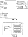
Fig. 1 is a schematic block diagram of a heating circuit in the related art; -
Fig. 2 is a schematic structural diagram of a heatable battery pack according to some examples of the present application; and -
Fig. 3 is a schematic block diagram of a heatable battery system according to some examples of the present application. - In the drawings, the drawings are not drawn to actual scale.
- Reference numerals: 1-Heatable battery pack, 2-Battery management system (BMS), 3-Drive module, 4-Second switch module; 11-Battery, 12-First switch module, 13-Heater, 14-Manual switch, 15-Current sensor.
- For the objects, technical solutions and advantages of the examples of the present application to be clearer, the technical solutions in the examples of the present application will be clearly and completely described below in conjunction with the drawings in the examples of the present application, and it is apparent that the described examples are a part of the examples of the present application rather than all the examples. Based on the examples in the present application, all other examples obtained by those of ordinary skill in the art without creative effort fall within the protection scope of the present application.
- In the description of the present application, it is to be understood that the terms "include" and "have" and any variations thereof used herein are intended to cover non-exclusive inclusion. For example, a process, method, system, product, or device comprising a series of steps or units is not necessarily limited to those steps or units expressly listed, but may include other steps or units not expressly listed or inherent to the process, method, product, or device.
- Moreover, in the present application, unless otherwise expressly specified and limited, the technical terms "connect," "connected," "fix," "mount," and the like should be understood in a broad sense, such as a mechanical connection, or an electrical connection; a direct connection, an indirect connection through an intermediate medium, an internal connection of two elements, or interaction between two elements. Unless otherwise clearly defined, for those of ordinary skill in the art, the specific meanings of the above terms in the present application can be understood according to specific situations.
- It is to be understood that, the orientation or positional relationships indicated by the technical terms "length," "width," "upper," "lower," "front," "rear," "left," "right," "vertical," "horizontal," "top," "bottom," "inner," "outer," and the like are based on the orientation or positional relationships shown in the drawings and are only for facilitating the description of the present application and simplifying the description, rather than indicating or implying that the apparatus or element referred to must have a particular orientation or be constructed and operated in a particular orientation, and therefore will not be interpreted as limiting the present application.
- In addition, the terms "first" and "second" are used for descriptive purposes only, and cannot be construed as indicating or implying relative importance or implicitly indicating the number of technical features indicated. Therefore, a feature defined by "first" or "second" may expressly or implicitly include one or more of the features.
- An electric vehicle refers to a vehicle powered by a power battery. Due to material limitation, a power battery can stably exert its best performance only in a rated ambient temperature range. Therefore, when using an electric vehicle in a region with a low ambient temperature or in winter, the power battery needs to be heated to the rated ambient temperature range. For example, when the ambient temperature of the power battery reaches 20°C to 60°C, it is most beneficial to charge the battery. It should be noted that both the charging process and the discharging process of the battery have a rated ambient temperature range. The rated ambient temperature range corresponding to the charging process and the rated ambient temperature range corresponding to the discharging process may be the same or different, specifically depending on the properties of the power battery itself.
- At present, please refer to
Fig. 1 , a heater is arranged in a battery pack of each power battery, and the heaters and a drive module in the high-voltage box are connected in series to form a series loop, so that the drive module can perform high-voltage power supply to the various heaters through the series loop, and then the batteries are heated by the heaters. The drive module is connected to a Battery Management System (BMS), so that the BMS controls whether the drive module outputs a voltage. In addition, the drive module may further be connected in a charging loop formed by connecting batteries in the battery packs in series (the connection relationship is not shown in the figure), so that the batteries are charged by the drive module. - Specifically, at least one high-voltage relay is connected in series in the series loop formed by connecting various heaters and the drive module in series. In
Fig. 1 , two high-voltage relays connected in series are used as an example, and a control end of each high-voltage relay is connected to the BMS (the connection relationship is not shown in the drawing). The BMS is further connected to a detection end of each battery pack (the connection relationship is not shown in the drawing), and configured to detect a current temperature of each battery pack. When detecting that the current temperature of each battery pack meets a preset heating condition, specifically when the current temperature is within a preset heating temperature range of the battery pack, the BMS may control each high-voltage relay to be turned on, so as to turn on the above series loop. At this time, the heaters start heating until the current temperatures of the battery packs no longer meet the preset heating condition, and the BMS may control the high-voltage relays to be turned off, so as to turn off the above series loop, and the heaters will no longer perform heating. - The number of heaters in the series loop is usually large, and each heater also has a rated working voltage; therefore, in order to meet the rated working voltage of each heater, the drive module usually needs to perform high-voltage power supply on the series loop. For example, if the number of heaters in the series loop is 30, and the rated working voltage of each heater is 20V, the voltage required to be supplied by the drive module is at least 30*20V=600V. However, the safety of high-voltage power supply is low, and it is prone to high-voltage breakdown of insulation, ignition, and other undesirable phenomena, which may even affect the safety of electric vehicles in severe cases.
- Based on the above problems, the present application proposes the following technical idea: a battery in each battery pack performs low-voltage power supply on a respective heater, without the need for high-voltage power supply by a drive module, which significantly improves the safety of power supply.
- An example of the present application provides
heatable battery pack 1. Referring toFig. 2 ,heatable battery pack 1 includesbattery 11,first switch module 12, andheater 13.Battery 11,first switch module 12, andheater 13 are connected in series to form a heating loop, whereinfirst switch module 12 turns on the heating loop after a drive signal is received. - In some embodiments,
battery 11 inbattery pack 1 performs low-voltage power supply forheater 13, and therefore, the heating loop formed by series connection may be formed by connection with a low-voltage wiring harness. Compared with using a high-voltage wiring harness, using the low-voltage wiring harness no longer requires reserving a high-voltage wiring harness connection interface for leading out a high-voltage wiring harness out on the battery pack, which saves the cost of reserving the high-voltage wiring harness connection interface and another component (such as a connector, a seal ring, and a box reserved features) on the battery pack. It is only necessary to integrate the low-voltage wiring harness into an original low-voltage wiring harness of the battery pack, which significantly reduces the circuit cost. The low-voltage wiring harness may carry, for example, a voltage of 12V to 24V, and the high-voltage wiring harness may, for example, carry a voltage of 600V to 700V - In some embodiments, a control end of
first switch module 12 may be connected to a drive module in a high-voltage box through a second switch module. When a BMS determines thatheater 13 needs to heatbattery 11, the second switch module will be turned on so as to connect the drive module and the control end offirst switch module 12. At this time,first switch module 12 may receive a drive signal sent by the drive module, andfirst switch module 12 may turn on the heating loop so thatheater 13heats battery 11. - Compared with the related art in which heaters in various battery packs are connected in series to both ends of a drive module in a high-voltage box, so as to perform high-voltage power supply on the heaters by the high-voltage box through a series loop, the example of the application directly performs low-voltage power supply on respective heaters by batteries in the battery packs, and the high-voltage power supply by the drive module is not required, which significantly improves the safety of power supply. In addition, in this example, it is no longer necessary to set a high-voltage wiring harness to connect the heaters, and only a low-voltage wiring harness is used for connecting the battery, a first switch module, and the heater. The cost of the low-voltage wiring harness is much lower than that of the high-voltage wiring harness, and this example effectively reduces the cost of the entire heating circuit.
- In some examples, referring to
Fig. 2 ,heatable battery pack 1 further includesmanual switch 14.Manual switch 14 is connected in series in the heating loop. InFig. 2 ,manual switch 14 connected in series betweenbattery 11 andfirst switch module 12 is shown as an example. - Specifically, the technician may turn on or off
manual switch 14 manually to turn on or off the heating loop, and then control whetherheater 13 works. - In this example, the manual switch is further connected in series in the heating loop. If the first switch module cannot be turned off due to adhesion, a technician may turn off the heating loop through the manual switch to prevent the battery from being overheated and improve the safety of the heatable battery pack.
- In some examples, referring to
Fig. 2 ,heatable battery pack 1 further includescurrent sensor 15, andcurrent sensor 15 is connected in series in the heating loop. InFig. 2 ,current sensor 15 connected in series betweenbattery 11 andheater 13 is shown as example. - Specifically,
current sensor 15 is configured to measure a current of the heating loop. - In some examples,
current sensor 15 may be connected to the BMS (not shown in the connection relationship diagram), and the BMS may calculate a current battery capacity ofbattery 11 according to the magnitude of the current measured bycurrent sensor 15, and turn on the second switch module when it is determined thatheater 13 needs to heatbattery 11 in a discharging state, and the current battery capacity ofbattery 11 is greater than a preset threshold, so as to indirectly turn on the heating loop. - In the above example, the problem of over-discharging of the battery caused by heating the heater when the current battery capacity is low may be avoided.
- In some examples, the technician may determine a current state of the heating loop according to the magnitude of the current of the heating loop measured by
current sensor 15. If the current on the heating loop is too large, the heating loop may be turned off throughmanual switch 14 to avoid the large current from damaging the battery pack.Current sensor 15 may also be connected to the BMS. When determining that the current on the heating loop is too large, the BMS may indirectly turn offfirst switch module 12 by turning off the second switch module, thereby turning off the heating loop, so as to avoid the large current from damaging the battery pack. - In some examples,
first switch module 12 may be a low-voltage relay. - Specifically,
first switch module 12 may be a high-voltage relay, a low-voltage relay, or a switch of another structure, as long as the control end offirst switch module 12 can turn on the heating loop when receiving the drive signal, wherein the drive signal may both be at a high level or a low level, or a voltage in any voltage range, which is not limited here. - In this example, the heater in the example of the present application does not require high-voltage power supply by the drive module in the high-voltage box, but accepts low-voltage power supply by the battery, and therefore, the first switch module may use a low-voltage relay, which can reduce the cost of the heatable battery pack to a certain extent compared with the use of a switch module such as the high-voltage relay.
- In some examples, referring to
Fig. 2 , the heating circuit inheatable battery pack 1 is formed bybattery 11,first switch module 12,heater 13,manual switch 14, andcurrent sensor 15 connected in series. - An example of the present application provides a heatable battery system. Referring to
Fig. 3 , the heatable battery system includes battery management system 2, drive module 3, second switch module 4, and N heatable battery packs 1 according to any of the above examples, wherein N is an integer greater than 1. InFig. 3 ,heatable battery pack 1 includingbattery 11,first switch module 12,heater 13,manual switch 14, andcurrent sensor 15 is shown as an example. - Battery management system 2 is respectively connected to a detection end of each
battery pack 1 and a control end of second switch module 4, and a control end offirst switch module 12 in each battery pack is connected to drive module 3 through second switch module 4. - In the related art, the power supply voltage provided by the drive module in the high-voltage box and the number of heaters connected in series match with each other, and the number of the battery packs and the power supply voltage provided by the high-voltage box need to be adjusted synchronously. Without changing the power supply voltage provided by the high-voltage box, if several heaters are missed by mistake by the technician during the series connection, it will lead to an increase in the voltage carried by each heater. For example, if the number of heaters in the series loop is 30, and a rated working voltage of each heater is 20V, the drive module needs to provide at least a voltage of 30*20V=600V. If only 20 heaters are connected in series due to mistakes, a voltage that each heater needs to carry is 600V/20 = 30V, which may lead to insulation failure of the heaters due to overvoltage, further lead to the insulation failure of battery packs and connecting wires, and may even cause accidents such as battery pack explosion. Compared with the aforementioned, in this example, the heating loops of various battery packs are independent of each other, and the power supply voltage of the heater is only related to the voltage of the corresponding battery, and is not limited by the power supply voltage of by the high-voltage box and the number of the heaters. When the number of battery packs needs to be increased or decreased, it is only necessary to turn on or turn off the battery pack and the second switch module, which is beneficial to platformization.
- In addition, the heaters in the battery packs do not need to be connected with a high-voltage wiring harness, and therefore, there is no need to provide a high-voltage interface for leading out the high-voltage wiring harness on each battery pack, but an original low-voltage interface of each battery pack is directly used for leading out a low-voltage wiring harness connected to the control end of the first switch module, and the other end of the low-voltage wiring harness is connected to the drive module through the second switch module, so that the drive module outputs a drive signal to the control end of the first switch module through the low-voltage wiring harness. There is no need to arrange a high-voltage wiring harness connection interface on the battery pack, nor to use a high-voltage wiring harness for connection. Compared with the increased cost of arranging a low-voltage relay in the battery pack and connecting the low-voltage wiring harness to form a heating loop, the former saves more costs. Therefore, the cost of the entire heating circuit can be effectively reduced.
- In some examples, battery management system 2, drive module 3, and second switch module 4 are all integrated on a circuit board of the high-voltage box.
- In some examples, second switch module 4 is a low-voltage relay. The heater in the example of the present application does not require high-voltage power supply by the drive module in the high-voltage box, but accepts low-voltage power supply by the battery, and therefore, the second switch module may use a low-voltage relay, which can reduce the cost of the heatable battery system to a certain extent compared with the use of a switch module such as the high-voltage relay.
- An example of the present application provides a vehicle, including the above heatable battery system.
- The above examples are merely used for illustrating rather than limiting the technical solutions of the present application. Although the present application has been described in detail with reference to the above various examples, those of ordinary skill in the art should understand that the technical solutions recorded in the above various examples can still be modified, or some or all of the technical features therein can be equivalently substituted. However, such modifications or substitutions do not make the essence of the corresponding technical solutions depart from the scope of the technical solutions of the various examples of the present application.
Claims (16)
- A heatable battery pack, comprising: a battery, a first switch module, and a heater;
the battery, the first switch module, and the heater are connected in series to form a heating loop, wherein the first switch module turns on the heating loop after a drive signal is received. - The heatable battery pack according to claim 1, wherein the heatable battery pack further comprises a manual switch, and the manual switch is connected in series in the heating loop.
- The heatable battery pack according to claim 1 or 2, wherein the heatable battery pack further comprises a current sensor, and the current sensor is connected in series in the heating loop.
- The heatable battery pack according to any one of claims 1 to 3, wherein the first switch module is a low-voltage relay.
- The heatable battery pack according to any one of claims 1 to 4, wherein the battery, the first switch module, and the heater are connected in series through a low-voltage wiring harness to form a heating loop.
- The heatable battery pack according to claim 5, wherein the low-voltage wiring harness is integrated into an original low-voltage wiring harness of the heatable battery pack.
- A heatable battery system, comprising: a battery management system, a drive module, a second switch module, and N heatable battery packs according to any one of claims 1 to 6, wherein N is an integer greater than 1, the drive module is configured to output a drive signal;
the battery management system is respectively connected to a detection end of each of the battery packs and a control end of the second switch module, and a control end of the first switch module in each of the battery packs is connected to the drive module through the second switch module. - The heatable battery system according to claim 7, wherein the battery management system, the drive module, and the second switch module are all integrated on a circuit board in the high-voltage box.
- The heatable battery system according to claim 7 or 8, wherein the second switch module (4) is a low-voltage relay.
- The heatable battery system according to any one of claims 7 to 9, wherein the battery management system is configured to turn on the second switch module when it is determined that the heater in the heatable battery pack is required to heat the battery.
- The heatable battery system according to any one of claims 7 to 10, wherein the battery management system is connected to a current sensor in the heatable battery pack.
- The heatable battery system according to claim 11, wherein the battery management system is configured to calculate a current battery capacity of the battery in the heatable battery pack according to a magnitude of a current measured by the current sensor, and turn on the second switch module when determining that the heater in the heatable battery pack is required to heat the battery, and the current battery capacity of the battery is greater than a preset threshold.
- The heatable battery system according to claim 11, wherein the battery management system is further configured to indirectly turn off the first switch module by turning off the second switch module when it is determined that the current on the heating loop is greater than a preset current.
- The heatable battery system according to any one of claims 7 to 13, wherein a power supply voltage provided by the drive module matches the number of heaters in the heatable battery packs connected in series.
- The heatable battery system according to any one of claims 7 to 14, wherein the heater in the heatable battery pack is lead out through an original low-voltage interface of the heatable battery pack and connected to a low-voltage wiring harness of the control end of the first switch module, and the other end of the low-voltage wiring harness is connected to the drive module through the second switch module.
- A vehicle, comprising the heatable battery system according to any one of claims 7 to 15.
Applications Claiming Priority (2)
| Application Number | Priority Date | Filing Date | Title |
|---|---|---|---|
| CN202122367357.1U CN216054914U (en) | 2021-09-28 | 2021-09-28 | Heatable battery package, heatable battery system and vehicle |
| PCT/CN2022/098233 WO2023050880A1 (en) | 2021-09-28 | 2022-06-10 | Heatable battery pack, heatable battery system, and vehicle |
Publications (2)
| Publication Number | Publication Date |
|---|---|
| EP4184665A1 true EP4184665A1 (en) | 2023-05-24 |
| EP4184665A4 EP4184665A4 (en) | 2024-01-10 |
Family
ID=80546697
Family Applications (1)
| Application Number | Title | Priority Date | Filing Date |
|---|---|---|---|
| EP22789146.2A Pending EP4184665A4 (en) | 2021-09-28 | 2022-06-10 | HEATED BATTERY PACK, HEATED BATTERY SYSTEM AND VEHICLE |
Country Status (6)
| Country | Link |
|---|---|
| US (1) | US12476295B2 (en) |
| EP (1) | EP4184665A4 (en) |
| JP (1) | JP7453412B2 (en) |
| KR (1) | KR102747686B1 (en) |
| CN (1) | CN216054914U (en) |
| WO (1) | WO2023050880A1 (en) |
Families Citing this family (1)
| Publication number | Priority date | Publication date | Assignee | Title |
|---|---|---|---|---|
| CN216054914U (en) | 2021-09-28 | 2022-03-15 | 宁德时代新能源科技股份有限公司 | Heatable battery package, heatable battery system and vehicle |
Family Cites Families (15)
| Publication number | Priority date | Publication date | Assignee | Title |
|---|---|---|---|---|
| US7382102B2 (en) * | 2005-06-13 | 2008-06-03 | Chrysler Llc | Heating of batteries using reactive power |
| EP2463985B1 (en) * | 2009-08-05 | 2016-04-27 | GS Yuasa International Ltd. | Battery system |
| JPWO2011145250A1 (en) * | 2010-05-17 | 2013-07-22 | パナソニック株式会社 | Lithium ion secondary battery system and battery pack |
| US9431688B2 (en) * | 2010-05-21 | 2016-08-30 | GM Global Technology Operations LLC | Method for heating a high voltage vehicle battery |
| US9496730B2 (en) * | 2010-09-02 | 2016-11-15 | Proterra Inc. | Systems and methods for battery management |
| JP5228076B2 (en) * | 2010-09-03 | 2013-07-03 | 日立ビークルエナジー株式会社 | In-vehicle power storage device |
| WO2012105636A1 (en) * | 2011-02-02 | 2012-08-09 | 株式会社Gsユアサ | Battery system |
| JP2014038734A (en) * | 2012-08-13 | 2014-02-27 | Sumitomo Electric Ind Ltd | Molten salt cell system and battery system |
| CN102842935A (en) * | 2012-09-20 | 2012-12-26 | 上海广为美线电源电器有限公司 | Lithium battery emergency starting power supply with low temperature automatic pre-heating function |
| CN105529508A (en) * | 2014-06-30 | 2016-04-27 | 比亚迪股份有限公司 | Battery heating systems, battery installations and electric vehicles |
| CN104442636A (en) * | 2014-10-14 | 2015-03-25 | 中国人民解放军63983部队 | Self-heating device of vehicle-mounted storage batteries |
| US10744885B2 (en) * | 2016-11-21 | 2020-08-18 | Ford Global Technologies, Llc | Battery pre-heating prior to fast charge |
| CN111216600B (en) * | 2018-11-27 | 2024-04-16 | 中信国安盟固利动力科技有限公司 | A battery system with adjustable heating speed and control method thereof |
| CN209479443U (en) * | 2018-12-29 | 2019-10-11 | 宁德时代新能源科技股份有限公司 | A kind of battery heating system |
| CN216054914U (en) * | 2021-09-28 | 2022-03-15 | 宁德时代新能源科技股份有限公司 | Heatable battery package, heatable battery system and vehicle |
-
2021
- 2021-09-28 CN CN202122367357.1U patent/CN216054914U/en active Active
-
2022
- 2022-06-10 WO PCT/CN2022/098233 patent/WO2023050880A1/en not_active Ceased
- 2022-06-10 KR KR1020227035496A patent/KR102747686B1/en active Active
- 2022-06-10 EP EP22789146.2A patent/EP4184665A4/en active Pending
- 2022-06-10 JP JP2022562817A patent/JP7453412B2/en active Active
- 2022-12-22 US US18/087,248 patent/US12476295B2/en active Active
Also Published As
| Publication number | Publication date |
|---|---|
| KR20230048244A (en) | 2023-04-11 |
| US12476295B2 (en) | 2025-11-18 |
| JP2023547003A (en) | 2023-11-09 |
| EP4184665A4 (en) | 2024-01-10 |
| JP7453412B2 (en) | 2024-03-19 |
| US20230125606A1 (en) | 2023-04-27 |
| CN216054914U (en) | 2022-03-15 |
| WO2023050880A1 (en) | 2023-04-06 |
| KR102747686B1 (en) | 2024-12-27 |
Similar Documents
| Publication | Publication Date | Title |
|---|---|---|
| EP2853000B1 (en) | Power system of electric vehicle, electric vehicle comprising the same and method for heating battery group of electric vehicle | |
| EP2853003B1 (en) | Power system of electric vehicle, electric vehicle comprising the same and method for heating battery group of electric vehicle | |
| US11502509B2 (en) | Jumper cable and method to jump start an automobile | |
| KR101571943B1 (en) | Battery charging control device | |
| CN103879291B (en) | A kind of safety device of vehicle | |
| CN105529508A (en) | Battery heating systems, battery installations and electric vehicles | |
| KR20190004138A (en) | System for controlling temperature of battery and method thereof | |
| JP2018026300A (en) | Charging system | |
| CN110329110B (en) | Battery safety control system and control method for electric motor coach | |
| EP2853002A1 (en) | Power system of electric vehicle, electric vehicle comprising the same and method for heating battery group of electric vehicle | |
| EP2837056A1 (en) | Power system of electric vehicle, electric vehicle comprising the same and method for heating battery group of electric vehicle | |
| EP3232049A1 (en) | Automobile starting control system and automobile | |
| CN105459834A (en) | Multiple-protection high-voltage distribution box applied to new energy automobile | |
| EP4184665A1 (en) | Heatable battery pack, heatable battery system, and vehicle | |
| CN115639447A (en) | Insulation detection circuit and insulation detection method for vehicle high-voltage line | |
| CN113492702A (en) | Bidirectional vehicle-mounted charger, vehicle-mounted power supply system, charging control method and automobile | |
| WO2013174277A1 (en) | Power system of electric vehicle, electric vehicle comprising the same and method for heating battery group of electric vehicle | |
| CN111934038B (en) | Battery heating device and heating method | |
| CN116203345B (en) | Vehicle and electric leakage detection positioning method thereof | |
| CN116203456B (en) | Vehicle and leakage detection and positioning method thereof | |
| CN208035982U (en) | It is a kind of to realize that power battery exchanges the device of fast charge by electric machine controller | |
| WO2013174280A1 (en) | Power system of electric vehicle, electric vehicle comprising the same and method for heating battery group of electric vehicle | |
| KR100219324B1 (en) | Battery preheat apparatus of electric car | |
| EP2597721A1 (en) | Method and device for heating a battery | |
| KR102717586B1 (en) | All-in-one power relay assembly for charging and discharging for forklifts |
Legal Events
| Date | Code | Title | Description |
|---|---|---|---|
| STAA | Information on the status of an ep patent application or granted ep patent |
Free format text: STATUS: UNKNOWN |
|
| STAA | Information on the status of an ep patent application or granted ep patent |
Free format text: STATUS: THE INTERNATIONAL PUBLICATION HAS BEEN MADE |
|
| PUAI | Public reference made under article 153(3) epc to a published international application that has entered the european phase |
Free format text: ORIGINAL CODE: 0009012 |
|
| STAA | Information on the status of an ep patent application or granted ep patent |
Free format text: STATUS: REQUEST FOR EXAMINATION WAS MADE |
|
| 17P | Request for examination filed |
Effective date: 20221031 |
|
| AK | Designated contracting states |
Kind code of ref document: A1 Designated state(s): AL AT BE BG CH CY CZ DE DK EE ES FI FR GB GR HR HU IE IS IT LI LT LU LV MC MK MT NL NO PL PT RO RS SE SI SK SM TR |
|
| A4 | Supplementary search report drawn up and despatched |
Effective date: 20231212 |
|
| RIC1 | Information provided on ipc code assigned before grant |
Ipc: H01M 10/637 20140101ALI20231206BHEP Ipc: B60L 1/02 20060101ALI20231206BHEP Ipc: H01M 10/6571 20140101ALI20231206BHEP Ipc: H01M 50/249 20210101ALI20231206BHEP Ipc: H01M 10/48 20060101ALI20231206BHEP Ipc: H01M 10/657 20140101ALI20231206BHEP Ipc: H01M 10/625 20140101ALI20231206BHEP Ipc: H01M 50/298 20210101ALI20231206BHEP Ipc: H01M 10/42 20060101ALI20231206BHEP Ipc: B60L 58/27 20190101ALI20231206BHEP Ipc: H01M 10/63 20140101ALI20231206BHEP Ipc: H01M 10/615 20140101AFI20231206BHEP |
|
| RAP1 | Party data changed (applicant data changed or rights of an application transferred) |
Owner name: CONTEMPORARY AMPEREX TECHNOLOGY(HONG KONG) LIMITED |
|
| DAV | Request for validation of the european patent (deleted) | ||
| DAX | Request for extension of the european patent (deleted) |