EP4184632A1 - Button-type secondary battery and assembly device thereof - Google Patents
Button-type secondary battery and assembly device thereof Download PDFInfo
- Publication number
- EP4184632A1 EP4184632A1 EP21872945.7A EP21872945A EP4184632A1 EP 4184632 A1 EP4184632 A1 EP 4184632A1 EP 21872945 A EP21872945 A EP 21872945A EP 4184632 A1 EP4184632 A1 EP 4184632A1
- Authority
- EP
- European Patent Office
- Prior art keywords
- cap
- electrode tab
- button
- secondary battery
- type secondary
- Prior art date
- Legal status (The legal status is an assumption and is not a legal conclusion. Google has not performed a legal analysis and makes no representation as to the accuracy of the status listed.)
- Pending
Links
Images


Classifications
-
- H—ELECTRICITY
- H01—ELECTRIC ELEMENTS
- H01M—PROCESSES OR MEANS, e.g. BATTERIES, FOR THE DIRECT CONVERSION OF CHEMICAL ENERGY INTO ELECTRICAL ENERGY
- H01M50/00—Constructional details or processes of manufacture of the non-active parts of electrochemical cells other than fuel cells, e.g. hybrid cells
- H01M50/50—Current conducting connections for cells or batteries
- H01M50/528—Fixed electrical connections, i.e. not intended for disconnection
-
- H—ELECTRICITY
- H01—ELECTRIC ELEMENTS
- H01M—PROCESSES OR MEANS, e.g. BATTERIES, FOR THE DIRECT CONVERSION OF CHEMICAL ENERGY INTO ELECTRICAL ENERGY
- H01M10/00—Secondary cells; Manufacture thereof
- H01M10/04—Construction or manufacture in general
- H01M10/0422—Cells or battery with cylindrical casing
- H01M10/0427—Button cells
-
- H—ELECTRICITY
- H01—ELECTRIC ELEMENTS
- H01M—PROCESSES OR MEANS, e.g. BATTERIES, FOR THE DIRECT CONVERSION OF CHEMICAL ENERGY INTO ELECTRICAL ENERGY
- H01M10/00—Secondary cells; Manufacture thereof
- H01M10/04—Construction or manufacture in general
-
- H—ELECTRICITY
- H01—ELECTRIC ELEMENTS
- H01M—PROCESSES OR MEANS, e.g. BATTERIES, FOR THE DIRECT CONVERSION OF CHEMICAL ENERGY INTO ELECTRICAL ENERGY
- H01M50/00—Constructional details or processes of manufacture of the non-active parts of electrochemical cells other than fuel cells, e.g. hybrid cells
- H01M50/10—Primary casings; Jackets or wrappings
- H01M50/102—Primary casings; Jackets or wrappings characterised by their shape or physical structure
- H01M50/103—Primary casings; Jackets or wrappings characterised by their shape or physical structure prismatic or rectangular
-
- H—ELECTRICITY
- H01—ELECTRIC ELEMENTS
- H01M—PROCESSES OR MEANS, e.g. BATTERIES, FOR THE DIRECT CONVERSION OF CHEMICAL ENERGY INTO ELECTRICAL ENERGY
- H01M50/00—Constructional details or processes of manufacture of the non-active parts of electrochemical cells other than fuel cells, e.g. hybrid cells
- H01M50/10—Primary casings; Jackets or wrappings
- H01M50/102—Primary casings; Jackets or wrappings characterised by their shape or physical structure
- H01M50/109—Primary casings; Jackets or wrappings characterised by their shape or physical structure of button or coin shape
-
- H—ELECTRICITY
- H01—ELECTRIC ELEMENTS
- H01M—PROCESSES OR MEANS, e.g. BATTERIES, FOR THE DIRECT CONVERSION OF CHEMICAL ENERGY INTO ELECTRICAL ENERGY
- H01M50/00—Constructional details or processes of manufacture of the non-active parts of electrochemical cells other than fuel cells, e.g. hybrid cells
- H01M50/10—Primary casings; Jackets or wrappings
- H01M50/147—Lids or covers
- H01M50/148—Lids or covers characterised by their shape
- H01M50/153—Lids or covers characterised by their shape for button or coin cells
-
- H—ELECTRICITY
- H01—ELECTRIC ELEMENTS
- H01M—PROCESSES OR MEANS, e.g. BATTERIES, FOR THE DIRECT CONVERSION OF CHEMICAL ENERGY INTO ELECTRICAL ENERGY
- H01M50/00—Constructional details or processes of manufacture of the non-active parts of electrochemical cells other than fuel cells, e.g. hybrid cells
- H01M50/50—Current conducting connections for cells or batteries
- H01M50/531—Electrode connections inside a battery casing
- H01M50/533—Electrode connections inside a battery casing characterised by the shape of the leads or tabs
-
- H—ELECTRICITY
- H01—ELECTRIC ELEMENTS
- H01M—PROCESSES OR MEANS, e.g. BATTERIES, FOR THE DIRECT CONVERSION OF CHEMICAL ENERGY INTO ELECTRICAL ENERGY
- H01M10/00—Secondary cells; Manufacture thereof
- H01M10/04—Construction or manufacture in general
- H01M10/0404—Machines for assembling batteries
-
- Y—GENERAL TAGGING OF NEW TECHNOLOGICAL DEVELOPMENTS; GENERAL TAGGING OF CROSS-SECTIONAL TECHNOLOGIES SPANNING OVER SEVERAL SECTIONS OF THE IPC; TECHNICAL SUBJECTS COVERED BY FORMER USPC CROSS-REFERENCE ART COLLECTIONS [XRACs] AND DIGESTS
- Y02—TECHNOLOGIES OR APPLICATIONS FOR MITIGATION OR ADAPTATION AGAINST CLIMATE CHANGE
- Y02E—REDUCTION OF GREENHOUSE GAS [GHG] EMISSIONS, RELATED TO ENERGY GENERATION, TRANSMISSION OR DISTRIBUTION
- Y02E60/00—Enabling technologies; Technologies with a potential or indirect contribution to GHG emissions mitigation
- Y02E60/10—Energy storage using batteries
-
- Y—GENERAL TAGGING OF NEW TECHNOLOGICAL DEVELOPMENTS; GENERAL TAGGING OF CROSS-SECTIONAL TECHNOLOGIES SPANNING OVER SEVERAL SECTIONS OF THE IPC; TECHNICAL SUBJECTS COVERED BY FORMER USPC CROSS-REFERENCE ART COLLECTIONS [XRACs] AND DIGESTS
- Y02—TECHNOLOGIES OR APPLICATIONS FOR MITIGATION OR ADAPTATION AGAINST CLIMATE CHANGE
- Y02P—CLIMATE CHANGE MITIGATION TECHNOLOGIES IN THE PRODUCTION OR PROCESSING OF GOODS
- Y02P70/00—Climate change mitigation technologies in the production process for final industrial or consumer products
- Y02P70/50—Manufacturing or production processes characterised by the final manufactured product
Definitions
- the cap holder When the cap holder couples the cap to the can, the cap holder may allow the cap to rotate so that a lower edge of the cap is in contact with an upper edge of the can and allow the cap to descend so that a side surface of the can is inserted into a side surface of the cap.
- the guide may be controlled to vary in pressing force according to a thickness of the electrode tab.
- the cap holder grips the cap through the negative pressure, it does not cause the deformation or traces on the cap due to the grip.
- FIG. 1 is a view sequentially illustrating states in which a cap behaves while assembling is performed through a device for assembling a button-type secondary battery according to the present invention
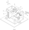
- FIG. 2 is a perspective view of the device for assembling the button-type secondary battery according to an embodiment of the present invention
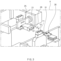
- FIG. 3 is a partial enlarged view illustrating a portion A of FIG. 2 .
- the device for assembling the button-type secondary battery provided in this embodiment comprises a can holder 10, a cap holder 20, and a guide 30.
- an electrode assembly 1 is mounted in the can 3 in a state in which a negative electrode tab extending from a bottom surface of the electrode assembly 1 is welded to the can 3, and a positive electrode tab 2 extending from a top surface of the electrode assembly 1 is welded at a predetermined point W on an inner surface of the can 4.
- the cap 4 and the can 3 are provided in a state ⁇ a> in FIG. 1 when seated on a cap holder 20 and a can holder 10, which will be described later.
- the electrode assembly may be seated in reverse.
- a groove 22 having an inner diameter so that the cap is inserted to be fixed is punched in the upper coupling plate 21.
- the upper coupling plate 21 may be connected to an external vacuum device (not shown) through a hose 26 to fix the cap 4.
- a rotation direction means a rotation direction on an XY plane in FIG. 2 as a rotation direction in which the cap 4 is covered on the can 3.
- the second sliding part 24 may be connected to the first sliding part 23 to be slid in an X direction in FIG. 2 , which is the same direction as the sliding direction of a guide 30 to be slid.
- the first sliding part 23 may also be driven by the motor or pneumatic or hydraulic pressure.
Landscapes
- Chemical & Material Sciences (AREA)
- Chemical Kinetics & Catalysis (AREA)
- Electrochemistry (AREA)
- General Chemical & Material Sciences (AREA)
- Engineering & Computer Science (AREA)
- Manufacturing & Machinery (AREA)
- Sealing Battery Cases Or Jackets (AREA)
- Secondary Cells (AREA)
- Connection Of Batteries Or Terminals (AREA)
Abstract
Description
- The present application claims the benefit of the priority of
Korean Patent Application Nos. 10-2020-0124295, filed on September 24, 2020 10-2021-0125278, filed on September 17, 2021 - The present invention relates to a button-type secondary battery and a device for assembling the same, and more particularly, to a device for assembling a button-type secondary battery in which, when a bending point that induces bending of an electrode tab (a positive electrode tab or a negative electrode tab) is formed at a predetermined position so that a cap and a can are coupled to each other, the electrode tab is bent as intended, and a button-type secondary battery manufactured through the assembling device.
- A button-type battery commonly used as a coin-type battery or a button-type battery has a thin button shape of which a diameter is greater than a height and is widely used in various devices such as remote controllers, clocks, toys, computer parts, and the like.
- Such a button-type battery is mainly manufactured as a non-rechargeable primary battery, but is also widely manufactured as a secondary battery that is chargeable and dischargeable as miniaturized devices are developed. Also, the button-type secondary battery is manufactured to have a structure in which an electrode assembly and an electrolyte are embedded in a case to repeatedly perform charging and discharging, like the button-type secondary battery or the cylindrical or pouch-type secondary battery.
- The button-type secondary battery has a structure in which a can having a lower side closed by a bottom surface and an opened upper side and a cap is coupled to a cap so that the opened upper side of the can is closed. The can has a schale shape, in which a sidewall protrudes to a predetermined height along a circumference of the bottom surface. For example, the can may have a schale shape having a diameter slightly greater than that of the can so that the cap is fitted into the can (in a manner in which the can and the cap are press-fitted) or a circular plate-shaped shape which covers a top surface of the can so that an edge portion thereof is fixed to an upper end of the can through welding (in a manner in which the can and the cap are coupled to each other through the welding). Here, even if the cap has the circular plate shape as well as the cap has the schale shape similar to the can, it is necessary to couple the cap to the can in the correct position so that the edge of the cap is fitted into the upper end of the can.
- An electrode assembly, in which a positive electrode, a separator, a negative electrode are wound in a state of being stacked, and an electrode are mounted in the can. The electrode assembly has a structure that is wound in a state in which the separator, the negative electrode, the separator, and the positive electrode are stacked around a core, and when the core is removed, a central hole is formed in a center, and a center pin is selectively inserted into the central hole.
- Thus, the electrode assembly has a structure, in which each of both surface thereof is formed in a circular shape, a negative electrode tab extending from the negative electrode protrudes from one surface, and a positive electrode tab extending from the positive electrode protrudes from the other surface. Here, when the electrode assembly is mounted in the can, in one surface and the other surface, one is a surface facing a lower side, and the other is a surface facing an upper side.
- Thus, one of the two electrode tabs (the positive electrode tab and the negative electrode tab) is welded to an inner bottom surface of the can before the electrode assembly is mounted in the can, and the other of the two electrode tabs is welded to a ceiling surface (a surface facing the electrode assembly when the cap is coupled to the can) inside the cap after the electrode assembly is mounted in the can.
- In addition, in a state in which a gasket having no electrical conductivity is disposed at a point at which the cap and the can are in contact with each other to prevent short circuit from occurring when the cap and the can are coupled to each other, a portion of the edge of the cap is coupled to the can in a state of being bent to press the gasket.
- However, when the cap and the can are coupled to each other, a point at which the electrode tab (the positive electrode tab or the negative electrode tab) is bent is not constant. Thus, when the cap and the can are coupled to each other, there is a possibility that the electrode tab presses or hits the electrode assembly.
- Also, if the electrode tab is bent at an incorrect point or in an unintended direction, an interference may occur when the cap is coupled.
- Therefore, a main object of the prevent invention is to provide a device for assembling a button-type secondary battery in which, a point (bending point), at which an electrode tab is bent, is formed at a constant position so that the electrode tab is bent in an intended shape when a cap and a can are coupled to each other, thereby solving the above problem, and a button-type secondary battery that is assembled by the assembling device.
- A button-type secondary battery, in which an electrode assembly is mounted in a can having a closed lower side and an opened upper side, and when an electrode tab extending from the electrode assembly is provided in a state of being welded to an inner surface of a cap coupled to cover the upper side of the can, the can and the cap are assembled with each other, according to the present invention for achieving the above object comprises: a can holder configured to fix the can so that a top surface of the electrode assembly faces an upper side; a cap holder configured to grip the cap so that the cap rotates and ascends/descends; and a guide that is slidable toward the electrode tab so that an end of one side of the guide presses a predetermined point to form a bending point, at which bending of the electrode tab occurs when the electrode tab is bent, wherein, when the guide forms the bending point at the electrode tab, the cap holder allows the cap to be coupled to the can so that the opened upper side of the can is closed.
- Before the guide approaches the electrode tab to form the bending point, the cap holder may allow the cap to rotate in a direction perpendicular to a sliding direction of the guide.
- When the cap rotates in the direction perpendicular to the sliding direction of the guide, the can and the cap may be fixed to be perpendicular to each other.
- A vacuum device configured to generate a negative pressure so that the gripping may be performed at a contact point with the cap by the negative pressure is coupled to the cap holder.
- When the cap holder couples the cap to the can, the cap holder may allow the cap to rotate so that a lower edge of the cap is in contact with an upper edge of the can and allow the cap to descend so that a side surface of the can is inserted into a side surface of the cap.
- The cap holder and the guide may be disposed to face each other with the can holder therebetween.
- The cap holder may comprise: an upper coupling plate into which the cap is inserted to be fixed through the vacuum device; a first sliding part slid toward the can holder in a sliding direction that is the same as a direction in which the guide is slid; a second sliding part coupled to the first sliding part and slid to allow the cap to ascend or descend; and a rotation part having one end, to which the upper coupling plate is coupled, and the other end that is coupled to be rotatable on the second sliding part, wherein the first sliding part, the second sliding part, and the rotation part may be simultaneously or individually operable.
- The can holder may comprise a lower coupling plate in which a groove is punched so that the can is inserted to be fixed.
- The can holder may fix two or more cans, the cap holder may grip caps having the same number as the cans, and the guide may form the bending points at the electrodes welded to the cap holders at the same time through one sliding.
- When the guide presses the electrode tab to form the bending point, the cap holder may fix the cap so that an opposite side of the pressed point is supported by an inner surface of the cap.
- The guide may be controlled to vary in pressing force according to a thickness of the electrode tab.
- Furthermore, a button-type secondary battery, in which, when an electrode assembly is mounted in a can having a closed lower side and an opened upper side, a cap is coupled to close the upper side of the can, according to the present invention comprises: an electrode tab having one end coupled to the electrode assembly and the other end bonded to an inner surface of the cap, wherein the electrode tab is bent between the electrode assembly and the cap, and a bending point C pressed by an external pressure to induce bending is formed at the electrode tab, wherein, the bending is performed at the bending point (C).
- the bending point (C) is a point (a point at which rigidity decreases, ductility increases, or elastic deformation occurs) that is pressed by the external pressure so that the electrode tab is relatively thinner in thickness or deformed in material.
- In the present invention having the above-described configuration, since the bending point is formed to induce the bending of the electrode tab (one of negative electrode tan or the positive electrode tab, which is connected to the cap) before the cap and the can are coupled to each other, the cap and the can may be assembled in the state in which the electrode tab is uniformly bent.
- In the electrode tab, the bending point may be formed at the point that is pressed by the guide. Here, the cup holder may be movable and rotatable to form the bending point at the accurate position so that the electrode tab, of which the end is welded to the cap, is disposed at the proper position when the guide approaches the bending point.
- Since the cap holder grips the cap through the negative pressure, it does not cause the deformation or traces on the cap due to the grip.
- In addition, since the can holder and the cap holder fix or grip the plurality of cans and caps, the plurality of cans and caps may be assembled at the same time.
- Furthermore, since the guide is controlled to vary in pressure applied according to the thickness of the electrode tab, the bending point may be formed at the electrode tabs having various thicknesses and materials.
-
-
FIG. 1 is a view sequentially illustrating states in which a cap behaves while assembling is performed through a device for assembling a button-type secondary battery according to the present invention. -
FIG. 2 is a perspective view of the device for assembling the button-type secondary battery according to an embodiment of the present invention. -
FIG. 3 is a partial enlarged view illustrating a portion A ofFIG. 2 . -
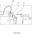
FIG. 4a is a view illustrating a state before a guide enters an electrode tab. -
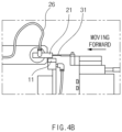
FIG. 4b is a view illustrating a state in which the guide enters the electrode tab. -
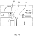
FIG. 4c is a view illustrating a state in which the guide retreats to its original position. -
FIG. 4d is a view illustrating a state in which a first sliding part approaches a can holder so that a second sliding part ascends, and a rotation part rotates. -
FIG. 4e is a view illustrating a state before the second sliding part descends. -
FIG. 4f is a view illustrating a state in which the second sliding part completely descends. - Hereinafter, preferred embodiments of the present invention will be described in detail with reference to the accompanying drawings in such a manner that the technical idea of the present invention may easily be carried out by a person with ordinary skill in the art to which the invention pertains. The present invention may, however, be embodied in different forms and should not be construed as limited to the embodiments set forth herein.
- In order to clearly describe the present invention, parts irrelevant to the description are omitted, and the same reference numerals are assigned to the same or similar components throughout the specification.
- Also, terms or words used in this specification and claims should not be restrictively interpreted as ordinary meanings or dictionary-based meanings, but should be interpreted as meanings and concepts conforming to the scope of the present invention on the basis of the principle that an inventor can properly define the concept of a term to describe and explain his or her invention in the best ways.
- The present invention relates to a device for assembling a button-type secondary battery, which couples a
cap 4 to a can 3 after forming a bending point C on anelectrode tab 2 when thecap 4 and the can 3 are coupled to each other. Hereinafter, an embodiment according to the present invention will be described in more detail with reference to the accompanying drawings. -
FIG. 1 is a view sequentially illustrating states in which a cap behaves while assembling is performed through a device for assembling a button-type secondary battery according to the present invention,FIG. 2 is a perspective view of the device for assembling the button-type secondary battery according to an embodiment of the present invention, andFIG. 3 is a partial enlarged view illustrating a portion A ofFIG. 2 . - Referring to the accompanying drawings, the device for assembling the button-type secondary battery provided in this embodiment comprises a
can holder 10, acap holder 20, and aguide 30. - Here, in the button-type secondary battery to be assembled by the assembling device provided in this embodiment, an
electrode assembly 1 is mounted in the can 3 in a state in which a negative electrode tab extending from a bottom surface of theelectrode assembly 1 is welded to the can 3, and apositive electrode tab 2 extending from a top surface of theelectrode assembly 1 is welded at a predetermined point W on an inner surface of thecan 4. Thecap 4 and the can 3 are provided in a state <a> inFIG. 1 when seated on acap holder 20 and acan holder 10, which will be described later. However, in this case, the electrode assembly may be seated in reverse. That is, theelectrode assembly 1 is mounted in the can 3 in a state in which a positive electrode tab extending from the bottom surface of theelectrode assembly 1 is welded to the can 3, and a negative electrode tab extending from the top surface of theelectrode assembly 1 is welded at a predetermined point W on an inner surface of thecap 4. - The
can holder 10 is configured to fix the can 3 so that the top surface of theelectrode assembly 1 face an upper side. That is, as more clearly illustrated inFIG. 3 , thecan holder 10 comprises alower coupling plate 11 in which agroove 12 having an inner diameter is punched so that the can 3 is inserted to be fixed, and a frame capable of fixing thelower coupling plate 11 at a predetermined height. Thus, thecan holder 10 may fix movement of the can 3 while thecap 4 is coupled to the can 3 at a predetermined height. - The
cap holder 20 is configured to grip thecap 4 so that thecap 4 rotates and ascends/descends. - That is, as illustrated in
FIGS. 2 and3 , thecap holder 20 comprises anupper coupling plate 21, a first slidingpart 23, a second slidingpart 24, and arotation part 25. - A
groove 22 having an inner diameter so that the cap is inserted to be fixed is punched in theupper coupling plate 21. In addition, theupper coupling plate 21 may be connected to an external vacuum device (not shown) through ahose 26 to fix thecap 4. - That is, a point at which air is suctioned by the vacuum device may be formed in the
groove 22 of theupper coupling plate 21, and thus, thecap 4 may be fixed by a negative pressure generated at the point. InFIG. 1 , thecap 4 has a schale shape having a closed top surface and an opened bottom surface like the can 3. However, as described above, if the can 3 and thecap 4 are not press-fitted, but coupled to each other through welding, thecap 4 may have a circular plate shape. Even if thecap 4 is formed in the circular plate shape, thecap 4 may be fixed to thecap holder 20 by the negative pressure generated in the vacuum device. - Also, the
upper coupling plate 21 is coupled to an end of one side of therotation part 25. An end of the other side of therotation part 25 may be rotatably coupled to the second slidingpart 24. Therotation part 25 may rotate by a predetermined angle at a connection point of the second slidingpart 24 by a motor or pneumatic or hydraulic pressure. Here, as illustrated inFIG. 1 , a rotation direction means a rotation direction on an XY plane inFIG. 2 as a rotation direction in which thecap 4 is covered on the can 3. - The second sliding
part 24 may allow theupper coupling part 21 and therotation part 25 to ascend and descend. That is, the second slidingpart 24 may be slid in a Y direction inFIG. 2 . The second slidingpart 24 may be also driven by the motor or pneumatic or hydraulic pressure. - The second sliding
part 24 may be connected to the first slidingpart 23 to be slid in an X direction inFIG. 2 , which is the same direction as the sliding direction of aguide 30 to be slid. The first slidingpart 23 may also be driven by the motor or pneumatic or hydraulic pressure. - In addition, the first sliding
part 23, the second slidingpart 24, and therotation part 25 may be configured to be operable simultaneously or individually. - Furthermore, the
guide 30 is disposed at an opposite side of thecap holder 20 with thecan holder 10 in a center thereof. Theguide 30 may have a structure in which a blade 32 made of a metal having hardness greater than that of theelectrode tab 2 is coupled to an end of the sliding device that is slid in the X direction. - Thus, when the
blade 31 presses a specific point of theelectrode tab 2 in a state in which theelectrode tab 2 is fixed, a bending point C may be formed at a point that is pressed by theblade 31. -
FIG. 4a is a view illustrating a state before a guide enters an electrode tab,FIG. 4b is a view illustrating a state in which the guide enters the electrode tab,FIG. 4c is a view illustrating a state in which the guide retreats to its original position,FIG. 4d is a view illustrating a state in which a first sliding part approaches a can holder so that a second sliding part ascends, and a rotation part rotates,FIG. 4e is a view illustrating a state before the second sliding part descends, andFIG. 4f is a view illustrating a state in which the second sliding part completely descends. However, in order to avoid complication of the drawings, inFIGS. 4a to 4f , a state in which thecap 4 and the can 3 are deleted is illustrated. - Referring to
FIGS. 1 and4A to4F , a secondary battery is provided in a state in which the can 3 is seated on thelower coupling plate 11 of thecan holder 10, and thecap 4 is gripped to theupper coupling plate 21 of thecap holder 20. Here, theelectrode assembly 1 may be in a state of being stated in the can 3, and theelectrode tab 2 extending from theelectrode assembly 1 may be one of the positive electrode tab or the negative electrode tab and in a state of being welded to a specific point W on an inner ceiling surface of thecap 4. In addition, the other of the positive electrode tab or the negative electrode tab is in a state of being welded to an inner bottom surface of the can 3. - That is, as illustrated in
FIG. 4a , thecan holder 10 and thecap holder 20 are disposed as in a state <a> ofFIG. 1 . - Also, in the state of
FIG. 4a , the sliding device of theguide 30 approaches theelectrode tab 2 as illustrated inFIG. 4b . An end of theblade 31 coupled to the sliding device presses theelectrode tab 2 so that theelectrode tab 2 has a bending point C at a predetermined point. Here, the bending point C means a point which is pressed by theblade 31 to form a mark or notch so that theelectrode tab 2 is relatively thinner in thickness or deformed in material to induce bending (mechanical strength or ductility is changed at a specific point). - After the bending point C is formed, the
guide 30 returns to its original position as illustrated inFIG. 4c . - After the
guide 30 returns, thecap holder 20 may lift and rotate thecap 4 so that thecap 4 moves upward. That is, as illustrated inFIG. 4d , thecap 4 may rotate and ascend from a state <b> to a state <e> ofFIG. 1 and then be disposed above the can 3. That is, each of the first slidingpart 23 and the second slidingpart 24 is slid in the X and Y directions, and simultaneously, therotation part 25 is rotated, and thus, thecap 4 is rotatable to be gradually coupled to the can 3. In more detail, when the first slidingpart 23 moves in a direction approaching thecan holder 10, and the second slidingpart 24 ascends, and simultaneously, therotation part 25 is rotated in a clockwise direction with respect toFIG. 1 , the posture may be changed from a state <b> to a state <e> ofFIG. 1 . - When the
cap holder 20 is in the same state as inFIG. 4e , thecap 4 has the same posture as in state <e> ofFIG. 1 . Here, when thecap 4 is rotated, theelectrode tab 2 is bent at the bending point C. - Also, finally, when the second sliding
part 24 descends as illustrated inFIG. 4f , thecap 4 descends like therotation part 25 and theupper coupling plate 21, so that thecap 4 and the can 3 are completely coupled to each other as illustrated in a state <g> ofFIG. 1 . Here, when thecap 4 has the circular plate shape as described above, an edge of thecap 4 may be fitted into an upper end of the can 3 or move from the mounted state to the welding process. - Next, when the negative pressure is removed from the
cap holder 20, and thecap 4 is separated, a button-type secondary battery in which the coupling of thecap 4 and the can 3 is completed, remains in thecan holder 10. After the assembled button-type secondary battery is withdrawn, thenext cap 4 and the next can 3, which will be assembled, are seated again in thecap holder 20 and thecan holder 10. - Furthermore, in the present invention, a device for assembling a button-type secondary battery, in which a plurality of button-type secondary batteries are capable of being assembled at the same time as is provided as a second embodiment.
- In this embodiment, the
can holder 10 may fix two or more cans 3, and thecap holder 20 may grip thecaps 4 having the same number as the cans 3. Thus, theguide 30 may be configured to form the bending point C at each ofelectrode tabs 2, which are griped to thecap holders 20 through single sliding. - That is, in the structure of this embodiment, the
can holder 10 comprises alower coupling plate 11 having a plurality ofgrooves 12, each of which has an inner diameter so that the can 3 is inserted and fixed, and theupper coupling plate 21 may havegrooves 22 having the same number as thegrooves 12 formed in thelower coupling plate 11. Here, each of thegrooves 22 formed in theupper coupling plate 21 may be connected to the vacuum device to apply the negative pressure, thereby individually gripping each of thecaps 4. - Also, the
guide 30 may also be configured to form the plurality of bending points C at the same time by disposing the plurality ofblades 31 at the end of the sliding device. - Therefore, after seating and gripping the cans 3 and caps 4 of the individual button-type secondary batteries in the
grooves 12 formed in thelower coupling plate 11 and thegrooves 22 formed in theupper coupling plate 21, respectively, as described above, when the operation of theguide 30 and thecap holder 20 are performed at the same time, the plurality of button-type secondary batteries may be assembled at the same time by one operation. - When the
guide 30 presses theelectrode tab 2 to form the bending point C, theguide 30, theguide 30 may be controlled to vary in pressing force according to a thickness of theelectrode tab 2 so that the bending point C is also formed at theelectrode tabs 2 having various thicknesses and materials. - The present invention provides a button-type secondary battery, which is capable of being manufactured with the assembling device according to the first embodiment or the second embodiment, as a third embodiment.
- Referring to
FIG. 1 , a button-type secondary battery provided in this embodiment comprises a can 3 having a closed lower side and an opened upper side, anelectrode assembly 1 mounted in the can 3, and acap 4 coupled to close the upper side of the can 3 when theelectrode assembly 1 is mounted in the can 3. Also, inner ceiling surfaces of theelectrode assembly 1 and thecap 4 are connected to anelectrode tab 2. That is, one end of theelectrode tab 2 is connected to theelectrode assembly 1, and the other end of theelectrode tab 2 is connected to thecap 4. Here, theelectrode tab 2 may be either a negative electrode tab extending from a negative electrode or a positive electrode tab extending from a positive electrode, which are provided in theelectrode assembly 1. - The
electrode tab 2 is bent between theelectrode assembly 1 and thecap 4, and a bending point C pressed by an external pressure (i.e., is physically pressed to an end of the guide as described in the previous embodiment) to induce bending is formed at theelectrode tab 2. Here, the bending is performed at the bending point C. - The bending point C is a point, which is pressed by the external pressure so that the
electrode tab 2 is relatively thinner in thickness or deformed in material (a point at which rigidity decreases, ductility increases, or elastic deformation occurs). Thus, when a behavior of thecap 4 occurs, and thus, bending force is applied to theelectrode tab 2, the bending of theelectrode tab 2 occurs at the bending point C at which supporting force is relatively weaker than at other points. - Thus, in a state in which the
electrode tab 2 is bent at the bending point C, thecap 4 is coupled to the can 3. - In the present invention having the above-described configuration, since the bending point C at which the bending of the
electrode tab 2 is induced before thecap 4 and the can 3 are coupled to each other, thecap 4 and the can 3 may be assembled in a state in which theelectrode tab 2 is uniformly bent. - The
electrode tab 2 may have the bending point C at a point that is pressed by pressing of aguide 30, and acap holder 20 may be movable and rotatable so that theelectrode tab 2, of which an end is welded to thecap 4, is disposed at a proper position when theguide 30 approaches thecap holder 20. - Since the
cap holder 20 grips thecap 4 through the negative pressure, the deformation or traces due to the grip may not occur in thecap 4. - In addition, since a
can holder 10 and thecap holder 20 are capable of fixing or gripping a plurality of cans 3 andcap 4, a plurality of secondary batteries may be assembled at the same time. - Furthermore, since the
guide 30 is controlled to vary in pressing force according to a thickness of theelectrode tab 2, the bending point C may be formed at theelectrode tabs 2 having various thicknesses and materials. - While the embodiments of the present invention have been described with reference to the specific embodiments, it will be apparent to those skilled in the art that various changes and modifications may be made without departing from the spirit and scope of the invention as defined in the following claims.
-
- 10: Can holder
- 11: Lower coupling plate
- 20: Cap holder
- 21: Upper coupling plate
- 30: Guide
Claims (13)
- A button-type secondary battery, in which an electrode assembly is mounted in a can having a closed lower side and an opened upper side, and when an electrode tab extending from the electrode assembly is provided in a state of being welded to an inner surface of a cap coupled to cover the upper side of the can, the can and the cap are assembled with each other, the button-type secondary battery comprising:a can holder configured to fix the can so that a top surface of the electrode assembly faces an upper side;a cap holder configured to grip the cap so that the cap rotates and ascends/descends; anda guide that is slidable toward the electrode tab so that an end of one side of the guide presses a predetermined point to form a bending point, at which bending of the electrode tab occurs when the electrode tab is bent,wherein, when the guide forms the bending point at the electrode tab, the cap holder allows the cap to be coupled to the can so that the opened upper side of the can is closed.
- The button-type secondary battery of claim 1, wherein, before the guide approaches the electrode tab to form the bending point, the cap holder allows the cap to rotate in a direction perpendicular to a sliding direction of the guide.
- The button-type secondary battery of claim 2, wherein, when the cap rotates in the direction perpendicular to the sliding direction of the guide, the can and the cap are fixed to be perpendicular to each other.
- The button-type secondary battery of claim 1, wherein a vacuum device configured to generate a negative pressure so that the gripping is performed at a contact point with the cap by the negative pressure is coupled to the cap holder.
- The button-type secondary battery of claim 2, wherein, when the cap holder couples the cap to the can, the cap holder allows the cap to rotate so that a lower edge of the cap is in contact with an upper edge of the can and allows the cap to descend so that a side surface of the can is inserted into a side surface of the cap.
- The button-type secondary battery of claim 4, wherein the cap holder and the guide are disposed to face each other with the can holder therebetween.
- The button-type secondary battery of claim 6, wherein the cap holder comprises:an upper coupling plate into which the cap is inserted to be fixed through the vacuum device;a first sliding part slid toward the can holder in a sliding direction that is the same as a direction in which the guide is slid;a second sliding part coupled to the first sliding part and slid to allow the cap to ascend or descend; anda rotation part having one end, to which the upper coupling plate is coupled, and the other end that is coupled to be rotatable on the second sliding part,wherein the first sliding part, the second sliding part, and the rotation part are simultaneously or individually operable.
- The button-type secondary battery of claim 6, wherein the can holder comprises a lower coupling plate in which a groove is punched so that the can is inserted to be fixed.
- The button-type secondary battery of claim 1, wherein the can holder fixes two or more cans,the cap holder grips caps having the same number as the cans, andthe guide forms the bending points at the electrodes welded to the cap holders at the same time through one sliding.
- The button-type secondary battery of claim 1, wherein, when the guide presses the electrode tab to form the bending point, the cap holder fixes the cap so that an opposite side of the pressed point is supported by an inner surface of the cap.
- The button-type secondary battery of any one of claims 1 to 10, wherein the guide is controlled to vary in pressing force according to a thickness of the electrode tab.
- A button-type secondary battery, in which, when an electrode assembly is mounted in a can having a closed lower side and an opened upper side, a cap is coupled to close the upper side of the can, the button-type secondary battery comprising:an electrode tab having one end coupled to the electrode assembly and the other end bonded to an inner surface of the cap,wherein the electrode tab is bent between the electrode assembly and the cap, and a bending point C pressed by an external pressure to induce bending is formed at the electrode tab, wherein, the bending is performed at the bending point (C).
- The button-type secondary battery of claim 12, wherein the bending point (C) is a point that is pressed by the external pressure so that the electrode tab is relatively thinner in thickness or deformed in material.
Applications Claiming Priority (3)
| Application Number | Priority Date | Filing Date | Title |
|---|---|---|---|
| KR20200124295 | 2020-09-24 | ||
| KR1020210125278A KR102845441B1 (en) | 2020-09-24 | 2021-09-17 | Button type secondary battery and assembling apparatus thereof |
| PCT/KR2021/013045 WO2022065917A1 (en) | 2020-09-24 | 2021-09-24 | Button-type secondary battery and assembly device thereof |
Publications (2)
| Publication Number | Publication Date |
|---|---|
| EP4184632A1 true EP4184632A1 (en) | 2023-05-24 |
| EP4184632A4 EP4184632A4 (en) | 2024-04-17 |
Family
ID=80845853
Family Applications (1)
| Application Number | Title | Priority Date | Filing Date |
|---|---|---|---|
| EP21872945.7A Pending EP4184632A4 (en) | 2020-09-24 | 2021-09-24 | BUTTON-TYPE SECONDARY BATTERY AND MOUNTING DEVICE THEREFOR |
Country Status (5)
| Country | Link |
|---|---|
| US (1) | US20230290991A1 (en) |
| EP (1) | EP4184632A4 (en) |
| JP (1) | JP7615444B2 (en) |
| CN (1) | CN116097518A (en) |
| WO (1) | WO2022065917A1 (en) |
Cited By (1)
| Publication number | Priority date | Publication date | Assignee | Title |
|---|---|---|---|---|
| EP4471921A1 (en) * | 2023-05-31 | 2024-12-04 | Grob-Werke GmbH & Co. KG | Bending method and bending device for bending connector tabs of battery cells, in particular pouch cells |
Family Cites Families (16)
| Publication number | Priority date | Publication date | Assignee | Title |
|---|---|---|---|---|
| JP3533732B2 (en) * | 1994-12-06 | 2004-05-31 | ソニー株式会社 | Apparatus and method for manufacturing coin-type lithium battery |
| JP2000058008A (en) * | 1998-08-12 | 2000-02-25 | Sony Corp | Coin-type battery sealing device |
| JP3221859B2 (en) * | 1999-02-24 | 2001-10-22 | 松下電器産業株式会社 | Sealing method and sealing device for coin-shaped battery |
| JP2003017132A (en) * | 2001-07-02 | 2003-01-17 | Kansai Research Institute | Coin type non-aqueous secondary battery |
| JP4276002B2 (en) * | 2003-06-20 | 2009-06-10 | 東芝電池株式会社 | Button type battery manufacturing equipment |
| KR20060027265A (en) * | 2004-09-22 | 2006-03-27 | 삼성에스디아이 주식회사 | Electrode assembly and lithium ion secondary battery using same |
| KR101199225B1 (en) | 2010-07-12 | 2012-11-07 | 삼성에스디아이 주식회사 | Secondary battery |
| US10366844B2 (en) * | 2016-01-15 | 2019-07-30 | Seiko Instruments Inc. | Electrochemical cell |
| JP6870316B2 (en) | 2016-12-21 | 2021-05-12 | 三洋電機株式会社 | Square secondary battery and its manufacturing method |
| JP7098901B2 (en) | 2017-09-29 | 2022-07-12 | 三洋電機株式会社 | Secondary battery and its manufacturing method |
| WO2020071049A1 (en) | 2018-10-03 | 2020-04-09 | パナソニック株式会社 | Secondary battery |
| CN111162210A (en) * | 2020-03-16 | 2020-05-15 | 惠州亿纬锂能股份有限公司 | Secondary lithium ion bean type battery and manufacturing method thereof |
| CN111360405B (en) * | 2020-04-14 | 2022-03-15 | 潍坊路加精工有限公司 | Button cell positive pole aluminium foil laser welding device |
| CN111477896B (en) * | 2020-04-17 | 2024-09-17 | 惠州市卓特自动化科技有限公司 | Button cell assembly line |
| CN111509148A (en) * | 2020-04-30 | 2020-08-07 | 深圳市合壹新能技术有限公司 | Button cell |
| CN111682129A (en) * | 2020-06-05 | 2020-09-18 | 重庆市紫建电子股份有限公司 | A metal shell button lithium ion battery |
-
2021
- 2021-09-24 US US18/021,474 patent/US20230290991A1/en active Pending
- 2021-09-24 EP EP21872945.7A patent/EP4184632A4/en active Pending
- 2021-09-24 WO PCT/KR2021/013045 patent/WO2022065917A1/en not_active Ceased
- 2021-09-24 JP JP2023509727A patent/JP7615444B2/en active Active
- 2021-09-24 CN CN202180056528.9A patent/CN116097518A/en active Pending
Cited By (1)
| Publication number | Priority date | Publication date | Assignee | Title |
|---|---|---|---|---|
| EP4471921A1 (en) * | 2023-05-31 | 2024-12-04 | Grob-Werke GmbH & Co. KG | Bending method and bending device for bending connector tabs of battery cells, in particular pouch cells |
Also Published As
| Publication number | Publication date |
|---|---|
| CN116097518A (en) | 2023-05-09 |
| US20230290991A1 (en) | 2023-09-14 |
| EP4184632A4 (en) | 2024-04-17 |
| JP2023537406A (en) | 2023-08-31 |
| WO2022065917A1 (en) | 2022-03-31 |
| JP7615444B2 (en) | 2025-01-17 |
Similar Documents
| Publication | Publication Date | Title |
|---|---|---|
| JP7781909B2 (en) | Cylindrical secondary battery | |
| EP3859851A1 (en) | Secondary battery | |
| JPH0955197A (en) | Secondary battery safety device | |
| EP3063803B1 (en) | Battery well for a medical testing device | |
| KR20210021842A (en) | Rechargeable battery | |
| JP5070695B2 (en) | Battery pack and protective cover | |
| EP3614451A1 (en) | Secondary battery | |
| CN101599553A (en) | Battery pack | |
| EP2860796B1 (en) | Rechargeable battery having short-circuit protrusion | |
| EP3534426B1 (en) | Secondary battery | |
| JP2002124236A (en) | Sealed battery | |
| JP2006093125A (en) | Secondary battery current collector plate, and electrode assembly and secondary battery having the same | |
| EP4184632A1 (en) | Button-type secondary battery and assembly device thereof | |
| CN1261464A (en) | Explosion-proof safety valve device and closed secondary battery using it | |
| US7858225B2 (en) | Cylindrical lithium secondary battery and method of fabricating the same | |
| US12567658B2 (en) | Secondary battery | |
| KR20220041014A (en) | Button type secondary battery and assembling apparatus thereof | |
| EP4683048A1 (en) | Battery case, battery, and electronic device | |
| US12224456B2 (en) | Connection component, battery cell, battery and electrical device | |
| KR102900701B1 (en) | Button type secondary battery | |
| CN221327891U (en) | Secondary battery | |
| US12562419B2 (en) | Button-type secondary battery | |
| JPH0727561Y2 (en) | Organic electrolyte battery | |
| EP4716000A1 (en) | Cap assembly and secondary battery comprising same | |
| EP3330727A2 (en) | Apparatus for measuring change in thickness of electrode in secondary battery and secondary battery having same apparatus mounted thereto |
Legal Events
| Date | Code | Title | Description |
|---|---|---|---|
| STAA | Information on the status of an ep patent application or granted ep patent |
Free format text: STATUS: THE INTERNATIONAL PUBLICATION HAS BEEN MADE |
|
| PUAI | Public reference made under article 153(3) epc to a published international application that has entered the european phase |
Free format text: ORIGINAL CODE: 0009012 |
|
| STAA | Information on the status of an ep patent application or granted ep patent |
Free format text: STATUS: REQUEST FOR EXAMINATION WAS MADE |
|
| 17P | Request for examination filed |
Effective date: 20230216 |
|
| AK | Designated contracting states |
Kind code of ref document: A1 Designated state(s): AL AT BE BG CH CY CZ DE DK EE ES FI FR GB GR HR HU IE IS IT LI LT LU LV MC MK MT NL NO PL PT RO RS SE SI SK SM TR |
|
| DAV | Request for validation of the european patent (deleted) | ||
| DAX | Request for extension of the european patent (deleted) | ||
| A4 | Supplementary search report drawn up and despatched |
Effective date: 20240319 |
|
| RIC1 | Information provided on ipc code assigned before grant |
Ipc: H01M 50/109 20210101ALI20240314BHEP Ipc: H01M 50/153 20210101ALI20240314BHEP Ipc: H01M 50/528 20210101ALI20240314BHEP Ipc: H01M 10/04 20060101AFI20240314BHEP |