EP4184629B1 - Electrode assembly - Google Patents
Electrode assembly Download PDFInfo
- Publication number
- EP4184629B1 EP4184629B1 EP21841678.2A EP21841678A EP4184629B1 EP 4184629 B1 EP4184629 B1 EP 4184629B1 EP 21841678 A EP21841678 A EP 21841678A EP 4184629 B1 EP4184629 B1 EP 4184629B1
- Authority
- EP
- European Patent Office
- Prior art keywords
- positive electrode
- active material
- negative electrode
- electrode
- negative
- Prior art date
- Legal status (The legal status is an assumption and is not a legal conclusion. Google has not performed a legal analysis and makes no representation as to the accuracy of the status listed.)
- Active
Links
Images


Classifications
-
- H—ELECTRICITY
- H01—ELECTRIC ELEMENTS
- H01M—PROCESSES OR MEANS, e.g. BATTERIES, FOR THE DIRECT CONVERSION OF CHEMICAL ENERGY INTO ELECTRICAL ENERGY
- H01M10/00—Secondary cells; Manufacture thereof
- H01M10/04—Construction or manufacture in general
- H01M10/0431—Cells with wound or folded electrodes
-
- H—ELECTRICITY
- H01—ELECTRIC ELEMENTS
- H01M—PROCESSES OR MEANS, e.g. BATTERIES, FOR THE DIRECT CONVERSION OF CHEMICAL ENERGY INTO ELECTRICAL ENERGY
- H01M50/00—Constructional details or processes of manufacture of the non-active parts of electrochemical cells other than fuel cells, e.g. hybrid cells
- H01M50/50—Current conducting connections for cells or batteries
- H01M50/531—Electrode connections inside a battery casing
- H01M50/538—Connection of several leads or tabs of wound or folded electrode stacks
-
- H—ELECTRICITY
- H01—ELECTRIC ELEMENTS
- H01M—PROCESSES OR MEANS, e.g. BATTERIES, FOR THE DIRECT CONVERSION OF CHEMICAL ENERGY INTO ELECTRICAL ENERGY
- H01M10/00—Secondary cells; Manufacture thereof
- H01M10/05—Accumulators with non-aqueous electrolyte
- H01M10/058—Construction or manufacture
- H01M10/0587—Construction or manufacture of accumulators having only wound construction elements, i.e. wound positive electrodes, wound negative electrodes and wound separators
-
- Y—GENERAL TAGGING OF NEW TECHNOLOGICAL DEVELOPMENTS; GENERAL TAGGING OF CROSS-SECTIONAL TECHNOLOGIES SPANNING OVER SEVERAL SECTIONS OF THE IPC; TECHNICAL SUBJECTS COVERED BY FORMER USPC CROSS-REFERENCE ART COLLECTIONS [XRACs] AND DIGESTS
- Y02—TECHNOLOGIES OR APPLICATIONS FOR MITIGATION OR ADAPTATION AGAINST CLIMATE CHANGE
- Y02E—REDUCTION OF GREENHOUSE GAS [GHG] EMISSIONS, RELATED TO ENERGY GENERATION, TRANSMISSION OR DISTRIBUTION
- Y02E60/00—Enabling technologies; Technologies with a potential or indirect contribution to GHG emissions mitigation
- Y02E60/10—Energy storage using batteries
-
- Y—GENERAL TAGGING OF NEW TECHNOLOGICAL DEVELOPMENTS; GENERAL TAGGING OF CROSS-SECTIONAL TECHNOLOGIES SPANNING OVER SEVERAL SECTIONS OF THE IPC; TECHNICAL SUBJECTS COVERED BY FORMER USPC CROSS-REFERENCE ART COLLECTIONS [XRACs] AND DIGESTS
- Y02—TECHNOLOGIES OR APPLICATIONS FOR MITIGATION OR ADAPTATION AGAINST CLIMATE CHANGE
- Y02P—CLIMATE CHANGE MITIGATION TECHNOLOGIES IN THE PRODUCTION OR PROCESSING OF GOODS
- Y02P70/00—Climate change mitigation technologies in the production process for final industrial or consumer products
- Y02P70/50—Manufacturing or production processes characterised by the final manufactured product
Definitions
- lithium secondary batteries are generally manufactured by mounting an electrode assembly, in which a positive electrode (cathode), a separator, and a negative electrode (anode) are stacked, in a case.
- a process in which lithium ions are intercalated and deintercalated from lithium metal oxide to the negative electrode, is repeated to charge and discharge the lithium secondary batteries.
- a main object of the present invention for solving the above problem is to provide an electrode assembly, in which a positive electrode capacity on an area in the vicinity of a central hole and a positive electrode capacity in an outer area are different from each other, or a positive electrode capacity on the area in the vicinity of the central hole and a positive electrode capacity in the outer area are different from each other to reduce a deviation in N/P ratio.
- An amount of positive electrode active material applied to the first positive electrode and an amount of positive electrode active material applied to the second positive electrode may be the same.
- the second positive electrode may be manufactured so that at least one of at least one of an amount of positive electrode active material applied to one surface of the positive electrode collector; or a composition ratio based on an atomic ratio or mass ratio of the positive electrode active material is different from that of the positive electrode active material applied to the other surface of the positive electrode collector so that a capacity per unit area on the one surface and a capacity per unit area on the other surface are different from each other.
- the negative electrode tab may have one side welded to the negative electrode non-coating portion of the first negative electrode and the other side welded to the negative electrode non-coating portion of the second negative electrode.
- an electrode assembly of the present invention is an electrode assembly manufactured by winding a separator, the negative electrode 200, a separator, and the positive electrode 100, which are in a stacked state.
- the negative electrode 200 and the positive electrode 100 are sequentially put to manufacture the electrode assembly.
- each of the first positive electrode 10 and the second positive electrode 20 has a structure in which positive electrode non-coating portions 11 and 21, on which the positive electrode active material is not applied to expose the positive electrode collector, are formed on ends thereof, and the positive electrode non-coating portions 11 and 21 of the second positive electrode 20 are bonded to each other through welding or a conductive adhesive.
- composition ratio of the positive electrode active material applied to the positive electrode collector C may vary, and thus, the capacities per unit area of the first positive electrode 10 and the second positive electrode 20 may be different from each other.
- a negative electrode tab 60 is overlappingly bonded to a point at which the negative electrode non-coating portion 41 of the first negative electrode 40 and the negative electrode non-coating portion 51 of the second negative electrode 50 are bonded to each other.
- the negative electrode tab 60 is bonded so that one side thereof is welded to the negative electrode non-coating portion 41 of the first negative electrode 40, and the other side thereof is welded to the negative electrode non-coating portion 51 of the second negative electrode 50.
- the negative electrode tab 60 may allow the first negative electrode 40 and the second negative electrode 50 to increase in bonding force therebetween.
- each of the first negative electrode 40 and the second negative electrode 50 may have a structure in which a negative active material having the same composition ratio is applied at the same thickness to one side and the other side of the negative electrode collector.
- the positive electrode active materials having the same composition ratio may be applied to both surfaces of the negative electrode collector, but the capacities per unit area may be different from each other by a more amount of positive electrode active material on the other surface than that of the positive electrode active material applied on the one surface.
- the capacities per unit area of the first negative electrode 40 and the second negative electrode 50 may be differently formed in the same manner as in the configuration in which the capacities per unit area of the first positive electrode 10 and the second positive electrode 20 are differently formed by combining the above features.
Landscapes
- Chemical & Material Sciences (AREA)
- Chemical Kinetics & Catalysis (AREA)
- Electrochemistry (AREA)
- General Chemical & Material Sciences (AREA)
- Engineering & Computer Science (AREA)
- Manufacturing & Machinery (AREA)
- Secondary Cells (AREA)
- Battery Electrode And Active Subsutance (AREA)
Description
- Batteries storing electrical energy may be generally classified into primary batteries and a secondary batteries. Such a primary battery is a disposable consumable battery. On the other hand, such a secondary battery is a chargeable battery that is manufactured by using a material in which oxidation and reduction processes between current and the material are capable of being repeated. That is, when the reduction reaction to the material is performed by the current, power is charged, and when the oxidation reaction to the material is performed by the current, power is discharged. Here, such the charging-discharging are repeatedly performed.
- Among various types of secondary batteries, lithium secondary batteries are generally manufactured by mounting an electrode assembly, in which a positive electrode (cathode), a separator, and a negative electrode (anode) are stacked, in a case. Here, as a process, in which lithium ions are intercalated and deintercalated from lithium metal oxide to the negative electrode, is repeated to charge and discharge the lithium secondary batteries.
- In the electrode assembly, a plurality of unit cells, each in which a negative electrode, a separator, and a positive electrode, each of which is generally cut to a predetermined size, are stacked in a predetermined order, are stacked, or an individual positive electrode/separator/negative electrode is repeatedly stacked to form one electrode assembly. Also, the electrode assembly is accommodated in a case such as a cylindrical can and a prismatic pouch.
- As a method for manufacturing the electrode assembly, a winding type electrode assembly in which the separator is stacked between the negative electrode and the positive electrode and then wound to manufacture an electrode assembly, a stacking type electrode assembly in which each of a negative electrode and a positive electrode is cut by a desired width and length, and then, the negative electrode, the separator, the positive electrode are repeatedly stacked to form an electrode assembly, and a stack and folding type electrode assembly in which unit cells are placed parallel to each other on a folding separator and then folded from one side to manufacture an electrode assembly have been known.
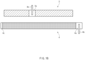
- Among them, the winding type (jelly roll type) electrode assembly is mounted in a state in which a
positive electrode 3, separators 2 (2a and 2b), and anegative electrode 4 are stacked on a core 1, and the core 1 rotates to wind thepositive electrode 3, theseparators 2, and thenegative electrode 4 around the core 1, thereby manufacturing the electrode assembly. - Here, as illustrated in
FIG. 1b that illustrates a state a state in which thepositive electrode 3 and thenegative electrode 4 are unfolded, the electrode assembly has a structure, in which thenegative electrode 4 has a negative electrode non-coatingportion 4a, on which a negative electrode active material is not applied, on a surface of a negative electrode collector at the outermost end thereof when the winding is completed, and anegative electrode tab 4b is coupled to the negative electrode non-coatingportion 4a, and also, thepositive electrode 3 has a positive electrode non-coating portion 3a, on which a positive electrode active material is not applied, on a surface of a positive electrode collector at the middle along a longitudinal direction so that apositive electrode tab 3b is spaced a predetermined distance from thenegative electrode tab 4b when the winding is completed, and thepositive electrode tab 3b is coupled to the positive electrode non-coating portion 3a. - In addition, as illustrated in
FIG. 1a that illustrates a state in which two sheets of separators are fixed first to the core, and then, the negative electrode and the positive electrode are sequentially put, theseparator 2 is put first into the core 1, and then, thenegative electrode 4, and thepositive electrode 3 are sequentially put into the core 1. That is, in the method for manufacturing the jelly roll type electrode assembly, the core 1 rotates in a state in which starting ends (an end at which the winding starts) of the two sheets ofseparators negative electrode 4 is put, and thepositive electrode 3 is put with a slight time difference. Alternatively, thenegative electrode 4, the second separator, and thepositive electrode 3 may be sequentially put while thefirst separator 2a is wound around a core 1 according to a manufacturing method. - In addition, when the core 1 rotates by a predetermined number of revolutions in the state in which the
positive electrode 3 is input, a cylindrical electrode assembly is manufactured in a wound state in the stacked state in the order of the separator/negative electrode /separator/positive electrode. - In the case of such a cylindrical electrode assembly, it is important to design the electrodes (the negative electrode and the positive electrode) in order to maximize performance and stability within a limited space.
- Particularly, in the cylindrical electrode assembly, the
positive electrode 3 and thenegative electrode 4 have different ratios in contact area between thepositive electrode 3 and thenegative electrode 4 by a curvature from the vicinity of the central hole (formed in a position from which the core is removed) to the outside, and thus, an imbalance in N/P ratio (capacity ratio in active material of the positive electrode and the negative electrode per unit area) of thepositive electrode 3 and thenegative electrode 4 occurs. The N/P ratio capable of being calculated by the following equation varies depending on the ratio in contact area between thepositive electrode 3 and thenegative electrode 4.N/P ratio = negative electrode charging capacity per unit area (mHh/cm2) X negative electrode efficiency (%)/designed capacity of positive electrode per unit area (mHh/cm2) - That is, as illustrated in
FIG. 1c that illustrates a state in which an area A in the vicinity of the central hole and an outer area B in the cylindrical electrode assembly are displayed, when the capacity of thepositive electrode 3 per unit area (capacity to accommodate electrons per unit area) is the same overall, the N/P ratio of the area A in the vicinity of the central hole may be less than 100%, but the N/P ratio of the outer area B may exceed 100%. Thus, deterioration of the electrode is accelerated on the area A in the vicinity of the central hole to have a bad influence on the lifespan of the secondary battery. -
CN 102187496A discloses a battery with a wound electrode assembly wherein a positive or a negative electrode is manufactured so that an area capacity of one surface of the electrode is different from that of the other surface of the electrode, producing the effect that in a wound state the geometrically induced variations of the N/P capacity ratio in winding direction are minimized. - Therefore, a main object of the present invention for solving the above problem is to provide an electrode assembly, in which a positive electrode capacity on an area in the vicinity of a central hole and a positive electrode capacity in an outer area are different from each other, or a positive electrode capacity on the area in the vicinity of the central hole and a positive electrode capacity in the outer area are different from each other to reduce a deviation in N/P ratio.
- The present invention for achieving the above object provides an electrode assembly, in which a positive electrode, a separator, a negative electrode are wound in a state of being stacked, wherein the positive electrode comprises a first positive electrode and a second positive electrode, each of the first positive electrode and the second positive electrode is manufactured by applying a positive electrode active material on a surface of a positive electrode collector, wherein the positive electrode active material is not applied on one end to form a positive electrode non-coating portion on which the positive electrode collector is exposed, the positive electrode non-coating portions of the first positive electrode and the second positive electrode are bonded to be connected to each other, and wherein a capacity per unit area of the first positive electrode and a capacity per unit area of the second positive electrode are different from each other.
- The positive active material applied to the first positive electrode and the positive electrode active material applied to the second positive electrode may be manufactured by mixing the same compositions, but a composition ratio of the positive electrode active material applied to the first positive electrode and a composition ratio of the positive electrode active material applied to the second positive electrode may be differently set based on an atomic ratio or mass ratio so that the capacity per unit area of the first positive electrode and the capacity per unit area of the second positive electrode are different from each other.
- An amount of positive electrode active material applied to the first positive electrode and an amount of positive electrode active material applied to the second positive electrode may be the same.
- In addition, the positive active material applied to the first positive electrode and the positive electrode active material applied to the second positive electrode may be manufactured by mixing the same compositions, but an amount of positive electrode active material applied to the first positive electrode and an amount of positive electrode active material applied to the second positive electrode may be differently set so that the capacity per unit area of the first positive electrode and the capacity per unit area of the second positive electrode are different from each other.
- The amount of positive electrode active material applied to the first positive electrode and the amount of positive electrode active material applied to the second positive electrode may have the same composition ratio based on an atomic ratio or mass ratio.
- The positive active material applied to the first positive electrode and the positive electrode active material applied to the second positive electrode may be manufactured by mixing the same compositions, but an amount of positive electrode active material applied to the first positive electrode and a composition ratio of the positive electrode active material applied to the first positive electrode are set to be different from an amount of positive electrode active material applied to the second positive electrode and a composition ratio of the positive electrode active material applied to the second positive electrode so that the capacity per unit area of the first positive electrode and the capacity per unit area of the second positive electrode are different from each other.
- Furthermore, a positive electrode tab is overlappingly bonded to a point at which the positive electrode non-coating portion of the first positive electrode and the positive electrode non-coating portion of the second positive electrode may be bonded to each other.
- Here, the positive electrode tab may have one side welded to the positive electrode non-coating portion of the first positive electrode and the other side welded to the positive electrode non-coating portion of the second positive electrode.
- The first positive electrode may be manufactured so that at least one of at least one of an amount of positive electrode active material applied to one surface of the positive electrode collector; or a composition ratio based on an atomic ratio or mass ratio of the positive electrode active material is different from that of the positive electrode active material applied to the other surface of the positive electrode collector so that a capacity per unit area on the one surface and a capacity per unit area on the other surface are different from each other.
- The second positive electrode may be manufactured so that at least one of at least one of an amount of positive electrode active material applied to one surface of the positive electrode collector; or a composition ratio based on an atomic ratio or mass ratio of the positive electrode active material is different from that of the positive electrode active material applied to the other surface of the positive electrode collector so that a capacity per unit area on the one surface and a capacity per unit area on the other surface are different from each other.
- Furthermore, the present invention further provides a structure in which the positive electrode is divided as well as the structure in which the negative electrode is divided as described above. That is, in an electrode assembly, in which a negative electrode, a separator, a positive electrode are wound in a state of being stacked, according to the present invention having the above-described technical features, the negative electrode comprises a first negative electrode and a second negative electrode, each of the first negative electrode and the second negative electrode is manufactured by applying a negative electrode active material on a surface of a negative electrode collector, wherein the negative electrode active material is not applied on one end to form a negative electrode non-coating portion on which the negative electrode collector is exposed, the negative electrode non-coating portions of the first negative electrode and the second negative electrode are bonded to be connected to each other, and wherein a capacity per unit area of the first negative electrode and a capacity per unit area of the second negative electrode are different from each other.
- The negative active material applied to the first negative electrode and the negative electrode active material applied to the second negative electrode may be manufactured by mixing the same compositions, but a composition ratio of the negative electrode active material applied to the first negative electrode and a composition ratio of the negative electrode active material applied to the second negative electrode may be differently set based on an atomic ratio or mass ratio.
- An amount of negative electrode active material applied to the first negative electrode and an amount of negative electrode active material applied to the second negative electrode may be the same.
- Alternatively, the negative active material applied to the first negative electrode and the negative electrode active material applied to the second negative electrode may be manufactured by mixing the same compositions, but an amount of negative electrode active material applied to the first negative electrode and an amount of negative electrode active material applied to the second negative electrode are differently set.
- A negative electrode tab may be overlappingly bonded to a point at which the negative electrode non-coating portion of the first negative electrode and the negative electrode non-coating portion of the second negative electrode are bonded to each other.
- The negative electrode tab may have one side welded to the negative electrode non-coating portion of the first negative electrode and the other side welded to the negative electrode non-coating portion of the second negative electrode.
- Alternatively, a negative electrode non-coating portion is additionally formed on the first negative electrode at an end opposite to the side connected to the second negative electrode, and a negative electrode non-coating portion is additionally formed on the second negative electrode at an end opposite to the side connected to the first negative electrode (like the structure according to the related art, which is illustrated in
FIG. 1b ), wherein a negative electrode tab is bonded to any one of the negative electrode non-coating portion additionally formed on the first negative electrode or the negative electrode non-coating portion additionally formed on the second negative electrode. - In addition, a secondary battery in which the electrode assembly having the above-described technical features is embedded in a case may be additionally provided.
- In the electrode assembly having the above configuration according to the present invention, since the positive electrode has the structure in which the first positive electrode and the second positive electrode are bonded to each other, the first positive electrode and the second positive electrode may be individually manufactured and thus may be determined in capacity per unit area according to whether the first and second positive electrodes are disposed at the central side or the outer side to reduce the deviation in N/P ratio when compared to the structure according to the related art.
- Here, the capacities per unit area of the first positive electrode and the second positive electrode are different from each other, and the first positive electrode and the second positive electrode have thicknesses different from each other. In addition, since the capacity per unit area of the one surface and the other surface may also be different from each other, the capacity per unit area may be adjusted according to the wound position.
- In addition, since the positive electrode tab is overlappingly bonded to the point at which the positive electrode non-coating portion of the first positive electrode and the positive electrode non-coating portion of the second positive electrode are bonded to each other, the bonding force between the first positive electrode and the second positive electrode may increase.
- In addition, since the technical features applied to the positive electrode as described above may also be equally applied to the negative electrode, there may be the effect of flexibly determining whether the technical features are applied to the positive electrode or the negative electrode according to the manufacturing conditions.
-
-
FIG. 1a is a view illustrating a state in which two sheets of separators are fixed first to a core, and then, a negative electrode and a positive electrode are sequentially put. -
FIG. 1b is a view illustrating a state in which the positive electrode and the negative electrode, which are put as illustrated inFIG. 1a , according to the related art are unfolded. -
FIG. 1c is a view illustrating a state in which an area A in the vicinity of a central hole and an outer area B in a cylindrical electrode assembly are disposed. -
FIG. 2 is a view illustrating a state in which a positive electrode and a negative electrode are unfolded, wherein the positive electrode is configured so that a first positive electrode and a second positive electrode are bonded to each other. -
FIG. 3 is a view illustrating a state in which a positive electrode tab is additionally bonded to a point at which the first positive electrode and the second positive electrode are bonded to each other after the first positive electrode and the second positive electrode are bonded to each other. -
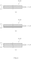
FIG. 4 is a cross-sectional view (a) illustrating a state in which a positive electrode active material having the same composition ratio is applied on both surfaces of the first positive electrode and the second positive electrode, a cross-sectional view (b) illustrating positive electrode active materials having different composition ratios are applied on one surface and the other surface, respectively, and a cross-sectional view (c) illustrating a state in which a positive electrode active material having the same composition ratio is applied in different amounts on both side surfaces. -
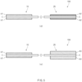
FIG. 5 is a view illustrating a state (d) before the first positive electrode and the second positive electrode, to which positive electrode active materials having different composition ratios are applied, respectively, are bonded to each other and a state (e) before the first positive electrode and the second positive electrode, to which a positive electrode active material having the same composition ratio is applied in different amounts, are bonded to each other. -
FIG. 6 is a view illustrating a state in which the positive electrode and the negative electrode are unfolded, wherein the negative electrode is configured so that a first negative electrode and a second negative electrode are bonded to each other. -
FIG. 7 is a view illustrating a state in which a negative electrode tab is additionally bonded to a point at which the first negative electrode and the second negative electrode are bonded to each other after the first negative electrode and the second negative electrode are bonded to each other. - Hereinafter, preferred embodiments of the present invention will be described in detail with reference to the accompanying drawings in such a manner that the technical idea of the present invention may easily be carried out by a person with ordinary skill in the art to which the invention pertains.
- In order to clearly describe the present invention, parts irrelevant to the description are omitted, and the same reference numerals are assigned to the same or similar components throughout the specification.
- Also, terms or words used in this specification and claims should not be restrictively interpreted as ordinary meanings or dictionary-based meanings, but should be interpreted as meanings and concepts conforming to the scope of the present invention on the basis of the principle that an inventor can properly define the concept of a term to describe and explain his or her invention in the best ways.
- The present invention relates to an electrode assembly, in which a first
positive electrode 10 and a secondpositive electrode 20, which have different capacities per unit area to suppress or at least alleviate the problem of occurrence of a deviation in N/P ratio between an area in the vicinity of a central hole and an outer area, and an electrode assembly, in which a firstnegative electrode 40 and a secondnegative electrode 50 are bonded to form anegative electrode 200. Hereinafter, the present invention will be described in more detail with reference to the accompanying drawings. -
FIG. 2 is a view illustrating a state in which apositive electrode 100 and anegative electrode 200 are unfolded, wherein thepositive electrode 100 is configured so that a firstpositive electrode 10 and a secondpositive electrode 20 are bonded to each other, andFIG. 3 is a view illustrating a state in which apositive electrode tab 30 is additionally bonded to a point at which the firstpositive electrode 10 and the secondpositive electrode 20 are bonded to each other after the firstpositive electrode 10 and the secondpositive electrode 20 are bonded to each other. - Referring to
FIGS. 2 and3 , an electrode assembly of the present invention is an electrode assembly manufactured by winding a separator, thenegative electrode 200, a separator, and thepositive electrode 100, which are in a stacked state. When starting ends of two sheets of separators are wound around a core, thenegative electrode 200 and thepositive electrode 100 are sequentially put to manufacture the electrode assembly. - Here, in the electrode assembly according to the present invention, the
positive electrode 100 is configured so that the firstpositive electrode 10 and the secondpositive electrode 20, which have different capacities per unit area, are bonded to each other. - That is, the first
positive electrode 10 is manufactured by applying a positive electrode active material on a surface of a positive electrode collector, and the secondpositive electrode 20 is also manufactured by applying the positive electrode active material on a surface of a positive electrode collector. - In addition, each of the first
positive electrode 10 and the secondpositive electrode 20 has a structure in which positive electrodenon-coating portions non-coating portions positive electrode 20 are bonded to each other through welding or a conductive adhesive. - Furthermore, a
positive electrode tab 30 is overlappingly bonded to a point at which the positive electrodenon-coating portion 11 of the firstpositive electrode 10 and the positive electrodenon-coating portion 21 of the secondpositive electrode 20 are bonded to each other. In more detail, thepositive electrode tab 30 is bonded so that one side thereof is welded to the positive electrodenon-coating portion 11 of the firstpositive electrode 10, and the other side thereof is welded to the positive electrodenon-coating portion 21 of the secondpositive electrode 20. Thus, thepositive electrode tab 30 may allow the firstpositive electrode 10 and the secondpositive electrode 20 to increase in bonding force therebetween. -
FIG. 4 is a cross-sectional view (a) illustrating a state in which a positive electrode active material having the same composition ratio is applied on both surfaces of the firstpositive electrode 10 and the secondpositive electrode 20, a cross-sectional view (b) illustrating positive electrode active materials having different composition ratios are applied on one surface and the other surface, respectively, and a cross-sectional view (c) illustrating a state in which a positive electrode active material having the same composition ratio is applied in different amounts on both side surfaces. - As illustrated in (a) of
FIG. 4 , the firstpositive electrode 10 and the secondpositive electrode 20 may be applied so that a positive electrode active material A1 having the same composition ratio has the same thickness on one side and the other side of a positive electrode collector C. - Also, as illustrated in (b) of
FIG. 4 , a positive electrode active material A2, which is composed of a different composition ratio by increasing or decreasing in content of a specific composition related to stability or capacity so as to be different from the composition ratio of the positive electrode active material A1 applied to the one surface, may be applied to the other surface of the positive electrode collector C so that capacities per unit area of both surfaces are different from each other. - Alternatively, as illustrated in (c) of
FIG. 4 , the positive electrode active materials A1 and A3 having the same composition ratio may be applied to both surfaces, but the capacities per unit area may be different from each other by a more amount of positive electrode active material on the other surface than that of the positive electrode active material applied on the one surface. - That is, in the present invention, all of the first
positive electrode 10 and the secondpositive electrode 20 or any one of the firstpositive electrode 10 and the secondpositive electrode 20 may be manufactured so that at least one of the amount of positive electrode active material A1 applied to the one surface of the positive electrode collector C; or a composition ratio based on an atomic ratio or mass ratio of the positive electrode active material A1 is different from that of each of the positive electrode active materials A2 and A3 applied to the other surface of the positive electrode collector C. As a result, the capacity per unit area on the one surface and the capacity per unit area on the other surface may be different from each other. - Therefore, the present invention provides embodiments in which capacities per unit area of the first
positive electrode 10 and the secondpositive electrode 20 are differently formed by combining the above characteristics. -
FIG. 5 is a view illustrating a state (d) before the firstpositive electrode 10 and the secondpositive electrode 20, to which positive electrode active materials having different composition ratios are applied, respectively, are bonded to each other and a state (e) before the firstpositive electrode 10 and the secondpositive electrode 20, to which a positive electrode active material having the same composition ratio is applied in different amounts, are bonded to each other. - In this embodiment, the positive electrode active material A1 applied to the first
positive electrode 10 and the positive electrode active material A2 applied to the secondpositive electrode 20 are manufactured by mixing the same compositions, but a composition ratio of the positive electrode active material A1 applied to the firstpositive electrode 10 and a composition ratio of the positive electrode active material A2 applied to the secondpositive electrode 20, based on an atomic ratio or mass ratio, are set to be different from each other, and thus, the capacity per unit area of the firstpositive electrode 10 and the capacity per unit area of the secondpositive electrode 20 may be different from each other. - That is, as illustrated in (d) of
FIG. 5 , the composition ratio of the positive electrode active material applied to the positive electrode collector C may vary, and thus, the capacities per unit area of the firstpositive electrode 10 and the secondpositive electrode 20 may be different from each other. - Here, the positive active material A1 applied to the first
positive electrode 10 and the positive electrode active material A2 applied to the secondpositive electrode 20 may be applied in the same amount (may have the same thickness). - In addition, as illustrated (e) of
FIG. 5 , a positive electrode active material A1 applied to the firstpositive electrode 10 and a positive electrode active material A3 applied to the secondpositive electrode 20 are manufactured by mixing the same compositions, but an amount of positive electrode active material A1 applied to the firstpositive electrode 10 and an amount of positive electrode active material A3 applied to the secondpositive electrode 20, are set to be different from each other, and thus, the capacity per unit area of the firstpositive electrode 10 and the capacity per unit area of the secondpositive electrode 20 may be different from each other. - Here, the positive electrode active material A1 applied to the first
positive electrode 10 and the positive electrode active material A2 applied to the secondpositive electrode 20 may be manufactured to have the same composition ratio based on an atomic ratio or mass ratio. - Alternatively, the positive active material applied to the first
positive electrode 10 and the positive electrode active material applied to the secondpositive electrode 20 are manufactured by mixing the same compositions according to a combination of the first embodiment and the second embodiment, but an amount of positive electrode active material applied to the first positive electrode; and a composition ratio based on an atomic ratio or mass ratio of the positive electrode active material may be set to be different from an amount of positive electrode active material applied to the secondpositive electrode 20 and a composition ratio based on an atomic ratio or mass ratio of the positive electrode active material. As a result, the capacity per unit area of the firstpositive electrode 10 and the capacity per unit area of the secondpositive electrode 20 may be different from each other. - Furthermore, although only the connection structure of the first
positive electrode 10 and the secondpositive electrode 20 having different capacities per unit area has been described in the present invention, a positive electrodenon-coating portion 21 may be additionally formed at an opposite end of the secondpositive electrode 20, and then, a third positive electrode and a fourth positive electrode, each of which has the positive electrode non-coating portion, may be sequentially connected. In this case, a capacity per unit area of each of the additionally connected third and fourth electrodes may be different from that of each of the first and second electrodes. - As described above, in the electrode assembly according to the present invention, the configuration applied to the positive electrode may be equally applied to the negative electrode.
-
FIG. 6 is a view illustrating a state in which the positive electrode and the negative electrode are unfolded, wherein thenegative electrode 200 is configured so that a firstnegative electrode 40 and a secondnegative electrode 50 are bonded to each other, andFIG. 7 is a view illustrating a state in which a negative electrode tab is additionally bonded to a point at which the firstnegative electrode 40 and the secondnegative electrode 50 are bonded to each other after the firstnegative electrode 40 and the secondnegative electrode 50 are bonded to each other. - Referring to
FIGS. 6 and 8, an electrode assembly having a structure, in which two negative electrodes are connected to each other, according to the present invention is an electrode assembly manufactured by winding a separator, thenegative electrode 200, a separator, and thepositive electrode 100, which are in a stacked state. When starting ends of two sheets of separators are wound around a core, thenegative electrode 200 and thepositive electrode 100 are sequentially put to manufacture the electrode assembly. - Here, in the electrode assembly according to the present invention, the
negative electrode 200 is configured so that the firstnegative electrode 40 and the secondnegative electrode 50, which have different capacities per unit area, are bonded to each other. - That is, like the above-described structure of the positive electrode, the first
negative electrode 40 is manufactured by applying a negative electrode active material on a surface of a negative electrode collector, and the secondnegative electrode 50 is also manufactured by applying the negative electrode active material on a surface of a negative electrode collector. - In addition, each of the first
negative electrode 40 and the secondnegative electrode 50 has a structure in which negative electrodenon-coating portions non-coating portions negative electrode 50 are bonded to each other through welding or a conductive adhesive. - Furthermore, a
negative electrode tab 60 is overlappingly bonded to a point at which the negativeelectrode non-coating portion 41 of the firstnegative electrode 40 and the negativeelectrode non-coating portion 51 of the secondnegative electrode 50 are bonded to each other. In more detail, thenegative electrode tab 60 is bonded so that one side thereof is welded to the negativeelectrode non-coating portion 41 of the firstnegative electrode 40, and the other side thereof is welded to the negativeelectrode non-coating portion 51 of the secondnegative electrode 50. Thus, thenegative electrode tab 60 may allow the firstnegative electrode 40 and the secondnegative electrode 50 to increase in bonding force therebetween. - For reference, like the structure (the structure illustrated in
FIG. 1b ) according to the related art, thenegative electrode tab 60 may be bonded to one end of the negative electrode. That is, a negativeelectrode non-coating portion 42 may be additionally formed on the firstnegative electrode 40 at an end opposite to the side connected to the secondnegative electrode 50, and a negativeelectrode non-coating portion 52 may be additionally formed on the secondnegative electrode 50 at an end opposite to the side connected to the firstnegative electrode 40. In addition, the electrode assembly may have a structure, in which thenegative electrode tab 60 is bonded to any one of the negativeelectrode non-coating portion 42 additionally formed on the firstnegative electrode 40 or the negativeelectrode non-coating portion 52 additionally formed on the secondnegative electrode 50. - Furthermore, like the above-described structure of the positive electrode, each of the first
negative electrode 40 and the secondnegative electrode 50 may have a structure in which a negative active material having the same composition ratio is applied at the same thickness to one side and the other side of the negative electrode collector. - In addition, a positive electrode active material, which is composed of a different composition ratio by increasing or decreasing in content of a specific composition related to stability or capacity so as to be different from the composition ratio of the positive electrode active material applied to the one surface, may be applied to the other surface of the positive electrode collector so that capacities per unit area of both surfaces are different from each other.
- Alternatively, the positive electrode active materials having the same composition ratio may be applied to both surfaces of the negative electrode collector, but the capacities per unit area may be different from each other by a more amount of positive electrode active material on the other surface than that of the positive electrode active material applied on the one surface.
- That is, all of the first
negative electrode 40 and the secondnegative electrode 50 or any one of the firstnegative electrode 40 and the secondnegative electrode 50 may be manufactured so that at least one of the amount of negative electrode active material applied to the one surface of the negative electrode collector; or a composition ratio based on an atomic ratio or mass ratio of the negative electrode active material is different from that of each of the negative electrode active materials applied to the other surface of the negative electrode collector. As a result, the capacity per unit area on the one surface and the capacity per unit area on the other surface may be different from each other. - Therefore, in the present invention, the capacities per unit area of the first
negative electrode 40 and the secondnegative electrode 50 may be differently formed in the same manner as in the configuration in which the capacities per unit area of the firstpositive electrode 10 and the secondpositive electrode 20 are differently formed by combining the above features. - Furthermore, a configuration in which the negative electrode non-coating portion is additionally formed at the opposite end of the second
negative electrode 50, and the third and fourth negative electrode, each of which has the negative electrode non-coating portion, are sequentially connected, may also be possible. Here, each of the third negative electrode and the fourth negative electrode, which are connected additionally, may also have a different capacity from that of each of the first and second negative electrodes. - In the electrode assembly having the above configuration according to the present invention, since the
positive electrode 100 has the structure in which the firstpositive electrode 10 and the secondpositive electrode 20 are bonded to each other, or thenegative electrode 200 has the structure in which the firstnegative electrode 40 and the secondnegative electrode 50 are bonded to each other, each of thepositive electrode 100 and thenegative electrode 200 may be determined in capacity per unit area according to whether the first and second positive electrodes or the first and second negative electrodes are disposed at the central side or the outer side to reduce the deviation in N/P ratio when compared to the structure according to the related art. - Here, the capacities per unit area of the first
positive electrode 10 and the secondpositive electrode 20 or the firstnegative electrode 40 and the secondnegative electrode 50 may be different from each other, and the first positive electrode and the second positive electrode or the firstnegative electrode 40 and the secondnegative electrode 50 have thicknesses different from each other. In addition, since the capacity per unit area of the one surface and the other surface may also be different from each other, the capacity per unit area may be adjusted according to the wound position. - In addition, since the
positive electrode tab 30 may be overlappingly bonded to the point at which the positive electrodenon-coating portion 21 of the firstpositive electrode 10 and the positive electrodenon-coating portion 21 of the secondpositive electrode 20 are bonded to each other, or thenegative electrode tab 60 may be overlappingly bonded to the point at which the negativeelectrode non-coating portion 41 of the firstnegative electrode 40 and the negativeelectrode non-coating portion 51 of the secondnegative electrode 50 are bonded to each other, the bonding force between the first positive electrode and the second positive electrode or between the first negative electrode and the second negative electrode may increase. - In addition, in the present invention, a secondary battery, in which the electrode assembly as described above is embedded in the case, may be provided.
-
- 10: First positive electrode
- 20: Second positive electrode
- 30: Positive electrode tab
- 40: First negative electrode
- 50: Second negative electrode
- 60: Negative electrode tab
- 100: Positive electrode
- 200: Negative electrode
Claims (14)
- An electrode assembly, in which a positive electrode, a separator, a negative electrode are wound in a state of being stacked,wherein the positive electrode comprises a first positive electrode and a second positive electrode,each of the first positive electrode and the second positive electrode is manufactured by applying a positive electrode active material on a surface of a positive electrode collector, wherein the positive electrode active material is not applied on one end to form a positive electrode non-coating portion on which the positive electrode collector is exposed,the positive electrode non-coating portions of the first positive electrode and the second positive electrode are bonded to be connected to each other, andwherein a capacity per unit area of the first positive electrode and a capacity per unit area of the second positive electrode are different from each other.
- The electrode assembly of claim 1, wherein the positive active material applied to the first positive electrode and the positive electrode active material applied to the second positive electrode are manufactured by mixing the same compositions, but a composition ratio of the positive electrode active material applied to the first positive electrode and a composition ratio of the positive electrode active material applied to the second positive electrode are differently set based on an atomic ratio or mass ratio so that the capacity per unit area of the first positive electrode and the capacity per unit area of the second positive electrode are different from each other.
- The electrode assembly of claim 2, wherein an amount of positive electrode active material applied to the first positive electrode and an amount of positive electrode active material applied to the second positive electrode are the same.
- The electrode assembly of claim 1, wherein the positive active material applied to the first positive electrode and the positive electrode active material applied to the second positive electrode are manufactured by mixing the same compositions, but an amount of positive electrode active material applied to the first positive electrode and an amount of positive electrode active material applied to the second positive electrode are differently set so that the capacity per unit area of the first positive electrode and the capacity per unit area of the second positive electrode are different from each other.
- The electrode assembly of claim 4, wherein the amount of positive electrode active material applied to the first positive electrode and the amount of positive electrode active material applied to the second positive electrode have the same composition ratio based on an atomic ratio or mass ratio.
- The electrode assembly of claim 1, wherein the positive active material applied to the first positive electrode and the positive electrode active material applied to the second positive electrode are manufactured by mixing the same compositions, but an amount of positive electrode active material applied to the first positive electrode and a composition ratio of the positive electrode active material applied to the first positive electrode are set to be different from an amount of positive electrode active material applied to the second positive electrode and a composition ratio of the positive electrode active material applied to the second positive electrode so that the capacity per unit area of the first positive electrode and the capacity per unit area of the second positive electrode are different from each other.
- The electrode assembly of claim 1, wherein a positive electrode tab is overlappingly bonded to a point at which the positive electrode non-coating portion of the first positive electrode and the positive electrode non-coating portion of the second positive electrode are bonded to each other.
- The electrode assembly of claim 7, wherein the positive electrode tab has one side welded to the positive electrode non-coating portion of the first positive electrode and the other side welded to the positive electrode non-coating portion of the second positive electrode.
- The electrode assembly of claim 1, wherein the first positive electrode is manufactured so that at least one of at least one of an amount of positive electrode active material applied to one surface of the positive electrode collector; or a composition ratio based on an atomic ratio or mass ratio of the positive electrode active material is different from that of the positive electrode active material applied to the other surface of the positive electrode collector so that a capacity per unit area on the one surface and a capacity per unit area on the other surface are different from each other.
- The electrode assembly of claim 1, wherein the second positive electrode is manufactured so that at least one of at least one of an amount of positive electrode active material applied to one surface of the positive electrode collector; or a composition ratio based on an atomic ratio or mass ratio of the positive electrode active material is different from that of the positive electrode active material applied to the other surface of the positive electrode collector so that a capacity per unit area on the one surface and a capacity per unit area on the other surface are different from each other.
- An electrode assembly, in which a negative electrode, a separator, a positive electrode are wound in a state of being stacked,wherein the negative electrode comprises a first negative electrode and a second negative electrode,each of the first negative electrode and the second negative electrode is manufactured by applying a negative electrode active material on a surface of a negative electrode collector, wherein the negative electrode active material is not applied on one end to form a negative electrode non-coating portion on which the negative electrode collector is exposed,the negative electrode non-coating portions of the first negative electrode and the second negative electrode are bonded to be connected to each other, andwherein a capacity per unit area of the first negative electrode and a capacity per unit area of the second negative electrode are different from each other.
- The electrode assembly of claim 11, wherein the negative active material applied to the first negative electrode and the negative electrode active material applied to the second negative electrode are manufactured by mixing the same compositions, but a composition ratio of the negative electrode active material applied to the first negative electrode and a composition ratio of the negative electrode active material applied to the second negative electrode are differently set based on an atomic ratio or mass ratio.
- The electrode assembly of claim 11, wherein an amount of negative electrode active material applied to the first negative electrode and an amount of negative electrode active material applied to the second negative electrode are the same.
- The electrode assembly of claim 11, wherein the negative active material applied to the first negative electrode and the negative electrode active material applied to the second negative electrode are manufactured by mixing the same compositions, but an amount of negative electrode active material applied to the first negative electrode and an amount of negative electrode active material applied to the second negative electrode are differently set.
Applications Claiming Priority (3)
| Application Number | Priority Date | Filing Date | Title |
|---|---|---|---|
| KR20200088408 | 2020-07-16 | ||
| KR1020210093046A KR102816048B1 (en) | 2020-07-16 | 2021-07-15 | Electrode assembly |
| PCT/KR2021/009173 WO2022015101A1 (en) | 2020-07-16 | 2021-07-16 | Electrode assembly |
Publications (3)
| Publication Number | Publication Date |
|---|---|
| EP4184629A1 EP4184629A1 (en) | 2023-05-24 |
| EP4184629A4 EP4184629A4 (en) | 2024-05-01 |
| EP4184629B1 true EP4184629B1 (en) | 2025-04-09 |
Family
ID=79554852
Family Applications (1)
| Application Number | Title | Priority Date | Filing Date |
|---|---|---|---|
| EP21841678.2A Active EP4184629B1 (en) | 2020-07-16 | 2021-07-16 | Electrode assembly |
Country Status (6)
| Country | Link |
|---|---|
| US (1) | US12476335B2 (en) |
| EP (1) | EP4184629B1 (en) |
| CN (1) | CN115803924A (en) |
| ES (1) | ES3032436T3 (en) |
| HU (1) | HUE071309T2 (en) |
| WO (1) | WO2022015101A1 (en) |
Family Cites Families (16)
| Publication number | Priority date | Publication date | Assignee | Title |
|---|---|---|---|---|
| JP2001236983A (en) | 2000-02-25 | 2001-08-31 | Sanoh Industrial Co Ltd | Wound electrode for battery |
| KR100496294B1 (en) * | 2002-12-28 | 2005-06-17 | 삼성에스디아이 주식회사 | Electrode unit and second battery using the same |
| KR100515833B1 (en) * | 2003-05-26 | 2005-09-21 | 삼성에스디아이 주식회사 | Jelly-roll type electrode assembly and secondary battery applying the same |
| KR20080037867A (en) * | 2006-10-27 | 2008-05-02 | 삼성에스디아이 주식회사 | Electrode assembly and manufacturing method of lithium secondary battery and lithium secondary battery using same |
| KR100963981B1 (en) | 2007-03-26 | 2010-06-15 | 주식회사 엘지화학 | Jelly-rolls containing active material layers with different loadings |
| JP2008262777A (en) | 2007-04-11 | 2008-10-30 | Sony Corp | Secondary battery |
| JPWO2011052126A1 (en) | 2009-10-28 | 2013-03-14 | パナソニック株式会社 | Electrode, secondary battery, and method for manufacturing secondary battery |
| JP2011204660A (en) | 2010-03-04 | 2011-10-13 | Sanyo Electric Co Ltd | Lithium secondary battery |
| KR20120060537A (en) | 2010-12-02 | 2012-06-12 | 현대자동차주식회사 | Jelly-Roll type electrode assembly |
| EP2757624A4 (en) | 2011-09-14 | 2015-04-22 | Gs Yuasa Int Ltd | CYLINDRICAL BATTERY |
| KR101637890B1 (en) * | 2013-05-30 | 2016-07-08 | 주식회사 엘지화학 | A Secondary Battery having Two More anode Taps |
| JP2015088272A (en) * | 2013-10-29 | 2015-05-07 | トヨタ自動車株式会社 | Non-aqueous electrolyte secondary battery and manufacturing method thereof |
| KR101639209B1 (en) | 2013-10-30 | 2016-07-13 | 주식회사 엘지화학 | A Cell Assembly with Improved Jelly-Roll Type Structure and A Secondary Battery Comprising the Same |
| KR102502194B1 (en) * | 2015-10-27 | 2023-02-20 | 삼성에스디아이 주식회사 | Rechargeable battery having electrode tap and fabricating method thereof |
| KR102239364B1 (en) * | 2017-06-27 | 2021-04-09 | 주식회사 엘지화학 | Lithium secondary battery including cylindrical-jelly roll |
| KR102557413B1 (en) | 2018-04-25 | 2023-07-18 | 주식회사 엘지에너지솔루션 | Manufacturing method for lithium metal electrode |
-
2021
- 2021-07-16 HU HUE21841678A patent/HUE071309T2/en unknown
- 2021-07-16 US US18/014,689 patent/US12476335B2/en active Active
- 2021-07-16 WO PCT/KR2021/009173 patent/WO2022015101A1/en not_active Ceased
- 2021-07-16 ES ES21841678T patent/ES3032436T3/en active Active
- 2021-07-16 CN CN202180045163.XA patent/CN115803924A/en active Pending
- 2021-07-16 EP EP21841678.2A patent/EP4184629B1/en active Active
Also Published As
| Publication number | Publication date |
|---|---|
| US20230275329A1 (en) | 2023-08-31 |
| CN115803924A (en) | 2023-03-14 |
| EP4184629A4 (en) | 2024-05-01 |
| WO2022015101A1 (en) | 2022-01-20 |
| US12476335B2 (en) | 2025-11-18 |
| HUE071309T2 (en) | 2025-08-28 |
| ES3032436T3 (en) | 2025-07-18 |
| EP4184629A1 (en) | 2023-05-24 |
Similar Documents
| Publication | Publication Date | Title |
|---|---|---|
| US20250385292A1 (en) | Secondary Battery and Method for Manufacturing the Same | |
| EP4270565A1 (en) | Electrode assembly and secondary battery comprising same | |
| EP3849005A1 (en) | Secondary battery | |
| KR100731452B1 (en) | Pole plate winding device and winding method of cylindrical battery | |
| US20100319187A1 (en) | Manufacturing Method of Stacked Electrodes By Winding Type Electrode Stacking and Stacked Electrode Thereby | |
| CN113767504B (en) | Electrode assembly and method for manufacturing the same | |
| EP4343954A1 (en) | Electrode tab and method for cutting electrode tab | |
| EP3598555B1 (en) | Electrode, electrode assembly and method for manufacturing the same | |
| EP4184629B1 (en) | Electrode assembly | |
| EP4589700A1 (en) | Electrode assembly | |
| EP3780237A1 (en) | Unit cell and manufacturing method therefor | |
| KR102816048B1 (en) | Electrode assembly | |
| JPH0574496A (en) | Secondary battery | |
| US12300777B2 (en) | Electrode assembly and method for manufacturing same | |
| KR20240056427A (en) | Elctrode assembly and electrochemical device comprising the same | |
| KR20210017086A (en) | Electrode-assembly and manufacturing method thereof | |
| EP4164028B1 (en) | Electrode assembly and secondary battery comprising the same | |
| EP4589715A1 (en) | Electrode assembly | |
| KR102837704B1 (en) | Elctrode assembly and electrochemical device comprising the same | |
| EP4700878A1 (en) | Ectrode assembly and secondary battery including the same | |
| KR102340101B1 (en) | Battery and method for manufcturing the same | |
| KR20240056431A (en) | Elctrode assembly and electrochemical device comprising the same | |
| JP2025520613A (en) | Electrode assembly and electrochemical device including the same |
Legal Events
| Date | Code | Title | Description |
|---|---|---|---|
| STAA | Information on the status of an ep patent application or granted ep patent |
Free format text: STATUS: THE INTERNATIONAL PUBLICATION HAS BEEN MADE |
|
| PUAI | Public reference made under article 153(3) epc to a published international application that has entered the european phase |
Free format text: ORIGINAL CODE: 0009012 |
|
| STAA | Information on the status of an ep patent application or granted ep patent |
Free format text: STATUS: REQUEST FOR EXAMINATION WAS MADE |
|
| 17P | Request for examination filed |
Effective date: 20221222 |
|
| AK | Designated contracting states |
Kind code of ref document: A1 Designated state(s): AL AT BE BG CH CY CZ DE DK EE ES FI FR GB GR HR HU IE IS IT LI LT LU LV MC MK MT NL NO PL PT RO RS SE SI SK SM TR |
|
| DAV | Request for validation of the european patent (deleted) | ||
| DAX | Request for extension of the european patent (deleted) | ||
| REG | Reference to a national code |
Ref country code: DE Ref legal event code: R079 Ipc: H01M0004139000 Ref country code: DE Ref legal event code: R079 Ref document number: 602021029038 Country of ref document: DE Free format text: PREVIOUS MAIN CLASS: H01M0010040000 Ipc: H01M0004139000 |
|
| A4 | Supplementary search report drawn up and despatched |
Effective date: 20240403 |
|
| RIC1 | Information provided on ipc code assigned before grant |
Ipc: H01M 10/0587 20100101ALI20240326BHEP Ipc: H01M 50/536 20210101ALI20240326BHEP Ipc: H01M 10/04 20060101ALI20240326BHEP Ipc: H01M 4/139 20100101AFI20240326BHEP |
|
| GRAP | Despatch of communication of intention to grant a patent |
Free format text: ORIGINAL CODE: EPIDOSNIGR1 |
|
| STAA | Information on the status of an ep patent application or granted ep patent |
Free format text: STATUS: GRANT OF PATENT IS INTENDED |
|
| GRAS | Grant fee paid |
Free format text: ORIGINAL CODE: EPIDOSNIGR3 |
|
| INTG | Intention to grant announced |
Effective date: 20250131 |
|
| GRAA | (expected) grant |
Free format text: ORIGINAL CODE: 0009210 |
|
| STAA | Information on the status of an ep patent application or granted ep patent |
Free format text: STATUS: THE PATENT HAS BEEN GRANTED |
|
| AK | Designated contracting states |
Kind code of ref document: B1 Designated state(s): AL AT BE BG CH CY CZ DE DK EE ES FI FR GB GR HR HU IE IS IT LI LT LU LV MC MK MT NL NO PL PT RO RS SE SI SK SM TR |
|
| P01 | Opt-out of the competence of the unified patent court (upc) registered |
Free format text: CASE NUMBER: APP_10245/2025 Effective date: 20250228 |
|
| REG | Reference to a national code |
Ref country code: GB Ref legal event code: FG4D |
|
| REG | Reference to a national code |
Ref country code: CH Ref legal event code: EP |
|
| REG | Reference to a national code |
Ref country code: DE Ref legal event code: R096 Ref document number: 602021029038 Country of ref document: DE |
|
| REG | Reference to a national code |
Ref country code: IE Ref legal event code: FG4D |
|
| PGFP | Annual fee paid to national office [announced via postgrant information from national office to epo] |
Ref country code: GB Payment date: 20250624 Year of fee payment: 5 |
|
| PGFP | Annual fee paid to national office [announced via postgrant information from national office to epo] |
Ref country code: BE Payment date: 20250623 Year of fee payment: 5 |
|
| PGFP | Annual fee paid to national office [announced via postgrant information from national office to epo] |
Ref country code: FR Payment date: 20250624 Year of fee payment: 5 |
|
| REG | Reference to a national code |
Ref country code: ES Ref legal event code: FG2A Ref document number: 3032436 Country of ref document: ES Kind code of ref document: T3 Effective date: 20250718 |
|
| PGFP | Annual fee paid to national office [announced via postgrant information from national office to epo] |
Ref country code: HU Payment date: 20250721 Year of fee payment: 5 |
|
| REG | Reference to a national code |
Ref country code: NL Ref legal event code: MP Effective date: 20250409 |
|
| REG | Reference to a national code |
Ref country code: HU Ref legal event code: AG4A Ref document number: E071309 Country of ref document: HU |
|
| PG25 | Lapsed in a contracting state [announced via postgrant information from national office to epo] |
Ref country code: NL Free format text: LAPSE BECAUSE OF FAILURE TO SUBMIT A TRANSLATION OF THE DESCRIPTION OR TO PAY THE FEE WITHIN THE PRESCRIBED TIME-LIMIT Effective date: 20250409 |
|
| REG | Reference to a national code |
Ref country code: AT Ref legal event code: MK05 Ref document number: 1784390 Country of ref document: AT Kind code of ref document: T Effective date: 20250409 |
|
| PG25 | Lapsed in a contracting state [announced via postgrant information from national office to epo] |
Ref country code: FI Free format text: LAPSE BECAUSE OF FAILURE TO SUBMIT A TRANSLATION OF THE DESCRIPTION OR TO PAY THE FEE WITHIN THE PRESCRIBED TIME-LIMIT Effective date: 20250409 Ref country code: PT Free format text: LAPSE BECAUSE OF FAILURE TO SUBMIT A TRANSLATION OF THE DESCRIPTION OR TO PAY THE FEE WITHIN THE PRESCRIBED TIME-LIMIT Effective date: 20250811 |
|
| PGFP | Annual fee paid to national office [announced via postgrant information from national office to epo] |
Ref country code: ES Payment date: 20250822 Year of fee payment: 5 |
|
| PGFP | Annual fee paid to national office [announced via postgrant information from national office to epo] |
Ref country code: DE Payment date: 20250624 Year of fee payment: 5 |
|
| REG | Reference to a national code |
Ref country code: LT Ref legal event code: MG9D |
|
| PG25 | Lapsed in a contracting state [announced via postgrant information from national office to epo] |
Ref country code: NO Free format text: LAPSE BECAUSE OF FAILURE TO SUBMIT A TRANSLATION OF THE DESCRIPTION OR TO PAY THE FEE WITHIN THE PRESCRIBED TIME-LIMIT Effective date: 20250709 Ref country code: GR Free format text: LAPSE BECAUSE OF FAILURE TO SUBMIT A TRANSLATION OF THE DESCRIPTION OR TO PAY THE FEE WITHIN THE PRESCRIBED TIME-LIMIT Effective date: 20250710 |
|
| PG25 | Lapsed in a contracting state [announced via postgrant information from national office to epo] |
Ref country code: PL Free format text: LAPSE BECAUSE OF FAILURE TO SUBMIT A TRANSLATION OF THE DESCRIPTION OR TO PAY THE FEE WITHIN THE PRESCRIBED TIME-LIMIT Effective date: 20250409 |
|
| PG25 | Lapsed in a contracting state [announced via postgrant information from national office to epo] |
Ref country code: BG Free format text: LAPSE BECAUSE OF FAILURE TO SUBMIT A TRANSLATION OF THE DESCRIPTION OR TO PAY THE FEE WITHIN THE PRESCRIBED TIME-LIMIT Effective date: 20250409 |
|
| PG25 | Lapsed in a contracting state [announced via postgrant information from national office to epo] |
Ref country code: HR Free format text: LAPSE BECAUSE OF FAILURE TO SUBMIT A TRANSLATION OF THE DESCRIPTION OR TO PAY THE FEE WITHIN THE PRESCRIBED TIME-LIMIT Effective date: 20250409 |
|
| PG25 | Lapsed in a contracting state [announced via postgrant information from national office to epo] |
Ref country code: AT Free format text: LAPSE BECAUSE OF FAILURE TO SUBMIT A TRANSLATION OF THE DESCRIPTION OR TO PAY THE FEE WITHIN THE PRESCRIBED TIME-LIMIT Effective date: 20250409 |
|
| PG25 | Lapsed in a contracting state [announced via postgrant information from national office to epo] |
Ref country code: RS Free format text: LAPSE BECAUSE OF FAILURE TO SUBMIT A TRANSLATION OF THE DESCRIPTION OR TO PAY THE FEE WITHIN THE PRESCRIBED TIME-LIMIT Effective date: 20250709 |
|
| PG25 | Lapsed in a contracting state [announced via postgrant information from national office to epo] |
Ref country code: IS Free format text: LAPSE BECAUSE OF FAILURE TO SUBMIT A TRANSLATION OF THE DESCRIPTION OR TO PAY THE FEE WITHIN THE PRESCRIBED TIME-LIMIT Effective date: 20250809 |
|
| PG25 | Lapsed in a contracting state [announced via postgrant information from national office to epo] |
Ref country code: LV Free format text: LAPSE BECAUSE OF FAILURE TO SUBMIT A TRANSLATION OF THE DESCRIPTION OR TO PAY THE FEE WITHIN THE PRESCRIBED TIME-LIMIT Effective date: 20250409 |
|
| REG | Reference to a national code |
Ref country code: DE Ref legal event code: R097 Ref document number: 602021029038 Country of ref document: DE |
|
| PG25 | Lapsed in a contracting state [announced via postgrant information from national office to epo] |
Ref country code: SM Free format text: LAPSE BECAUSE OF FAILURE TO SUBMIT A TRANSLATION OF THE DESCRIPTION OR TO PAY THE FEE WITHIN THE PRESCRIBED TIME-LIMIT Effective date: 20250409 Ref country code: DK Free format text: LAPSE BECAUSE OF FAILURE TO SUBMIT A TRANSLATION OF THE DESCRIPTION OR TO PAY THE FEE WITHIN THE PRESCRIBED TIME-LIMIT Effective date: 20250409 |
|
| PG25 | Lapsed in a contracting state [announced via postgrant information from national office to epo] |
Ref country code: CZ Free format text: LAPSE BECAUSE OF FAILURE TO SUBMIT A TRANSLATION OF THE DESCRIPTION OR TO PAY THE FEE WITHIN THE PRESCRIBED TIME-LIMIT Effective date: 20250409 |
|
| PG25 | Lapsed in a contracting state [announced via postgrant information from national office to epo] |
Ref country code: EE Free format text: LAPSE BECAUSE OF FAILURE TO SUBMIT A TRANSLATION OF THE DESCRIPTION OR TO PAY THE FEE WITHIN THE PRESCRIBED TIME-LIMIT Effective date: 20250409 |
|
| PG25 | Lapsed in a contracting state [announced via postgrant information from national office to epo] |
Ref country code: SK Free format text: LAPSE BECAUSE OF FAILURE TO SUBMIT A TRANSLATION OF THE DESCRIPTION OR TO PAY THE FEE WITHIN THE PRESCRIBED TIME-LIMIT Effective date: 20250409 |
|
| PG25 | Lapsed in a contracting state [announced via postgrant information from national office to epo] |
Ref country code: IT Free format text: LAPSE BECAUSE OF FAILURE TO SUBMIT A TRANSLATION OF THE DESCRIPTION OR TO PAY THE FEE WITHIN THE PRESCRIBED TIME-LIMIT Effective date: 20250409 |
|
| PLBE | No opposition filed within time limit |
Free format text: ORIGINAL CODE: 0009261 |
|
| STAA | Information on the status of an ep patent application or granted ep patent |
Free format text: STATUS: NO OPPOSITION FILED WITHIN TIME LIMIT |
|
| REG | Reference to a national code |
Ref country code: CH Ref legal event code: L10 Free format text: ST27 STATUS EVENT CODE: U-0-0-L10-L00 (AS PROVIDED BY THE NATIONAL OFFICE) Effective date: 20260218 |
|
| REG | Reference to a national code |
Ref country code: CH Ref legal event code: H13 Free format text: ST27 STATUS EVENT CODE: U-0-0-H10-H13 (AS PROVIDED BY THE NATIONAL OFFICE) Effective date: 20260224 |
|
| PG25 | Lapsed in a contracting state [announced via postgrant information from national office to epo] |
Ref country code: RO Free format text: LAPSE BECAUSE OF FAILURE TO SUBMIT A TRANSLATION OF THE DESCRIPTION OR TO PAY THE FEE WITHIN THE PRESCRIBED TIME-LIMIT Effective date: 20250409 |
|
| PG25 | Lapsed in a contracting state [announced via postgrant information from national office to epo] |
Ref country code: LU Free format text: LAPSE BECAUSE OF NON-PAYMENT OF DUE FEES Effective date: 20250716 |
|
| 26N | No opposition filed |
Effective date: 20260112 |
|
| PG25 | Lapsed in a contracting state [announced via postgrant information from national office to epo] |
Ref country code: CH Free format text: LAPSE BECAUSE OF NON-PAYMENT OF DUE FEES Effective date: 20250731 |