EP4184470B1 - Systeme und verfahren zur passiven funkgesteuerten leistungsanpassung für eine körpermontierbare vorrichtung - Google Patents
Systeme und verfahren zur passiven funkgesteuerten leistungsanpassung für eine körpermontierbare vorrichtung Download PDFInfo
- Publication number
- EP4184470B1 EP4184470B1 EP22202313.7A EP22202313A EP4184470B1 EP 4184470 B1 EP4184470 B1 EP 4184470B1 EP 22202313 A EP22202313 A EP 22202313A EP 4184470 B1 EP4184470 B1 EP 4184470B1
- Authority
- EP
- European Patent Office
- Prior art keywords
- nfc
- sensor
- processor
- switch
- data
- Prior art date
- Legal status (The legal status is an assumption and is not a legal conclusion. Google has not performed a legal analysis and makes no representation as to the accuracy of the status listed.)
- Active
Links
Images

Classifications
-
- H—ELECTRICITY
- H04—ELECTRIC COMMUNICATION TECHNIQUE
- H04B—TRANSMISSION
- H04B5/00—Near-field transmission systems, e.g. inductive or capacitive transmission systems
- H04B5/70—Near-field transmission systems, e.g. inductive or capacitive transmission systems specially adapted for specific purposes
- H04B5/79—Near-field transmission systems, e.g. inductive or capacitive transmission systems specially adapted for specific purposes for data transfer in combination with power transfer
-
- A—HUMAN NECESSITIES
- A61—MEDICAL OR VETERINARY SCIENCE; HYGIENE
- A61B—DIAGNOSIS; SURGERY; IDENTIFICATION
- A61B5/00—Measuring for diagnostic purposes; Identification of persons
- A61B5/145—Measuring characteristics of blood in vivo, e.g. gas concentration or pH-value ; Measuring characteristics of body fluids or tissues, e.g. interstitial fluid or cerebral tissue
- A61B5/14532—Measuring characteristics of blood in vivo, e.g. gas concentration or pH-value ; Measuring characteristics of body fluids or tissues, e.g. interstitial fluid or cerebral tissue for measuring glucose, e.g. by tissue impedance measurement
-
- A—HUMAN NECESSITIES
- A61—MEDICAL OR VETERINARY SCIENCE; HYGIENE
- A61B—DIAGNOSIS; SURGERY; IDENTIFICATION
- A61B5/00—Measuring for diagnostic purposes; Identification of persons
- A61B5/68—Arrangements of detecting, measuring or recording means, e.g. sensors, in relation to patient
- A61B5/6801—Arrangements of detecting, measuring or recording means, e.g. sensors, in relation to patient specially adapted to be attached to or worn on the body surface
-
- G—PHYSICS
- G08—SIGNALLING
- G08C—TRANSMISSION SYSTEMS FOR MEASURED VALUES, CONTROL OR SIMILAR SIGNALS
- G08C17/00—Arrangements for transmitting signals characterised by the use of a wireless electrical link
- G08C17/04—Arrangements for transmitting signals characterised by the use of a wireless electrical link using magnetically coupled devices
-
- H—ELECTRICITY
- H04—ELECTRIC COMMUNICATION TECHNIQUE
- H04W—WIRELESS COMMUNICATION NETWORKS
- H04W52/00—Power management, e.g. Transmission Power Control [TPC] or power classes
- H04W52/02—Power saving arrangements
- H04W52/0209—Power saving arrangements in terminal devices
- H04W52/0225—Power saving arrangements in terminal devices using monitoring of external events, e.g. the presence of a signal
- H04W52/0229—Power saving arrangements in terminal devices using monitoring of external events, e.g. the presence of a signal where the received signal is a wanted signal
- H04W52/0235—Power saving arrangements in terminal devices using monitoring of external events, e.g. the presence of a signal where the received signal is a wanted signal where the received signal is a power saving command
-
- A—HUMAN NECESSITIES
- A61—MEDICAL OR VETERINARY SCIENCE; HYGIENE
- A61B—DIAGNOSIS; SURGERY; IDENTIFICATION
- A61B2560/00—Constructional details of operational features of apparatus; Accessories for medical measuring apparatus
- A61B2560/02—Operational features
- A61B2560/0204—Operational features of power management
- A61B2560/0214—Operational features of power management of power generation or supply
-
- Y—GENERAL TAGGING OF NEW TECHNOLOGICAL DEVELOPMENTS; GENERAL TAGGING OF CROSS-SECTIONAL TECHNOLOGIES SPANNING OVER SEVERAL SECTIONS OF THE IPC; TECHNICAL SUBJECTS COVERED BY FORMER USPC CROSS-REFERENCE ART COLLECTIONS [XRACs] AND DIGESTS
- Y02—TECHNOLOGIES OR APPLICATIONS FOR MITIGATION OR ADAPTATION AGAINST CLIMATE CHANGE
- Y02D—CLIMATE CHANGE MITIGATION TECHNOLOGIES IN INFORMATION AND COMMUNICATION TECHNOLOGIES [ICT], I.E. INFORMATION AND COMMUNICATION TECHNOLOGIES AIMING AT THE REDUCTION OF THEIR OWN ENERGY USE
- Y02D30/00—Reducing energy consumption in communication networks
- Y02D30/70—Reducing energy consumption in communication networks in wireless communication networks
Definitions
- Single use wearable sensors are becoming more popular. For many such sensors the period of time the sensor is worn by the user is a relatively small percentage of the lifetime of the sensor.
- these sensors may comprise active components, e.g., a processor, memory, sensor, etc., which are powered by an onboard battery.
- active components e.g., a processor, memory, sensor, etc.
- one or more of these components may consume energy when the device is technically “off.”
- the processor must remain in a "low power” mode to detect whether the user has pressed the "on” button.
- storage and shipment prior to use may take many months. Thus, a significant portion of the total battery capacity may be consumed during storage prior to activation by the end user.
- One illustrative embodiment of the present disclosure comprises a single use analyte sensor.
- one such device comprises a single use glucose sensing patch.
- a single use glucose sensing patch may be worn by the user for a predetermined time and configured to measure the user's blood sugar during that time and then disposed.
- the illustrative glucose sensing patch comprises active components, e.g., a processor, memory, sensor, etc., which are powered by an onboard battery.
- the illustrative glucose sensing patch prevents these active components from consuming energy until the device is in use by gating the power supply with a passive radio power gate utilizing Near Field Communication (NFC).
- NFC Near Field Communication
- the passive radio power gate comprises an NFC antenna configured to receive NFC signals from a device, e.g., a mobile device. These NFC signals are provided to an RF rectifier, which converts the NFC signals to current and/or voltage. This current is then used to control a switch, such as a transistor (e.g., a BJT or MOSFET), a relay, an electronically controlled switch, or other switching circuit.
- a switch such as a transistor (e.g., a BJT or MOSFET), a relay, an electronically controlled switch, or other switching circuit.
- the switch closes, providing current from a power supply, such as a battery, to the active electronic components on the patch (e.g., a processor, memory, and sensor).
- the senor measures glucose (or some other analyte).
- the processor records these measurements in a memory. After a predetermined period of time, e.g., one day, one week, or two weeks, etc. the switch is reopened (e.g., automatically, by the processor, or by the user using an NFC enabled device), thus cutting power to active components. This preserves the remaining power in the battery, while the recorded data remains stored.
- the user may extract data from the patch.
- the user may reactivate the patch by using an NFC enabled device to re-close the switch, powering the active components.
- the processor may then transmit data to a device (e.g., a mobile device) using an antenna configured to transmit data using known protocols, e.g., Wi-Fi or Bluetooth.
- the processor may transmit the stored data to the user's device using NFC, e.g., the processor may transmit data using the same NFC antenna used to activate and reactivate the patch.
- the user or a medical professional may then be able to review the transmitted data on a separate device (e.g., a mobile device or laptop or desktop computer system) or upload the data to a remote server accessible via a network, e.g., the Internet.
- the illustrative embodiment may provide methods for communicating with the patch, e.g., the glucose sensing patch during manufacture and shipping.
- the patch may comprise a specific NFC signature, which is used for tracking and inventory management.
- the patch may comprise a diagnostic mode in which information about the patch, e.g., battery charge level, memory capacity, or other information may be measured by the processor and transmitted to a device using NFC. In such a diagnostic mode the patch may be activated for a limited period, e.g., while performing diagnostics, in order to preserve battery life for when the patch is worn by a user.
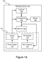
- FIG. 1A shows an illustrative system 100 for passive radio enabled power gating for a body mountable device according to one embodiment.
- the system 100 comprises wearable device 101, which comprises a wearable analyte sensor, e.g., a wearable glucose sensor, hydration sensor, oxygen sensor, or other type of sensor, e.g., a temperature sensor, motion sensor, blood pressure sensor, heart rate sensor, metabolic sensor, or any other type of sensor known in the art.
- wearable device 101 comprises a wearable patch comprising each of the components shown in Figure 1A .
- the wearable device 101 comprises a plurality of components that may comprise an active mode, e.g., a mode in which the device must receive power to operate.
- active components comprise, e.g., processor(s) 102, memory 104, antenna 106, and sensor 108.
- these components are not all active components, e.g., in some embodiments, sensor 108 and memory 104 may comprise both active and passive modes.
- one or more of these components may comprise a passive component, e.g., sensor 108 may comprise a component that does not have an active mode.
- processor 102 comprises one or more of a microprocessor, a digital signal processor (DSP), an application-specific integrated circuit (ASIC), field programmable gate arrays (FPGAs), and state machines.
- processors may further comprise programmable electronic devices such as PLCs, programmable interrupt controllers (PICs), programmable logic devices (PLDs), programmable read-only memories (PROMs), electronically programmable read-only memories (EPROMs or EEPROMs), or other similar devices.
- PLCs programmable interrupt controllers
- PLDs programmable logic devices
- PROMs programmable read-only memories
- EPROMs or EEPROMs electronically programmable read-only memories
- Processor 102 is in communication with memory 104.
- Memory 104 can comprise any suitable tangible (and non-transitory) computer-readable medium such as RAM, ROM, EEPROM, or the like, and may embody program components that configure operation of the computing device.
- Memory 104 may further comprise storage for processor 102 to store data, e.g., data received from a network interface or sensor 108.
- Memory 104 may comprise a static memory that can store data while in an unpowered state.
- Antenna 106 represents one or more of any components that facilitate a network connection. Examples include, but are not limited to, wired interfaces such as Ethernet, USB, IEEE 1394, and/or wireless interfaces such as IEEE 802.11, Bluetooth, or radio interfaces for accessing cellular telephone networks (e.g., transceiver/antenna for accessing a CDMA, GSM, UMTS, or other mobile communications network(s)). Thus, antenna 106 enables processor 102 to transmit or receive data from a remote device.
- wired interfaces such as Ethernet, USB, IEEE 1394, and/or wireless interfaces such as IEEE 802.11, Bluetooth, or radio interfaces for accessing cellular telephone networks (e.g., transceiver/antenna for accessing a CDMA, GSM, UMTS, or other mobile communications network(s)).
- antenna 106 enables processor 102 to transmit or receive data from a remote device.
- Sensor 108 comprises a sensor configured to measure information about a user, e.g., an analyte sensor, e.g., a wearable glucose sensor, hydration sensor, oxygen sensor, or other type of sensor, e.g., a temperature sensor, motion sensor, blood pressure sensor, heart rate sensor, metabolic sensor, or any other type of sensor known in the art.
- sensor 108 may comprise an active sensor, a passive sensor, or a sensor with both active and passive modes.
- wearable device 101 further comprises a passive radio gated power supply 150.
- the passive radio gated power supply 150 comprises a power supply 110, a switch 112, a Near Field Communication (NFC) antenna 114, and an RF Rectifier 116.
- NFC Near Field Communication
- Power supply 110 comprises a source of power, e.g., an onboard power source such as a battery, e.g., a rechargeable or non-rechargeable battery, for example, an alkaline battery, aluminum-air battery, aluminum-ion battery, dry cell, lithium battery, magnesium battery, mercury battery, nickel oxyhydroxide battery, lead-acid battery, lithium air battery, lithium ion battery, magnesium ion battery, nickel cadmium battery, sodium ion battery, or any other type of battery known in the art.
- power supply 110 may comprise an external power supply, e.g., a remote DC power supply coupled to wearable device 101 to power one or more components during or after manufacture, e.g., for testing, diagnostics, or charging.
- Switch 112 comprises a switch configured to interrupt the flow of current from power supply 112 to one or more of the active components of wearable device 101.
- switch 112 may comprise a transistor (e.g., a BJT or MOSFET), a relay, an electronically controlled switch, an op-amp circuit, or other switching circuit, e.g., a solid-state or non-solid state circuit configured to interrupt the flow of current from a power source to a load.
- switch 112 after switch 112 is closed it may be configured to automatically reopen after a predetermined period of time, e.g., one week or two weeks.
- switch 112 may be controlled by processor(s) 102 to be opened after the predetermined period of time, thus cutting the flow of current from power supply 110 to the active components.
- the user may reopen the switch 112 using an NFC enabled device as described in further detail below.
- NFC antenna 114 comprises an interface configured to transmit and receive NFC signals.
- NFC antenna 114 may comprise an NFC controller IC configured to receive/generate NFC signals, which are transmitted with an appropriately sized antenna.
- NFC antenna 114 and antenna 106 may be integrated into a single component.
- RF rectifier 116 is a component configured to receive NFC signals from NFC antenna 112 and convert those signals to current.
- RF rectifier 116 may comprise an RF to DC converter that takes energy received from Radio Frequency (RF) signals and converts that energy to DC current.
- the RF rectifier 116 is coupled to the switch 112, such that the current from the RF rectifier 116 is used to either open or close switch 112.
- the RF rectifier 116 directly controls switch 112. In other embodiments, rather than directly controlling switch 112, the RF rectifier 116 will indirectly control switch 112.
- RF rectifier 116 controls circuitry and or logic that demodulates communication signals received from antenna 106 or NFC antenna 114, or another wired or wireless communication interface, e.g., a serial peripheral interface (SPI). Based on these signals the circuitry may then control the switch 112 to provide power from power supply 110 to the active components in the wearable device 101.
- RF rectifier 116 may provide power to circuitry (e.g., analog or digital circuitry) configured to interpret NFC signals received by NCF antenna 114. This circuitry may then control switch 112 based on the content of the NFC signals.
- an NFC signal may comprise an indication to activate. Based on this signal the circuitry may provide power to all active components in wearable device 101.
- the NFC signal may comprise an indication to transmit.
- the circuitry may provide power to components needed to transmit data stored in memory 104 using one or more of antenna 106 or NFC antenna 114.
- wearable device 101 may comprise a single use patch for sensing the user's blood sugar level.
- the single use patch may be manufactured and shipped with switch 112 open, such that none of the active components consume energy from power source 110 until the switch 112 is closed.
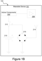
- Figure 1B shows another illustrative system for passive radio enabled power gating for a body mountable device according to one embodiment of the present disclosure.
- Figure 1B shows system 100, which comprises wearable device 151.
- Wearable device 151 comprises a wearable device of the same type described above with regard to Figure 1A .
- wearable device 151 comprises sensor 208, power supply 210, switch, 212, NFC antenna 214, RF rectifier 216, and active components 250.
- the wearable device 151 may activate the wearable device 151 using an NFC enabled device, e.g., an NFC enabled smartphone.
- the user may place the NFC enabled smartphone close to the wearable device 151 and activate NFC transmission.
- This NFC transmission is received by the NFC antenna 214.
- the NFC signals are used by RF rectifier 216 to generate a current. This current is provided to switch 212 and closes the switch, thus providing current from power supply 212 to active components 250, e.g., one or more processor(s) and a memory.
- the RF rectifier 216 directly controls switch 212.
- the RF rectifier 216 will indirectly control switch 212.
- the RF rectifier 216 may provide power to analog or digital logic that interprets (e.g., demodulates) NFC signals and controls the switch 212 based on the content of those signals.
- the processor may receive signals from sensor 208 and record those signals in the memory.
- the processor may be configured to reopen switch 212 after a predetermined period of time.
- This predetermined period of time may comprise the operating life of the wearable device 151 (e.g., a predetermined number of days or weeks, e.g., fourteen days).
- the active components 250 will stop consuming power from the power supply 210.
- the power supply 210 may comprise a battery that is specifically designed to provide power to the active components for only a relatively short period of time, e.g., the predetermined period. This may enable a relatively smaller, lighter, and cheaper battery to be used than would be required without passive radio enabled power gating.
- the user or a medical professional may download the sensor data stored in the memory. To do so, the user or the medical professional may reactivate the wearable device 151 using an NFC enabled device, e.g., an NFC enabled mobile device, such as a smartphone. These NFC signals may be used to close the switch 212, which then provides current to the active components.
- an NFC enabled device e.g., an NFC enabled mobile device, such as a smartphone.
- the processor may enter a transmit mode, in which the processor transmits the data stored in the memory using NFC antenna 214.
- the processor may automatically enter a transmit mode.
- the processor may then transmit the data stored in the memory to that remote device.
- Figure 2 shows an illustrative system 200 for passive radio enabled power gating for a body mountable device according to one embodiment.
- the system 200 comprises a single use patch 202 for sensing and recording data about the user (e.g., pulse, temperature, or blood sugar level).
- the single use patch may be manufactured and shipped with a switch interrupting the flow of current from its power supply to any active component, thus ensuring that battery power is not used during transportation or storage.
- NFC enabled device 204 may comprise a mobile device such as an NFC enabled smartphone or tablet, or some other computing device comprising NFC functionality. As discussed above, these NFC signals may be used to provide power to a switch to close the switch and allow current to flow from a power source to the active components of the wearable device 202.
- the processor may control the switch such that it is reopened after a predetermined period of time, e.g., the operating life of the wearable device 202. At this point the active components will stop consuming power from power supply.
- the power supply may comprise a battery that is specifically designed to provide power to the active components for only a relatively short period of time, e.g., the predetermined period.
- the user or a medical professional may download the sensor data stored in a memory.
- the user or the medical professional may reactivate the wearable device using an NFC enabled device to close the switch and thus allow current to flow from the battery to the active components.
- the wearable device 202 may enter a transmit mode, in which the processor transmits the data stored in a memory. This data may be transmitted using a second transmission means, e.g., a network interface such as a Wi-Fi or Bluetooth interface. Alternatively, the wearable device may be configured to transmit the measured sensor data using the same NFC interface used to close the switch. Once the sensor data is transmitted it may be reviewed locally, e.g., on the NFC enabled device, or transmitted to a further remote device, e.g., uploaded to a remote server using an Internet connection.
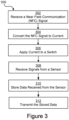
- Figure 3 is a flow chart for a method of passive radio enabled power gating for a body mountable device.
- the steps in Figure 3 may be implemented in program code executed by a processor. In some embodiments, these steps may be implemented by a group of processors. In some embodiments the steps shown in Figure 3 may be performed in a different order. Alternatively, in some embodiments, one or more of the steps shown in Figure 3 may be skipped, or additional steps not shown in Figure 3 may be performed. The steps below are described with reference to components described above with regard to system 100 shown in Figure 1A .
- the method 300 begins at step 302 when wearable device 101 receives a Near Field Communication (NFC) signal using NFC antenna 114.
- NFC Near Field Communication
- the NFC signal may be received from a mobile device, e.g., a smartphone or tablet comprising NFC capability.
- the NFC signal may be received from a purpose built device configured to activate wearable device 101.
- RF rectifier 116 converts the NFC signal to current.
- RF rectifier may comprise an RF to DC converter configured to convert NFC signals received from antenna 114 to DC current.
- the RF rectifier 116 applies current to switch 112.
- the RF rectifier 116 directly controls switch 112.
- switch 112 is electrically coupled to RF rectifier 116 in a configuration such that current from RF rectifier 116 is configured to close switch 112 and thus provide current to one or more active components on wearable device 101, e.g., processor 102, memory 104, and sensor 108.
- RF rectifier 116 may indirectly control switch 112, for example, by controlling analog or digital circuitry to apply current to switch 112.
- the analog or digital circuitry may be configured to demodulate NFC signals received from NFC antenna 114 and determine data contained in those signals.
- the circuitry may control switch 112 based on those signals, e.g., control the switch 112 to power all active components or control the switch 112 to power only components necessary to transmit data stored in memory 104 to a remote device. Further, switch 112 is configured to be reopened, for example, automatically after a predetermined period of time, after receipt of a control signal from processor 102, or after receipt of additional current from RF rectifier 116 (for example, the user may use a NFC enabled device to open switch 112 to deactivate wearable device 101).
- sensor 108 is configured to measure information about a user, e.g., sensor 108 may comprise an analyte sensor, e.g., a wearable glucose sensor, hydration sensor, oxygen sensor, or other type of sensor, e.g., a temperature sensor, motion sensor, blood pressure sensor, heart rate sensor, metabolic sensor, or any other type of sensor known in the art.
- sensor 108 may comprise an active sensor, a passive sensor, or a sensor with both active and passive modes.
- Memory 104 may comprise a static memory, e.g., flash or EEPROM, configured to store the sensor data received from processor 102 after switch 112 is reopened and power is no longer provided to the active components in wearable device 101.
- static memory e.g., flash or EEPROM
- the processor transmits the stored data to a remote device.
- the processor 102 may enter a transmit mode, in which the processor 102 transmits the data stored in memory 104 using antenna 106.
- processor 102 may transmit data stored in memory 104 using an NFC protocol and NFC antenna 114.
- passive radio enabled power gating for a body mountable device.
- a device implementing passive radio enabled power gating may use substantially less energy over the course of its lifetime because no energy is consumed during shipping or storage. This may allow smaller batteries to be used in such devices. These smaller batteries may be smaller, lighter, and cheaper, making a corresponding device using the battery, e.g., a single use wearable sensor, smaller, lighter, and cheaper.
- embodiments of the present disclosure may enable a single use device to upload stored data using only a relatively small amount of energy. This makes such devices more effective and reliable, because there is less risk that the user will be unable to retrieve measured data at the end of the device's usable life.
- configurations may be described as a process that is depicted as a flow diagram or block diagram. Although each may describe the operations as a sequential process, many of the operations can be performed in parallel or concurrently. In addition, the order of the operations may be rearranged. A process may have additional steps not included in the figure.
- examples of the methods may be implemented by hardware, software, firmware, middleware, microcode, hardware description languages, or any combination thereof. When implemented in software, firmware, middleware, or microcode, the program code or code segments to perform the necessary tasks may be stored in a non-transitory computer-readable medium such as a storage medium. Processors may perform the described tasks.
- a computer may comprise a processor or processors.
- the processor comprises or has access to a computer-readable medium, such as a random access memory (RAM) coupled to the processor.
- RAM random access memory
- the processor executes computer-executable program instructions stored in memory, such as executing one or more computer programs including a sensor sampling routine, selection routines, and other routines to perform the methods described above.
- Such processors may comprise a microprocessor, a digital signal processor (DSP), an application-specific integrated circuit (ASIC), field programmable gate arrays (FPGAs), and state machines.
- Such processors may further comprise programmable electronic devices such as PLCs, programmable interrupt controllers (PICs), programmable logic devices (PLDs), programmable read-only memories (PROMs), electronically programmable read-only memories (EPROMs or EEPROMs), or other similar devices.
- Such processors may comprise, or may be in communication with, media, for example tangible computer-readable media, that may store instructions that, when executed by the processor, can cause the processor to perform the steps described herein as carried out, or assisted, by a processor.
- Embodiments of computer-readable media may comprise, but are not limited to, all electronic, optical, magnetic, or other storage devices capable of providing a processor, such as the processor in a web server, with computer-readable instructions.
- Other examples of media comprise, but are not limited to, a floppy disk, CD-ROM, magnetic disk, memory chip, ROM, RAM, ASIC, configured processor, all optical media, all magnetic tape or other magnetic media, or any other medium from which a computer processor can read.
- various other devices may include computer-readable media, such as a router, private or public network, or other transmission device.
- the processor, and the processing, described may be in one or more structures, and may be dispersed through one or more structures.
- the processor may comprise code for carrying out one or more of the methods (or parts of methods) described herein.
- a or B or C includes any or all of the following alternative combinations as appropriate for a particular usage: A alone; B alone; C alone; A and B only; A and C only; B and C only; and A and B and C.
Landscapes
- Engineering & Computer Science (AREA)
- Health & Medical Sciences (AREA)
- Life Sciences & Earth Sciences (AREA)
- Computer Networks & Wireless Communication (AREA)
- Physics & Mathematics (AREA)
- Signal Processing (AREA)
- Pathology (AREA)
- Surgery (AREA)
- Veterinary Medicine (AREA)
- Biophysics (AREA)
- Public Health (AREA)
- Biomedical Technology (AREA)
- Heart & Thoracic Surgery (AREA)
- Medical Informatics (AREA)
- Molecular Biology (AREA)
- General Health & Medical Sciences (AREA)
- Animal Behavior & Ethology (AREA)
- General Physics & Mathematics (AREA)
- Optics & Photonics (AREA)
- Emergency Medicine (AREA)
- Measurement Of The Respiration, Hearing Ability, Form, And Blood Characteristics Of Living Organisms (AREA)
- Measuring And Recording Apparatus For Diagnosis (AREA)
- Near-Field Transmission Systems (AREA)
Claims (15)
- Verfahren zum Leistungsaustasten, das Folgendes umfasst:Empfangen (302) eines Nahfeldkommunikations-, NFC-, Signals unter Verwendung einer NFC-Antenne (114);dadurch gekennzeichnet, dass das Verfahren ferner Folgendes umfasst:Umwandeln (304) des NFC-Signals in einen Strom;Anlegen (306) des Stroms an einen Schalter (112), der angeordnet ist, um den Stromfluss zwischen einer Leistungsversorgung (110) und einer Last zu unterbrechen, wobei der Schalter durch den Strom geöffnet oder geschlossen wird, wobei die Last einen Prozessor (102) und einen Glucosesensor (108) umfasst;wenn der Schalter geschlossen ist, Empfangen (308) von Signalen, umfassend Sensordaten, von dem Glucosesensor und Speichern (310) der Sensordaten in einem Speicher.
- Verfahren nach Anspruch 1, das ferner Folgendes umfasst:Aktivieren einer Netzwerkschnittstelle teilweise basierend auf einem zweiten NFC-Signal; undÜbertragen (312) der gespeicherten Sensordaten an eine entfernte Vorrichtung unter Verwendung der Netzwerkschnittstelle.
- Verfahren nach Anspruch 1, wobei der elektronische Schalter eines oder mehrere aus Folgenden umfasst: einen Transistor, ein Relais oder einen elektronisch gesteuerten Schalter.
- Verfahren nach Anspruch 1, wobei die Leistungsversorgung eine Batterie umfasst.
- Verfahren nach Anspruch 1, das ferner das Übertragen von Daten, die den Sensordaten zugeordnet sind, an eine entfernte Vorrichtung umfasst.
- Verfahren nach Anspruch 5, wobei die Daten unter Verwendung der NFC-Antenne übertragen werden.
- Verfahren nach Anspruch 5, wobei die Daten unter Verwendung einer zweiten Antenne übertragen werden, und wobei die zweite Antenne ausgelegt ist, um Daten unter Verwendung eines anderen Protokolls zu übertragen als die NFC-Antenne.
- Verfahren nach Anspruch 1, das ferner das Übertragen der gespeicherten Daten unter Verwendung der NFC-Antenne umfasst.
- System (100) zum Leistungsaustasten für einen tragbaren Sensor, wobei das System Folgendes umfasst:eine Leistungsversorgung (110);eine Nahfeldkommunikations-, NFC-, Antenne (114) zum Empfangen von NFC-Signalen;dadurch gekennzeichnet, dass das System ferner Folgendes umfasst:einen Hochfrequenz-, HF-, Gleichrichter (116) der elektrisch mit der NFC-Antenne gekoppelt ist, um einen Strom basierend auf einem ersten Signal zu erzeugen, das von der NFC-Antenne (114) empfangen wurde;einen elektronischen Schalter (112), der zwischen der Leistungsversorgung und einem Glucosesensor (108) gekoppelt ist, um eine elektrische Verbindung zwischen der Leistungsversorgung und dem Glucosesensor (108) zu steuern, wobei der HF-Gleichrichter (116) ferner mit dem elektronischen Schalter (116) gekoppelt ist, um den elektronischen Schalter mit dem Strom zu beaufschlagen, um einen Zustand des elektronischen Schalters zu ändern;einen Prozessor (102), wobei der elektronische Schalter ferner zwischen der Leistungsversorgung und dem Prozessor gekoppelt ist, wobei der Prozessor mit dem Glucosesensor (108) gekoppelt ist, um Sensordaten von dem Glucosesensor (108) zu empfangen, wenn der Schalter geschlossen ist;einen Speicher (104), der mit dem Prozessor (102) gekoppelt und ausgelegt ist, um die Sensordaten zu speichern.
- System nach Anspruch 9, wobei, wenn der elektronische Schalter geschlossen ist, der Prozessor ferner ausgelegt ist zum:Aktivieren einer Netzwerkschnittstelle, die mit dem Prozessor gekoppelt ist; undÜbertragen der Sensordaten, die in dem Speicher (104) gespeichert sind, an eine entfernte Vorrichtung unter Verwendung der Netzwerkschnittstelle als Reaktion auf ein zweites NFC-Signal.
- System nach Anspruch 9, wobei der elektronische Schalter eines oder mehrere aus Folgenden umfasst: einen Transistor, ein Relais oder einen elektronisch gesteuerten Schalter.
- System nach Anspruch 9, wobei die Leistungsversorgung eine Batterie umfasst.
- System nach Anspruch 9, wobei, wenn der elektronische Schalter geschlossen ist, der Prozessor ferner ausgelegt ist um Daten, die den Sensordaten zugeordnet sind, an eine entfernte Vorrichtung zu übertragen.
- System nach Anspruch 13, wobei die Daten unter Verwendung der NFC-Antenne übertragen werden.
- System nach Anspruch 13, wobei die Daten unter Verwendung einer zweiten Antenne übertragen werden, und wobei die zweite Antenne ausgelegt ist, um Daten unter Verwendung eines anderen Protokolls zu übertragen als die NFC-Antenne.
Priority Applications (1)
| Application Number | Priority Date | Filing Date | Title |
|---|---|---|---|
| EP24193904.0A EP4486019A3 (de) | 2016-07-25 | 2017-06-27 | Systeme und verfahren für passives funkaktiviertes power-gating für eine körpermontierbare vorrichtung |
Applications Claiming Priority (3)
| Application Number | Priority Date | Filing Date | Title |
|---|---|---|---|
| US15/218,587 US9967001B2 (en) | 2016-07-25 | 2016-07-25 | Systems and methods for passive radio enabled power gating for a body mountable device |
| EP17735752.2A EP3488434B1 (de) | 2016-07-25 | 2017-06-27 | Systeme und verfahren zur passiven funkgesteuerten leistungsanpassung für eine körpermontierbare vorrichtung |
| PCT/US2017/039380 WO2018022235A1 (en) | 2016-07-25 | 2017-06-27 | Systems and methods for passive radio enabled power gating for a body mountable device |
Related Parent Applications (1)
| Application Number | Title | Priority Date | Filing Date |
|---|---|---|---|
| EP17735752.2A Division EP3488434B1 (de) | 2016-07-25 | 2017-06-27 | Systeme und verfahren zur passiven funkgesteuerten leistungsanpassung für eine körpermontierbare vorrichtung |
Related Child Applications (2)
| Application Number | Title | Priority Date | Filing Date |
|---|---|---|---|
| EP24193904.0A Division EP4486019A3 (de) | 2016-07-25 | 2017-06-27 | Systeme und verfahren für passives funkaktiviertes power-gating für eine körpermontierbare vorrichtung |
| EP24193904.0A Division-Into EP4486019A3 (de) | 2016-07-25 | 2017-06-27 | Systeme und verfahren für passives funkaktiviertes power-gating für eine körpermontierbare vorrichtung |
Publications (3)
| Publication Number | Publication Date |
|---|---|
| EP4184470A1 EP4184470A1 (de) | 2023-05-24 |
| EP4184470B1 true EP4184470B1 (de) | 2024-08-14 |
| EP4184470B8 EP4184470B8 (de) | 2024-09-25 |
Family
ID=59285392
Family Applications (3)
| Application Number | Title | Priority Date | Filing Date |
|---|---|---|---|
| EP24193904.0A Pending EP4486019A3 (de) | 2016-07-25 | 2017-06-27 | Systeme und verfahren für passives funkaktiviertes power-gating für eine körpermontierbare vorrichtung |
| EP17735752.2A Active EP3488434B1 (de) | 2016-07-25 | 2017-06-27 | Systeme und verfahren zur passiven funkgesteuerten leistungsanpassung für eine körpermontierbare vorrichtung |
| EP22202313.7A Active EP4184470B8 (de) | 2016-07-25 | 2017-06-27 | Systeme und verfahren zur passiven funkgesteuerten leistungsanpassung für eine körpermontierbare vorrichtung |
Family Applications Before (2)
| Application Number | Title | Priority Date | Filing Date |
|---|---|---|---|
| EP24193904.0A Pending EP4486019A3 (de) | 2016-07-25 | 2017-06-27 | Systeme und verfahren für passives funkaktiviertes power-gating für eine körpermontierbare vorrichtung |
| EP17735752.2A Active EP3488434B1 (de) | 2016-07-25 | 2017-06-27 | Systeme und verfahren zur passiven funkgesteuerten leistungsanpassung für eine körpermontierbare vorrichtung |
Country Status (5)
| Country | Link |
|---|---|
| US (2) | US9967001B2 (de) |
| EP (3) | EP4486019A3 (de) |
| CN (1) | CN109496330B (de) |
| TW (1) | TWI745406B (de) |
| WO (1) | WO2018022235A1 (de) |
Families Citing this family (13)
| Publication number | Priority date | Publication date | Assignee | Title |
|---|---|---|---|---|
| US11457809B1 (en) * | 2015-12-08 | 2022-10-04 | Verily Life Sciences Llc | NFC beacons for bidirectional communication between an electrochemical sensor and a reader device |
| US11109121B2 (en) * | 2018-05-10 | 2021-08-31 | Physio-Control, Inc. | Systems and methods of secure communication of data from medical devices |
| US10763920B2 (en) * | 2018-05-23 | 2020-09-01 | Infineon Technologies Ag | Multipolymer sensor array utilizing NFC |
| US11426101B2 (en) | 2018-07-09 | 2022-08-30 | Verily Life Sciences Llc | Systems and methods for sensors with multimode wireless communications and for enabling NFC communications with a wearable biosensor |
| US11038555B2 (en) | 2018-08-06 | 2021-06-15 | Verily Life Sciences Llc | Systems and methods for enabling NFC communications with a wearable biosensor |
| KR102200139B1 (ko) * | 2018-08-07 | 2021-01-08 | 주식회사 아이센스 | 연속혈당측정기의 동작 제어 장치 |
| WO2020206372A1 (en) * | 2019-04-03 | 2020-10-08 | Pb Inc. | Temperature sensor patch wirelessly connected to a smart device |
| EP4032163A1 (de) | 2019-09-18 | 2022-07-27 | Ascensia Diabetes Care Holdings AG | Automatische aktivierung eines senders zur kontinuierlichen glukoseüberwachung (cgm) |
| US11152664B2 (en) | 2019-12-24 | 2021-10-19 | Anexa Labs Llc | Compact electronics with optical sensors |
| US11327443B1 (en) * | 2020-10-23 | 2022-05-10 | Anexa Labs Llc | Wearable device for monitoring health metrics |
| CA3105572C (en) * | 2021-01-13 | 2022-01-18 | Ryan Smith | Tracking device and system |
| US12088201B2 (en) * | 2022-01-27 | 2024-09-10 | Dexcom, Inc. | System and method for activating an analyte monitoring system |
| EP4687664A1 (de) * | 2023-04-07 | 2026-02-11 | Dexcom, Inc. | Nahfeldkommunikationsbasierte leistungssteuerung für ein analytsensorsystem |
Family Cites Families (16)
| Publication number | Priority date | Publication date | Assignee | Title |
|---|---|---|---|---|
| DE102005019306B4 (de) * | 2005-04-26 | 2011-09-01 | Disetronic Licensing Ag | Energieoptimierte Datenübertragung eines medizinischen Geräts |
| US20080116847A1 (en) | 2006-09-01 | 2008-05-22 | Bio Aim Technologies Holding Ltd. | Systems and methods for wireless power transfer |
| EP2254461A4 (de) | 2008-03-19 | 2012-12-26 | Ericsson Telefon Ab L M | Nfc-kommunikationen für implantierte geräte zur erfassung von medizinischen daten |
| US8947041B2 (en) * | 2008-09-02 | 2015-02-03 | Qualcomm Incorporated | Bidirectional wireless power transmission |
| US9656092B2 (en) | 2009-05-12 | 2017-05-23 | Chronicmobile, Inc. | Methods and systems for managing, controlling and monitoring medical devices via one or more software applications functioning in a secure environment |
| EP2473963A4 (de) * | 2009-08-31 | 2014-01-08 | Abbott Diabetes Care Inc | Medizinische geräte und verfahren |
| TWI451238B (zh) | 2010-07-28 | 2014-09-01 | Mstar Semiconductor Inc | 電源控制裝置及其方法、以及使用其之行動裝置 |
| AT512101A2 (de) | 2011-10-31 | 2013-05-15 | Seibersdorf Labor Gmbh | Messeinrichtung zur glukosemessung |
| US20130116526A1 (en) * | 2011-11-09 | 2013-05-09 | Telcare, Inc. | Handheld Blood Glucose Monitoring Device with Messaging Capability |
| CN204576485U (zh) * | 2011-12-15 | 2015-08-19 | 贝克顿·迪金森公司 | 生理条件监视系统、生理条件传感器和生理条件仪表 |
| US9110897B2 (en) * | 2012-11-16 | 2015-08-18 | Electronics And Telecommunications Research Institute | Sensor tag and method of providing service using the same |
| WO2014179343A1 (en) | 2013-04-30 | 2014-11-06 | Abbott Diabetes Care Inc. | Systems, devices, and methods for energy efficient electrical device activation |
| US20150075770A1 (en) * | 2013-05-31 | 2015-03-19 | Michael Linley Fripp | Wireless activation of wellbore tools |
| EP3151906B1 (de) * | 2014-06-03 | 2019-12-11 | Pop Test Abuse Deterrent Technology LLC | Zur drahtlosen kommunikation konfigurierte arzneimittelvorrichtung |
| KR102240512B1 (ko) * | 2014-07-31 | 2021-04-16 | 삼성전자주식회사 | 혈당 측정 장치, 혈당 측정 방법 및 혈당 측정 모듈을 포함하는 전자 장치 |
| EP3221977A4 (de) * | 2014-11-18 | 2019-01-23 | Mc10, Inc. | System, vorrichtung und verfahren zur aktivierung einer elektronischen vorrichtung |
-
2016
- 2016-07-25 US US15/218,587 patent/US9967001B2/en active Active
-
2017
- 2017-06-27 CN CN201780046360.7A patent/CN109496330B/zh active Active
- 2017-06-27 EP EP24193904.0A patent/EP4486019A3/de active Pending
- 2017-06-27 WO PCT/US2017/039380 patent/WO2018022235A1/en not_active Ceased
- 2017-06-27 EP EP17735752.2A patent/EP3488434B1/de active Active
- 2017-06-27 EP EP22202313.7A patent/EP4184470B8/de active Active
- 2017-07-21 TW TW106124488A patent/TWI745406B/zh active
-
2018
- 2018-04-04 US US15/945,286 patent/US20180234133A1/en not_active Abandoned
Also Published As
| Publication number | Publication date |
|---|---|
| US20180234133A1 (en) | 2018-08-16 |
| TW201816741A (zh) | 2018-05-01 |
| EP3488434A1 (de) | 2019-05-29 |
| WO2018022235A1 (en) | 2018-02-01 |
| US20180026678A1 (en) | 2018-01-25 |
| US9967001B2 (en) | 2018-05-08 |
| EP4184470A1 (de) | 2023-05-24 |
| EP4486019A3 (de) | 2025-02-26 |
| EP4486019A2 (de) | 2025-01-01 |
| TWI745406B (zh) | 2021-11-11 |
| EP4184470B8 (de) | 2024-09-25 |
| CN109496330B (zh) | 2020-09-22 |
| EP3488434B1 (de) | 2022-10-19 |
| CN109496330A (zh) | 2019-03-19 |
Similar Documents
| Publication | Publication Date | Title |
|---|---|---|
| EP4184470B1 (de) | Systeme und verfahren zur passiven funkgesteuerten leistungsanpassung für eine körpermontierbare vorrichtung | |
| US8129949B2 (en) | Device and method for instantaneous load reduction configuration to prevent under voltage condition | |
| US20120316414A1 (en) | Systems, methods and apparatus for powering devices using rf energy from a mobile transmitter | |
| US10572270B1 (en) | Wakeup from hibernation state using motion sensor | |
| TWI699125B (zh) | 用於能量擷取裝置之中斷通知及脈絡保存技術 | |
| JP5914599B2 (ja) | 供給電圧管理用電子回路を備えるスマート電池 | |
| JP2019531042A (ja) | 無線バッテリー管理システム及びこれを含むバッテリーパック | |
| US9191480B2 (en) | Method for performing alarm function and electronic device thereof | |
| US20180192374A1 (en) | Low power location tracking device | |
| US20140106676A1 (en) | Case with embedded electronics to provide interface between glucose sensor and smartphone | |
| JP2017509454A (ja) | 口腔ケアシステム | |
| US20160141730A1 (en) | Method of Controlling Different Kinds of Battery Cells and Electronic Device for Same | |
| US9961636B2 (en) | Electronic device system, terminal device, electronic device system control method, and control program | |
| TWI853826B (zh) | 具有近場交互裝置之測量設備、操作該測量設備之方法,程式元件,及電腦可讀媒介 | |
| KR20180113861A (ko) | 트래픽 제어 방법 및 그 전자 장치 | |
| EP2975490B1 (de) | Verfahren und vorrichtung für leistungsverwaltung | |
| KR102780292B1 (ko) | 배터리 관리 시스템, 배터리 관리 방법, 배터리 팩 및 전기 차량 | |
| CN105744604A (zh) | 基于android系统的WIFI模块功耗控制装置及方法 | |
| KR20150105318A (ko) | 양의 측정을 위한 측정 시스템 및 측정을 위한 방법 | |
| WO2015189462A1 (en) | Usb energy harvesting | |
| CN110832730A (zh) | 用于管理充电的方法和电子装置 | |
| US9526072B1 (en) | Method, device, and system for operating a multi-function voice-collaboration device to manage battery life | |
| US20220352927A1 (en) | NFC-Enabled Constrained Device, NFC-Enabled Control Device, and Method Thereof | |
| JP7521717B2 (ja) | センシング装置及び方法 | |
| WO2016205099A1 (en) | Battery life extension for a communication device |
Legal Events
| Date | Code | Title | Description |
|---|---|---|---|
| PUAI | Public reference made under article 153(3) epc to a published international application that has entered the european phase |
Free format text: ORIGINAL CODE: 0009012 |
|
| STAA | Information on the status of an ep patent application or granted ep patent |
Free format text: STATUS: THE APPLICATION HAS BEEN PUBLISHED |
|
| AC | Divisional application: reference to earlier application |
Ref document number: 3488434 Country of ref document: EP Kind code of ref document: P |
|
| AK | Designated contracting states |
Kind code of ref document: A1 Designated state(s): AL AT BE BG CH CY CZ DE DK EE ES FI FR GB GR HR HU IE IS IT LI LT LU LV MC MK MT NL NO PL PT RO RS SE SI SK SM TR |
|
| RAP1 | Party data changed (applicant data changed or rights of an application transferred) |
Owner name: DEXCOM, INC. Owner name: VERILY LIFE SCIENCES LLC |
|
| STAA | Information on the status of an ep patent application or granted ep patent |
Free format text: STATUS: REQUEST FOR EXAMINATION WAS MADE |
|
| 17P | Request for examination filed |
Effective date: 20231017 |
|
| RBV | Designated contracting states (corrected) |
Designated state(s): AL AT BE BG CH CY CZ DE DK EE ES FI FR GB GR HR HU IE IS IT LI LT LU LV MC MK MT NL NO PL PT RO RS SE SI SK SM TR |
|
| GRAP | Despatch of communication of intention to grant a patent |
Free format text: ORIGINAL CODE: EPIDOSNIGR1 |
|
| STAA | Information on the status of an ep patent application or granted ep patent |
Free format text: STATUS: GRANT OF PATENT IS INTENDED |
|
| INTG | Intention to grant announced |
Effective date: 20240307 |
|
| GRAS | Grant fee paid |
Free format text: ORIGINAL CODE: EPIDOSNIGR3 |
|
| GRAA | (expected) grant |
Free format text: ORIGINAL CODE: 0009210 |
|
| STAA | Information on the status of an ep patent application or granted ep patent |
Free format text: STATUS: THE PATENT HAS BEEN GRANTED |
|
| AC | Divisional application: reference to earlier application |
Ref document number: 3488434 Country of ref document: EP Kind code of ref document: P |
|
| AK | Designated contracting states |
Kind code of ref document: B1 Designated state(s): AL AT BE BG CH CY CZ DE DK EE ES FI FR GB GR HR HU IE IS IT LI LT LU LV MC MK MT NL NO PL PT RO RS SE SI SK SM TR |
|
| REG | Reference to a national code |
Ref country code: GB Ref legal event code: FG4D |
|
| REG | Reference to a national code |
Ref country code: CH Ref legal event code: EP |
|
| REG | Reference to a national code |
Ref country code: DE Ref legal event code: R081 Ref document number: 602017084205 Country of ref document: DE Owner name: VERILY LIFE SCIENCES LLC, DALLAS, US Free format text: FORMER OWNERS: DEXCOM, INC., SAN DIEGO, CA, US; VERILY LIFE SCIENCES LLC, SOUTH SAN FRANCISCO, CA, US Ref country code: DE Ref legal event code: R081 Ref document number: 602017084205 Country of ref document: DE Owner name: DEXCOM, INC., SAN DIEGO, US Free format text: FORMER OWNERS: DEXCOM, INC., SAN DIEGO, CA, US; VERILY LIFE SCIENCES LLC, SOUTH SAN FRANCISCO, CA, US |
|
| REG | Reference to a national code |
Ref country code: CH Ref legal event code: PK Free format text: BERICHTIGUNG B8 |
|
| REG | Reference to a national code |
Ref country code: DE Ref legal event code: R082 Ref document number: 602017084205 Country of ref document: DE |
|
| REG | Reference to a national code |
Ref country code: DE Ref legal event code: R096 Ref document number: 602017084205 Country of ref document: DE |
|
| RAP4 | Party data changed (patent owner data changed or rights of a patent transferred) |
Owner name: DEXCOM, INC. Owner name: VERILY LIFE SCIENCES LLC |
|
| REG | Reference to a national code |
Ref country code: IE Ref legal event code: FG4D Ref country code: NL Ref legal event code: FP |
|
| REG | Reference to a national code |
Ref country code: SE Ref legal event code: TRGR |
|
| P01 | Opt-out of the competence of the unified patent court (upc) registered |
Free format text: CASE NUMBER: APP_51586/2024 Effective date: 20240912 |
|
| REG | Reference to a national code |
Ref country code: LT Ref legal event code: MG9D |
|
| REG | Reference to a national code |
Ref country code: AT Ref legal event code: MK05 Ref document number: 1714050 Country of ref document: AT Kind code of ref document: T Effective date: 20240814 |
|
| PG25 | Lapsed in a contracting state [announced via postgrant information from national office to epo] |
Ref country code: GR Free format text: LAPSE BECAUSE OF FAILURE TO SUBMIT A TRANSLATION OF THE DESCRIPTION OR TO PAY THE FEE WITHIN THE PRESCRIBED TIME-LIMIT Effective date: 20241115 Ref country code: PL Free format text: LAPSE BECAUSE OF FAILURE TO SUBMIT A TRANSLATION OF THE DESCRIPTION OR TO PAY THE FEE WITHIN THE PRESCRIBED TIME-LIMIT Effective date: 20240814 Ref country code: FI Free format text: LAPSE BECAUSE OF FAILURE TO SUBMIT A TRANSLATION OF THE DESCRIPTION OR TO PAY THE FEE WITHIN THE PRESCRIBED TIME-LIMIT Effective date: 20240814 Ref country code: PT Free format text: LAPSE BECAUSE OF FAILURE TO SUBMIT A TRANSLATION OF THE DESCRIPTION OR TO PAY THE FEE WITHIN THE PRESCRIBED TIME-LIMIT Effective date: 20241216 |
|
| PG25 | Lapsed in a contracting state [announced via postgrant information from national office to epo] |
Ref country code: BG Free format text: LAPSE BECAUSE OF FAILURE TO SUBMIT A TRANSLATION OF THE DESCRIPTION OR TO PAY THE FEE WITHIN THE PRESCRIBED TIME-LIMIT Effective date: 20240814 |
|
| PG25 | Lapsed in a contracting state [announced via postgrant information from national office to epo] |
Ref country code: LV Free format text: LAPSE BECAUSE OF FAILURE TO SUBMIT A TRANSLATION OF THE DESCRIPTION OR TO PAY THE FEE WITHIN THE PRESCRIBED TIME-LIMIT Effective date: 20240814 |
|
| PG25 | Lapsed in a contracting state [announced via postgrant information from national office to epo] |
Ref country code: AT Free format text: LAPSE BECAUSE OF FAILURE TO SUBMIT A TRANSLATION OF THE DESCRIPTION OR TO PAY THE FEE WITHIN THE PRESCRIBED TIME-LIMIT Effective date: 20240814 Ref country code: IS Free format text: LAPSE BECAUSE OF FAILURE TO SUBMIT A TRANSLATION OF THE DESCRIPTION OR TO PAY THE FEE WITHIN THE PRESCRIBED TIME-LIMIT Effective date: 20241214 |
|
| PG25 | Lapsed in a contracting state [announced via postgrant information from national office to epo] |
Ref country code: HR Free format text: LAPSE BECAUSE OF FAILURE TO SUBMIT A TRANSLATION OF THE DESCRIPTION OR TO PAY THE FEE WITHIN THE PRESCRIBED TIME-LIMIT Effective date: 20240814 |
|
| PG25 | Lapsed in a contracting state [announced via postgrant information from national office to epo] |
Ref country code: RS Free format text: LAPSE BECAUSE OF FAILURE TO SUBMIT A TRANSLATION OF THE DESCRIPTION OR TO PAY THE FEE WITHIN THE PRESCRIBED TIME-LIMIT Effective date: 20241114 Ref country code: ES Free format text: LAPSE BECAUSE OF FAILURE TO SUBMIT A TRANSLATION OF THE DESCRIPTION OR TO PAY THE FEE WITHIN THE PRESCRIBED TIME-LIMIT Effective date: 20240814 |
|
| PG25 | Lapsed in a contracting state [announced via postgrant information from national office to epo] |
Ref country code: RS Free format text: LAPSE BECAUSE OF FAILURE TO SUBMIT A TRANSLATION OF THE DESCRIPTION OR TO PAY THE FEE WITHIN THE PRESCRIBED TIME-LIMIT Effective date: 20241114 Ref country code: PT Free format text: LAPSE BECAUSE OF FAILURE TO SUBMIT A TRANSLATION OF THE DESCRIPTION OR TO PAY THE FEE WITHIN THE PRESCRIBED TIME-LIMIT Effective date: 20241216 Ref country code: PL Free format text: LAPSE BECAUSE OF FAILURE TO SUBMIT A TRANSLATION OF THE DESCRIPTION OR TO PAY THE FEE WITHIN THE PRESCRIBED TIME-LIMIT Effective date: 20240814 Ref country code: LV Free format text: LAPSE BECAUSE OF FAILURE TO SUBMIT A TRANSLATION OF THE DESCRIPTION OR TO PAY THE FEE WITHIN THE PRESCRIBED TIME-LIMIT Effective date: 20240814 Ref country code: IS Free format text: LAPSE BECAUSE OF FAILURE TO SUBMIT A TRANSLATION OF THE DESCRIPTION OR TO PAY THE FEE WITHIN THE PRESCRIBED TIME-LIMIT Effective date: 20241214 Ref country code: HR Free format text: LAPSE BECAUSE OF FAILURE TO SUBMIT A TRANSLATION OF THE DESCRIPTION OR TO PAY THE FEE WITHIN THE PRESCRIBED TIME-LIMIT Effective date: 20240814 Ref country code: GR Free format text: LAPSE BECAUSE OF FAILURE TO SUBMIT A TRANSLATION OF THE DESCRIPTION OR TO PAY THE FEE WITHIN THE PRESCRIBED TIME-LIMIT Effective date: 20241115 Ref country code: FI Free format text: LAPSE BECAUSE OF FAILURE TO SUBMIT A TRANSLATION OF THE DESCRIPTION OR TO PAY THE FEE WITHIN THE PRESCRIBED TIME-LIMIT Effective date: 20240814 Ref country code: ES Free format text: LAPSE BECAUSE OF FAILURE TO SUBMIT A TRANSLATION OF THE DESCRIPTION OR TO PAY THE FEE WITHIN THE PRESCRIBED TIME-LIMIT Effective date: 20240814 Ref country code: BG Free format text: LAPSE BECAUSE OF FAILURE TO SUBMIT A TRANSLATION OF THE DESCRIPTION OR TO PAY THE FEE WITHIN THE PRESCRIBED TIME-LIMIT Effective date: 20240814 Ref country code: AT Free format text: LAPSE BECAUSE OF FAILURE TO SUBMIT A TRANSLATION OF THE DESCRIPTION OR TO PAY THE FEE WITHIN THE PRESCRIBED TIME-LIMIT Effective date: 20240814 |
|
| PG25 | Lapsed in a contracting state [announced via postgrant information from national office to epo] |
Ref country code: SM Free format text: LAPSE BECAUSE OF FAILURE TO SUBMIT A TRANSLATION OF THE DESCRIPTION OR TO PAY THE FEE WITHIN THE PRESCRIBED TIME-LIMIT Effective date: 20240814 Ref country code: DK Free format text: LAPSE BECAUSE OF FAILURE TO SUBMIT A TRANSLATION OF THE DESCRIPTION OR TO PAY THE FEE WITHIN THE PRESCRIBED TIME-LIMIT Effective date: 20240814 Ref country code: RO Free format text: LAPSE BECAUSE OF FAILURE TO SUBMIT A TRANSLATION OF THE DESCRIPTION OR TO PAY THE FEE WITHIN THE PRESCRIBED TIME-LIMIT Effective date: 20240814 |
|
| PG25 | Lapsed in a contracting state [announced via postgrant information from national office to epo] |
Ref country code: CZ Free format text: LAPSE BECAUSE OF FAILURE TO SUBMIT A TRANSLATION OF THE DESCRIPTION OR TO PAY THE FEE WITHIN THE PRESCRIBED TIME-LIMIT Effective date: 20240814 |
|
| PG25 | Lapsed in a contracting state [announced via postgrant information from national office to epo] |
Ref country code: IT Free format text: LAPSE BECAUSE OF FAILURE TO SUBMIT A TRANSLATION OF THE DESCRIPTION OR TO PAY THE FEE WITHIN THE PRESCRIBED TIME-LIMIT Effective date: 20240814 Ref country code: SK Free format text: LAPSE BECAUSE OF FAILURE TO SUBMIT A TRANSLATION OF THE DESCRIPTION OR TO PAY THE FEE WITHIN THE PRESCRIBED TIME-LIMIT Effective date: 20240814 |
|
| REG | Reference to a national code |
Ref country code: DE Ref legal event code: R097 Ref document number: 602017084205 Country of ref document: DE |
|
| PGFP | Annual fee paid to national office [announced via postgrant information from national office to epo] |
Ref country code: NL Payment date: 20250520 Year of fee payment: 9 |
|
| PLBE | No opposition filed within time limit |
Free format text: ORIGINAL CODE: 0009261 |
|
| STAA | Information on the status of an ep patent application or granted ep patent |
Free format text: STATUS: NO OPPOSITION FILED WITHIN TIME LIMIT |
|
| PGFP | Annual fee paid to national office [announced via postgrant information from national office to epo] |
Ref country code: DE Payment date: 20250520 Year of fee payment: 9 |
|
| PGFP | Annual fee paid to national office [announced via postgrant information from national office to epo] |
Ref country code: GB Payment date: 20250520 Year of fee payment: 9 |
|
| PGFP | Annual fee paid to national office [announced via postgrant information from national office to epo] |
Ref country code: NO Payment date: 20250522 Year of fee payment: 9 |
|
| PGFP | Annual fee paid to national office [announced via postgrant information from national office to epo] |
Ref country code: FR Payment date: 20250520 Year of fee payment: 9 |
|
| 26N | No opposition filed |
Effective date: 20250515 |
|
| PGFP | Annual fee paid to national office [announced via postgrant information from national office to epo] |
Ref country code: IE Payment date: 20250522 Year of fee payment: 9 |
|
| PGFP | Annual fee paid to national office [announced via postgrant information from national office to epo] |
Ref country code: SE Payment date: 20250520 Year of fee payment: 9 |
|
| REG | Reference to a national code |
Ref country code: CH Ref legal event code: H13 Free format text: ST27 STATUS EVENT CODE: U-0-0-H10-H13 (AS PROVIDED BY THE NATIONAL OFFICE) Effective date: 20260127 |
|
| PG25 | Lapsed in a contracting state [announced via postgrant information from national office to epo] |
Ref country code: MC Free format text: LAPSE BECAUSE OF FAILURE TO SUBMIT A TRANSLATION OF THE DESCRIPTION OR TO PAY THE FEE WITHIN THE PRESCRIBED TIME-LIMIT Effective date: 20240814 |