EP4184441A1 - System and method for recreating image with repeating patterns of graphical image file to reduce storage space - Google Patents
System and method for recreating image with repeating patterns of graphical image file to reduce storage space Download PDFInfo
- Publication number
- EP4184441A1 EP4184441A1 EP22207060.9A EP22207060A EP4184441A1 EP 4184441 A1 EP4184441 A1 EP 4184441A1 EP 22207060 A EP22207060 A EP 22207060A EP 4184441 A1 EP4184441 A1 EP 4184441A1
- Authority
- EP
- European Patent Office
- Prior art keywords
- repeating pattern
- sequence
- file
- graphical image
- image file
- Prior art date
- Legal status (The legal status is an assumption and is not a legal conclusion. Google has not performed a legal analysis and makes no representation as to the accuracy of the status listed.)
- Granted
Links
Images




Classifications
-
- G—PHYSICS
- G06—COMPUTING OR CALCULATING; COUNTING
- G06T—IMAGE DATA PROCESSING OR GENERATION, IN GENERAL
- G06T11/00—Two-dimensional [2D] image generation
- G06T11/40—Filling planar surfaces by adding surface attributes, e.g. adding colours or textures
-
- G—PHYSICS
- G06—COMPUTING OR CALCULATING; COUNTING
- G06T—IMAGE DATA PROCESSING OR GENERATION, IN GENERAL
- G06T3/00—Geometric image transformations in the plane of the image
- G06T3/60—Rotation of whole images or parts thereof
-
- B—PERFORMING OPERATIONS; TRANSPORTING
- B64—AIRCRAFT; AVIATION; COSMONAUTICS
- B64D—EQUIPMENT FOR FITTING IN OR TO AIRCRAFT; FLIGHT SUITS; PARACHUTES; ARRANGEMENT OR MOUNTING OF POWER PLANTS OR PROPULSION TRANSMISSIONS IN AIRCRAFT
- B64D43/00—Arrangements or adaptations of instruments
-
- G—PHYSICS
- G06—COMPUTING OR CALCULATING; COUNTING
- G06T—IMAGE DATA PROCESSING OR GENERATION, IN GENERAL
- G06T3/00—Geometric image transformations in the plane of the image
- G06T3/40—Scaling of whole images or parts thereof, e.g. expanding or contracting
-
- G—PHYSICS
- G06—COMPUTING OR CALCULATING; COUNTING
- G06T—IMAGE DATA PROCESSING OR GENERATION, IN GENERAL
- G06T7/00—Image analysis
- G06T7/60—Analysis of geometric attributes
-
- G—PHYSICS
- G06—COMPUTING OR CALCULATING; COUNTING
- G06T—IMAGE DATA PROCESSING OR GENERATION, IN GENERAL
- G06T2207/00—Indexing scheme for image analysis or image enhancement
- G06T2207/30—Subject of image; Context of image processing
- G06T2207/30242—Counting objects in image
Definitions
- inventions of the inventive concepts disclosed herein are directed to a system.
- the system may include at least one computer readable medium and at least one processor communicatively coupled to the at least one computer readable medium.
- the at least one processor may be configured to: obtain a graphical image file, the graphical image file including an image, wherein the image includes at least one sequence of repeating pattern elements, each of the at least one sequence including the repeating pattern elements that are repeated along a linear direction; and convert the graphical image file to at least one file including hardware directives that when executed cause a recreation of the image of the graphical image file to be drawn, wherein a file size of the at least one file is smaller than the graphical image file.
- inventions of the inventive concepts disclosed herein are directed to a method.
- the method may include: obtaining, by at least one processor communicatively coupled to at least one computer readable medium, a graphical image file, the graphical image file including an image, wherein the image includes at least one sequence of repeating pattern elements, each of the at least one sequence including the repeating pattern elements that are repeated along a linear direction; and converting, by the at least one processor, the graphical image file to at least one file including hardware directives that when executed cause a recreation of the image of the graphical image file to be drawn, wherein a file size of the at least one file is smaller than the graphical image file.
- inventive concepts are not limited in their application to the details of construction and the arrangement of the components or steps or methodologies set forth in the following description or illustrated in the drawings.
- inventive concepts disclosed herein may be practiced without these specific details.
- well-known features may not be described in detail to avoid unnecessarily complicating the instant disclosure.
- inventive concepts disclosed herein are capable of other embodiments or of being practiced or carried out in various ways. Also, it is to be understood that the phraseology and terminology employed herein is for the purpose of description and should not be regarded as limiting.
- a letter following a reference numeral is intended to reference an embodiment of the feature or element that may be similar, but not necessarily identical, to a previously described element or feature bearing the same reference numeral (e.g., 1, 1a, 1b).
- reference numeral e.g. 1, 1a, 1b
- Such shorthand notations are used for purposes of convenience only, and should not be construed to limit the inventive concepts disclosed herein in any way unless expressly stated to the contrary.
- any reference to "one embodiment,” or “some embodiments” means that a particular element, feature, structure, or characteristic described in connection with the embodiment is included in at least one embodiment of the inventive concepts disclosed herein.
- the appearances of the phrase “in some embodiments” in various places in the specification are not necessarily all referring to the same embodiment, and embodiments of the inventive concepts disclosed may include one or more of the features expressly described or inherently present herein, or any combination of sub-combination of two or more such features, along with any other features which may not necessarily be expressly described or inherently present in the instant disclosure.
- embodiments of the inventive concepts disclosed herein may be directed to a system and a method configured to recreate an image of a graphical image file to reduce storage space, the image having repeating patterns.
- Some embodiments may provide a system and method to condense certain types of repeating information in a display system (e.g., an avionics display system) without affecting the image displayed. While some embodiments may be used by an avionics display system, other embodiments may be used in any suitable system that handles images having repeating patterns that could be condensed to reduce storage space.
- a display system e.g., an avionics display system
- other embodiments may be used in any suitable system that handles images having repeating patterns that could be condensed to reduce storage space.
- a processor may detect certain patterns in an image that repeat. If these repeating patterns are detected, the processor may condense the repeating patterns such that repeating patterns are stored in a manner to significantly reduce the storage space required.
- an exemplary embodiment of an image (e.g., a flight chart image 100) of an image file (e.g., a graphical image file) according to the inventive concepts disclosed herein is depicted.
- flight charts typically have many repeating patterns that traverse the flight chart image 100 in various directions.
- the flight chart image 100 includes multiple sequences of various repeating pattern elements.
- the flight chart image 100 includes a special use airspace (SUA) boundary 102-1, an air route traffic control center (ARTCC) boundary 102-3, an air defence identification zone (ADIZ) boundary 102-2, longitudinal and latitudinal tick mark lines 102-5, and a time zone boundary 102-4, all of which are sequences of repeating pattern elements.
- SUVA special use airspace
- ARTCC air route traffic control center
- ADIZ air defence identification zone
- sequence 102A, 102B, 102C, 102D, 102-3A (which generically may be referred to as sequence 102 throughout) of repeating pattern elements 104 and transients 106 according to the inventive concepts disclosed herein is depicted.
- a transient 106 may be drawn in the image.
- the transients 106 may be between the sequences 102.
- the transients 106 may be partial sequences or individual lines not in the sequence 102.
- the transients 106 may be drawn independently, and typically would not be condensed like the sequences 102 of repeating pattern elements 104.
- a closed SUA boundary's 102-3 (composed of two intersecting sequences 102-3A of repeating pattern elements 104), for instance, may have transients 106, which may have short non-common lines at corners and/or single lines that have non-common move instructions.
- Transients 106 may be drawn as any line typically would be drawn, such as without using subroutines to condense sequences 102 of repeating pattern elements 104.
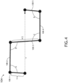
- the repeating pattern element 104 may include five repeating pattern sub-elements 108-1, 108-2, 108-3, 108-4, 108-5 (which collectively may be referred to as 108).
- a plurality of the repeating pattern elements 104 may be repeated along a linear direction to form the sequence 102.
- the repeating pattern element 104 may be a repeating component of an ARTCC boundary 102-3.
- the five sub-element 108 lines may make four vertices that have angles totaling zero degrees.
- the system 500 may include at least one computing device 502, at least one aircraft 510, at least one computing device 522, and/or at least one network 524, some or all of which may be communicatively coupled at any given time.
- the computing device 502 may be configured to obtain (e.g., receive from the computing device 522) a graphical image file, the graphical image file including an image (e.g., a flight chart image 100).
- the image may include at least one sequence 102 of repeating pattern elements 104, and each of the at least one sequence 102 may include the repeating pattern elements that are repeated along a linear direction.
- the computing device 502 may be configured to convert the graphical image file to at least one file including hardware directives that when executed cause a recreation of the image of the graphical image file to be drawn, wherein a file size of the at least one file is smaller than the graphical image file.
- the at least one file may be output by the computing device 502 and loaded onto an avionics computing device of the aircraft 510, such as a display unit computing device 512.
- the display unit computing device 512 may be configured to execute the hardware directives of the at least one file, which causes a recreation of the image of the graphical image file to be drawn on a display 514 of the display unit computing device 512.
- the at least one computing device 502 may be implemented as any suitable computing device, such as a host computing device located offboard of the aircraft 510 and/or located remotely from the aircraft 510.
- the at least one computing device 502 may include any or all of the elements, as shown in FIG. 5 .
- the computing device 502 may include at least one processor 504, at least one memory 506, and/or at least one storage 508, some or all of which may be communicatively coupled at any given time.
- the at least one processor 504 may include at least one central processing unit (CPU), at least one graphics processing unit (GPU), at least one field-programmable gate array (FPGA), at least one application specific integrated circuit (ASIC), at least one digital signal processor, at least one image processor, at least one virtual machine (VM) running on at least one processor, and/or the like configured to perform (e.g., collectively perform) any of the operations disclosed throughout.
- the at least one processor 504 may include a CPU and a GPU configured to perform (e.g., collectively perform) any of the operations disclosed throughout.
- the processor 504 may be configured to run various software applications or computer code stored (e.g., maintained) in a non-transitory computer-readable medium (e.g., memory 506 and/or storage 508) and configured to execute various instructions or operations.
- the processor 504 of the computing device 502 may be configured to perform any or all of the operations disclosed throughout.
- the processor 504 of the computing device 502 may be configured to: obtain a graphical image file (e.g., a graphical flight chart image file), the graphical image file including an image (e.g., a flight chart image 100), wherein the image includes at least one sequence 102 of repeating pattern elements 104, each of the at least one sequence 102 including the repeating pattern elements 104 that are repeated along a linear direction; and/or convert the graphical image file to at least one file including hardware directives that when executed cause a recreation of the image of the graphical image file to be drawn, wherein a file size of the at least one file is smaller than the graphical image file.
- a graphical image file e.g., a graphical flight chart image file
- the graphical image file including an image (e.g., a flight chart image 100)
- the image includes at least one sequence 102 of repeating pattern elements 104, each of the at least one sequence 102 including the repeating pattern elements 104 that are repeated along a linear direction
- the graphical image file has a set of vector graphics for each repeating pattern element 104, wherein a given set of vector graphics for each repeating pattern element 104 of the graphical image file is converted to a more compact set of vector graphics in the recreation of the image (e.g., the flight chart image 100), wherein a given more compact set of vector graphics fully defines a given repeating pattern element 104 from the graphical image file.
- each repeating pattern element 104 of the repeating pattern elements 104 is composed of repeating pattern sub-elements 108.
- the file size of the at least one file is at least 75% (e.g., at least 90%) smaller than the graphical image file.
- the graphical image file may be any suitable type of graphical image file that has at least one sequence 102 of repeated pattern elements 104.
- the graphical image file may be a portable digital file (PDF), a Joint Photographic Experts Group (JPEG) file, a Portable Network Graphics (PNG) file, a graphics interchange format (GIF) file, a tagged image file (TIFF), a Photoshop document (PSD), an encapsulated postscript (EPS) file, an Adobe Illustrator (Al) document, an Adobe Indesign Document (INDD), or a raw image format.
- PDF portable digital file
- JPEG Joint Photographic Experts Group
- PNG Portable Network Graphics
- GIF graphics interchange format
- TIFF tagged image file
- PSD Photoshop document
- EPS encapsulated postscript
- Al Adobe Illustrator
- INDD Adobe Indesign Document
- the at least one processor 504 being configured to convert the graphical image file to the at least one file comprises the at least one processor 504 being configured to: for a given sequence 102 of the at least one sequence 102 of repeating pattern elements 104, determine a length of the given sequence 102 of repeating pattern elements 104; for the given sequence 102, determine a straight-line length along the linear direction of one repeating pattern element 104 of the repeating pattern elements 104; for the given sequence, based at least on the length and the straight-line length, determine a quantity of the repeating pattern elements 104 for the given sequence 102; store repeating pattern element hardware directives that when executed cause the repeating pattern element 104 to be drawn once; and/or store binary progression hardware directives that when executed cause a binary progression of the repeating pattern element hardware directives to be called such that the given sequence 102 of repeating pattern elements 104 is drawn.
- At least one of the hardware directives includes scaling and rotational characteristics necessary for drawing the given sequence of repeating pattern elements to match a scale and angular orientation of the given sequence of repeating pattern elements in the image (e.g., the flight chart image 100) of the graphical image file.
- the at least one sequence 102 comprises the given sequence 102 and a second sequence 102, wherein the given sequence 102 of repeating pattern elements 104 meets the second sequence 102 of repeating pattern elements 104 at an angle; in such embodiments, the at least one processor being configured to convert the graphical image file to the at least one file may further comprise the at least one processor being configured to: store transient hardware directives that when executed cause a transient to be drawn where the given sequence and the second sequence meet.
- the image of the graphical image file is a flight chart image 100, and when the hardware directives are executed by a display unit computing device 512 of an aircraft 510, the recreation of the flight chart image 100 of the graphical image file is drawn on a display 514 of the display unit computing device 512.
- the at least one sequence 102 of repeating pattern elements 104 corresponds to at least one of a special use airspace (SUA) boundary 102-1, an air route traffic control center (ARTCC) boundary 102-3, an air defence identification zone (ADIZ) boundary 102-2, a longitudinal tick mark line 102-5, a latitudinal tick mark line 102-5, or a time zone boundary 102-4.
- SUVA special use airspace
- ARTCC air route traffic control center
- ADIZ air defence identification zone
- the aircraft 510 may include at least one user (e.g., flight crew and/or pilot(s)) (not shown), at least one display unit computing device 512, at least one aircraft computing device (not shown), and/or at least one user interface (not shown), some or all of which may be communicatively coupled at any given time.
- the display unit computing device 512 may be implemented as any suitable computing device, such as a primary flight display (PFD) computing device and/or a multi-function window (MFW) display computing device. As shown in FIG. 5 , the display unit computing device 512 may include at least one display 514, at least one processor 516, at least one memory 518, and/or at least one storage 520, some or all of which may be communicatively coupled at any given time.
- PFD primary flight display
- MMW multi-function window
- the at least one processor 516 may include at least one central processing unit (CPU), at least one graphics processing unit (GPU), at least one field-programmable gate array (FPGA), at least one application specific integrated circuit (ASIC), at least one digital signal processor, at least one virtual machine (VM) running on at least one processor, and/or the like configured to perform (e.g., collectively perform) any of the operations disclosed throughout.
- the at least one processor 516 may include a CPU and a GPU configured to perform (e.g., collectively perform) any of the operations disclosed throughout.
- the processor 516 may be configured to run various software applications (e.g., a PFD application, and/or an MFW application) and/or computer code stored (e.g., maintained) in a non-transitory computer-readable medium (e.g., memory 518 and/or storage 520) and configured to execute various instructions or operations.
- the processor 516 may be configured to perform any or all of the operations disclosed throughout.
- the processor 516 may be configured to: obtain the at least one file (e.g., from the computing device 502); and/or execute the hardware directives of the at least one file, which causes a recreation of the image of the graphical image file to be drawn on a display 514 of the display unit computing device 512.
- the display 514 may be configured to display the recreation of the image (e.g., a flight chart image 100) of the graphical image file.
- the at least one display unit computing device 104 for the aircraft 510 may be located offboard of the aircraft 102, for example, if a given aircraft 102 is a remotely piloted and/or managed aircraft (e.g., an unmanned aerial vehicle (UAV) or a drone aircraft).
- UAV unmanned aerial vehicle
- the computing device 522 may be any suitable computing device.
- the computing device 522 may have similar elements and functionality as the computing device 502, except that the computing device 522 may be configured to provide (e.g., via the network 524) the graphical image file to the computing device 502.
- the computing device 522 may be operated by a third-party vendor of the graphical image file.
- the processor 504 of the computing device 502 may be configured to: (a) detect a sequence 102 of repeating pattern elements 104.
- the processor 504 may be configured to: (b) create a subroutine of drawing a single repeating pattern element 104 of the image (e.g., the flight chart image 100) of the graphical image file in hardware directives, followed by a return.
- the actual drawn image of the single repeating pattern element 104 may be referred to as C0.
- the processor 504 may be configured to: (c) create a function to call the single repeating pattern element 104 (which may be referred to as C1), followed by a return.
- the processor 504 may be configured to: (d) create a function to call C1 twice (which may be referred to as C2), followed by a return.
- the processor 504 may be configured to: (e) create a function to call C2 twice (which may be referred to as C4), followed by a return.
- the processor 504 may be configured to: (f) create a function to call Cn twice (which may be referred to as C2n) as needed, storing each call location.
- the processor 504 may be configured to: (g) when the sequence 102 of repeating pattern elements 104 is found, determine a number of repeating pattern elements 104 in the sequence 102; determine a highest value of 2 n that goes into that number without exceeding the number; and create more Cn calls if the value of 2 n is greater than the available largest Cn call.
- the processor 504 may be configured to: (h) using a method for low maintenance machine code subroutine execution, add each Cn routine to a display list organization area of a hardware display list, tracking the location of each called function. To invoke hardware subroutines, the absolute address of the subroutine should be known. This address is not known on the host when the hardware directives are created, so this address should be updated by the display system at run-time.
- the processor 504 may be configured to: (i) set the scaling and rotational characteristics as necessary. Typically, a repeating pattern element 104 may be defined in horizontal orientation, but will be drawn in a non-horizontal orientation.
- the processor 504 may be configured to: (j) call the Cn functions as indirect calls within the hardware display list. This may be done as necessary to draw the required number of repeating pattern elements 104 in the sequence 102. This is a binary progression. For example, if there are 201 repeating pattern elements 104 in the sequence 102, the following calls would be made: C128, C64, C8, C1.
- the processor 504 may be configured to: (k) handle transients.
- the repeating pattern element 104 may include five repeating pattern sub-elements 108-1, 108-2, 108-3, 108-4, 108-5 (which collectively may be referred to as 108).
- a plurality of the repeating pattern elements 104 may be repeated along a linear direction to form the sequence 102.
- the repeating pattern element 104 may be a repeating component of an ARTCC boundary 102-3.
- the five sub-element 108 lines may make four vertices that have angles totaling zero degrees.
- the space required to display one-hundred (100) of the repeating pattern elements 104 in the sequence 102 would be 100 * 5 * 2 (sequence 102 length multiplied by lines in an repeating pattern element 104 multiplied by times number of instructions to draw a line), or 1000. However, using the method of some embodiments described herein, the space required to draw the same sequence 102 of 100 repeating pattern elements 104 would be 35 (a space savings of 96.5%).
- the space of 35 would include: 11 to define the repeating pattern element 104; 2 to define the subroutine C1 (call and return); 18 to define subroutines C2, C4, C8, C16, C32, C64 (3 each: 2 calls and return); and 4 calls in the hardware display list (calls to C64, C32, C4, and C2). Additionally, for example, a second sequence 102 of 100 of the repeating pattern elements 104 would cost just 4 instructions since the C1-C64 functions would already exist (a space savings of 99.6%). Referring now to FIG.
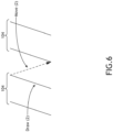
- a sequence 102 of 100 repeating pattern elements 104 which has only 4 double words (DWords) draw sequence (draw (2) + move (2) sequence), would have similar percentage space savings.
- the repeating pattern element 104 would be a line drawn at an angle and a move instruction placing the stylus at the next position to draw from.
- the repeating pattern element 104 may be any combination of line draws and moves that allow the repeating pattern to be created.
- the draw command takes 2 hardware directives and a move command takes 2 hardware directives.
- a SUA created as a repeating pattern, may take one draw and one move, or 4 total hardware directives.
- the at least one display unit computing device 512, the computing device 502, and/or the computing device 522 may be implemented as a single computing device or any number of computing devices configured to perform (e.g., collectively perform if more than one computing device) any or all of the operations disclosed throughout.
- At least one processor may be configured to perform (e.g., collectively perform) any or all of the operations disclosed throughout.
- an exemplary embodiment of a method 700 may include one or more of the following steps. Additionally, for example, some embodiments may include performing one or more instances of the method 700 iteratively, concurrently, and/or sequentially. Additionally, for example, at least some of the steps of the method 700 may be performed in parallel and/or concurrently. Additionally, in some embodiments, at least some of the steps of the method 700 may be performed non-sequentially.
- a step 702 may include obtaining, by at least one processor communicatively coupled to at least one computer readable medium, a graphical image file, the graphical image file including an image, wherein the image includes at least one sequence of repeating pattern elements, each of the at least one sequence including the repeating pattern elements that are repeated along a linear direction.
- a step 704 may include converting, by the at least one processor, the graphical image file to at least one file including hardware directives that when executed cause a recreation of the image of the graphical image file to be drawn, wherein a file size of the at least one file is smaller than the graphical image file.
- method 700 may include any of the operations disclosed throughout.
- embodiments of the inventive concepts disclosed herein may be directed to a system and a method configured to recreate an image of a graphical image file to reduce storage space, the image having repeating patterns.
- At least one non-transitory computer-readable medium may refer to as at least one non-transitory computer-readable medium (e.g., at least one computer-readable medium implemented as hardware; e.g., at least one non-transitory processor-readable medium, at least one memory (e.g., at least one nonvolatile memory, at least one volatile memory, or a combination thereof; e.g., at least one random-access memory, at least one flash memory, at least one read-only memory (ROM) (e.g., at least one electrically erasable programmable read-only memory (EEPROM)), at least one on-processor memory (e.g., at least one on-processor cache, at least one on-processor buffer, at least one on-processor flash memory, at least one on-processor EEPROM, or a combination thereof), or a combination thereof), at least one storage device (e.g., at least one hard-disk drive, at
- At least one means one or a plurality of; for example, “at least one” may comprise one, two, three, ..., one hundred, or more.
- one or more means one or a plurality of; for example, “one or more” may comprise one, two, three, ..., one hundred, or more.
- zero or more means zero, one, or a plurality of; for example, “zero or more” may comprise zero, one, two, three, ..., one hundred, or more.
- the methods, operations, and/or functionality disclosed may be implemented as sets of instructions or software readable by a device. Further, it is understood that the specific order or hierarchy of steps in the methods, operations, and/or functionality disclosed are examples of exemplary approaches. Based upon design preferences, it is understood that the specific order or hierarchy of steps in the methods, operations, and/or functionality can be rearranged while remaining within the scope of the inventive concepts disclosed herein.
- the accompanying claims may present elements of the various steps in a sample order, and are not necessarily meant to be limited to the specific order or hierarchy presented.
- embodiments of the methods according to the inventive concepts disclosed herein may include one or more of the steps described herein. Further, such steps may be carried out in any desired order and two or more of the steps may be carried out simultaneously with one another. Two or more of the steps disclosed herein may be combined in a single step, and in some embodiments, one or more of the steps may be carried out as two or more sub-steps. Further, other steps or sub-steps may be carried in addition to, or as substitutes to one or more of the steps disclosed herein.
Landscapes
- Engineering & Computer Science (AREA)
- Physics & Mathematics (AREA)
- General Physics & Mathematics (AREA)
- Theoretical Computer Science (AREA)
- Geometry (AREA)
- Computer Vision & Pattern Recognition (AREA)
- Aviation & Aerospace Engineering (AREA)
- Processing Or Creating Images (AREA)
- Image Generation (AREA)
Abstract
Description
- The space required to store flight charts in an avionics system is large, and the available space to store flight charts in those avionics systems is limited. Additionally, avionics systems typically must maintain a multitude of potentially needed flight charts for each flight, which compounds the storage capacity problem.
- In one aspect, embodiments of the inventive concepts disclosed herein are directed to a system. The system may include at least one computer readable medium and at least one processor communicatively coupled to the at least one computer readable medium. The at least one processor may be configured to: obtain a graphical image file, the graphical image file including an image, wherein the image includes at least one sequence of repeating pattern elements, each of the at least one sequence including the repeating pattern elements that are repeated along a linear direction; and convert the graphical image file to at least one file including hardware directives that when executed cause a recreation of the image of the graphical image file to be drawn, wherein a file size of the at least one file is smaller than the graphical image file.
- In a further aspect, embodiments of the inventive concepts disclosed herein are directed to a method. The method may include: obtaining, by at least one processor communicatively coupled to at least one computer readable medium, a graphical image file, the graphical image file including an image, wherein the image includes at least one sequence of repeating pattern elements, each of the at least one sequence including the repeating pattern elements that are repeated along a linear direction; and converting, by the at least one processor, the graphical image file to at least one file including hardware directives that when executed cause a recreation of the image of the graphical image file to be drawn, wherein a file size of the at least one file is smaller than the graphical image file.
- Implementations of the inventive concepts disclosed herein may be better understood when consideration is given to the following detailed description thereof. Such description makes reference to the included drawings, which are not necessarily to scale, and in which some features may be exaggerated and some features may be omitted or may be represented schematically in the interest of clarity. Like reference numerals in the drawings may represent and refer to the same or similar element, feature, or function. In the drawings:
-
FIG. 1 is a view of an exemplary embodiment of an image of an image file according to the inventive concepts disclosed herein. -
FIG. 2 is a view of an exemplary embodiment of sequences of repeating pattern elements and transients according to the inventive concepts disclosed herein. -
FIG. 3 is a view of an exemplary embodiment of sequences of repeating pattern elements and transients according to the inventive concepts disclosed herein. -
FIG. 4 is a view of an exemplary embodiment of an exemplary repeating pattern element according to the inventive concepts disclosed herein. -
FIG. 5 is a view of an exemplary embodiment of a system according to the inventive concepts disclosed herein. -
FIG. 6 is a view of an exemplary embodiment of a sequence of repeating pattern elements according to the inventive concepts disclosed herein. -
FIG. 7 is a diagram of an exemplary embodiment of a method according to the inventive concepts disclosed herein. - Before explaining at least one embodiment of the inventive concepts disclosed herein in detail, it is to be understood that the inventive concepts are not limited in their application to the details of construction and the arrangement of the components or steps or methodologies set forth in the following description or illustrated in the drawings. In the following detailed description of embodiments of the instant inventive concepts, numerous specific details are set forth in order to provide a more thorough understanding of the inventive concepts. However, it will be apparent to one of ordinary skill in the art having the benefit of the instant disclosure that the inventive concepts disclosed herein may be practiced without these specific details. In other instances, well-known features may not be described in detail to avoid unnecessarily complicating the instant disclosure. The inventive concepts disclosed herein are capable of other embodiments or of being practiced or carried out in various ways. Also, it is to be understood that the phraseology and terminology employed herein is for the purpose of description and should not be regarded as limiting.
- As used herein a letter following a reference numeral is intended to reference an embodiment of the feature or element that may be similar, but not necessarily identical, to a previously described element or feature bearing the same reference numeral (e.g., 1, 1a, 1b). Such shorthand notations are used for purposes of convenience only, and should not be construed to limit the inventive concepts disclosed herein in any way unless expressly stated to the contrary.
- Further, unless expressly stated to the contrary, "or" refers to an inclusive or and not to an exclusive or. For example, a condition A or B is satisfied by anyone of the following: A is true (or present) and B is false (or not present), A is false (or not present) and B is true (or present), and both A and B are true (or present).
- In addition, use of the "a" or "an" are employed to describe elements and components of embodiments of the instant inventive concepts. This is done merely for convenience and to give a general sense of the inventive concepts, and "a" and "an" are intended to include one or at least one and the singular also includes the plural unless it is obvious that it is meant otherwise.
- Finally, as used herein any reference to "one embodiment," or "some embodiments" means that a particular element, feature, structure, or characteristic described in connection with the embodiment is included in at least one embodiment of the inventive concepts disclosed herein. The appearances of the phrase "in some embodiments" in various places in the specification are not necessarily all referring to the same embodiment, and embodiments of the inventive concepts disclosed may include one or more of the features expressly described or inherently present herein, or any combination of sub-combination of two or more such features, along with any other features which may not necessarily be expressly described or inherently present in the instant disclosure.
- Broadly, embodiments of the inventive concepts disclosed herein may be directed to a system and a method configured to recreate an image of a graphical image file to reduce storage space, the image having repeating patterns.
- Some embodiments may provide a system and method to condense certain types of repeating information in a display system (e.g., an avionics display system) without affecting the image displayed. While some embodiments may be used by an avionics display system, other embodiments may be used in any suitable system that handles images having repeating patterns that could be condensed to reduce storage space.
- In some embodiments, a processor may detect certain patterns in an image that repeat. If these repeating patterns are detected, the processor may condense the repeating patterns such that repeating patterns are stored in a manner to significantly reduce the storage space required.
- Referring now to
FIG. 1 , an exemplary embodiment of an image (e.g., a flight chart image 100) of an image file (e.g., a graphical image file) according to the inventive concepts disclosed herein is depicted. For example, flight charts typically have many repeating patterns that traverse theflight chart image 100 in various directions. For example, theflight chart image 100 includes multiple sequences of various repeating pattern elements. For example, theflight chart image 100 includes a special use airspace (SUA) boundary 102-1, an air route traffic control center (ARTCC) boundary 102-3, an air defence identification zone (ADIZ) boundary 102-2, longitudinal and latitudinal tick mark lines 102-5, and a time zone boundary 102-4, all of which are sequences of repeating pattern elements. - Referring now to
FIGS. 2 and3 , an exemplary embodiments of exemplary sequences 102A, 102B, 102C, 102D, 102-3A (which generically may be referred to assequence 102 throughout) of repeatingpattern elements 104 andtransients 106 according to the inventive concepts disclosed herein is depicted. - As shown, in some instances, when two or
more sequences 102 meet at an intersection, a transient 106 may be drawn in the image. Thetransients 106 may be between thesequences 102. Thetransients 106 may be partial sequences or individual lines not in thesequence 102. Thetransients 106 may be drawn independently, and typically would not be condensed like thesequences 102 of repeatingpattern elements 104. For example, as shown inFIG. 3 , a closed SUA boundary's 102-3 (composed of two intersecting sequences 102-3A of repeating pattern elements 104), for instance, may havetransients 106, which may have short non-common lines at corners and/or single lines that have non-common move instructions.Transients 106 may be drawn as any line typically would be drawn, such as without using subroutines to condensesequences 102 of repeatingpattern elements 104. - Referring now to
FIG. 4 , an exemplary embodiment of exemplary repeatingpattern element 104 according to the inventive concepts disclosed herein is depicted. As exemplarily shown, the repeatingpattern element 104 may include five repeating pattern sub-elements 108-1, 108-2, 108-3, 108-4, 108-5 (which collectively may be referred to as 108). A plurality of the repeatingpattern elements 104 may be repeated along a linear direction to form thesequence 102. As exemplarily shown inFIG. 4 , the repeatingpattern element 104 may be a repeating component of an ARTCC boundary 102-3. The five sub-element 108 lines may make four vertices that have angles totaling zero degrees. - Referring now to
FIG. 5 , an exemplary embodiment of asystem 500 according to the inventive concepts disclosed herein is depicted. In some embodiments, thesystem 500 may include at least onecomputing device 502, at least oneaircraft 510, at least onecomputing device 522, and/or at least onenetwork 524, some or all of which may be communicatively coupled at any given time. - For example, the
computing device 502 may be configured to obtain (e.g., receive from the computing device 522) a graphical image file, the graphical image file including an image (e.g., a flight chart image 100). The image may include at least onesequence 102 of repeatingpattern elements 104, and each of the at least onesequence 102 may include the repeating pattern elements that are repeated along a linear direction. For example, thecomputing device 502 may be configured to convert the graphical image file to at least one file including hardware directives that when executed cause a recreation of the image of the graphical image file to be drawn, wherein a file size of the at least one file is smaller than the graphical image file. In some embodiments, the at least one file may be output by thecomputing device 502 and loaded onto an avionics computing device of theaircraft 510, such as a displayunit computing device 512. For example, the displayunit computing device 512 may be configured to execute the hardware directives of the at least one file, which causes a recreation of the image of the graphical image file to be drawn on adisplay 514 of the displayunit computing device 512. - The at least one
computing device 502 may be implemented as any suitable computing device, such as a host computing device located offboard of theaircraft 510 and/or located remotely from theaircraft 510. The at least onecomputing device 502 may include any or all of the elements, as shown inFIG. 5 . For example, thecomputing device 502 may include at least oneprocessor 504, at least onememory 506, and/or at least onestorage 508, some or all of which may be communicatively coupled at any given time. For example, the at least oneprocessor 504 may include at least one central processing unit (CPU), at least one graphics processing unit (GPU), at least one field-programmable gate array (FPGA), at least one application specific integrated circuit (ASIC), at least one digital signal processor, at least one image processor, at least one virtual machine (VM) running on at least one processor, and/or the like configured to perform (e.g., collectively perform) any of the operations disclosed throughout. For example, the at least oneprocessor 504 may include a CPU and a GPU configured to perform (e.g., collectively perform) any of the operations disclosed throughout. Theprocessor 504 may be configured to run various software applications or computer code stored (e.g., maintained) in a non-transitory computer-readable medium (e.g.,memory 506 and/or storage 508) and configured to execute various instructions or operations. Theprocessor 504 of thecomputing device 502 may be configured to perform any or all of the operations disclosed throughout. For example, theprocessor 504 of thecomputing device 502 may be configured to: obtain a graphical image file (e.g., a graphical flight chart image file), the graphical image file including an image (e.g., a flight chart image 100), wherein the image includes at least onesequence 102 of repeatingpattern elements 104, each of the at least onesequence 102 including the repeatingpattern elements 104 that are repeated along a linear direction; and/or convert the graphical image file to at least one file including hardware directives that when executed cause a recreation of the image of the graphical image file to be drawn, wherein a file size of the at least one file is smaller than the graphical image file. - In some embodiments, the graphical image file has a set of vector graphics for each
repeating pattern element 104, wherein a given set of vector graphics for eachrepeating pattern element 104 of the graphical image file is converted to a more compact set of vector graphics in the recreation of the image (e.g., the flight chart image 100), wherein a given more compact set of vector graphics fully defines a given repeatingpattern element 104 from the graphical image file. - In some embodiments, each repeating
pattern element 104 of the repeatingpattern elements 104 is composed of repeating pattern sub-elements 108. - In some embodiments, the file size of the at least one file is at least 75% (e.g., at least 90%) smaller than the graphical image file.
- In some embodiments, the graphical image file may be any suitable type of graphical image file that has at least one
sequence 102 of repeatedpattern elements 104. For example, the graphical image file may be a portable digital file (PDF), a Joint Photographic Experts Group (JPEG) file, a Portable Network Graphics (PNG) file, a graphics interchange format (GIF) file, a tagged image file (TIFF), a Photoshop document (PSD), an encapsulated postscript (EPS) file, an Adobe Illustrator (Al) document, an Adobe Indesign Document (INDD), or a raw image format. - In some embodiments, the at least one
processor 504 being configured to convert the graphical image file to the at least one file comprises the at least oneprocessor 504 being configured to: for a givensequence 102 of the at least onesequence 102 of repeatingpattern elements 104, determine a length of the givensequence 102 of repeatingpattern elements 104; for the givensequence 102, determine a straight-line length along the linear direction of one repeatingpattern element 104 of the repeatingpattern elements 104; for the given sequence, based at least on the length and the straight-line length, determine a quantity of the repeatingpattern elements 104 for the givensequence 102; store repeating pattern element hardware directives that when executed cause the repeatingpattern element 104 to be drawn once; and/or store binary progression hardware directives that when executed cause a binary progression of the repeating pattern element hardware directives to be called such that the givensequence 102 of repeatingpattern elements 104 is drawn. In some embodiments, at least one of the hardware directives includes scaling and rotational characteristics necessary for drawing the given sequence of repeating pattern elements to match a scale and angular orientation of the given sequence of repeating pattern elements in the image (e.g., the flight chart image 100) of the graphical image file. In some embodiments, the at least onesequence 102 comprises the givensequence 102 and asecond sequence 102, wherein the givensequence 102 of repeatingpattern elements 104 meets thesecond sequence 102 of repeatingpattern elements 104 at an angle; in such embodiments, the at least one processor being configured to convert the graphical image file to the at least one file may further comprise the at least one processor being configured to: store transient hardware directives that when executed cause a transient to be drawn where the given sequence and the second sequence meet. - In some embodiments, the image of the graphical image file is a
flight chart image 100, and when the hardware directives are executed by a displayunit computing device 512 of anaircraft 510, the recreation of theflight chart image 100 of the graphical image file is drawn on adisplay 514 of the displayunit computing device 512. In some embodiments, the at least onesequence 102 of repeatingpattern elements 104 corresponds to at least one of a special use airspace (SUA) boundary 102-1, an air route traffic control center (ARTCC) boundary 102-3, an air defence identification zone (ADIZ) boundary 102-2, a longitudinal tick mark line 102-5, a latitudinal tick mark line 102-5, or a time zone boundary 102-4. - In some embodiments, the
aircraft 510 may include at least one user (e.g., flight crew and/or pilot(s)) (not shown), at least one displayunit computing device 512, at least one aircraft computing device (not shown), and/or at least one user interface (not shown), some or all of which may be communicatively coupled at any given time. - The display
unit computing device 512 may be implemented as any suitable computing device, such as a primary flight display (PFD) computing device and/or a multi-function window (MFW) display computing device. As shown inFIG. 5 , the displayunit computing device 512 may include at least onedisplay 514, at least oneprocessor 516, at least onememory 518, and/or at least onestorage 520, some or all of which may be communicatively coupled at any given time. For example, the at least oneprocessor 516 may include at least one central processing unit (CPU), at least one graphics processing unit (GPU), at least one field-programmable gate array (FPGA), at least one application specific integrated circuit (ASIC), at least one digital signal processor, at least one virtual machine (VM) running on at least one processor, and/or the like configured to perform (e.g., collectively perform) any of the operations disclosed throughout. For example, the at least oneprocessor 516 may include a CPU and a GPU configured to perform (e.g., collectively perform) any of the operations disclosed throughout. Theprocessor 516 may be configured to run various software applications (e.g., a PFD application, and/or an MFW application) and/or computer code stored (e.g., maintained) in a non-transitory computer-readable medium (e.g.,memory 518 and/or storage 520) and configured to execute various instructions or operations. Theprocessor 516 may be configured to perform any or all of the operations disclosed throughout. For example, theprocessor 516 may be configured to: obtain the at least one file (e.g., from the computing device 502); and/or execute the hardware directives of the at least one file, which causes a recreation of the image of the graphical image file to be drawn on adisplay 514 of the displayunit computing device 512. Thedisplay 514 may be configured to display the recreation of the image (e.g., a flight chart image 100) of the graphical image file. - In some embodiments, the at least one display
unit computing device 104 for theaircraft 510 may be located offboard of theaircraft 102, for example, if a givenaircraft 102 is a remotely piloted and/or managed aircraft (e.g., an unmanned aerial vehicle (UAV) or a drone aircraft). - In some embodiments, the
computing device 522 may be any suitable computing device. Thecomputing device 522 may have similar elements and functionality as thecomputing device 502, except that thecomputing device 522 may be configured to provide (e.g., via the network 524) the graphical image file to thecomputing device 502. In some embodiments, thecomputing device 522 may be operated by a third-party vendor of the graphical image file. - For example, the
processor 504 of thecomputing device 502 may be configured to: (a) detect asequence 102 of repeatingpattern elements 104. Theprocessor 504 may be configured to: (b) create a subroutine of drawing a singlerepeating pattern element 104 of the image (e.g., the flight chart image 100) of the graphical image file in hardware directives, followed by a return. The actual drawn image of the singlerepeating pattern element 104 may be referred to as C0. Theprocessor 504 may be configured to: (c) create a function to call the single repeating pattern element 104 (which may be referred to as C1), followed by a return. Theprocessor 504 may be configured to: (d) create a function to call C1 twice (which may be referred to as C2), followed by a return. Theprocessor 504 may be configured to: (e) create a function to call C2 twice (which may be referred to as C4), followed by a return. Theprocessor 504 may be configured to: (f) create a function to call Cn twice (which may be referred to as C2n) as needed, storing each call location. Theprocessor 504 may be configured to: (g) when thesequence 102 of repeatingpattern elements 104 is found, determine a number of repeatingpattern elements 104 in thesequence 102; determine a highest value of 2n that goes into that number without exceeding the number; and create more Cn calls if the value of 2n is greater than the available largest Cn call. Theprocessor 504 may be configured to: (h) using a method for low maintenance machine code subroutine execution, add each Cn routine to a display list organization area of a hardware display list, tracking the location of each called function. To invoke hardware subroutines, the absolute address of the subroutine should be known. This address is not known on the host when the hardware directives are created, so this address should be updated by the display system at run-time. Theprocessor 504 may be configured to: (i) set the scaling and rotational characteristics as necessary. Typically, a repeatingpattern element 104 may be defined in horizontal orientation, but will be drawn in a non-horizontal orientation. Theprocessor 504 may be configured to: (j) call the Cn functions as indirect calls within the hardware display list. This may be done as necessary to draw the required number of repeatingpattern elements 104 in thesequence 102. This is a binary progression. For example, if there are 201repeating pattern elements 104 in thesequence 102, the following calls would be made: C128, C64, C8, C1. Theprocessor 504 may be configured to: (k) handle transients. - For example, referring again to
FIG. 4 , the repeatingpattern element 104 may include five repeating pattern sub-elements 108-1, 108-2, 108-3, 108-4, 108-5 (which collectively may be referred to as 108). A plurality of the repeatingpattern elements 104 may be repeated along a linear direction to form thesequence 102. As exemplarily shown inFIG. 4 , the repeatingpattern element 104 may be a repeating component of an ARTCC boundary 102-3. The five sub-element 108 lines may make four vertices that have angles totaling zero degrees. The space required to display one-hundred (100) of the repeatingpattern elements 104 in thesequence 102 would be 100 * 5 * 2 (sequence 102 length multiplied by lines in anrepeating pattern element 104 multiplied by times number of instructions to draw a line), or 1000. However, using the method of some embodiments described herein, the space required to draw thesame sequence 102 of 100repeating pattern elements 104 would be 35 (a space savings of 96.5%). The space of 35 would include: 11 to define the repeatingpattern element 104; 2 to define the subroutine C1 (call and return); 18 to define subroutines C2, C4, C8, C16, C32, C64 (3 each: 2 calls and return); and 4 calls in the hardware display list (calls to C64, C32, C4, and C2). Additionally, for example, asecond sequence 102 of 100 of the repeatingpattern elements 104 would cost just 4 instructions since the C1-C64 functions would already exist (a space savings of 99.6%). Referring now toFIG. 6 , in a similar way as the preceding example, asequence 102 of 100repeating pattern elements 104, which has only 4 double words (DWords) draw sequence (draw (2) + move (2) sequence), would have similar percentage space savings. For example, the repeatingpattern element 104 would be a line drawn at an angle and a move instruction placing the stylus at the next position to draw from. The repeatingpattern element 104 may be any combination of line draws and moves that allow the repeating pattern to be created. In some embodiments, the draw command takes 2 hardware directives and a move command takes 2 hardware directives. For example, a SUA, created as a repeating pattern, may take one draw and one move, or 4 total hardware directives. - In some embodiments, the at least one display
unit computing device 512, thecomputing device 502, and/or thecomputing device 522 may be implemented as a single computing device or any number of computing devices configured to perform (e.g., collectively perform if more than one computing device) any or all of the operations disclosed throughout. - At least one processor (e.g., the at least one
processor 504 and/or the at least one processor 516) may be configured to perform (e.g., collectively perform) any or all of the operations disclosed throughout. - Referring now to
FIG. 7 , an exemplary embodiment of amethod 700 according to the inventive concepts disclosed herein may include one or more of the following steps. Additionally, for example, some embodiments may include performing one or more instances of themethod 700 iteratively, concurrently, and/or sequentially. Additionally, for example, at least some of the steps of themethod 700 may be performed in parallel and/or concurrently. Additionally, in some embodiments, at least some of the steps of themethod 700 may be performed non-sequentially. - A
step 702 may include obtaining, by at least one processor communicatively coupled to at least one computer readable medium, a graphical image file, the graphical image file including an image, wherein the image includes at least one sequence of repeating pattern elements, each of the at least one sequence including the repeating pattern elements that are repeated along a linear direction. - A
step 704 may include converting, by the at least one processor, the graphical image file to at least one file including hardware directives that when executed cause a recreation of the image of the graphical image file to be drawn, wherein a file size of the at least one file is smaller than the graphical image file. - Further, the
method 700 may include any of the operations disclosed throughout. - As will be appreciated from the above, embodiments of the inventive concepts disclosed herein may be directed to a system and a method configured to recreate an image of a graphical image file to reduce storage space, the image having repeating patterns.
- As used throughout and as would be appreciated by those skilled in the art, "at least one non-transitory computer-readable medium" may refer to as at least one non-transitory computer-readable medium (e.g., at least one computer-readable medium implemented as hardware; e.g., at least one non-transitory processor-readable medium, at least one memory (e.g., at least one nonvolatile memory, at least one volatile memory, or a combination thereof; e.g., at least one random-access memory, at least one flash memory, at least one read-only memory (ROM) (e.g., at least one electrically erasable programmable read-only memory (EEPROM)), at least one on-processor memory (e.g., at least one on-processor cache, at least one on-processor buffer, at least one on-processor flash memory, at least one on-processor EEPROM, or a combination thereof), or a combination thereof), at least one storage device (e.g., at least one hard-disk drive, at least one tape drive, at least one solid-state drive, at least one flash drive, at least one readable and/or writable disk of at least one optical drive configured to read from and/or write to the at least one readable and/or writable disk, or a combination thereof), or a combination thereof).
- As used throughout, "at least one" means one or a plurality of; for example, "at least one" may comprise one, two, three, ..., one hundred, or more. Similarly, as used throughout, "one or more" means one or a plurality of; for example, "one or more" may comprise one, two, three, ..., one hundred, or more. Further, as used throughout, "zero or more" means zero, one, or a plurality of; for example, "zero or more" may comprise zero, one, two, three, ..., one hundred, or more.
- In the present disclosure, the methods, operations, and/or functionality disclosed may be implemented as sets of instructions or software readable by a device. Further, it is understood that the specific order or hierarchy of steps in the methods, operations, and/or functionality disclosed are examples of exemplary approaches. Based upon design preferences, it is understood that the specific order or hierarchy of steps in the methods, operations, and/or functionality can be rearranged while remaining within the scope of the inventive concepts disclosed herein. The accompanying claims may present elements of the various steps in a sample order, and are not necessarily meant to be limited to the specific order or hierarchy presented.
- It is to be understood that embodiments of the methods according to the inventive concepts disclosed herein may include one or more of the steps described herein. Further, such steps may be carried out in any desired order and two or more of the steps may be carried out simultaneously with one another. Two or more of the steps disclosed herein may be combined in a single step, and in some embodiments, one or more of the steps may be carried out as two or more sub-steps. Further, other steps or sub-steps may be carried in addition to, or as substitutes to one or more of the steps disclosed herein.
- From the above description, it is clear that the inventive concepts disclosed herein are well adapted to carry out the objects and to attain the advantages mentioned herein as well as those inherent in the inventive concepts disclosed herein.
Claims (15)
- A system, comprising:at least one computer readable medium (506, 508); andat least one processor (504) communicatively coupled to the at least one computer readable medium, the at least one processor configured to:obtain a graphical image file, the graphical image file including an image, wherein the image includes at least one sequence (102) of repeating pattern elements (104), each of the at least one sequence including the repeating pattern elements that are repeated along a linear direction; andconvert the graphical image file to at least one file including hardware directives that when executed cause a recreation of the image of the graphical image file to be drawn,wherein a file size of the at least one file is smaller than the graphical image file.
- The system of claim 1, wherein the graphical image file has a set of vector graphics for each repeating pattern element (104), wherein a given set of vector graphics for each repeating pattern element of the graphical image file is converted to a more compact set of vector graphics in the recreation of the image, wherein a given more compact set of vector graphics fully defines a given repeating pattern element from the graphical image file.
- The system of claim 1 or 2, wherein the file size of the at least one file is at least 75% smaller than the graphical image file.
- The system of claim 1, 2 or 3, wherein the graphical image file is a portable digital file, PDF,.
- The system of any preceding claim, wherein the at least one processor (504) being configured to convert the graphical image file to the at least one file comprises the at least one processor being configured to:for a given sequence of the at least one sequence (102) of repeating pattern elements (104), determine a length of the given sequence of repeating pattern elements;for the given sequence, determine a straight-line length along the linear direction of one repeating pattern element of the repeating pattern elements;for the given sequence, based at least on the length and the straight-line length, determine a quantity of the repeating pattern elements for the given sequence;store repeating pattern element hardware directives that when executed cause the repeating pattern element to be drawn once; andstore binary progression hardware directives that when executed cause a binary progression of the repeating pattern element hardware directives to be called such that the given sequence of repeating pattern elements is drawn.
- The system of claim 5, wherein at least one of the hardware directives includes scaling and rotational characteristics necessary for drawing the given sequence (102) of repeating pattern elements (104) to match a scale and angular orientation of the given sequence of repeating pattern elements in the image of the graphical image file.
- The system of claim 5 or 6, wherein the at least one sequence (102) comprises the given sequence and a second sequence, wherein the given sequence of repeating pattern elements (104) meets the second sequence of repeating pattern elements at an angle, wherein the at least one processor (504) being configured to convert the graphical image file to the at least one file further comprises the at least one processor being configured to:
store transient hardware directives that when executed cause a transient to be drawn where the given sequence and the second sequence meet. - The system of claim 5, 6 or 7, wherein the image of the graphical image file is a flight chart image, wherein when the hardware directives are executed by a display unit computing device (512) of an aircraft (510), the recreation of the flight chart image of the graphical image file is drawn on a display of the display unit computing device.
- The system of any of claims 5 to 8, wherein at least one of the hardware directives includes scaling and rotational characteristics necessary for drawing the given sequence (102) of repeating pattern elements (104) to match a scale and angular orientation of the given sequence of repeating pattern elements in the image of the graphical image file, wherein the at least one sequence comprises the given sequence and a second sequence, wherein the given sequence of repeating pattern elements meets the second given sequence of repeating pattern elements at an angle, wherein the at least one processor being configured to convert the graphical image file to the at least one file further comprises the at least one processor (504) being configured to:
store transient hardware directives that when executed cause a transient to be drawn where the given sequence and the second sequence meet. - The system of claim 9, wherein the at least one sequence (102) of repeating pattern elements (104) corresponds to at least one of a special use airspace, SUA, boundary, an air route traffic control center, ARTCC, boundary, an air defence identification zone, ADIZ, boundary, a longitudinal tick mark line, a latitudinal tick mark line, or a time zone boundary.
- The system of claim 2, wherein the image of the graphical image file is a flight chart image, wherein when the hardware directives are executed by a display unit computing device (512) of an aircraft (510), the recreation of the flight chart image of the graphical image is drawn on a display of the display unit computing device.
- The system of claim 11, further comprising a computing device (522) comprising the at least one computer readable medium (506, 508) and the at least one processor (504), wherein the computing device is located remotely from the aircraft.
- The system of claim 11 or 12, wherein the at least one sequence (102) of repeating pattern elements (104) corresponds to at least one of a special use airspace, SUA, boundary, an air route traffic control center, ARTCC boundary, an air defence identification zone, ADIZ, boundary, a longitudinal tick mark line, a latitudinal tick mark line, or a time zone boundary.
- The system of claim 2, wherein each repeating pattern element (104) of the repeating pattern elements is composed of repeating pattern sub-elements.
- A method, comprising:obtaining, by at least one processor communicatively coupled to at least one computer readable medium, a graphical image file, the graphical image file including an image, wherein the image includes at least one sequence of repeating pattern elements, each of the at least one sequence including the repeating pattern elements that are repeated along a linear direction; andconverting, by the at least one processor, the graphical image file to at least one file including hardware directives that when executed cause a recreation of the image of the graphical image file to be drawn,wherein a file size of the at least one file is smaller than the graphical image file.
Applications Claiming Priority (2)
| Application Number | Priority Date | Filing Date | Title |
|---|---|---|---|
| US202163278576P | 2021-11-12 | 2021-11-12 | |
| US17/525,572 US11915389B2 (en) | 2021-11-12 | 2021-11-12 | System and method for recreating image with repeating patterns of graphical image file to reduce storage space |
Publications (2)
| Publication Number | Publication Date |
|---|---|
| EP4184441A1 true EP4184441A1 (en) | 2023-05-24 |
| EP4184441B1 EP4184441B1 (en) | 2025-10-22 |
Family
ID=84332086
Family Applications (1)
| Application Number | Title | Priority Date | Filing Date |
|---|---|---|---|
| EP22207060.9A Active EP4184441B1 (en) | 2021-11-12 | 2022-11-11 | System and method for recreating image with repeating patterns of graphical image file to reduce storage space |
Country Status (2)
| Country | Link |
|---|---|
| US (1) | US11915389B2 (en) |
| EP (1) | EP4184441B1 (en) |
Citations (1)
| Publication number | Priority date | Publication date | Assignee | Title |
|---|---|---|---|---|
| WO2011036499A1 (en) * | 2009-09-28 | 2011-03-31 | Nats (Services) Limited | Aeronautical information processing |
Family Cites Families (163)
| Publication number | Priority date | Publication date | Assignee | Title |
|---|---|---|---|---|
| US3522586A (en) | 1965-08-25 | 1970-08-04 | Nippon Electric Co | Automatic character recognition apparatus |
| US3656178A (en) | 1969-09-15 | 1972-04-11 | Research Corp | Data compression and decompression system |
| JPS5242017A (en) | 1975-09-29 | 1977-04-01 | Fuji Xerox Co Ltd | Run length code processing method for facsimile signal |
| JPS61234312A (en) | 1985-04-09 | 1986-10-18 | Mitsubishi Electric Corp | Vehicle-borne navigation apparatus |
| JPS622721A (en) | 1985-06-28 | 1987-01-08 | Nec Corp | Coding and decoding device for picture signal |
| JPH0634237B2 (en) | 1986-02-24 | 1994-05-02 | 三菱電機株式会社 | Image clipping method |
| JPS6393273A (en) | 1986-10-07 | 1988-04-23 | Fuji Xerox Co Ltd | Coding device for image information |
| JPH0820862B2 (en) | 1987-02-27 | 1996-03-04 | キヤノン株式会社 | Character processor |
| US4792981A (en) | 1987-09-21 | 1988-12-20 | Am International, Inc. | Manipulation of run-length encoded images |
| US4876651A (en) | 1988-05-11 | 1989-10-24 | Honeywell Inc. | Digital map system |
| AU624205B2 (en) | 1989-01-23 | 1992-06-04 | General Electric Capital Corporation | Variable length string matcher |
| US5050230A (en) | 1989-11-29 | 1991-09-17 | Eastman Kodak Company | Hybrid residual-based hierarchical storage and display method for high resolution digital images in a multiuse environment |
| US5428692A (en) | 1991-11-18 | 1995-06-27 | Kuehl; Eberhard | Character recognition system |
| US5546572A (en) | 1991-08-28 | 1996-08-13 | Hitachi, Ltd. | Method for retrieving database of image information |
| JP3155595B2 (en) | 1992-01-24 | 2001-04-09 | キヤノン株式会社 | Encoding method and apparatus |
| US5526476A (en) | 1992-12-07 | 1996-06-11 | Fujitsu Limited | Method and apparatus for generating character patterns expressed by coordinates of a coordinate system |
| NO933205D0 (en) | 1993-09-08 | 1993-09-08 | Harald Martens | Data representation system |
| US5499382A (en) | 1993-09-20 | 1996-03-12 | Nusinov; Eugene B. | Circuit and method of bit-packing and bit-unpacking using a barrel shifter |
| US5537669A (en) | 1993-09-30 | 1996-07-16 | Kla Instruments Corporation | Inspection method and apparatus for the inspection of either random or repeating patterns |
| US5577170A (en) | 1993-12-23 | 1996-11-19 | Adobe Systems, Incorporated | Generation of typefaces on high resolution output devices |
| DE4447434A1 (en) | 1994-02-23 | 1995-08-31 | Gfr Ges Fuer Regelungstechnik | CCD sensor for reading out image zones or lines |
| US5454076A (en) | 1994-03-02 | 1995-09-26 | Vlsi Technology, Inc. | Method and apparatus for simultaneously minimizing storage and maximizing total memory bandwidth for a repeating pattern |
| US5559707A (en) | 1994-06-24 | 1996-09-24 | Delorme Publishing Company | Computer aided routing system |
| US6014133A (en) | 1996-06-14 | 2000-01-11 | Seiko Epson Corporation | Data transmitter/receiver apparatus, data transmitter, data receiver, and data compression method |
| US6275610B1 (en) * | 1996-10-16 | 2001-08-14 | Convey Corporation | File structure for scanned documents |
| WO1998043208A2 (en) | 1997-03-21 | 1998-10-01 | Newfire, Inc. | Method and apparatus for graphics processing |
| JPH10293852A (en) | 1997-04-21 | 1998-11-04 | Fuji Photo Film Co Ltd | Outline extracting method |
| US5978715A (en) | 1997-10-15 | 1999-11-02 | Dassault Aviation | Apparatus and method for aircraft display and control |
| JP2004500731A (en) | 1998-06-18 | 2004-01-08 | ソニー エレクトロニクス インク | Method and apparatus for splitting, scaling and displaying video and / or graphic images across multiple display devices |
| US6240341B1 (en) | 1999-01-18 | 2001-05-29 | Honeywell International Inc. | Flight management system (FMS) with integrated bit mapped data charts |
| JP4433236B2 (en) | 1999-12-03 | 2010-03-17 | ソニー株式会社 | Information processing apparatus, information processing method, and program recording medium |
| US6781600B2 (en) | 2000-04-14 | 2004-08-24 | Picsel Technologies Limited | Shape processor |
| CA2417763A1 (en) | 2000-08-04 | 2002-02-14 | Infoglide Corporation | System and method for comparing heterogeneous data sources |
| US6448922B1 (en) | 2000-08-24 | 2002-09-10 | Rockwell Collins, Inc. | Retrofit solution for the integration of ground-based weather radar images with on-board weather radar |
| US6856864B1 (en) | 2000-11-17 | 2005-02-15 | Honeywell International Inc. | Method and system for entering data within a flight plan entry field |
| US20020097418A1 (en) | 2001-01-19 | 2002-07-25 | Chang William Ho | Raster image processor and processing method for universal data output |
| US6823333B2 (en) | 2001-03-02 | 2004-11-23 | The United States Of America As Represented By The Administrator Of The National Aeronautics And Space Administration | System, method and apparatus for conducting a keyterm search |
| US7117089B2 (en) | 2001-03-06 | 2006-10-03 | Honeywell International Inc. | Ground runway awareness and advisory system |
| DE10128858A1 (en) | 2001-06-15 | 2003-02-13 | Heidelberger Druckmasch Ag | Process for creating trapping frames in a printed page |
| US7640098B2 (en) | 2001-07-31 | 2009-12-29 | Stenbock & Everson, Inc. | Process for generating travel plans on the internet |
| US7158141B2 (en) | 2002-01-17 | 2007-01-02 | University Of Washington | Programmable 3D graphics pipeline for multimedia applications |
| US7408552B2 (en) | 2002-02-08 | 2008-08-05 | Raytheon Company | System and method for representation of aircraft altitude using spatial size and other natural perceptual cues |
| US7039505B1 (en) | 2002-07-19 | 2006-05-02 | Avidyne Corporation | Method for digital transmission and display of weather imagery |
| US20040071351A1 (en) | 2002-10-07 | 2004-04-15 | Johan Rade | Method and system for graphics compression and display |
| US7562289B2 (en) | 2003-06-18 | 2009-07-14 | Layton Geo-Science, Inc. | Methods and systems for encoding geographic coordinates and features in a portable document format file |
| KR100501173B1 (en) | 2003-08-07 | 2005-07-18 | 에스케이 텔레콤주식회사 | Method for Displaying High-Resolution Pictures in Mobile Communication Terminal, Mobile Communication Terminal and File Format Converting System of the Pictures therefor |
| US20050091340A1 (en) | 2003-10-01 | 2005-04-28 | International Business Machines Corporation | Processing interactive content offline |
| WO2005052863A2 (en) | 2003-11-28 | 2005-06-09 | Bracco Imaging S.P.A. | Method and system for distinguishing surfaces in 3d data sets ('dividing voxels') |
| WO2005096173A1 (en) | 2004-03-30 | 2005-10-13 | Victor Company Of Japan, Limited | Digitization service manual generation method and additional data generation method |
| JP2006098250A (en) | 2004-09-30 | 2006-04-13 | Fuji Photo Film Co Ltd | Car navigation system |
| US7581036B2 (en) | 2004-10-13 | 2009-08-25 | Microsoft Corporation | Offline caching of control transactions for storage devices |
| JP4247684B2 (en) | 2005-01-19 | 2009-04-02 | ソニー株式会社 | Map display device and map display method |
| JP4266939B2 (en) | 2005-02-10 | 2009-05-27 | 株式会社ソニー・コンピュータエンタテインメント | Drawing processing apparatus and drawing data compression method |
| KR100639109B1 (en) | 2005-03-23 | 2006-10-31 | 주식회사 코아로직 | An apparatus for generating a thumbnail J.P. image, a method for generating the same, and a storage medium thereof |
| US20070067095A1 (en) | 2005-07-01 | 2007-03-22 | Honeywell International Inc. | Method and apparatus for resolving ambiguous waypoints |
| JP4728744B2 (en) | 2005-08-29 | 2011-07-20 | シャープ株式会社 | Image processing device |
| US7647179B2 (en) | 2005-08-31 | 2010-01-12 | Hilton Goldstein | System and method for coordinate mapping onto airport diagrams |
| US20070094591A1 (en) | 2005-10-24 | 2007-04-26 | Etgen Michael P | System and method for text legibility enhancement |
| JP2007133231A (en) | 2005-11-11 | 2007-05-31 | Denso Corp | Map display device and navigation device |
| US7542846B2 (en) | 2006-02-07 | 2009-06-02 | Alpine Electronics, Inc. | Navigation system utilizing XML/SVG map data converted from geographic map data and layered structure of XML/SVG map data based on administrative regions |
| WO2007114722A1 (en) | 2006-03-30 | 2007-10-11 | Intel Corporation | An optimal floating-point expression translation method based on pattern matching |
| JP2008022215A (en) | 2006-07-12 | 2008-01-31 | Matsushita Electric Ind Co Ltd | Image encoding device, image encoding method, and storage medium therefor |
| US7739622B2 (en) | 2006-10-27 | 2010-06-15 | Microsoft Corporation | Dynamic thumbnails for document navigation |
| US20080103641A1 (en) | 2006-10-31 | 2008-05-01 | Honeywell International, Inc. | Methods and apparatus for overlaying non-georeferenced symbology on a georeferenced chart |
| JP2008158765A (en) | 2006-12-22 | 2008-07-10 | Canon Inc | Information processing apparatus, information processing method, and program for causing computer to execute information processing method |
| US20080240152A1 (en) | 2007-03-27 | 2008-10-02 | Dell Products L.P. | System And Method For Communicating Data For Display On A Remote Display Device |
| US7908082B2 (en) | 2007-05-04 | 2011-03-15 | The Boeing Company | Methods and systems for displaying airport moving map information |
| US20100262318A1 (en) | 2007-05-16 | 2010-10-14 | J. Ariens & Associates, Inc. | Electronic flight bag user interface system |
| US8582919B2 (en) | 2007-09-24 | 2013-11-12 | Microsoft Corporation | Altering the appearance of a digital image using a shape |
| US20090125837A1 (en) | 2007-11-08 | 2009-05-14 | International Business Machines Corporation | Tab control with type ahead and thumbnail images |
| US8260048B2 (en) | 2007-11-14 | 2012-09-04 | Exelis Inc. | Segmentation-based image processing system |
| JP5056469B2 (en) | 2008-02-22 | 2012-10-24 | 富士通株式会社 | Image management device |
| US7948502B2 (en) | 2008-05-13 | 2011-05-24 | Mitac International Corp. | Method of displaying picture having location data and apparatus thereof |
| JP4969515B2 (en) | 2008-05-23 | 2012-07-04 | 株式会社リコー | Image forming apparatus, gradation graphic image drawing method, gradation graphic image drawing program, and recording medium |
| FR2932047B1 (en) | 2008-05-29 | 2010-08-13 | Airbus France | COMPUTER SYSTEM FOR MAINTENANCE OF A REMOTE TERMINAL AIRCRAFT |
| JP5302768B2 (en) | 2008-06-26 | 2013-10-02 | キヤノン株式会社 | Image processing apparatus and image processing method |
| US8339417B2 (en) | 2008-07-25 | 2012-12-25 | Navteq B.V. | Open area maps based on vector graphics format images |
| CN101676988B (en) | 2008-09-19 | 2011-12-28 | 威锋数位开发股份有限公司 | Method for displaying the quality of small characters in stroke-based Chinese fonts |
| KR101319342B1 (en) | 2008-11-25 | 2013-10-16 | 엘지디스플레이 주식회사 | Multi-panel display and method of driving the same |
| US8386957B2 (en) * | 2009-02-25 | 2013-02-26 | Hewlett-Packard Development Company, L.P. | Method for dynamically scaling an original background layout |
| JP5274305B2 (en) | 2009-02-27 | 2013-08-28 | キヤノン株式会社 | Image processing apparatus, image processing method, and computer program |
| US10440329B2 (en) | 2009-05-22 | 2019-10-08 | Immersive Media Company | Hybrid media viewing application including a region of interest within a wide field of view |
| US8374390B2 (en) | 2009-06-24 | 2013-02-12 | Navteq B.V. | Generating a graphic model of a geographic object and systems thereof |
| US20100328353A1 (en) | 2009-06-30 | 2010-12-30 | Solidfx Llc | Method and system for displaying an image on a display of a computing device |
| US8515658B1 (en) | 2009-07-06 | 2013-08-20 | The Boeing Company | Managing navigational chart presentation |
| CN101751449B (en) | 2009-09-16 | 2012-10-10 | 中国科学院计算技术研究所 | Spatial overlap analysis method and system used in geographic information system |
| US20110157473A1 (en) | 2009-12-30 | 2011-06-30 | Hoon Choi | Method, apparatus, and system for simultaneously previewing contents from multiple protected sources |
| US20110191014A1 (en) | 2010-02-04 | 2011-08-04 | Microsoft Corporation | Mapping interface with higher zoom level inset map |
| US8583368B1 (en) | 2010-02-17 | 2013-11-12 | The Boeing Company | Rule based depiction of minimum altitudes |
| US9430195B1 (en) * | 2010-04-16 | 2016-08-30 | Emc Corporation | Dynamic server graphics |
| US9031971B2 (en) | 2010-07-23 | 2015-05-12 | Qualcomm Incorporated | Flexible data download models for augmented reality |
| US8704732B2 (en) | 2010-09-29 | 2014-04-22 | Qualcomm Incorporated | Image synchronization for multiple displays |
| US9195637B2 (en) | 2010-11-03 | 2015-11-24 | Microsoft Technology Licensing, Llc | Proportional font scaling |
| KR101495189B1 (en) | 2011-03-25 | 2015-02-24 | 엘지전자 주식회사 | Image processing apparatus and image processing method |
| US8913080B2 (en) | 2011-05-09 | 2014-12-16 | Microsoft Corporation | Partitioning high resolution images into sub-images for display |
| CN103649904A (en) | 2011-05-10 | 2014-03-19 | Nds有限公司 | Adaptive Content Presentation |
| JP2013025331A (en) | 2011-07-14 | 2013-02-04 | Konica Minolta Business Technologies Inc | Image processing apparatus, thumbnail image creation method using the apparatus and thumbnail image creation program |
| US20130031072A1 (en) | 2011-07-25 | 2013-01-31 | Luca Passani | System and Method for using a Device Description Repository |
| US9721324B2 (en) | 2011-09-10 | 2017-08-01 | Microsoft Technology Licensing, Llc | Thumbnail zoom |
| US9489121B2 (en) | 2011-11-02 | 2016-11-08 | Microsoft Technology Licensing, Llc | Optimal display and zoom of objects and text in a document |
| CN104115108B (en) | 2012-02-16 | 2018-07-27 | 古野电气株式会社 | Information display device and display mode switching method |
| GB2504085A (en) | 2012-07-16 | 2014-01-22 | Software Ltd C | Displaying maps and data sets on image display interfaces |
| US20150070373A1 (en) | 2012-08-23 | 2015-03-12 | Google Inc. | Clarification of Zoomed Text Embedded in Images |
| US9361003B2 (en) | 2012-10-18 | 2016-06-07 | Dental Imaging Technologies Corporation | Overlay maps for navigation of intraoral images |
| US9035969B2 (en) | 2012-11-29 | 2015-05-19 | Seiko Epson Corporation | Method for multiple projector display using a GPU frame buffer |
| US9484006B2 (en) * | 2013-02-13 | 2016-11-01 | Documill Oy | Manipulation of textual content data for layered presentation |
| KR102124188B1 (en) | 2013-03-13 | 2020-06-26 | 삼성전자주식회사 | Electronic device and method for processing image |
| US10372292B2 (en) | 2013-03-13 | 2019-08-06 | Microsoft Technology Licensing, Llc | Semantic zoom-based navigation of displayed content |
| US20140282038A1 (en) | 2013-03-15 | 2014-09-18 | InTheAirNet, LLC. | Flight detail application and interactive map system and method |
| CN104063844B (en) | 2013-03-21 | 2019-01-15 | 腾讯科技(深圳)有限公司 | A kind of reduced graph generating method and system |
| US9465513B2 (en) | 2013-04-11 | 2016-10-11 | General Electric Company | Visual representation of map navigation history |
| US9002637B2 (en) | 2013-04-16 | 2015-04-07 | The Boeing Company | Systems and methods for generating a navigation chart |
| CN105144230A (en) | 2013-04-30 | 2015-12-09 | 索尼公司 | Image processing device, image processing method, and program |
| US9846534B2 (en) | 2013-06-13 | 2017-12-19 | Microsoft Technology Licensing, Llc | Inset dynamic content preview pane |
| US9939271B1 (en) | 2013-09-23 | 2018-04-10 | The Boeing Company | Enroute distance measuring tool |
| CN103645837B (en) | 2013-11-27 | 2016-08-31 | 小米科技有限责任公司 | The method and apparatus amplifying display font |
| US9718558B2 (en) | 2014-02-26 | 2017-08-01 | Honeywell International Inc. | Pilot centered system and method for decluttering aircraft displays |
| JP6268023B2 (en) | 2014-03-31 | 2018-01-24 | 日本電産サンキョー株式会社 | Character recognition device and character cutout method thereof |
| US20150324088A1 (en) | 2014-05-09 | 2015-11-12 | Lyve Minds, Inc. | Thumbnail image creation |
| US9921721B2 (en) | 2014-08-08 | 2018-03-20 | Google Llc | Navigation interfaces for ebooks |
| KR20160030701A (en) | 2014-09-11 | 2016-03-21 | 삼성전자주식회사 | Host divice transmitting print data to printer and method for rendering print data by host device |
| US10210246B2 (en) | 2014-09-26 | 2019-02-19 | Oracle International Corporation | Techniques for similarity analysis and data enrichment using knowledge sources |
| US20160093080A1 (en) | 2014-09-30 | 2016-03-31 | Microsoft Technology Licensing, Llc | Optimizing the Legibility of Displayed Text |
| US10001376B1 (en) | 2015-02-19 | 2018-06-19 | Rockwell Collins, Inc. | Aircraft position monitoring system and method |
| US9443433B1 (en) | 2015-04-23 | 2016-09-13 | The Boeing Company | Method and system to monitor for conformance to a traffic control instruction |
| US9858823B1 (en) | 2015-06-09 | 2018-01-02 | Rockwell Collins, Inc. | Interactive flight plan |
| US10061480B1 (en) | 2015-07-28 | 2018-08-28 | Rockwell Collins, Inc. | Navigation chart information generating and presenting system, device, and method |
| US11106329B2 (en) | 2015-09-18 | 2021-08-31 | Honeywell International Inc. | Flight deck display systems and methods for generating cockpit displays including dynamic taxi turnoff icons |
| US9639309B1 (en) | 2015-10-14 | 2017-05-02 | Kyocera Document Solutions Inc. | Image conversion methods |
| US20170223227A1 (en) | 2016-01-29 | 2017-08-03 | Kabushiki Kaisha Toshiba | Dynamic font size management system and method for multifunction devices |
| US9818051B2 (en) | 2016-01-29 | 2017-11-14 | Ricoh Company, Ltd. | Rotation and clipping mechanism |
| US10489489B2 (en) | 2016-03-09 | 2019-11-26 | Adobe Inc. | Automatically classifying and presenting digital fonts |
| CN107239786B (en) | 2016-03-29 | 2022-01-11 | 阿里巴巴集团控股有限公司 | Character recognition method and device |
| EP3243668B1 (en) * | 2016-05-10 | 2020-07-15 | Agfa Nv | Manufacturing of a security document |
| US9781294B1 (en) * | 2016-08-09 | 2017-10-03 | Xerox Corporation | System and method for rendering micro gloss effect image patterns on a recording medium |
| US10108883B2 (en) | 2016-10-28 | 2018-10-23 | Intuit Inc. | Image quality assessment and improvement for performing optical character recognition |
| IL248975B2 (en) | 2016-11-14 | 2023-05-01 | Israel Aerospace Ind Ltd | System and method for auto-execution of aircraft check lists |
| US20180181646A1 (en) | 2016-12-26 | 2018-06-28 | Infosys Limited | System and method for determining identity relationships among enterprise data entities |
| JP2018147259A (en) | 2017-03-06 | 2018-09-20 | キヤノン株式会社 | Information processing device, program, storage medium, and information processing method |
| WO2018183994A1 (en) | 2017-03-31 | 2018-10-04 | Area 2601, LLC | Computer-based systems and methods for facilitating aircraft approach |
| CN107402734A (en) | 2017-07-25 | 2017-11-28 | 浪潮金融信息技术有限公司 | A kind of method that text definition is automatically adjusted with screen resolution |
| US10417991B2 (en) | 2017-08-18 | 2019-09-17 | Microsoft Technology Licensing, Llc | Multi-display device user interface modification |
| EP3662666B1 (en) | 2017-09-08 | 2024-08-07 | HFI Innovation Inc. | Methods and apparatuses of processing pictures in an image or video coding system |
| US11106339B2 (en) * | 2017-09-19 | 2021-08-31 | Adobe Inc. | Designing and resizing graphical user interfaces |
| US10095925B1 (en) | 2017-12-18 | 2018-10-09 | Capital One Services, Llc | Recognizing text in image data |
| US10459670B2 (en) | 2018-01-15 | 2019-10-29 | Lucid Dream Software, Inc. | Methods, systems, apparatuses and devices for facilitating printing of a digital image based on image splitting |
| US10446113B2 (en) | 2018-01-30 | 2019-10-15 | ForeFlight LLC | Method and system for inversion of raster images |
| US10170010B1 (en) | 2018-06-07 | 2019-01-01 | Rockwell Collins, Inc. | Display of traffic overlaid on aeronautical chart |
| US11580166B2 (en) | 2018-06-13 | 2023-02-14 | Oracle International Corporation | Regular expression generation using span highlighting alignment |
| CN109325083B (en) | 2018-08-03 | 2021-01-26 | 江苏联旺信息科技有限公司 | Aviation flight image map loading method, aviation flight image map loading software and aerial photographing device |
| GB2577478B (en) | 2018-09-06 | 2021-03-10 | Maritech Development Ltd | A method of creating map tiles which comprise vessel information |
| CN110906938A (en) | 2018-09-14 | 2020-03-24 | 上海擎感智能科技有限公司 | Map navigation query method, system, medium, and apparatus |
| CN111510642A (en) | 2019-01-31 | 2020-08-07 | 中强光电股份有限公司 | Display system, display method for display system, and display device |
| JP2020201649A (en) | 2019-06-07 | 2020-12-17 | トヨタ自動車株式会社 | Map generation device, map generation method and computer program for map generation |
| WO2021003294A1 (en) * | 2019-07-01 | 2021-01-07 | Digimarc Corporation | Watermarking arrangements permitting vector graphics editing |
| EP3772030A1 (en) | 2019-08-01 | 2021-02-03 | Honeywell International Inc. | Systems and methods to utilize flight monitoring data |
| US20210056251A1 (en) | 2019-08-22 | 2021-02-25 | Educational Vision Technologies, Inc. | Automatic Data Extraction and Conversion of Video/Images/Sound Information from a Board-Presented Lecture into an Editable Notetaking Resource |
| US11087123B2 (en) | 2019-08-24 | 2021-08-10 | Kira Inc. | Text extraction, in particular table extraction from electronic documents |
| CN110516221B (en) | 2019-08-29 | 2021-07-30 | 企查查科技有限公司 | Method, equipment and storage medium for extracting chart data in PDF document |
| CN110727747B (en) | 2019-09-02 | 2022-03-15 | 湖北大学 | Paper map rapid vectorization method and system based on longitude and latitude recognition |
| US11061563B1 (en) | 2020-01-06 | 2021-07-13 | Rockwell Collins, Inc. | Interactive charts system and method |
| US20210225181A1 (en) | 2020-01-20 | 2021-07-22 | Honeywell International Inc. | Display systems and methods for providing ground traffic collison threat awareness |
| US20230154338A1 (en) | 2021-11-12 | 2023-05-18 | Rockwell Collins, Inc. | Tool to facilitate customer generated chart databases for use with a certified avionics system |
-
2021
- 2021-11-12 US US17/525,572 patent/US11915389B2/en active Active
-
2022
- 2022-11-11 EP EP22207060.9A patent/EP4184441B1/en active Active
Patent Citations (1)
| Publication number | Priority date | Publication date | Assignee | Title |
|---|---|---|---|---|
| WO2011036499A1 (en) * | 2009-09-28 | 2011-03-31 | Nats (Services) Limited | Aeronautical information processing |
Non-Patent Citations (2)
| Title |
|---|
| NEUPANE PRASANGA ET AL: "Intelligent Autonomous Systems 13", vol. 1179, 13 August 2020 (2020-08-13), Cham, pages 92 - 102, XP093038266, ISSN: 2194-5357, ISBN: 978-3-319-08338-4, Retrieved from the Internet <URL:http://link.springer.com/content/pdf/10.1007/978-3-030-49336-3_10> DOI: 10.1007/978-3-030-49336-3_10 * |
| YANG Y. ET AL: "VECTORIZATION OF LINEAR FEATURES IN SCANNED TOPOGRAPHIC MAPS USING ADAPTIVE IMAGE SEGMENTATION AND SEQUENTIAL LINE TRACKING", THE INTERNATIONAL ARCHIVES OF THE PHOTOGRAMMETRY, REMOTE SENSING AND SPATIAL INFORMATION SCIENCES, vol. XXXIX-B4, 25 August 2012 (2012-08-25), pages 103 - 108, XP093038313, DOI: 10.5194/isprsarchives-XXXIX-B4-103-2012 * |
Also Published As
| Publication number | Publication date |
|---|---|
| EP4184441B1 (en) | 2025-10-22 |
| US20230153947A1 (en) | 2023-05-18 |
| US11915389B2 (en) | 2024-02-27 |
Similar Documents
| Publication | Publication Date | Title |
|---|---|---|
| JP6445016B2 (en) | Vehicle user interface adaptation | |
| EP4181400B1 (en) | Tool to facilitate customer generated chart databases for use with a certified avionics system | |
| US20200372812A1 (en) | Method and system for generating aerial imaging flight path | |
| CN106054920A (en) | Unmanned aerial vehicle flight path planning method and device | |
| US20200326709A1 (en) | Method and device for controlling reset of gimbal, gimbal, and unmanned aerial vehicle | |
| CN110570692B (en) | Unmanned aerial vehicle air route detection method and device | |
| KR20210102889A (en) | Planning method, apparatus, control terminal and storage medium of survey and mapping sample points | |
| EP4184441B1 (en) | System and method for recreating image with repeating patterns of graphical image file to reduce storage space | |
| US10249062B2 (en) | System and method for image view binding optimization | |
| CN111210516A (en) | A software platform for integrated display control of avionics equipment | |
| JP2023164746A (en) | Work plan making system | |
| CN109304870B (en) | 3D printing method and device | |
| US11651568B2 (en) | Data selection for spatial reconstruction | |
| CN118674880A (en) | A method and device for generating a three-dimensional texture model of a city based on composite data | |
| US10521663B1 (en) | Iterative image position determination | |
| Stødle et al. | High-performance visualisation of UAV sensor and image data with raster maps and topography in 3D | |
| US11172125B2 (en) | Method and a system to provide aerial visualization of large landscape area | |
| US11954770B2 (en) | System and method for recreating graphical image using character recognition to reduce storage space | |
| EP4180769A1 (en) | System and method for providing more readable font characters in size adjusting avionics charts | |
| JP6934646B1 (en) | Flight restriction area setting method, waypoint setting method and management server, information processing system, program | |
| KR102883165B1 (en) | Apparatus for storing data and method thereof | |
| KR20190067528A (en) | Platform-based electronic navigation chart sharing system | |
| US11543265B2 (en) | Third-party accessible application programming interface for generating 3D symbology | |
| CN110570691B (en) | Unmanned aerial vehicle route determining method and device | |
| EP4191205A2 (en) | System and method for determining geographic information of airport terminal chart and converting graphical image file to hardware directives for display unit |
Legal Events
| Date | Code | Title | Description |
|---|---|---|---|
| PUAI | Public reference made under article 153(3) epc to a published international application that has entered the european phase |
Free format text: ORIGINAL CODE: 0009012 |
|
| STAA | Information on the status of an ep patent application or granted ep patent |
Free format text: STATUS: THE APPLICATION HAS BEEN PUBLISHED |
|
| AK | Designated contracting states |
Kind code of ref document: A1 Designated state(s): AL AT BE BG CH CY CZ DE DK EE ES FI FR GB GR HR HU IE IS IT LI LT LU LV MC ME MK MT NL NO PL PT RO RS SE SI SK SM TR |
|
| STAA | Information on the status of an ep patent application or granted ep patent |
Free format text: STATUS: REQUEST FOR EXAMINATION WAS MADE |
|
| 17P | Request for examination filed |
Effective date: 20231121 |
|
| RBV | Designated contracting states (corrected) |
Designated state(s): AL AT BE BG CH CY CZ DE DK EE ES FI FR GB GR HR HU IE IS IT LI LT LU LV MC ME MK MT NL NO PL PT RO RS SE SI SK SM TR |
|
| GRAP | Despatch of communication of intention to grant a patent |
Free format text: ORIGINAL CODE: EPIDOSNIGR1 |
|
| STAA | Information on the status of an ep patent application or granted ep patent |
Free format text: STATUS: GRANT OF PATENT IS INTENDED |
|
| INTG | Intention to grant announced |
Effective date: 20250610 |
|
| RIN1 | Information on inventor provided before grant (corrected) |
Inventor name: NANDAKUMAR, SRINATH Inventor name: KOVACH, REED A. Inventor name: WONG, JASON L. Inventor name: MILLER, TODD E. Inventor name: PETERS, KYLE R. Inventor name: HENRY, JEFF M. |
|
| GRAS | Grant fee paid |
Free format text: ORIGINAL CODE: EPIDOSNIGR3 |
|
| GRAA | (expected) grant |
Free format text: ORIGINAL CODE: 0009210 |
|
| STAA | Information on the status of an ep patent application or granted ep patent |
Free format text: STATUS: THE PATENT HAS BEEN GRANTED |
|
| AK | Designated contracting states |
Kind code of ref document: B1 Designated state(s): AL AT BE BG CH CY CZ DE DK EE ES FI FR GB GR HR HU IE IS IT LI LT LU LV MC ME MK MT NL NO PL PT RO RS SE SI SK SM TR |
|
| REG | Reference to a national code |
Ref country code: CH Ref legal event code: F10 Free format text: ST27 STATUS EVENT CODE: U-0-0-F10-F00 (AS PROVIDED BY THE NATIONAL OFFICE) Effective date: 20251022 Ref country code: GB Ref legal event code: FG4D |
|
| REG | Reference to a national code |
Ref country code: DE Ref legal event code: R096 Ref document number: 602022023394 Country of ref document: DE |
|
| REG | Reference to a national code |
Ref country code: IE Ref legal event code: FG4D |
|
| PGFP | Annual fee paid to national office [announced via postgrant information from national office to epo] |
Ref country code: DE Payment date: 20251022 Year of fee payment: 4 |
|
| PGFP | Annual fee paid to national office [announced via postgrant information from national office to epo] |
Ref country code: AT Payment date: 20260113 Year of fee payment: 4 |
|
| PGFP | Annual fee paid to national office [announced via postgrant information from national office to epo] |
Ref country code: FR Payment date: 20251119 Year of fee payment: 4 |
|
| REG | Reference to a national code |
Ref country code: NL Ref legal event code: MP Effective date: 20251022 |
|
| PG25 | Lapsed in a contracting state [announced via postgrant information from national office to epo] |
Ref country code: NL Free format text: LAPSE BECAUSE OF FAILURE TO SUBMIT A TRANSLATION OF THE DESCRIPTION OR TO PAY THE FEE WITHIN THE PRESCRIBED TIME-LIMIT Effective date: 20251022 |
|
| PG25 | Lapsed in a contracting state [announced via postgrant information from national office to epo] |
Ref country code: ES Free format text: LAPSE BECAUSE OF FAILURE TO SUBMIT A TRANSLATION OF THE DESCRIPTION OR TO PAY THE FEE WITHIN THE PRESCRIBED TIME-LIMIT Effective date: 20251022 |
|
| REG | Reference to a national code |
Ref country code: LT Ref legal event code: MG9D |
|
| PG25 | Lapsed in a contracting state [announced via postgrant information from national office to epo] |
Ref country code: NO Free format text: LAPSE BECAUSE OF FAILURE TO SUBMIT A TRANSLATION OF THE DESCRIPTION OR TO PAY THE FEE WITHIN THE PRESCRIBED TIME-LIMIT Effective date: 20260122 |
|
| PG25 | Lapsed in a contracting state [announced via postgrant information from national office to epo] |
Ref country code: FI Free format text: LAPSE BECAUSE OF FAILURE TO SUBMIT A TRANSLATION OF THE DESCRIPTION OR TO PAY THE FEE WITHIN THE PRESCRIBED TIME-LIMIT Effective date: 20251022 Ref country code: HR Free format text: LAPSE BECAUSE OF FAILURE TO SUBMIT A TRANSLATION OF THE DESCRIPTION OR TO PAY THE FEE WITHIN THE PRESCRIBED TIME-LIMIT Effective date: 20251022 Ref country code: AT Free format text: LAPSE BECAUSE OF FAILURE TO SUBMIT A TRANSLATION OF THE DESCRIPTION OR TO PAY THE FEE WITHIN THE PRESCRIBED TIME-LIMIT Effective date: 20251022 |
|
| REG | Reference to a national code |
Ref country code: AT Ref legal event code: MK05 Ref document number: 1849863 Country of ref document: AT Kind code of ref document: T Effective date: 20251022 |
|
| PG25 | Lapsed in a contracting state [announced via postgrant information from national office to epo] |
Ref country code: RS Free format text: LAPSE BECAUSE OF FAILURE TO SUBMIT A TRANSLATION OF THE DESCRIPTION OR TO PAY THE FEE WITHIN THE PRESCRIBED TIME-LIMIT Effective date: 20260122 |
|
| PG25 | Lapsed in a contracting state [announced via postgrant information from national office to epo] |
Ref country code: IS Free format text: LAPSE BECAUSE OF FAILURE TO SUBMIT A TRANSLATION OF THE DESCRIPTION OR TO PAY THE FEE WITHIN THE PRESCRIBED TIME-LIMIT Effective date: 20260222 |
|
| PG25 | Lapsed in a contracting state [announced via postgrant information from national office to epo] |
Ref country code: PT Free format text: LAPSE BECAUSE OF FAILURE TO SUBMIT A TRANSLATION OF THE DESCRIPTION OR TO PAY THE FEE WITHIN THE PRESCRIBED TIME-LIMIT Effective date: 20260223 |
|
| PG25 | Lapsed in a contracting state [announced via postgrant information from national office to epo] |
Ref country code: PL Free format text: LAPSE BECAUSE OF FAILURE TO SUBMIT A TRANSLATION OF THE DESCRIPTION OR TO PAY THE FEE WITHIN THE PRESCRIBED TIME-LIMIT Effective date: 20251022 |
|
| PG25 | Lapsed in a contracting state [announced via postgrant information from national office to epo] |
Ref country code: LV Free format text: LAPSE BECAUSE OF FAILURE TO SUBMIT A TRANSLATION OF THE DESCRIPTION OR TO PAY THE FEE WITHIN THE PRESCRIBED TIME-LIMIT Effective date: 20251022 |
|
| PG25 | Lapsed in a contracting state [announced via postgrant information from national office to epo] |
Ref country code: BG Free format text: LAPSE BECAUSE OF FAILURE TO SUBMIT A TRANSLATION OF THE DESCRIPTION OR TO PAY THE FEE WITHIN THE PRESCRIBED TIME-LIMIT Effective date: 20251022 |