EP4184183B1 - Detection of open or closed state of a circuit breaker - Google Patents
Detection of open or closed state of a circuit breaker Download PDFInfo
- Publication number
- EP4184183B1 EP4184183B1 EP22207560.8A EP22207560A EP4184183B1 EP 4184183 B1 EP4184183 B1 EP 4184183B1 EP 22207560 A EP22207560 A EP 22207560A EP 4184183 B1 EP4184183 B1 EP 4184183B1
- Authority
- EP
- European Patent Office
- Prior art keywords
- meter
- test signal
- voltage level
- phase
- injection
- Prior art date
- Legal status (The legal status is an assumption and is not a legal conclusion. Google has not performed a legal analysis and makes no representation as to the accuracy of the status listed.)
- Active
Links
- 238000001514 detection method Methods 0.000 title claims description 44
- 238000002347 injection Methods 0.000 claims description 44
- 239000007924 injection Substances 0.000 claims description 44
- 230000007935 neutral effect Effects 0.000 claims description 39
- 238000011144 upstream manufacturing Methods 0.000 claims description 39
- 239000003990 capacitor Substances 0.000 claims description 38
- 239000004020 conductor Substances 0.000 claims description 36
- 238000009434 installation Methods 0.000 claims description 11
- 238000005259 measurement Methods 0.000 claims description 11
- 238000004590 computer program Methods 0.000 claims description 4
- 230000002452 interceptive effect Effects 0.000 claims 1
- 238000000034 method Methods 0.000 claims 1
- 238000010616 electrical installation Methods 0.000 description 4
- 230000005611 electricity Effects 0.000 description 3
- 238000001914 filtration Methods 0.000 description 3
- 230000009897 systematic effect Effects 0.000 description 2
- 238000003491 array Methods 0.000 description 1
- 238000004364 calculation method Methods 0.000 description 1
- 230000000295 complement effect Effects 0.000 description 1
- 230000000694 effects Effects 0.000 description 1
- 230000003071 parasitic effect Effects 0.000 description 1
Images
Classifications
-
- G—PHYSICS
- G01—MEASURING; TESTING
- G01R—MEASURING ELECTRIC VARIABLES; MEASURING MAGNETIC VARIABLES
- G01R31/00—Arrangements for testing electric properties; Arrangements for locating electric faults; Arrangements for electrical testing characterised by what is being tested not provided for elsewhere
- G01R31/327—Testing of circuit interrupters, switches or circuit-breakers
- G01R31/3271—Testing of circuit interrupters, switches or circuit-breakers of high voltage or medium voltage devices
- G01R31/3272—Apparatus, systems or circuits therefor
- G01R31/3274—Details related to measuring, e.g. sensing, displaying or computing; Measuring of variables related to the contact pieces, e.g. wear, position or resistance
-
- G—PHYSICS
- G01—MEASURING; TESTING
- G01R—MEASURING ELECTRIC VARIABLES; MEASURING MAGNETIC VARIABLES
- G01R22/00—Arrangements for measuring time integral of electric power or current, e.g. electricity meters
- G01R22/06—Arrangements for measuring time integral of electric power or current, e.g. electricity meters by electronic methods
- G01R22/061—Details of electronic electricity meters
- G01R22/068—Arrangements for indicating or signaling faults
-
- G—PHYSICS
- G01—MEASURING; TESTING
- G01R—MEASURING ELECTRIC VARIABLES; MEASURING MAGNETIC VARIABLES
- G01R31/00—Arrangements for testing electric properties; Arrangements for locating electric faults; Arrangements for electrical testing characterised by what is being tested not provided for elsewhere
- G01R31/327—Testing of circuit interrupters, switches or circuit-breakers
-
- G—PHYSICS
- G01—MEASURING; TESTING
- G01R—MEASURING ELECTRIC VARIABLES; MEASURING MAGNETIC VARIABLES
- G01R19/00—Arrangements for measuring currents or voltages or for indicating presence or sign thereof
- G01R19/0084—Arrangements for measuring currents or voltages or for indicating presence or sign thereof measuring voltage only
-
- G—PHYSICS
- G01—MEASURING; TESTING
- G01R—MEASURING ELECTRIC VARIABLES; MEASURING MAGNETIC VARIABLES
- G01R31/00—Arrangements for testing electric properties; Arrangements for locating electric faults; Arrangements for electrical testing characterised by what is being tested not provided for elsewhere
- G01R31/327—Testing of circuit interrupters, switches or circuit-breakers
- G01R31/3271—Testing of circuit interrupters, switches or circuit-breakers of high voltage or medium voltage devices
- G01R31/3275—Fault detection or status indication
Definitions
- the invention relates to the field of electric meters.
- Modern electricity meters are so-called “intelligent” electronic meters which are of course designed to measure electrical energy supplied by a distributor to an electrical installation via a distribution network, but which are also capable of performing a certain number of additional functions: rate management by receiving orders, remote reading and programming, remote customer information, etc.
- Some electric meters include a cut-off device (located inside the electric meter), which makes it possible to selectively connect and disconnect, remotely or from the electric meter, the electrical installation from the distribution network.
- the cutting device is used in particular to remotely cut off or restore the power supply to the installation in the event, for example, of termination of the subscription or non-compliance with the subscription contract.
- circuit breaker located outside and downstream of the electricity meter (i.e. on the installation side).
- the circuit breaker which can be activated by the subscriber, has the role of protecting the installation by opening when an overvoltage, resulting for example from a short circuit between a phase and the neutral, occurs on the network of distribution.
- the object of the invention is to detect from inside the meter, in a reliable and robust manner, the open or closed state of the circuit breaker while the meter cut-off member is open.
- the detection circuit of the meter according to the invention therefore makes it possible to detect, by injecting a test signal on the phase conductor, whether the circuit breaker is open or closed when the cut-off member is open.
- the difference in the intermediate voltage level, between the open circuit breaker and closed circuit breaker cases, is typically of the order of V or hundreds of mV, and is therefore easily measurable.
- the detection is less sensitive to noise and therefore more reliable and more robust than in the prior art.
- the injection component being a first capacitor integrated in a first high-pass filter making it possible to filter parasitic signals coming from the distribution network.
- the at least one generator component comprises a generator module arranged to produce the test signal with the predetermined voltage level, and a driver forming a current source arranged to ensure that the test signal is generated with a level of sufficient current to maintain, at the output of the at least one generator component, a voltage level equal to the predetermined voltage level.
- the measurement chain successively comprises, from upstream to downstream, a second high-pass filter, an envelope detector and a low-pass filter.
- the injection chain being arranged to, when the cut-off member is open, inject the test signal periodically, for a predetermined duration.
- the injection chain being arranged to, when the cut-off member is open, inject the test signal continuously.
- test signal is an alternating signal having a frequency at least one hundred times greater than a frequency of a phase current circulating on the phase of the distribution network.
- phase conductor is connected to an electrical mass of the meter upstream of the cutting member, the meter further comprising a second capacitor positioned upstream of the switching member. cut-off and having a first terminal connected to the neutral conductor and a second terminal connected to the phase conductor.
- the injection component being a first capacitor
- the injection chain comprising a resistor mounted between the first capacitor and an output of at least one generator component
- the injection component being a first capacitor
- the injection chain comprising a resistor mounted between the first capacitor and an output of at least one generator component
- a computer-readable recording medium is provided, on which the computer program as previously described is recorded.
- the meter 1 is a single-phase meter, which is intended to measure electrical energy supplied to the electrical installation 2 of a subscriber by a distribution network 3.
- Distribution network 3 includes a phase 4 and a neutral 5.
- Circuit breaker 6 is positioned between meter 1 and installation 2.
- Meter 1 comprises an upstream phase port P connected to phase 4 and an upstream neutral port N connected to neutral 5.
- Meter 1 further comprises a downstream phase port P' and a downstream neutral port N'.
- the downstream phase port P' and the downstream neutral port N' of meter 1 are connected to installation 2 respectively via a switch 8 and a switch 9 integrated into circuit breaker 6.
- the meter 1 further comprises a phase conductor 10, which is connected to phase 4 of the distribution network 3 via the upstream phase port P, and which is connected to the circuit breaker 6 via the downstream phase port P'.
- the meter 1 further comprises a neutral conductor 11, which is connected to the neutral 5 via the upstream neutral port N, and which is connected to the circuit breaker 6 via the downstream neutral port N'.
- the counter 1 further comprises a cut-off member 12 comprising a switch 13 mounted on the phase conductor 10.
- the meter 1 includes an electrical ground 14.
- the phase conductor 10 is connected to the ground 14 near the upstream phase port P and upstream of the cutoff member 12. This grounding of the phase conductor 10 s 'explained by the fact that the meter 1 includes a current sensor, making it possible to measure the phase current circulating on phase 4, which is a shunt (not shown here), positioned on the phase conductor 10 upstream of the cutoff member 12. Without grounding the phase conductor 10, the voltage across the shunt would be of the order of that present between the phase and the neutral of the network 3, and therefore very high.
- phase conductor 10 makes it possible to obtain a low voltage across the shunt (here of the order of 3.3V maximum after the application of a gain knowing that the voltage across a shunt is of the order of 15 to 20mV for a current passing through it of 100A effective), which corresponds to the acceptable voltage range at the input of the metrology microcontroller (not shown here) integrated into the meter 1.
- Counter 1 also includes a detection circuit.
- the detection circuit includes an injection chain 15, a measurement chain 16, and a processing component.
- chain we mean a succession of one or more components (or functional modules) connected in series.
- the injection chain 15 comprises at least one generator component (in this case two generator components), a resistor R, and an injection component (in this case a first capacitor C1).
- the two generator components include a generator module 20, integrated into the application microcontroller 17 of counter 1, and a driver 21.
- the microcontroller 17 includes a PWM output 22 (for Pulse Width Modulation ) .
- the output of generator module 20 is connected to PWM output 22.
- Driver 21 here is an amplifier mounted as a follower. Output 22 of microcontroller 17 is connected to the non-inverting input of driver 21. The inverting input of driver 21 is connected to the output of driver 21.
- the output of driver 21 is connected to a first terminal of the resistor R, a second terminal of which is connected to a first terminal of the first capacitor C1.
- the second terminal of the first capacitor C1 is connected to the phase conductor 10 downstream of the cutoff member 12.
- the resistor R has a resistance value which is here equal to 1k ⁇ .
- the first capacitor C1 has a capacitance value which is here equal to 47nF.
- the first capacitor C1 is integrated into a first high-pass filter (filter R-C1) making it possible to filter spurious signals coming from the distribution network 3.
- the measurement chain 16 comprises the following elements, arranged successively from upstream to downstream: a second high-pass filter 24, an analog-digital converter (ADC) 25, an envelope detector 26 and a low-pass filter 27.
- ADC analog-digital converter
- the second high-pass filter 24 is therefore here an analog filter while the envelope detector 26 and the low-pass filter 27 are digital modules.
- the ADC 25, the envelope detector 26 and the low-pass filter 27 are here integrated into the microcontroller 17.
- the processing component of the detection circuit is here the microcontroller 17.
- the microcontroller 17 is adapted to execute program instructions to implement the detection method which will be described.
- the program is stored in a memory 28, which is integrated into or connected to the microcontroller 17.
- the counter 1 further comprises a second capacitor C2 positioned upstream of the cutoff member 12 and having a first terminal connected to the neutral conductor 11 and a second terminal connected to the phase conductor 10.
- the second capacitor C2 has a value of capacity typically equal to that of the first capacitor C1, that is to say here at 47nF.
- the second capacitor C2 thus positioned between the neutral conductor 11 and the phase conductor 10, makes it possible to constitute a controlled mass return path for the measurements carried out during detection (remember that the cut-off member 12 is open during detection).
- a test signal St is injected periodically and for a predetermined duration by the injection chain 15.
- the period is for example equal to 1s and the predetermined duration to 500ms, i.e. that is to say that, when the cutoff member 12 is open, the test signal St is injected for 500ms, every 1s.
- the injection chain 15 could, when the cutoff member 12 is open, inject the test signal St continuously.
- the generator module 20 of the microcontroller 17 produces the test signal St and applies it to output 22.
- the test signal St is here a square (or rectangular) alternating signal having a frequency advantageously at least one hundred times higher than the frequency of the phase current circulating on phase 4 of the distribution network 3.
- the frequency of the phase current is equal to 50Hz
- the frequency of the test signal St is equal to 10kHz.
- the test signal St is generated by the microcontroller 17 with a predetermined voltage level, here equal to 3.3V (peak to peak).
- test signal St is applied to the non-inverting input of driver 21 and is therefore reproduced on the output of driver 21.
- the driver 21 forms a current source providing a complementary current making it possible to ensure that the test signal St is generated with a current level sufficient to maintain, at the output of the generating components (that is to say here at the output of the driver 21), a voltage level equal to the predetermined voltage level.
- the driver 21 is necessary here, because the different elements constituting and connected to the injection chain 15 “draw” current that the microcontroller 17 is not capable of providing alone.
- the resistance R limits the current.
- the first capacitor C1 makes it possible to inject the test signal St, produced by the microcontroller 17 and the driver 21, onto the phase conductor 10 downstream of the cutoff member 12.
- the measuring chain 16 makes it possible to measure, at a measuring point Pm of the injection chain 15 located between the at least one generator component and the injection component, an intermediate voltage level of the test signal St.
- the measuring point Pm is here located between the resistor R and the first capacitor C1.
- the second high-pass filter 24 is here an active high-pass filter with a gain equal to 1.
- the cut-off frequency of the second high-pass filter 24 is typically equal to 5kHz.
- the second high-pass filter 24, located upstream of the CAN 25, makes it possible to eliminate the possible 50Hz (which can be captured by the antenna effect in the case where the cutting member 12 and circuit breaker 6 are both open) and possible disturbances coming from network 3.
- the second high-pass filter 24 therefore makes it possible to present an undisturbed signal to CAN 25. It is then sufficient to detect the envelope of this signal (via the digital envelope detector 26) and to digitally filter the output of the detector 26 by the low-pass filter 27, the cutoff frequency of which is typically equal to 10 Hz.
- the microcontroller 17 compares the measured intermediate voltage level of the test signal St with a predetermined threshold, and detects that the circuit breaker 6 is open when the intermediate voltage level of the test signal St is greater than the predetermined threshold, and that the circuit breaker 6 is closed when the intermediate voltage level of the test signal St is less than or equal to the predetermined threshold.
- the measured intermediate voltage level is equal to a high level Vh equal to 3.3V (that is to say at the predetermined voltage level Vp of the test signal St).
- Vb Vp * Z C1 + Z subscriber + Z C2 / / Z upstream / R + Z C1 + Z subscription nborn + Z C2 / / Z upstream ,
- Z(C1) is an impedance of the first capacitor
- Z(C2) is an impedance of the second capacitor
- Z(upstream) is an impedance between the phase and the neutral upstream of meter 1
- Z(subscriber) is an impedance between the phase and neutral downstream of meter 1, said impedances being estimated at a frequency of the test signal (that is to say at 10kHz).
- the predetermined threshold Sp is therefore between the high level Vh (here equal to the predetermined voltage level Vp) and the low level Vb.
- the low level here is equal to 1.06V.
- the PWM output 22 is at 0, so that no injection of the test signal St is applied at the measurement point. This is also always the case when the cutting member 12 is closed.
- the counter 101 is a three-phase counter.
- Each element represented on the figure 2 which is similar to an element of the figure 1 , is referenced by adding 100 to the reference of the figure 1 .
- the distribution network 103 comprises three phases 104_i (i varying from 1 to 3) and a neutral 105.
- the counter 101 For each phase 104_i, the counter 101 comprises an upstream phase port Pi connected to said phase 104_i, and a downstream phase port P'i.
- the meter 101 further includes an upstream neutral port N connected to neutral 105 and a downstream neutral port N'.
- the downstream phase ports P'i and the downstream neutral port N' of the meter 101 are connected to the installation 102, respectively via switches 108_i and a switch 109 integrated in the circuit breaker 106.
- the counter 101 further comprises, for each phase 104_i, a phase conductor 110_i connected to said phase 104_i via the associated upstream phase port Pi.
- the meter 101 also includes a neutral conductor 111 connected to the neutral 105 via the upstream neutral port N.
- the counter 101 further comprises a cut-off member 112 comprising, for each phase, a switch 113_i mounted on the associated phase conductor 110_i.
- the counter 101 further comprises a detection circuit making it possible to detect, when the cut-off member 112 is open, whether the circuit breaker 106 is open or closed.
- the counter 101 here only integrates a single detection circuit, connected to a single phase conductor 110_i (connected to the phase 104_i represented on the figure 2 ).
- the counter 101 could, however, perfectly integrate several detection circuits to confirm the result and thus improve the robustness of the detection.
- the counter detection circuit 101 operates in the same way as the counter detection circuit 1.
- the detection circuit comprises an injection chain 115 which includes the generator module 120 integrated in the application microcontroller 117 and the driver 121 (the two generator components), a first capacitor C1 (the injection component), and a resistor R mounted between the output of driver 121 and the first capacitor C1.
- the first capacitor C1 and the resistor R form a first high pass filter.
- the detection circuit also includes a measurement chain 116 comprising a second high-pass filter 124 (analog), an ADC 125, an envelope detector 126 (digital) and a low-pass filter 127 (digital).
- the detection circuit further comprises a processing component, in this case the microcontroller 117 (in which the ADC 125, the envelope detector 126 and the low-pass filter 127 are integrated).
- a processing component in this case the microcontroller 117 (in which the ADC 125, the envelope detector 126 and the low-pass filter 127 are integrated).
- the current sensor used to measure the phase current circulating on said phase 104_i is a toroid and not a shunt.
- the neutral conductor 105 can therefore be grounded (electrical ground 114) which is visible by the microcontroller 117, so that the second capacitor C2 is not necessary.
- test signal St is generated and injected in the same way as for the detection circuit previously described.
- the measured intermediate voltage level is equal to a high level Vh equal to 3.3V (that is to say at the predetermined voltage level Vp of the test signal St).
- the intermediate voltage level measured is significantly lower.
- the predetermined threshold Sp is therefore between the high level Vh and the low level Vb.
- the low level Vb here is equal to 1.06V.
- the impedance Z(subscriber) may not be negligible compared to the resistance R, or even be significantly greater than R (the impedance Z(upstream), for its part, being less than or equal to 2 ⁇ , remains systematically negligible compared to R) .
- a predetermined threshold Sp equal to 3.09V, instead of 2.17V, is compatible with both the “Spain type” configuration and the “standard” configuration.
- the envelope detector which is here made digital, could just as easily be made analog, and therefore positioned upstream of the ADC.
- the capacitance values of the first capacitor C1 and the second capacitor C2 could be different from those given here. Likewise, the value of the resistance R could be modified by typically increasing it.
- the frequency of the test signal could also be modified, in which case it would be necessary to adapt the predetermined detection threshold to an equivalent scheme.
- the predetermined detection threshold could be configurable.
- the driver is not required.
- the generator module which generates the test signal here the application microcontroller
- the driver is not necessary.
- microcontroller in which the invention is implemented is not necessarily the application microcontroller but could be a separate component.
- the processing component in which the invention is implemented is not necessarily a microcontroller, but could be a different component, and for example a classic processor, a DSP (for Digital Signal Processor, which can be translated as “digital signal processor”), or a programmable logic circuit such as an FPGA (for Field Programmable Gate Arrays ) or an ASIC (for Application Specified Integrated Circuit).
- a classic processor for Digital Signal Processor, which can be translated as “digital signal processor”
- a programmable logic circuit such as an FPGA (for Field Programmable Gate Arrays ) or an ASIC (for Application Specified Integrated Circuit).
Landscapes
- Physics & Mathematics (AREA)
- General Physics & Mathematics (AREA)
- Engineering & Computer Science (AREA)
- Theoretical Computer Science (AREA)
- Power Engineering (AREA)
- Measurement Of Resistance Or Impedance (AREA)
- Keying Circuit Devices (AREA)
Description
L'invention concerne le domaine des compteurs électriques.The invention relates to the field of electric meters.
Les compteurs électriques modernes sont des compteurs électroniques dits « intelligents » qui sont bien sûr conçus pour mesurer une énergie électrique fournie par un distributeur à une installation électrique via un réseau de distribution, mais qui sont aussi capables de réaliser un certain nombre de fonctions complémentaires : gestion des tarifs par réception d'ordres, relève et programmation à distance, télé-information client, etc.Modern electricity meters are so-called “intelligent” electronic meters which are of course designed to measure electrical energy supplied by a distributor to an electrical installation via a distribution network, but which are also capable of performing a certain number of additional functions: rate management by receiving orders, remote reading and programming, remote customer information, etc.
Certains compteurs électriques comportent un organe de coupure (situé à l'intérieur du compteur électrique), qui permet de sélectivement connecter et déconnecter, à distance ou depuis le compteur électrique, l'installation électrique du réseau de distribution. L'organe de coupure est notamment utilisé pour couper ou rétablir à distance l'alimentation de l'installation en cas, par exemple, de résiliation de l'abonnement ou de non-respect du contrat d'abonnement.Some electric meters include a cut-off device (located inside the electric meter), which makes it possible to selectively connect and disconnect, remotely or from the electric meter, the electrical installation from the distribution network. The cutting device is used in particular to remotely cut off or restore the power supply to the installation in the event, for example, of termination of the subscription or non-compliance with the subscription contract.
Les installations électriques sont par ailleurs fréquemment équipées d'un disjoncteur, situé à l'extérieur et en aval du compteur électrique (c'est-à-dire du côté de l'installation). Le disjoncteur, qui peut être actionné par l'abonné, a notamment pour rôle de protéger l'installation en s'ouvrant lorsqu'une surtension, résultant par exemple d'un court-circuit entre une phase et le neutre, survient sur le réseau de distribution.Electrical installations are also frequently equipped with a circuit breaker, located outside and downstream of the electricity meter (i.e. on the installation side). The circuit breaker, which can be activated by the subscriber, has the role of protecting the installation by opening when an overvoltage, resulting for example from a short circuit between a phase and the neutral, occurs on the network of distribution.
Dans certains pays, suite à une ouverture de l'organe de coupure, on demande aux abonnés d'ouvrir puis de refermer le disjoncteur avant de refermer l'organe de coupure.In certain countries, following an opening of the cut-off device, subscribers are asked to open then close the circuit breaker before closing the cut-off device.
Il est alors intéressant, pour rétablir automatiquement la fourniture d'électricité chez l'abonné, que le compteur soit capable, lorsque l'organe de coupure est ouvert, de détecter si le disjoncteur est ouvert ou fermé.It is then interesting, to automatically restore the supply of electricity to the subscriber, for the meter to be capable, when the cutoff member is open, of detecting whether the circuit breaker is open or closed.
Pour réaliser cette détection, il a été envisagé d'amener en aval de l'organe de coupure une partie de la tension présente sur le réseau, et de « zoomer » sur la tension résultante grâce à un diviseur de tension paramétrable, pour mesurer précisément l'impédance présente en aval du compteur. Ce système permet de différencier un disjoncteur ouvert d'un disjoncteur fermé (et notamment d'un disjoncteur fermé avec une très faible charge et donc une impédance élevée). Ce système de détection est donc relativement efficace, mais nécessite de mesurer un très faible niveau de tension (quelques mV) pour différencier les cas disjoncteur ouvert et disjoncteur fermé. Ce système de détection est donc relativement sensible au bruit.To carry out this detection, it was envisaged to bring downstream of the cut-off member a part of the voltage present on the network, and to “zoom in” on the resulting voltage using a configurable voltage divider, to precisely measure the impedance present downstream of the meter. This system makes it possible to differentiate an open circuit breaker from a closed circuit breaker (and in particular from a closed circuit breaker with a very low load and therefore a high impedance). This detection system is therefore relatively effective, but requires measuring a very low voltage level (a few mV) to differentiate between the open circuit breaker and the closed circuit breaker cases. This detection system is therefore relatively sensitive to noise.
L'invention a pour objet de détecter depuis l'intérieur du compteur, de manière fiable et robuste, l'état ouvert ou fermé du disjoncteur alors que l'organe de coupure du compteur est ouvert.The object of the invention is to detect from inside the meter, in a reliable and robust manner, the open or closed state of the circuit breaker while the meter cut-off member is open.
En vue de la réalisation de ce but, on propose un compteur agencé pour mesurer une énergie électrique fournie à une installation par un réseau de distribution comprenant une phase et un neutre, le compteur étant agencé pour être connecté à un disjoncteur situé à l'extérieur et en aval du compteur, le compteur comportant :
- un conducteur de phase et un conducteur de neutre agencés pour être reliés respectivement à la phase et au neutre du réseau de distribution ;
- un organe de coupure monté sur le conducteur de phase ;
- un circuit de détection comportant :
- ∘ une chaîne d'injection comprenant au moins un composant générateur et un composant d'injection, le au moins un composant générateur étant agencé pour, lorsque l'organe de coupure est ouvert, générer un signal de test avec un niveau de tension prédéterminé, le composant d'injection étant agencé pour injecter le signal de test sur le conducteur de phase en aval de l'organe de coupure ;
- ∘ une chaîne de mesure agencée pour mesurer, en un point de mesure de la chaîne d'injection situé entre le au moins un composant générateur et le composant d'injection, un niveau de tension intermédiaire du signal de test ;
- ∘ un composant de traitement agencé pour déterminer, en fonction du niveau de tension intermédiaire, si le disjoncteur est ouvert ou fermé.
- a phase conductor and a neutral conductor arranged to be connected respectively to the phase and neutral of the distribution network;
- a cutting member mounted on the phase conductor;
- a detection circuit comprising:
- ∘ an injection chain comprising at least one generator component and one injection component, the at least one generator component being arranged to, when the cutoff member is open, generate a test signal with a predetermined voltage level, the injection component being arranged to inject the test signal onto the phase conductor downstream of the cutting member;
- ∘ a measuring chain arranged to measure, at a measuring point of the injection chain located between the at least one generator component and the injection component, an intermediate voltage level of the test signal;
- ∘ a processing component arranged to determine, depending on the intermediate voltage level, whether the circuit breaker is open or closed.
Le circuit de détection du compteur selon l'invention permet donc de détecter, en injectant un signal de test sur le conducteur de phase, si le disjoncteur est ouvert ou fermé lorsque l'organe de coupure est ouvert.The detection circuit of the meter according to the invention therefore makes it possible to detect, by injecting a test signal on the phase conductor, whether the circuit breaker is open or closed when the cut-off member is open.
La différence du niveau de tension intermédiaire, entre les cas disjoncteur ouvert et disjoncteur fermé, est typiquement de l'ordre du V ou de la centaine de mV, et est donc facilement mesurable. La détection est moins sensible au bruit et donc plus fiable et plus robuste que dans l'art antérieur.The difference in the intermediate voltage level, between the open circuit breaker and closed circuit breaker cases, is typically of the order of V or hundreds of mV, and is therefore easily measurable. The detection is less sensitive to noise and therefore more reliable and more robust than in the prior art.
On propose de plus un compteur tel que précédemment décrit, le composant d'injection étant un premier condensateur intégré dans un premier filtre passe-haut permettant de filtrer des signaux parasites provenant du réseau de distribution.We also propose a counter as previously described, the injection component being a first capacitor integrated in a first high-pass filter making it possible to filter parasitic signals coming from the distribution network.
On propose de plus un compteur tel que précédemment décrit, dans lequel le au moins un composant générateur comporte un module générateur agencé pour produire le signal de test avec le niveau de tension prédéterminé, et un driver formant une source de courant agencée pour assurer que le signal de test est généré avec un niveau de courant suffisant pour conserver, en sortie du au moins un composant générateur, un niveau de tension égal au niveau de tension prédéterminé.We also propose a counter such as previously described, in which the at least one generator component comprises a generator module arranged to produce the test signal with the predetermined voltage level, and a driver forming a current source arranged to ensure that the test signal is generated with a level of sufficient current to maintain, at the output of the at least one generator component, a voltage level equal to the predetermined voltage level.
On propose de plus un compteur tel que précédemment décrit, dans lequel la chaîne de mesure comporte successivement, d'amont en aval, un deuxième filtre passe-haut, un détecteur d'enveloppe et un filtre passe-bas.We also propose a counter as previously described, in which the measurement chain successively comprises, from upstream to downstream, a second high-pass filter, an envelope detector and a low-pass filter.
On propose de plus un compteur tel que précédemment décrit, comprenant en outre un convertisseur analogique numérique positionné en amont du détecteur d'enveloppe.We also propose a counter as previously described, further comprising an analog-digital converter positioned upstream of the envelope detector.
On propose de plus un compteur tel que précédemment décrit, comprenant en outre un convertisseur analogique numérique positionné en aval du détecteur d'enveloppe.We also propose a counter as previously described, further comprising an analog-to-digital converter positioned downstream of the envelope detector.
On propose de plus un compteur tel que précédemment décrit, la chaîne d'injection étant agencée pour, lorsque l'organe de coupure est ouvert, injecter le signal de test périodiquement, pendant une durée prédéterminée.We also propose a counter as previously described, the injection chain being arranged to, when the cut-off member is open, inject the test signal periodically, for a predetermined duration.
On propose de plus un compteur tel que précédemment décrit, la chaîne d'injection étant agencée pour, lorsque l'organe de coupure est ouvert, injecter le signal de test en continu.We also propose a counter as previously described, the injection chain being arranged to, when the cut-off member is open, inject the test signal continuously.
On propose de plus un compteur tel que précédemment décrit, dans lequel le signal de test est un signal alternatif ayant une fréquence au moins cent fois supérieure à une fréquence d'un courant de phase circulant sur la phase du réseau de distribution.We also propose a meter as previously described, in which the test signal is an alternating signal having a frequency at least one hundred times greater than a frequency of a phase current circulating on the phase of the distribution network.
On propose de plus un compteur tel que précédemment décrit, le compteur étant un compteur monophasé.We also propose a counter such as previously described, the meter being a single-phase meter.
On propose de plus un compteur tel que précédemment décrit, dans lequel le conducteur de phase est relié à une masse électrique du compteur en amont de l'organe de coupure, le compteur comprenant en outre un deuxième condensateur positionné en amont de l'organe de coupure et ayant une première borne connectée au conducteur de neutre et une deuxième borne connectée au conducteur de phase.We also propose a meter as previously described, in which the phase conductor is connected to an electrical mass of the meter upstream of the cutting member, the meter further comprising a second capacitor positioned upstream of the switching member. cut-off and having a first terminal connected to the neutral conductor and a second terminal connected to the phase conductor.
On propose de plus un compteur tel que précédemment décrit, le composant d'injection étant un premier condensateur, la chaîne d'injection comprenant une résistance montée entre le premier condensateur et une sortie du au moins un composant générateur, le composant de traitement étant agencé pour comparer le niveau de tension intermédiaire du signal de test avec un seuil de détection prédéterminé, et pour détecter que le disjoncteur est ouvert lorsque le niveau de tension intermédiaire du signal de test est supérieur au seuil de détection prédéterminé, et que le disjoncteur est fermé lorsque le niveau de tension intermédiaire du signal de test est inférieur ou égal au seuil de détection prédéterminé, le seuil de détection prédéterminé étant compris entre un niveau haut et un niveau bas Vb tel que : ![]()
Vp est le niveau de tension prédéterminé, Z(C1) est une impédance du premier condensateur, Z(C2) est une impédance du deuxième condensateur, Z(amont) est une impédance entre la phase et le neutre en amont du compteur, Z(abonné) est une impédance entre la phase et le neutre en aval du compteur, lesdites impédances étant estimées à une fréquence du signal de test.We also propose a counter as previously described, the injection component being a first capacitor, the injection chain comprising a resistor mounted between the first capacitor and an output of at least one generator component, the processing component being arranged to compare the intermediate voltage level of the test signal with a predetermined detection threshold, and to detect that the circuit breaker is open when the intermediate voltage level of the test signal is greater than the predetermined detection threshold, and the circuit breaker is closed when the intermediate voltage level of the test signal is less than or equal to the predetermined detection threshold, the predetermined detection threshold being between a high level and a low level Vb such that:![]()
Vp is the predetermined voltage level, Z(C1) is an impedance of the first capacitor, Z(C2) is an impedance of the second capacitor, Z(upstream) is an impedance between the phase and neutral upstream of the meter, Z( subscriber) is an impedance between the phase and the neutral downstream of the meter, said impedances being estimated at a frequency of the test signal.
On propose de plus un compteur tel que précédemment décrit, le compteur étant un compteur triphasé.We also propose a counter as previously described, the counter being a three-phase counter.
On propose de plus un compteur tel que précédemment décrit, le composant d'injection étant un premier condensateur, la chaîne d'injection comprenant une résistance montée entre le premier condensateur et une sortie du au moins un composant générateur, le composant de traitement étant agencé pour comparer le niveau de tension intermédiaire du signal de test avec un seuil de détection prédéterminé, et pour détecter que le disjoncteur est ouvert lorsque le niveau de tension intermédiaire du signal de test est supérieur au seuil de détection prédéterminé, et que le disjoncteur est fermé lorsque le niveau de tension intermédiaire du signal de test est inférieur ou égal au seuil de détection prédéterminé, le seuil de détection prédéterminé étant compris entre un niveau haut et un niveau bas Vb tel que : ![]()
Vp est le niveau de tension prédéterminé du signal de test, Z(C1) est une impédance du premier condensateur, Z(abonné) est une impédance entre la phase et le neutre en aval du compteur, lesdites impédances étant estimées à une fréquence du signal de test.We also propose a counter as previously described, the injection component being a first capacitor, the injection chain comprising a resistor mounted between the first capacitor and an output of at least one generator component, the processing component being arranged to compare the intermediate voltage level of the test signal with a predetermined detection threshold, and to detect that the circuit breaker is open when the intermediate voltage level of the test signal is greater than the predetermined detection threshold, and the circuit breaker is closed when the intermediate voltage level of the test signal is less than or equal to the predetermined detection threshold, the predetermined detection threshold being between a high level and a low level Vb such that:![]()
Vp is the predetermined voltage level of the test signal, Z(C1) is an impedance of the first capacitor, Z(subscriber) is an impedance between the phase and the neutral downstream of the meter, said impedances being estimated at a frequency of the signal test.
On propose de plus un procédé de détection, mis en oeuvre dans le composant de traitement d'un compteur tel que précédemment décrit, et comprenant les étapes, lorsque l'organe de coupure est ouvert, de :
- faire générer et injecter, par la chaîne d'injection, le signal de test sur le conducteur de phase en aval de l'organe de coupure ;
- acquérir le niveau de tension intermédiaire du signal de test ;
- déterminer, en fonction du niveau de tension intermédiaire du signal de test, si le disjoncteur est ouvert ou fermé.
- cause the test signal to be generated and injected by the injection chain onto the phase conductor downstream of the cutting device;
- acquire the intermediate voltage level of the test signal;
- determine, based on the intermediate voltage level of the test signal, whether the circuit breaker is open or closed.
On propose de plus un programme d'ordinateur comprenant des instructions qui conduisent le composant de traitement du compteur tel que précédemment décrit à exécuter les étapes du procédé de détection tel que précédemment décrit.We further propose a computer program comprising instructions which cause the processing component of the counter as previously described to execute the steps of the detection method as previously described.
On propose de plus un support d'enregistrement lisible par ordinateur, sur lequel est enregistré le programme d'ordinateur tel que précédemment décrit.Furthermore, a computer-readable recording medium is provided, on which the computer program as previously described is recorded.
L'invention sera mieux comprise à la lumière de la description qui suit de modes de mise en oeuvre particuliers non limitatifs de l'invention.The invention will be better understood in the light of the following description of particular non-limiting modes of implementation of the invention.
Il sera fait référence aux dessins annexés parmi lesquels :
- [
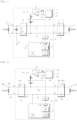
Fig. 1 ] lafigure 1 représente un compteur électrique selon un premier mode de réalisation de l'invention, le compteur étant un compteur monophasé ; - [
Fig. 2 ] lafigure 2 représente un compteur électrique selon un deuxième mode de réalisation de l'invention, le compteur étant un compteur triphasé.
- [
Fig. 1 ] therefigure 1 represents an electric meter according to a first embodiment of the invention, the meter being a single-phase meter; - [
Fig. 2 ] therefigure 2 represents an electric meter according to a second embodiment of the invention, the meter being a three-phase meter.
En référence à la
Le réseau de distribution 3 comprend une phase 4 et un neutre 5.Distribution network 3 includes a phase 4 and a neutral 5.
Un disjoncteur 6 est situé à l'extérieur et en aval du compteur 1. Ici, lorsque l'on parle de la position relative des différents éléments par rapport à l'installation 2 et au réseau 3, on entend :
- par « en amont » : du côté du réseau 3 ;
- par « en aval » : du côté de l'installation 2.
- by “upstream”: on the side of network 3;
- by “downstream”: on the side of
installation 2.
Le disjoncteur 6 est positionné entre le compteur 1 et l'installation 2.
Le compteur 1 comprend un port de phase amont P relié à la phase 4 et un port de neutre amont N relié au neutre 5. Le compteur 1 comporte de plus un port de phase aval P' et un port de neutre aval N'.
Le port de phase aval P' et le port de neutre aval N' du compteur 1 sont reliés à l'installation 2 respectivement via un interrupteur 8 et un interrupteur 9 intégrés dans le disjoncteur 6.The downstream phase port P' and the downstream neutral port N' of
Le compteur 1 comporte de plus un conducteur de phase 10, qui est relié à la phase 4 du réseau de distribution 3 via le port de phase amont P, et qui est relié au disjoncteur 6 via le port de phase aval P'. Le compteur 1 comporte de plus un conducteur de neutre 11, qui est relié au neutre 5 via le port de neutre amont N, et qui est relié au disjoncteur 6 via le port de neutre aval N'.The
Le compteur 1 comprend de plus un organe de coupure 12 comprenant un interrupteur 13 monté sur le conducteur de phase 10.The
Le compteur 1 comprend une masse électrique 14. Le conducteur de phase 10 est relié à la masse 14 à proximité du port de phase amont P et en amont de l'organe de coupure 12. Cette mise à la masse du conducteur de phase 10 s'explique par le fait que le compteur 1 comporte un capteur de courant, permettant de mesurer le courant de phase circulant sur la phase 4, qui est un shunt (non représenté ici), positionné sur le conducteur de phase 10 en amont de l'organe de coupure 12. Sans mise à la masse du conducteur de phase 10, la tension aux bornes du shunt serait de l'ordre de celle présente entre la phase et le neutre du réseau 3, et donc très élevée. La mise à la masse du conducteur de phase 10 permet d'obtenir une tension faible aux bornes du shunt (ici de l'ordre de 3,3V maximum après l'application d'un gain sachant que la tension aux bornes d'un shunt est de l'ordre de 15 à 20mV pour un courant le traversant de 100A efficace), qui correspond à la plage de tension acceptable en entrée du microcontrôleur de métrologie (non représenté ici) intégré dans le compteur 1.The
Le compteur 1 comporte de plus un circuit de détection.
Le circuit de détection comprend une chaîne d'injection 15, une chaîne de mesure 16, et un composant de traitement.The detection circuit includes an
Ici, par « chaîne », on entend une succession d'un ou de plusieurs composants (ou modules fonctionnels) connectés en série.Here, by “chain”, we mean a succession of one or more components (or functional modules) connected in series.
La chaîne d'injection 15 comprend au moins un composant générateur (en l'occurrence ici deux composants générateurs), une résistance R, et un composant d'injection (en l'occurrence ici un premier condensateur C1).The
Les deux composants générateurs comprennent un module générateur 20, intégré dans le microcontrôleur applicatif 17 du compteur 1, et un driver 21.The two generator components include a
Le microcontrôleur 17 comprend une sortie PWM 22 (pour Pulse Width Modulation). La sortie du module générateur 20 est reliée à la sortie PWM 22.The
Le driver 21 est ici un amplificateur monté en suiveur. La sortie 22 du microcontrôleur 17 est reliée à l'entrée non inverseuse du driver 21. L'entrée inverseuse du driver 21 est reliée à la sortie du driver 21.
La sortie du driver 21 est reliée à une première borne de la résistance R, dont une deuxième borne est reliée à une première borne du premier condensateur C1. La deuxième borne du premier condensateur C1 est connectée au conducteur de phase 10 en aval de l'organe de coupure 12.The output of
La résistance R a une valeur de résistance qui est ici égale à 1kΩ.The resistor R has a resistance value which is here equal to 1kΩ.
Le premier condensateur C1 a une valeur de capacité qui est ici égale à 47nF. Le premier condensateur C1 est intégré dans un premier filtre passe-haut (filtre R-C1) permettant de filtrer des signaux parasites provenant du réseau de distribution 3.The first capacitor C1 has a capacitance value which is here equal to 47nF. The first capacitor C1 is integrated into a first high-pass filter (filter R-C1) making it possible to filter spurious signals coming from the distribution network 3.
La chaîne de mesure 16 comprend les éléments suivants, disposés successivement d'amont en aval : un deuxième filtre passe-haut 24, un convertisseur analogique-numérique (CAN) 25, un détecteur d'enveloppe 26 et un filtre passe-bas 27.The
Ici, lorsque l'on parle de la position relative des différents éléments dans la chaîne de mesure 16, on entend :
- par « en amont » : du côté de la grandeur mesurée ;
- par « en aval » : du côté du traitement de la mesure.
- by “upstream”: on the side of the measured quantity;
- by “downstream”: on the processing side of the measurement.
Le deuxième filtre passe-haut 24 est donc ici un filtre analogique alors que le détecteur d'enveloppe 26 et le filtre passe-bas 27 sont des modules numériques.The second high-
Le CAN 25, le détecteur d'enveloppe 26 et le filtre passe-bas 27 sont ici intégrés dans le microcontrôleur 17.The
Le composant de traitement du circuit de détection est ici le microcontrôleur 17.The processing component of the detection circuit is here the
Le microcontrôleur 17 est adapté à exécuter des instructions d'un programme pour mettre en oeuvre le procédé de détection qui va être décrit. Le programme est stocké dans une mémoire 28, qui est intégrée dans ou reliée au microcontrôleur 17.The
Le compteur 1 comprend en outre un deuxième condensateur C2 positionné en amont de l'organe de coupure 12 et ayant une première borne connectée au conducteur de neutre 11 et une deuxième borne connectée au conducteur de phase 10. Le deuxième condensateur C2 a une valeur de capacité typiquement égale à celle du premier condensateur C1, c'est-à-dire ici à 47nF. Le deuxième condensateur C2, ainsi positionné entre le conducteur de neutre 11 et le conducteur de phase 10, permet de constituer un chemin de retour de masse maîtrisé pour les mesures réalisées pendant la détection (on rappelle que l'organe de coupure 12 est ouvert lors de la détection).The
On décrit maintenant en détail la manière dont l'invention fonctionne.We now describe in detail how the invention works.
Lorsque l'organe de coupure 12 est ouvert, un signal de test St est injecté périodiquement et pendant une durée prédéterminée par la chaîne d'injection 15. La période est par exemple égale à 1s et la durée prédéterminée à 500ms, c'est-à-dire que, lorsque l'organe de coupure 12 est ouvert, le signal de test St est injecté pendant 500ms et ce, toutes les 1s.When the
Alternativement, la chaîne d'injection 15 pourrait, lorsque l'organe de coupure 12 est ouvert, injecter le signal de test St en continu.Alternatively, the
Pour réaliser cette injection, le module générateur 20 du microcontrôleur 17 produit le signal de test St et l'applique sur la sortie 22.To carry out this injection, the
Le signal de test St est ici un signal alternatif carré (ou rectangulaire) ayant une fréquence avantageusement au moins cent fois supérieure à la fréquence du courant de phase circulant sur la phase 4 du réseau de distribution 3.The test signal St is here a square (or rectangular) alternating signal having a frequency advantageously at least one hundred times higher than the frequency of the phase current circulating on phase 4 of the distribution network 3.
Ici, la fréquence du courant de phase est égale à 50Hz, et la fréquence du signal de test St est égale à 10kHz.Here, the frequency of the phase current is equal to 50Hz, and the frequency of the test signal St is equal to 10kHz.
Le signal de test St est généré par le microcontrôleur 17 avec un niveau de tension prédéterminé, ici égal à 3,3V (crête à crête).The test signal St is generated by the
Le signal de test St est appliqué sur l'entrée non inverseuse du driver 21 et est donc reproduit sur la sortie du driver 21.The test signal St is applied to the non-inverting input of
Le driver 21 forme une source de courant fournissant un courant complémentaire permettant d'assurer que le signal de test St est généré avec un niveau de courant suffisant pour conserver, en sortie des composants générateurs (c'est-à-dire ici en sortie du driver 21), un niveau de tension égal au niveau de tension prédéterminé. Le driver 21 est ici nécessaire, car les différents éléments constituant et reliés à la chaîne d'injection 15 « tirent » du courant que n'est pas capable de fournir seul le microcontrôleur 17.The
La résistance R permet de limiter le courant.The resistance R limits the current.
Le premier condensateur C1 permet d'injecter le signal de test St, produit par le microcontrôleur 17 et le driver 21, sur le conducteur de phase 10 en aval de l'organe de coupure 12.The first capacitor C1 makes it possible to inject the test signal St, produced by the
La chaîne de mesure 16 permet de mesurer, en un point de mesure Pm de la chaîne d'injection 15 situé entre le au moins un composant générateur et le composant d'injection, un niveau de tension intermédiaire du signal de test St.The measuring
Le point de mesure Pm est ici situé entre la résistance R et le premier condensateur C1.The measuring point Pm is here located between the resistor R and the first capacitor C1.
Le deuxième filtre passe-haut 24 est ici un filtre passe-haut actif de gain égal à 1. La fréquence de coupure du deuxième filtre passe-haut 24 est typiquement égale à 5kHz. Le deuxième filtre passe-haut 24, situé en amont du CAN 25, permet d'éliminer le 50Hz éventuel (qui peut être capté par effet d'antenne dans le cas où l'organe de coupure 12 et le disjoncteur 6 sont tous les 2 ouverts) et les éventuelles perturbations venant du réseau 3. Le deuxième filtre passe-haut 24 permet donc de présenter au CAN 25 un signal non perturbé. Il suffit alors de détecter l'enveloppe de ce signal (via le détecteur d'enveloppe numérique 26) et de filtrer en numérique la sortie du détecteur 26 par le filtre passe-bas 27, dont la fréquence de coupure est typiquement égale à 10Hz.The second high-
Le microcontrôleur 17 compare le niveau de tension intermédiaire mesuré du signal de test St avec un seuil prédéterminé, et détecte que le disjoncteur 6 est ouvert lorsque le niveau de tension intermédiaire du signal de test St est supérieur au seuil prédéterminé, et que le disjoncteur 6 est fermé lorsque le niveau de tension intermédiaire du signal de test St est inférieur ou égal au seuil prédéterminé.The
En effet, lorsque le disjoncteur 6 est ouvert, le signal entrant vers le CAN 25 est élevé.Indeed, when
On suppose ici que le module de la charge Z(abonné) et la charge Z(amont) sont très faibles devant la résistance R à 10kHz (mais cela n'est pas systématique, du moins en ce qui concerne Z(abonné) : voir plus bas).We assume here that the module of the load Z(subscriber) and the load Z(upstream) are very low compared to the resistance R at 10kHz (but this is not systematic, at least with regard to Z(subscriber): see lower).
Après filtrage passe-bas, le niveau de tension intermédiaire mesuré est égal à un niveau haut Vh égal à 3,3V (c'est-à-dire au niveau de tension prédéterminé Vp du signal de test St).After low-pass filtering, the measured intermediate voltage level is equal to a high level Vh equal to 3.3V (that is to say at the predetermined voltage level Vp of the test signal St).
Par contre, lorsque le disjoncteur 6 est fermé, le signal entrant vers le CAN 25 est sensiblement plus faible. Après filtrage passe-bas, le niveau de tension intermédiaire mesuré est égal à un niveau bas Vb, qui est égal à (division de tension) : ![]()
Z(C1) est une impédance du premier condensateur, Z(C2) est une impédance du deuxième condensateur, Z(amont) est une impédance entre la phase et le neutre en amont du compteur 1, Z(abonné) est une impédance entre la phase et le neutre en aval du compteur 1, lesdites impédances étant estimées à une fréquence du signal de test (c'est-à-dire à 10kHz).On the other hand, when ![]()
Z(C1) is an impedance of the first capacitor, Z(C2) is an impedance of the second capacitor, Z(upstream) is an impedance between the phase and the neutral upstream of
Le seuil prédéterminé Sp est donc compris entre le niveau haut Vh (égal ici au niveau de tension prédéterminé Vp) et le niveau bas Vb.The predetermined threshold Sp is therefore between the high level Vh (here equal to the predetermined voltage level Vp) and the low level Vb.
Le niveau bas est ici égal à 1,06V.The low level here is equal to 1.06V.
Le seuil prédéterminé Sp « idéal », et utilisé ici, est donc tel que : ![]()
![]()
On note que, par défaut, la sortie PWM 22 est à 0, de sorte qu'aucune injection du signal de test St n'est appliquée au niveau du point de mesure. C'est également toujours le cas lorsque l'organe de coupure 12 est fermé.Note that, by default, the
En référence à la
Le réseau de distribution 103 comprend trois phases 104_i (i variant de 1 à 3) et un neutre 105.The
Pour chaque phase 104_i, le compteur 101 comprend un port de phase amont Pi relié à ladite phase 104_i, et un port de phase aval P'i.For each phase 104_i, the
Le compteur 101 comprend de plus un port de neutre amont N relié au neutre 105 et un port de neutre aval N'.The
Les ports de phase aval P'i et le port de neutre aval N' du compteur 101 sont reliés à l'installation 102, respectivement via des interrupteurs 108_i et un interrupteur 109 intégrés dans le disjoncteur 106.The downstream phase ports P'i and the downstream neutral port N' of the
Le compteur 101 comporte de plus, pour chaque phase 104_i, un conducteur de phase 110_i relié à ladite phase 104_i via le port de phase amont Pi associé. Le compteur 101 comporte de plus un conducteur de neutre 111 relié au neutre 105 via le port de neutre amont N.The
Le compteur 101 comprend de plus un organe de coupure 112 comprenant, pour chaque phase, un interrupteur 113_i monté sur le conducteur de phase 110_i associé.The
Le compteur 101 comprend de plus un circuit de détection permettant de détecter, lorsque l'organe de coupure 112 est ouvert, si le disjoncteur 106 est ouvert ou fermé.The
On sait que les quatre interrupteurs 108_i, 109 du disjoncteurs 106, tout comme les trois interrupteurs 113_i de l'organe de coupure 112, sont soit tous ouverts en même temps, soit tous fermés en même temps.We know that the four switches 108_i, 109 of the
Par conséquent, le compteur 101 n'intègre ici qu'un seul circuit de détection, connecté à un seul conducteur de phase 110_i (reliée à la phase 104_i représentée sur la
Le circuit de détection du compteur 101 fonctionne de la même manière que le circuit de détection du compteur 1.The
Le circuit de détection comporte une chaîne d'injection 115 qui comprend le module générateur 120 intégré dans le microcontrôleur applicatif 117 et le driver 121 (les deux composants générateurs), un premier condensateur C1 (le composant d'injection), et une résistance R montée entre la sortie du driver 121 et le premier condensateur C1. Le premier condensateur C1 et la résistance R forment un premier filtre passe-haut.The detection circuit comprises an
Le circuit de détection comprend aussi une chaîne de mesure 116 comprenant un deuxième filtre passe-haut 124 (analogique), un CAN 125, un détecteur d'enveloppe 126 (numérique) et un filtre passe-bas 127 (numérique).The detection circuit also includes a
Le circuit de détection comprend de plus un composant de traitement, en l'occurrence le microcontrôleur 117 (dans lequel sont intégrés le CAN 125, le détecteur d'enveloppe 126 et le filtre passe-bas 127).The detection circuit further comprises a processing component, in this case the microcontroller 117 (in which the
On note que, dans le cas du compteur triphasé 101, pour chaque phase 104_i, le capteur de courant utilisé pour mesurer le courant de phase circulant sur ladite phase 104_i est un tore et non un shunt. Le conducteur de neutre 105 peut donc être mis à la masse (masse électrique 114) qui est visible par le microcontrôleur 117, de sorte que le deuxième condensateur C2 n'est pas nécessaire.Note that, in the case of the three-
Lorsque l'organe de coupure 112 est ouvert, le signal de test St est généré et injecté de la même manière que pour le circuit de détection précédemment décrit.When the
On suppose à nouveau que le module de la charge Z(abonné) est très faible devant la résistance R à 10kHz.We assume again that the modulus of the load Z (subscriber) is very low compared to the resistance R at 10kHz.
Lorsque le disjoncteur 106 est ouvert, le niveau de tension intermédiaire mesuré est égal à un niveau haut Vh égal à 3,3V (c'est-à-dire au niveau de tension prédéterminé Vp du signal de test St).When the
Lorsque le disjoncteur 106 est fermé, le niveau de tension intermédiaire mesuré est sensiblement plus faible. Après filtrage passe-bas, le niveau de tension intermédiaire mesuré est égal à un niveau bas Vb, qui est égal à : ![]()
Z(C1) est une impédance du premier condensateur, Z(abonné) est une impédance entre la phase et le neutre en aval du compteur, lesdites impédances étant estimées à une fréquence du signal de test (ici 10kHz).When the ![]()
Z(C1) is an impedance of the first capacitor, Z(subscriber) is an impedance between the phase and the neutral downstream of the counter, said impedances being estimated at a frequency of the test signal (here 10kHz).
Le seuil prédéterminé Sp est donc compris entre le niveau haut Vh et le niveau bas Vb.The predetermined threshold Sp is therefore between the high level Vh and the low level Vb.
Le niveau bas Vb est ici égal à 1,06V.The low level Vb here is equal to 1.06V.
Le seuil prédéterminé Sp « idéal », et utilisé ici, est donc tel que : ![]()
![]()
On note ici que, aussi bien dans le cas du compteur monophasé 1 que du compteur triphasé 101, on a considéré que le module de la charge Z(abonné) est très faible devant la résistance R (à 10kHz).We note here that, both in the case of the single-
Or, cette configuration « standard » n'est pas systématique.However, this “standard” configuration is not systematic.
L'impédance Z(abonné) peut ne pas être négligeable devant la résistance R, voire même être sensiblement supérieure à R (l'impédance Z(amont), quant à elle, étant inférieure ou égale à 2Ω, reste systématiquement négligeable devant R).The impedance Z(subscriber) may not be negligible compared to the resistance R, or even be significantly greater than R (the impedance Z(upstream), for its part, being less than or equal to 2Ω, remains systematically negligible compared to R) .
Cela se produit par exemple en Espagne, où le pire cas correspond au cas où le disjoncteur 6 (respectivement 106) est éloigné géographiquement du compteur 1 (respectivement 101) .This happens for example in Spain, where the worst case corresponds to the case where circuit breaker 6 (respectively 106) is geographically distant from meter 1 (respectively 101).
Dans ce cas, lorsque le disjoncteur est ouvert, le câble entre le compteur et le disjoncteur ramène aux bornes du compteur une impédance équivalente, qui dépend de la longueur et de la nature du câble, et qui peut aller jusqu'à 1200kΩ.In this case, when the circuit breaker is open, the cable between the meter and the circuit breaker brings to the terminals of the meter an equivalent impedance, which depends on the length and nature of the cable, and which can go up to 1200kΩ.
Lorsque le disjoncteur est fermé, en plus de ces 1200kΩ, on a en parallèle une impédance Z(abonné) pouvant atteindre 210kΩ.When the circuit breaker is closed, in addition to these 1200kΩ, we have in parallel an impedance Z (subscriber) which can reach 210kΩ.
Dans cette configuration « de type Espagne », afin d'améliorer la différence entre le niveau de tension intermédiaire mesuré au point Pm lorsque le disjoncteur est ouvert (niveau haut Vh) et lorsque le disjoncteur est fermé (niveau bas Vb), on modifie la valeur de R et de C1 (C2 reste inchangée à 47nF).In this “Spain type” configuration, in order to improve the difference between the voltage level intermediate measured at point Pm when the circuit breaker is open (high level Vh) and when the circuit breaker is closed (low level Vb), the value of R and C1 is modified (C2 remains unchanged at 47nF).
On choisit par exemple R = 22kΩ et C1 = 2,2nF.For example, we choose R = 22kΩ and C1 = 2.2nF.
Ainsi, dans cette configuration « de type Espagne », on obtient les niveaux de tension intermédiaires suivants, que l'on soit en monophasé ou en triphasé (en utilisant les formules précédentes) :
- disjoncteur ouvert : Vh = 3,24V ;
- disjoncteur fermé : Vb = 2,94V,
ce qui donne un seuil prédéterminé Sp « idéal » :
- circuit breaker open: Vh = 3.24V;
- circuit breaker closed: Vb = 2.94V,
which gives a predetermined “ideal” threshold Sp:
Par ailleurs, ces « nouvelles » valeurs de R et de C1 sont tout à fait applicables à la configuration « standard » décrite précédemment (pas d'impédance ramenée de 1200kΩ et Z(abonné) << R).Furthermore, these “new” values of R and C1 are entirely applicable to the “standard” configuration described previously (no impedance reduced to 1200kΩ and Z(subscriber) << R).
Dans la configuration « standard », les calculs avec les nouvelles valeurs de composants donnent :
- disjoncteur ouvert : Vh = 3,3V ;
- disjoncteur fermé : Vb = 1,03V.
- circuit breaker open: Vh = 3.3V;
- circuit breaker closed: Vb = 1.03V.
Le seuil prédéterminé Sp « idéal » est donc tel que : ![]()
![]()
On note en outre qu'un seuil prédéterminé Sp égal à 3,09V, au lieu de 2,17V, est compatible à la fois avec la configuration « de type Espagne » et avec la configuration « standard ».We further note that a predetermined threshold Sp equal to 3.09V, instead of 2.17V, is compatible with both the “Spain type” configuration and the “standard” configuration.
On note aussi que la fréquence de coupure à 3dB du filtre Passe-Haut R-C1 reste quasiment inchangée à 3% près, en utilisant les valeurs utilisées pour la configuration « standard » ou la configuration « de type Espagne », puisqu'elle passe de 3386Hz à 3288Hz.We also note that the 3dB cutoff frequency of the R-C1 High Pass filter remains almost unchanged within 3%, using the values used for the "standard" configuration or the "Spain type" configuration, since it passes from 3386Hz to 3288Hz.
Bien entendu, l'invention n'est pas limitée aux modes de réalisation décrits mais englobe toute variante entrant dans le champ de l'invention telle que définie par les revendications.Of course, the invention is not limited to the embodiments described but encompasses any variant falling within the scope of the invention as defined by the claims.
Le détecteur d'enveloppe, qui est ici réalisé en numérique, pourrait tout aussi bien être réalisé en analogique, et donc positionné en amont du CAN.The envelope detector, which is here made digital, could just as easily be made analog, and therefore positioned upstream of the ADC.
Les valeurs de capacité du premier condensateur C1 et du deuxième condensateur C2 pourraient être différentes de celles données ici. De même, la valeur de la résistance R pourrait être modifiée en l'augmentant typiquement.The capacitance values of the first capacitor C1 and the second capacitor C2 could be different from those given here. Likewise, the value of the resistance R could be modified by typically increasing it.
La fréquence du signal de test pourrait être également modifiée, auquel cas il faudrait adapter le seuil de détection prédéterminé à schéma équivalent. Le seuil de détection prédéterminé pourrait être paramétrable.The frequency of the test signal could also be modified, in which case it would be necessary to adapt the predetermined detection threshold to an equivalent scheme. The predetermined detection threshold could be configurable.
Le driver n'est pas obligatoire. En particulier, si le module générateur qui génère le signal de test (ici le microcontrôleur applicatif) est capable de fournir suffisamment de courant, le driver n'est pas nécessaire.The driver is not required. In particular, if the generator module which generates the test signal (here the application microcontroller) is capable of supplying sufficient current, the driver is not necessary.
Le microcontrôleur dans lequel est mise en oeuvre l'invention n'est pas nécessairement le microcontrôleur applicatif mais pourrait être un composant distinct.The microcontroller in which the invention is implemented is not necessarily the application microcontroller but could be a separate component.
Le composant de traitement dans lequel est mise en oeuvre l'invention n'est pas nécessairement un microcontrôleur, mais pourrait être un composant différent, et par exemple un processeur classique, un DSP (pour Digital Signal Processor, que l'on peut traduire par « processeur de signal numérique »), ou bien un circuit logique programmable tel qu'un FPGA (pour Field Programmable Gate Arrays) ou un ASIC (pour Application Spécifie Integrated Circuit). The processing component in which the invention is implemented is not necessarily a microcontroller, but could be a different component, and for example a classic processor, a DSP (for Digital Signal Processor, which can be translated as “digital signal processor”), or a programmable logic circuit such as an FPGA (for Field Programmable Gate Arrays ) or an ASIC (for Application Specified Integrated Circuit).
Claims (17)
- A meter (1; 101) arranged to measure electrical energy delivered to an installation (2; 102) by a distribution network (3; 103) comprising a phase line and a neutral line, the meter being arranged to be connected to a circuit breaker (6; 106) situated outside the meter and downstream therefrom, the meter comprising:· a phase conductor (10; 110_i) and a neutral conductor (11; 111) arranged to be connected respectively to the phase line and to the neutral line of the distribution network;· a cut-off member (12; 112) connected in the phase conductor;· a detection circuit comprising:∘ an injection chain (15; 115) comprising at least one generator component and an injection component, the at least one generator component being arranged, while the cut-off member is open, to generate a test signal (St) with a predetermined voltage level, the injection component being arranged to inject the test signal into the phase conductor downstream from the cut-off member;∘ a measurement chain (16; 116) arranged to measure an intermediate voltage level of the test signal at a measurement point (Pm) of the injection chain, which point is situated between the at least one generator component and the injection component;∘ a processor component (17; 117) arranged to act as a function of the intermediate voltage level in order to determine whether the circuit breaker is open or closed.
- A meter according to claim 1, the injection component being a first capacitor (C1) that is integrated in a first highpass filter serving to filter out interfering signals coming from the distribution network.
- A meter according to either preceding claim, wherein the at least one generator component comprises both a generator module (20; 120) arranged to produce the test signal with the predetermined voltage level and also a driver (21; 121) forming a current source arranged to ensure that the test signal is generated with a current level that is sufficient for conserving a voltage level at the output of the at least one generator component that is equal to the predetermined voltage level.
- A meter according to any preceding claim, wherein the measurement chain comprises in succession, from upstream to downstream, a second highpass filter (24; 124), an envelope detector (26; 126), and a lowpass filter (27; 127) .
- A meter according to claim 4, further comprising an analog-to-digital converter (25; 125) positioned upstream from the envelope detector.
- A meter according to claim 4, further comprising an analog-to-digital converter positioned downstream from the envelope detector.
- A meter according to any preceding claim, the injection chain being arranged, while the cut-off member is open, to inject the test signal periodically for a predetermined duration.
- A meter according to any one of claims 1 to 6, the injection chain being arranged, while the cut-off member is open, to inject the test signal continuously.
- A meter according to any preceding claim, wherein the test signal is an alternating signal at a frequency that is at least one hundred times greater than the frequency of the phase current flowing in the phase line of the distribution network.
- A meter according to any preceding claim, the meter being a single-phase meter (1).
- A meter according to claim 10, wherein the phase conductor is connected to electrical ground (14) of the meter upstream from the cut-off member, the meter further comprising a second capacitor (C2) positioned upstream from the cut-off member and having a first terminal connected to the neutral conductor and a second terminal connected to the phase conductor.
- A meter according to claim 11, the injection component being a first capacitor (C1), the injection chain comprising a resistor (R) connected between the first capacitor and an output of the at least one generator component, the processor component being arranged to compare the intermediate voltage level of the test signal with a predetermined detection threshold, and to detect that the circuit breaker is open when the intermediate voltage level of the test signal is greater than the predetermined threshold and that the circuit breaker is closed when the intermediate voltage level of the test signal is less than or equal to the predetermined detection threshold, the predetermined detection threshold lying between a high level and a low level Vb such that:

Vp is the predetermined voltage level, Z(C1) is the impedance of the first capacitor, Z(C2) is the impedance of the second capacitor, Z(upstream) is the impedance between the phase line and the neutral line upstream from the meter, and Z(subscriber) is the impedance between the phase line and the neutral line downstream from the meter, said impedances being estimated at the frequency of the test signal. - A meter according to any one of claims 1 to 9, the meter being a three-phase meter (101).
- A meter according to claim 13, the injection component being a first capacitor (C1), the injection chain including a resistor (R) connected between the first capacitor and an output of the at least one generator component, the processor component being arranged to compare the intermediate voltage level of the test signal with a predetermined detection threshold, and to detect that the circuit breaker is open when the intermediate voltage level of the test signal is greater than the predetermined threshold and that the circuit breaker is closed when the intermediate voltage level of the test signal is less than or equal to the predetermined detection threshold, the predetermined detection threshold lying between a high level and a low level Vb such that:
 Vp is the predetermined voltage level of the test signal,Z(C1) is the impedance of the first capacitor, andZ(subscriber) is the impedance between the phase line and the neutral line downstream from the meter, said impedances being estimated at the frequency of the test signal.
 - A detection method performed in the processor component (17; 117) of a meter according to any preceding claim, the method comprising the following steps performed while the cut-off member is open:· using the injection chain to generate and inject the test signal into the phase conductor downstream from the cut-off member;· acquiring the intermediate voltage level of the test signal;· as a function of the intermediate voltage level of the test signal, determining whether the circuit breaker is open or closed.
- A computer program including instructions that cause the processor component of the meter according to any one of claims 1 to 14 to execute the steps of the detection method according to claim 15.
- A computer-readable storage medium storing the computer program according to claim 16.
Applications Claiming Priority (1)
| Application Number | Priority Date | Filing Date | Title |
|---|---|---|---|
| FR2112312A FR3129488A1 (en) | 2021-11-22 | 2021-11-22 | Detection of the open or closed state of a circuit breaker |
Publications (2)
| Publication Number | Publication Date |
|---|---|
| EP4184183A1 EP4184183A1 (en) | 2023-05-24 |
| EP4184183B1 true EP4184183B1 (en) | 2024-03-27 |
Family
ID=79601784
Family Applications (1)
| Application Number | Title | Priority Date | Filing Date |
|---|---|---|---|
| EP22207560.8A Active EP4184183B1 (en) | 2021-11-22 | 2022-11-15 | Detection of open or closed state of a circuit breaker |
Country Status (4)
| Country | Link |
|---|---|
| US (1) | US20230160961A1 (en) |
| EP (1) | EP4184183B1 (en) |
| CN (1) | CN116148648A (en) |
| FR (1) | FR3129488A1 (en) |
Family Cites Families (2)
| Publication number | Priority date | Publication date | Assignee | Title |
|---|---|---|---|---|
| FR2931947B1 (en) * | 2008-05-29 | 2010-08-13 | Electricite De France | CLOSURE ORGAN HF CUT. |
| FR3094498B1 (en) * | 2019-03-25 | 2021-04-02 | Sagemcom Energy & Telecom Sas | Electricity meter comprising a circuit for detecting an open or closed state of a circuit breaker |
-
2021
- 2021-11-22 FR FR2112312A patent/FR3129488A1/en active Pending
-
2022
- 2022-11-15 EP EP22207560.8A patent/EP4184183B1/en active Active
- 2022-11-21 US US17/991,607 patent/US20230160961A1/en active Pending
- 2022-11-22 CN CN202211465069.2A patent/CN116148648A/en active Pending
Also Published As
| Publication number | Publication date |
|---|---|
| EP4184183A1 (en) | 2023-05-24 |
| FR3129488A1 (en) | 2023-05-26 |
| CN116148648A (en) | 2023-05-23 |
| US20230160961A1 (en) | 2023-05-25 |
Similar Documents
| Publication | Publication Date | Title |
|---|---|---|
| CA2546891C (en) | Equilibrated charging method for a lithium-ion or lithium-polymer battery | |
| CA2594826C (en) | Method for the balanced charging of a lithium-ion or lithium-polymer battery | |
| FR3019303B1 (en) | DEVICE FOR MEASURING AT LEAST ONE PHYSICAL SIZE OF AN ELECTRICAL INSTALLATION | |
| EP2904410B1 (en) | Electric power meter | |
| EP3715874B1 (en) | Electricity meter comprising a circuit for detecting an open or closed state of a circuit breaker | |
| EP4134695B1 (en) | Verification of the metrological precision of an electricity meter | |
| FR2978556A1 (en) | EARTH CONDUCTOR MONITORING DEVICE WITH IMPEDANCE MEASUREMENT | |
| FR3073660A1 (en) | ELECTRICAL CONNECTION COMPRISING AN ELECTRICAL PROTECTION DEVICE. | |
| EP3009851B1 (en) | Counter for detecting fraud by bypass | |
| EP4184183B1 (en) | Detection of open or closed state of a circuit breaker | |
| EP0592337B1 (en) | Electronic trip device comprising earth protection | |
| EP3660524B1 (en) | Method for determining a corrected characteristic current-voltage curve of an electrical system | |
| FR3066277A1 (en) | DEVICE AND METHOD FOR DETECTING AN ELECTRICAL CHARGE | |
| EP4105670B1 (en) | Detection of the opening of an external transformer | |
| EP3961239B1 (en) | Verification of the precision of the measurements taken by an electricity meter | |
| EP1357386B1 (en) | Device and method for electrical charge detection and electrical apparatus equipped with such a device | |
| EP4155738B1 (en) | Detecting defective clamping | |
| EP3771055B1 (en) | Device for detecting overcurrent in an electrical power circuit comprising a filtering means controlling the charge of a capacitor | |
| EP3033760A1 (en) | Method, device and computer program for controlling a mechatronic circuit breaker | |
| EP3015873B1 (en) | Method for detecting a fraudulent attempt to bypass a meter | |
| WO2021043749A1 (en) | Method for managing the operation of a battery |
Legal Events
| Date | Code | Title | Description |
|---|---|---|---|
| PUAI | Public reference made under article 153(3) epc to a published international application that has entered the european phase |
Free format text: ORIGINAL CODE: 0009012 |
|
| STAA | Information on the status of an ep patent application or granted ep patent |
Free format text: STATUS: EXAMINATION IS IN PROGRESS |
|
| 17P | Request for examination filed |
Effective date: 20221115 |
|
| AK | Designated contracting states |
Kind code of ref document: A1 Designated state(s): AL AT BE BG CH CY CZ DE DK EE ES FI FR GB GR HR HU IE IS IT LI LT LU LV MC ME MK MT NL NO PL PT RO RS SE SI SK SM TR |
|
| RIC1 | Information provided on ipc code assigned before grant |
Ipc: G01R 22/06 20060101AFI20230825BHEP |
|
| GRAP | Despatch of communication of intention to grant a patent |
Free format text: ORIGINAL CODE: EPIDOSNIGR1 |
|
| STAA | Information on the status of an ep patent application or granted ep patent |
Free format text: STATUS: GRANT OF PATENT IS INTENDED |
|
| INTG | Intention to grant announced |
Effective date: 20231013 |
|
| RBV | Designated contracting states (corrected) |
Designated state(s): AL AT BE BG CH CY CZ DE DK EE ES FI FR GB GR HR HU IE IS IT LI LT LU LV MC ME MK MT NL NO PL PT RO RS SE SI SK SM TR |
|
| RAP3 | Party data changed (applicant data changed or rights of an application transferred) |
Owner name: SAGEMCOM ENERGY & TELECOM SAS |
|
| GRAS | Grant fee paid |
Free format text: ORIGINAL CODE: EPIDOSNIGR3 |
|
| GRAA | (expected) grant |
Free format text: ORIGINAL CODE: 0009210 |
|
| STAA | Information on the status of an ep patent application or granted ep patent |
Free format text: STATUS: THE PATENT HAS BEEN GRANTED |
|
| AK | Designated contracting states |
Kind code of ref document: B1 Designated state(s): AL AT BE BG CH CY CZ DE DK EE ES FI FR GB GR HR HU IE IS IT LI LT LU LV MC ME MK MT NL NO PL PT RO RS SE SI SK SM TR |
|
| REG | Reference to a national code |
Ref country code: GB Ref legal event code: FG4D Free format text: NOT ENGLISH |
|
| REG | Reference to a national code |
Ref country code: CH Ref legal event code: EP |
|
| REG | Reference to a national code |
Ref country code: DE Ref legal event code: R096 Ref document number: 602022002571 Country of ref document: DE |
|
| REG | Reference to a national code |
Ref country code: IE Ref legal event code: FG4D Free format text: LANGUAGE OF EP DOCUMENT: FRENCH |
|
| PG25 | Lapsed in a contracting state [announced via postgrant information from national office to epo] |
Ref country code: LT Free format text: LAPSE BECAUSE OF FAILURE TO SUBMIT A TRANSLATION OF THE DESCRIPTION OR TO PAY THE FEE WITHIN THE PRESCRIBED TIME-LIMIT Effective date: 20240327 |
|
| REG | Reference to a national code |
Ref country code: LT Ref legal event code: MG9D |
|
| PG25 | Lapsed in a contracting state [announced via postgrant information from national office to epo] |
Ref country code: GR Free format text: LAPSE BECAUSE OF FAILURE TO SUBMIT A TRANSLATION OF THE DESCRIPTION OR TO PAY THE FEE WITHIN THE PRESCRIBED TIME-LIMIT Effective date: 20240628 |
|
| PG25 | Lapsed in a contracting state [announced via postgrant information from national office to epo] |
Ref country code: RS Free format text: LAPSE BECAUSE OF FAILURE TO SUBMIT A TRANSLATION OF THE DESCRIPTION OR TO PAY THE FEE WITHIN THE PRESCRIBED TIME-LIMIT Effective date: 20240627 Ref country code: HR Free format text: LAPSE BECAUSE OF FAILURE TO SUBMIT A TRANSLATION OF THE DESCRIPTION OR TO PAY THE FEE WITHIN THE PRESCRIBED TIME-LIMIT Effective date: 20240327 |
|
| PG25 | Lapsed in a contracting state [announced via postgrant information from national office to epo] |
Ref country code: RS Free format text: LAPSE BECAUSE OF FAILURE TO SUBMIT A TRANSLATION OF THE DESCRIPTION OR TO PAY THE FEE WITHIN THE PRESCRIBED TIME-LIMIT Effective date: 20240627 Ref country code: NO Free format text: LAPSE BECAUSE OF FAILURE TO SUBMIT A TRANSLATION OF THE DESCRIPTION OR TO PAY THE FEE WITHIN THE PRESCRIBED TIME-LIMIT Effective date: 20240627 Ref country code: LT Free format text: LAPSE BECAUSE OF FAILURE TO SUBMIT A TRANSLATION OF THE DESCRIPTION OR TO PAY THE FEE WITHIN THE PRESCRIBED TIME-LIMIT Effective date: 20240327 Ref country code: HR Free format text: LAPSE BECAUSE OF FAILURE TO SUBMIT A TRANSLATION OF THE DESCRIPTION OR TO PAY THE FEE WITHIN THE PRESCRIBED TIME-LIMIT Effective date: 20240327 Ref country code: GR Free format text: LAPSE BECAUSE OF FAILURE TO SUBMIT A TRANSLATION OF THE DESCRIPTION OR TO PAY THE FEE WITHIN THE PRESCRIBED TIME-LIMIT Effective date: 20240628 Ref country code: FI Free format text: LAPSE BECAUSE OF FAILURE TO SUBMIT A TRANSLATION OF THE DESCRIPTION OR TO PAY THE FEE WITHIN THE PRESCRIBED TIME-LIMIT Effective date: 20240327 Ref country code: BG Free format text: LAPSE BECAUSE OF FAILURE TO SUBMIT A TRANSLATION OF THE DESCRIPTION OR TO PAY THE FEE WITHIN THE PRESCRIBED TIME-LIMIT Effective date: 20240327 |
|
| REG | Reference to a national code |
Ref country code: NL Ref legal event code: MP Effective date: 20240327 |
|
| PG25 | Lapsed in a contracting state [announced via postgrant information from national office to epo] |
Ref country code: SE Free format text: LAPSE BECAUSE OF FAILURE TO SUBMIT A TRANSLATION OF THE DESCRIPTION OR TO PAY THE FEE WITHIN THE PRESCRIBED TIME-LIMIT Effective date: 20240327 Ref country code: LV Free format text: LAPSE BECAUSE OF FAILURE TO SUBMIT A TRANSLATION OF THE DESCRIPTION OR TO PAY THE FEE WITHIN THE PRESCRIBED TIME-LIMIT Effective date: 20240327 |
|
| PG25 | Lapsed in a contracting state [announced via postgrant information from national office to epo] |
Ref country code: NL Free format text: LAPSE BECAUSE OF FAILURE TO SUBMIT A TRANSLATION OF THE DESCRIPTION OR TO PAY THE FEE WITHIN THE PRESCRIBED TIME-LIMIT Effective date: 20240327 |
|
| REG | Reference to a national code |
Ref country code: AT Ref legal event code: MK05 Ref document number: 1670404 Country of ref document: AT Kind code of ref document: T Effective date: 20240327 |