EP4184156A1 - Method for manufacturing ion sensor, and electrode body for ion sensor - Google Patents
Method for manufacturing ion sensor, and electrode body for ion sensor Download PDFInfo
- Publication number
- EP4184156A1 EP4184156A1 EP21842112.1A EP21842112A EP4184156A1 EP 4184156 A1 EP4184156 A1 EP 4184156A1 EP 21842112 A EP21842112 A EP 21842112A EP 4184156 A1 EP4184156 A1 EP 4184156A1
- Authority
- EP
- European Patent Office
- Prior art keywords
- ion
- sensitive film
- electrode body
- placement surface
- electrode
- Prior art date
- Legal status (The legal status is an assumption and is not a legal conclusion. Google has not performed a legal analysis and makes no representation as to the accuracy of the status listed.)
- Pending
Links
Images


Classifications
-
- G—PHYSICS
- G01—MEASURING; TESTING
- G01N—INVESTIGATING OR ANALYSING MATERIALS BY DETERMINING THEIR CHEMICAL OR PHYSICAL PROPERTIES
- G01N27/00—Investigating or analysing materials by the use of electric, electrochemical, or magnetic means
- G01N27/26—Investigating or analysing materials by the use of electric, electrochemical, or magnetic means by investigating electrochemical variables; by using electrolysis or electrophoresis
- G01N27/28—Electrolytic cell components
- G01N27/30—Electrodes, e.g. test electrodes; Half-cells
- G01N27/333—Ion-selective electrodes or membranes
Definitions
- the present invention relates to a method for manufacturing an ion sensor and an electrode member for an ion sensor.
- An ion sensor is used together with a reference electrode to measure a concentration of an ionic electrolyte in a sample, and is used by being mounted on an analysis device such as a clinical analysis device, a water quality analysis device, a soil analysis device, or a food analysis device.
- a film As an ion-sensitive film formed on a sensitive surface of the ion sensor, a film is known in the related art, which is obtained by, with a hydrophobic organic polymer such as polyvinyl chloride serving as a base, appropriately adding a plasticizer such as dibutyl phthalate (DBP), dipropyl phthalate (DPP), or 2-nitrophenyl octyl ether (NPOE) to the base, and mixing the base with an ion-sensitive substance such as valinomycin or a macrocyclic polyether derivative.
- a plasticizer such as dibutyl phthalate (DBP), dipropyl phthalate (DPP), or 2-nitrophenyl octyl ether (NPOE)
- the ion-sensitive film is prepared by applying a solvent solution, in which the organic polymer serving as the base of the ion-sensitive film and the ion-sensitive substance are dissolved in a volatile solvent at a predetermined ratio, to the sensitive surface of the ion sensor by brush application, dipping, dropwise adding, or the like so as to form an application film of the solution first, and then causing evaporation of the solvent to proceed while applying a stress in a direction of the sensitive surface.
- a solvent solution in which the organic polymer serving as the base of the ion-sensitive film and the ion-sensitive substance are dissolved in a volatile solvent at a predetermined ratio
- the ion sensor generally (for example, PTL 1) includes an electrode body, an internal solution, an ion-sensitive film, and an internal electrode.
- the electrode body of a flow-type ion sensor includes a specimen flow path, and a through hole is provided in a part of a side surface of the specimen flow path. Then, the through hole is covered with the ion-sensitive film so as to form a response surface, and the ion-sensitive film and the electrode body are bonded to each other at a portion other than the response surface.
- a bonding operation of the ion-sensitive film and the electrode body is performed by dissolving the organic polymer that constitutes the ion-sensitive film and the electrode body once using a volatile solvent such as tetrahydrofuran (THF) at a bonding interface of the ion-sensitive film and the electrode body, and then evaporating the volatile solvent.
- a volatile solvent such as tetrahydrofuran (THF)
- An object of the invention is to provide a method for manufacturing an ion sensor and an electrode member for an ion sensor, in which a bonding strength between the electrode body and an ion-sensitive film is improved regardless of a material variation so as to reduce occurrence of a performance failure.
- the invention provides a method for manufacturing an ion sensor in which an ion-sensitive film is bonded to an electrode member accommodating an internal solution and including an internal electrode.
- the method for manufacturing an ion sensor includes: an application step of applying water to a placement surface of an electrode body, in the electrode member, on which the ion-sensitive film is to be placed; a placement step of placing the ion-sensitive film in a state in which water is present on the placement surface; a pressurization step of pressurizing the ion-sensitive film from a side opposite to the electrode body; and an irradiation step of irradiating the ion-sensitive film with a laser beam from the side opposite to the electrode body in a state in which the ion-sensitive film is pressed against the electrode body.
- An electrode member for an ion sensor includes an internal electrode configured to output potential generated in an ion-sensitive film, and an electrode body accommodating an internal solution configured to electrically conduct the internal electrode and the ion-sensitive film.
- the electrode body includes a flow path through which a liquid containing a specimen to be measured flows, and a placement surface on which the ion-sensitive film is to be placed. A through portion that is exposed to the placement surface and brings the specimen into contact with the ion-sensitive film is formed at a predetermined position on an upper surface of the flow path.
- the ion-sensitive film and the placement surface are bonded to each other by pressurization and laser beam irradiation from above the ion-sensitive film in a state in which water is present in the placement surface other than the through portion.
- the invention it is possible to provide a method for manufacturing an ion sensor and an electrode member for an ion sensor in which a bonding strength between the electrode body and an ion-sensitive film is improved regardless of a material variation so as to reduce occurrence of a performance failure.
- FIG. 1 is an overall view showing an outline of a method for manufacturing an ion sensor 1 according to the present embodiment.
- water 2 a laser irradiator 3, and a weight 4 are used.
- an electrode body 5 although a wall surface on a front side, which facilitates understanding of the present embodiment, is not shown, the wall surface similar to a wall surface on a back side is actually provided.
- the electrode member for an ion sensor includes an internal electrode 14 that outputs potential generated in an ion-sensitive film, an electrode body 5 accommodating an internal solution (not shown) that electrically conducts the internal electrode 14 and the ion-sensitive film 10, an electrode body pin 15 that seals the internal solution so as not to leak the internal solution, and an electrode body plate 13 that serves as a bottom surface accommodating an internal container.
- the electrode body 5 includes a specimen flow path 7 which is formed inside the electrode body 5 and through which a liquid containing a specimen to be measured flows, and a placement surface 9 (bonding surface) on which the ion-sensitive film 10 is to be placed.
- the electrode body 5 has a rectangular parallelepiped shape having an outer dimension of about 11 mm ⁇ 20 mm ⁇ 24 mm, the specimen flow path 7 has a diameter of about 1 mm, and the placement surface 9 has a size of about 5 mm ⁇ 5 mm.
- a part of the specimen flow path 7 is formed with a through portion 8, which has an oval shape of about 0.9 mm ⁇ 3 mm and is exposed to the placement surface 9 to bring the specimen into contact with the ion-sensitive film 10.
- a material of the electrode body 5 it is considered to use a thermoplastic resin or a hard resin containing a pigment for the entire electrode body 5.
- the pigment may be applied to the placement surface 9 of the electrode body 5 separately from a main body of the electrode body formed of the hard resin.
- a material having a melting point lower than that of the ion-sensitive film is preferably used for at least the placement surface 9 of the electrode body 5.
- FIG. 2 is a flowchart showing the method for manufacturing an ion sensor
- FIGS. 3 to 7 are views showing steps in the method for manufacturing an ion sensor.
- FIG. 3 is a view showing the application step in step S1. Since the water applied to the placement surface 9 is held on a surface of the placement surface 9 by surface tension, the water does not flow down from the through portion 8 to the specimen flow path.
- FIG. 4 is a view showing the placement step in step S2.
- the ion-sensitive film 10 is formed of a soft or hard resin material having a diameter of 5 mm and a thickness of about 0.1 mm to 0.5 mm.
- the ion-sensitive film 10 transmits a wavelength in a far-infrared region and has a melting point higher than that of the electrode body 5 on the placement surface 9.
- FIG. 5 is a view showing the pressurization step in step S3.
- the weight 4 is used, and the ion-sensitive film 10 is pressed, by the weight 4, against the placement surface 9 of the electrode body 5 in a vertical direction with the water 2 interposed between the ion-sensitive film 10 and the placement surface 9.
- a force applied to the entire ion-sensitive film 10 by the weight 4 is about 10 N to 100 N, so that adhesion between the ion-sensitive film 10, the water 2, and the electrode body 5 is improved.
- a material of the weight 4 in addition to transparent glass such as quartz glass, ceramic and the like are also considered to be a material of the weight 4 as long as a wavelength in the far-infrared region is allowed to transmit the material, and the material is not limited thereto.
- a lower end surface of the weight 4, which is a side in contact with the ion-sensitive film 10, has approximately the same size as that of the placement surface 9 of the electrode body 5 and has a shape similar to that of the placement surface 9.
- the pressurizing force may be obtained not only by the gravity of the weight 4 itself but also by using an external force provided by, such as a servo motor.
- the ion-sensitive film 10 is irradiated with a laser beam from above (the side opposite to the electrode body 5) in a state in which the ion-sensitive film 10 is pressed against the placement surface 9 (step S4).
- FIG. 6 is a view showing the irradiation step in step S4.
- the laser beam has a wavelength that is in the far-infrared region and is emitted from the laser irradiator 3.
- An irradiation time of the laser beam is preferably about 1 second to 20 seconds in consideration of a time until which the placement surface 9 of the electrode body 5 is melted and cured.
- the irradiation step is performed while the pressurization step in step S3 is continued, and the ion-sensitive film 10 is pressed against the placement surface 9 in a melted state, and thus the ion-sensitive film 10 and the placement surface 9 are easily bonded to each other. Further, by performing the pressurization step for about 1 second to 20 seconds as well after the irradiation step is completed, a bonding strength with the ion-sensitive film 10 is also improved for the placement surface 9 near the through portion 8.
- FIG. 7 is a view showing the assembling step in step S5.
- the electrode body plate 13 is bonded and fixed to the electrode body 5, and the electrode body 5 is filled with the internal solution from hole portions 12. Further, after the internal electrode 14 is inserted through one hole portion 12 and bonded and fixed to the electrode body 5, the electrode body pin 15 is inserted through the other hole portion 12 and bonded and fixed to the electrode body 5. Thus, the manufacturing of the ion sensor 1 is completed.
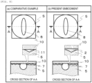
- FIG. 8 and (b) of FIG. 8 are views showing states of the surface facing the electrode body 5 and the ion-sensitive film 10 when the ion-sensitive film 10 is pressurized with the weight 4, in which (a) of FIG. 8 shows a case in which the water 2 is not used as in a comparative example, and (b) of FIG. 8 shows a case in which the water 2 is used as in the present embodiment.
- the thermal energy is uniformly transferred when the laser beam is emitted.
- the water 2 itself is evaporated by heat, melting on the placement surface 9 of the electrode body 5 is uniformly promoted, and the adhesion between the electrode body 5 and the ion-sensitive film 10 is improved.
- the bonding strength between the electrode body 5 and the ion-sensitive film 10 is increased, and thus it is possible to prevent a performance failure due to peeling of a response surface and to obtain stability of quality and a high yield rate.
Landscapes
- Chemical & Material Sciences (AREA)
- Life Sciences & Earth Sciences (AREA)
- Health & Medical Sciences (AREA)
- Physics & Mathematics (AREA)
- Chemical Kinetics & Catalysis (AREA)
- Electrochemistry (AREA)
- Molecular Biology (AREA)
- Analytical Chemistry (AREA)
- Biochemistry (AREA)
- General Health & Medical Sciences (AREA)
- General Physics & Mathematics (AREA)
- Immunology (AREA)
- Pathology (AREA)
- Investigating Or Analyzing Materials By The Use Of Electric Means (AREA)
- Measurement Of The Respiration, Hearing Ability, Form, And Blood Characteristics Of Living Organisms (AREA)
Abstract
Description
- The present invention relates to a method for manufacturing an ion sensor and an electrode member for an ion sensor.
- An ion sensor is used together with a reference electrode to measure a concentration of an ionic electrolyte in a sample, and is used by being mounted on an analysis device such as a clinical analysis device, a water quality analysis device, a soil analysis device, or a food analysis device.
- As an ion-sensitive film formed on a sensitive surface of the ion sensor, a film is known in the related art, which is obtained by, with a hydrophobic organic polymer such as polyvinyl chloride serving as a base, appropriately adding a plasticizer such as dibutyl phthalate (DBP), dipropyl phthalate (DPP), or 2-nitrophenyl octyl ether (NPOE) to the base, and mixing the base with an ion-sensitive substance such as valinomycin or a macrocyclic polyether derivative.
- The ion-sensitive film is prepared by applying a solvent solution, in which the organic polymer serving as the base of the ion-sensitive film and the ion-sensitive substance are dissolved in a volatile solvent at a predetermined ratio, to the sensitive surface of the ion sensor by brush application, dipping, dropwise adding, or the like so as to form an application film of the solution first, and then causing evaporation of the solvent to proceed while applying a stress in a direction of the sensitive surface. In this manner, when the solvent is evaporated while applying the stress as compared with a case of simple application and drying, an ion-sensitive film having a fairly smooth surface can be obtained, and an ion sensor in which an adverse effect due to adhesion of protein or the like is significantly prevented can be obtained.
- The ion sensor generally (for example, PTL 1) includes an electrode body, an internal solution, an ion-sensitive film, and an internal electrode. Here, the electrode body of a flow-type ion sensor includes a specimen flow path, and a through hole is provided in a part of a side surface of the specimen flow path. Then, the through hole is covered with the ion-sensitive film so as to form a response surface, and the ion-sensitive film and the electrode body are bonded to each other at a portion other than the response surface.
- PTL 1:
JPH11-132991A - A bonding operation of the ion-sensitive film and the electrode body is performed by dissolving the organic polymer that constitutes the ion-sensitive film and the electrode body once using a volatile solvent such as tetrahydrofuran (THF) at a bonding interface of the ion-sensitive film and the electrode body, and then evaporating the volatile solvent.
- Here, as a result of investigating a shape of the electrode body and a shape of the ion-sensitive film of the ion sensor and performance of the ion sensor, the inventors have noticed the following problems. That is, there are problems in that a bonding strength between the electrode body and the ion-sensitive film is weak and a response surface is easily peeled off due to a material variation in the electrode body and the ion-sensitive film, and a performance failure easily occurs when the response surface is peeled off.
- An object of the invention is to provide a method for manufacturing an ion sensor and an electrode member for an ion sensor, in which a bonding strength between the electrode body and an ion-sensitive film is improved regardless of a material variation so as to reduce occurrence of a performance failure.
- To solve the above problems, the invention provides a method for manufacturing an ion sensor in which an ion-sensitive film is bonded to an electrode member accommodating an internal solution and including an internal electrode. The method for manufacturing an ion sensor includes: an application step of applying water to a placement surface of an electrode body, in the electrode member, on which the ion-sensitive film is to be placed; a placement step of placing the ion-sensitive film in a state in which water is present on the placement surface; a pressurization step of pressurizing the ion-sensitive film from a side opposite to the electrode body; and an irradiation step of irradiating the ion-sensitive film with a laser beam from the side opposite to the electrode body in a state in which the ion-sensitive film is pressed against the electrode body.
- An electrode member for an ion sensor includes an internal electrode configured to output potential generated in an ion-sensitive film, and an electrode body accommodating an internal solution configured to electrically conduct the internal electrode and the ion-sensitive film. The electrode body includes a flow path through which a liquid containing a specimen to be measured flows, and a placement surface on which the ion-sensitive film is to be placed. A through portion that is exposed to the placement surface and brings the specimen into contact with the ion-sensitive film is formed at a predetermined position on an upper surface of the flow path. The ion-sensitive film and the placement surface are bonded to each other by pressurization and laser beam irradiation from above the ion-sensitive film in a state in which water is present in the placement surface other than the through portion.
- According to the invention, it is possible to provide a method for manufacturing an ion sensor and an electrode member for an ion sensor in which a bonding strength between the electrode body and an ion-sensitive film is improved regardless of a material variation so as to reduce occurrence of a performance failure.
-
- [
FIG. 1] FIG. 1 is an overall view showing a method for manufacturing an ion sensor according to an embodiment of the invention. - [
FIG. 2] FIG. 2 is a flowchart showing the method for manufacturing an ion sensor according to the embodiment of the invention. - [
FIG. 3] FIG. 3 is a view showing an application step in step S1 ofFIG. 2 . - [
FIG. 4] FIG. 4 is a view showing a placement step in step S2 ofFIG. 2 . - [
FIG. 5] FIG. 5 is a view showing a pressurization step in step S3 ofFIG. 2 . - [
FIG. 6] FIG. 6 is a view showing an irradiation step in step S4 ofFIG. 2 . - [
FIG. 7] FIG. 7 is a view showing an assembling step in step S5 ofFIG. 2 . - [
FIG. 8 ] (a) ofFIG. 8 and (b) ofFIG. 8 are views showing states of a surface facing an electrode body and an ion-sensitive film, in which (a) ofFIG. 8 shows a case in whichwater 2 is not used as in a comparative example, and (b) ofFIG. 8 shows a case in whichwater 2 is used as in the present embodiment. - Hereinafter, an embodiment of the invention will be described in detail with reference to the drawings.
-
FIG. 1 is an overall view showing an outline of a method for manufacturing an ion sensor 1 according to the present embodiment. In the method for manufacturing the ion sensor 1 according to the present embodiment,water 2, alaser irradiator 3, and aweight 4 are used. In anelectrode body 5, although a wall surface on a front side, which facilitates understanding of the present embodiment, is not shown, the wall surface similar to a wall surface on a back side is actually provided. - First, a configuration of an electrode member used in the ion sensor 1 will be described with reference to
FIG. 7 . The electrode member for an ion sensor includes aninternal electrode 14 that outputs potential generated in an ion-sensitive film, anelectrode body 5 accommodating an internal solution (not shown) that electrically conducts theinternal electrode 14 and the ion-sensitive film 10, anelectrode body pin 15 that seals the internal solution so as not to leak the internal solution, and anelectrode body plate 13 that serves as a bottom surface accommodating an internal container. - Here, the
electrode body 5 includes aspecimen flow path 7 which is formed inside theelectrode body 5 and through which a liquid containing a specimen to be measured flows, and a placement surface 9 (bonding surface) on which the ion-sensitive film 10 is to be placed. Theelectrode body 5 has a rectangular parallelepiped shape having an outer dimension of about 11 mm × 20 mm × 24 mm, thespecimen flow path 7 has a diameter of about 1 mm, and theplacement surface 9 has a size of about 5 mm × 5 mm. In addition, a part of thespecimen flow path 7 is formed with athrough portion 8, which has an oval shape of about 0.9 mm × 3 mm and is exposed to theplacement surface 9 to bring the specimen into contact with the ion-sensitive film 10. Regarding a material of theelectrode body 5, it is considered to use a thermoplastic resin or a hard resin containing a pigment for theentire electrode body 5. Alternatively, the pigment may be applied to theplacement surface 9 of theelectrode body 5 separately from a main body of the electrode body formed of the hard resin. In this manner, as a material that easily generates thermal energy, a material having a melting point lower than that of the ion-sensitive film is preferably used for at least theplacement surface 9 of theelectrode body 5. - Next, a method for manufacturing the ion sensor 1 will be described in detail with reference to
FIGS. 2 to 7 .FIG. 2 is a flowchart showing the method for manufacturing an ion sensor, andFIGS. 3 to 7 are views showing steps in the method for manufacturing an ion sensor. - First, the
water 2 is applied to theplacement surface 9 of the electrode body 5 (step S1).FIG. 3 is a view showing the application step in step S1. Since the water applied to theplacement surface 9 is held on a surface of theplacement surface 9 by surface tension, the water does not flow down from thethrough portion 8 to the specimen flow path. - Next, the ion-
sensitive film 10 is placed onto theplacement surface 9 of theelectrode body 5 from above in a state in which thewater 2 is present in theplacement surface 9 other than the through portion 8 (before thewater 2 is evaporated and disappears) (step S2).FIG. 4 is a view showing the placement step in step S2. Here, the ion-sensitive film 10 is formed of a soft or hard resin material having a diameter of 5 mm and a thickness of about 0.1 mm to 0.5 mm. The ion-sensitive film 10 transmits a wavelength in a far-infrared region and has a melting point higher than that of theelectrode body 5 on theplacement surface 9. - Thereafter, the ion-
sensitive film 10 is pressurized from a side opposite to the electrode body 5 (step S3) .FIG. 5 is a view showing the pressurization step in step S3. In the pressurization step, theweight 4 is used, and the ion-sensitive film 10 is pressed, by theweight 4, against theplacement surface 9 of theelectrode body 5 in a vertical direction with thewater 2 interposed between the ion-sensitive film 10 and theplacement surface 9. A force applied to the entire ion-sensitive film 10 by theweight 4 is about 10 N to 100 N, so that adhesion between the ion-sensitive film 10, thewater 2, and theelectrode body 5 is improved. Here, in addition to transparent glass such as quartz glass, ceramic and the like are also considered to be a material of theweight 4 as long as a wavelength in the far-infrared region is allowed to transmit the material, and the material is not limited thereto. In addition, a lower end surface of theweight 4, which is a side in contact with the ion-sensitive film 10, has approximately the same size as that of theplacement surface 9 of theelectrode body 5 and has a shape similar to that of theplacement surface 9. The pressurizing force may be obtained not only by the gravity of theweight 4 itself but also by using an external force provided by, such as a servo motor. - In subsequent steps, the ion-
sensitive film 10 is irradiated with a laser beam from above (the side opposite to the electrode body 5) in a state in which the ion-sensitive film 10 is pressed against the placement surface 9 (step S4).FIG. 6 is a view showing the irradiation step in step S4. The laser beam has a wavelength that is in the far-infrared region and is emitted from thelaser irradiator 3. When theentire placement surface 9 or theentire weight 4 is irradiated with the laser beam, energy of the laser beam is converted into thermal energy, and theplacement surface 9 of theelectrode body 5 is melted by heat generation. At this time, since a gap between a surface facing the ion-sensitive film 10 and theelectrode body 5 is filled with the water applied in the application step in step S1, the heat generated by the laser beam irradiation spreads over theplacement surface 9. An irradiation time of the laser beam is preferably about 1 second to 20 seconds in consideration of a time until which theplacement surface 9 of theelectrode body 5 is melted and cured. The irradiation step is performed while the pressurization step in step S3 is continued, and the ion-sensitive film 10 is pressed against theplacement surface 9 in a melted state, and thus the ion-sensitive film 10 and theplacement surface 9 are easily bonded to each other. Further, by performing the pressurization step for about 1 second to 20 seconds as well after the irradiation step is completed, a bonding strength with the ion-sensitive film 10 is also improved for theplacement surface 9 near the throughportion 8. - When the irradiation step and the pressurization step are completed, a final assembling step of the ion sensor 1 is started (step S5).
FIG. 7 is a view showing the assembling step in step S5. In the assembling step, first, theelectrode body plate 13 is bonded and fixed to theelectrode body 5, and theelectrode body 5 is filled with the internal solution fromhole portions 12. Further, after theinternal electrode 14 is inserted through onehole portion 12 and bonded and fixed to theelectrode body 5, theelectrode body pin 15 is inserted through theother hole portion 12 and bonded and fixed to theelectrode body 5. Thus, the manufacturing of the ion sensor 1 is completed. - Hereinafter, effects of the
water 2 in the method for manufacturing the ion sensor 1 according to the present embodiment will be described. (a) ofFIG. 8 and (b) ofFIG. 8 are views showing states of the surface facing theelectrode body 5 and the ion-sensitive film 10 when the ion-sensitive film 10 is pressurized with theweight 4, in which (a) ofFIG. 8 shows a case in which thewater 2 is not used as in a comparative example, and (b) ofFIG. 8 shows a case in which thewater 2 is used as in the present embodiment. Here, a case in which there is a variation in the material of theelectrode body 5 and unevenness is generated on theplacement surface 9 will be described as an example, but the same applies to a case in which there is a variation in the material of the ion-sensitive film 10. - First, in the case in which the
water 2 is not used as in the comparative example, as shown in (a) ofFIG. 8 , since a gap 11 is present, it is difficult to uniformly transfer the thermal energy toward between theelectrode body 5 and the ion-sensitive film 10 even when thelaser irradiator 3 emits the laser beam. - On the other hand, in the present embodiment, as shown in (b) of
FIG. 8 , since the gap between theelectrode body 5 and the ion-sensitive film 10 is filled with thewater 2, the thermal energy is uniformly transferred when the laser beam is emitted. Here, although thewater 2 itself is evaporated by heat, melting on theplacement surface 9 of theelectrode body 5 is uniformly promoted, and the adhesion between theelectrode body 5 and the ion-sensitive film 10 is improved. As a result, according to the present embodiment, even when theelectrode body 5 has a material variation, the bonding strength between theelectrode body 5 and the ion-sensitive film 10 is increased, and thus it is possible to prevent a performance failure due to peeling of a response surface and to obtain stability of quality and a high yield rate. - The above embodiment is described in detail for better understanding of the invention, and the invention is not necessarily limited to those including all configurations described above. Further, a part of the configuration of the embodiment may be added, deleted, or replaced with another configuration.
-
- 1:
- ion sensor
- 2:
- water
- 3:
- laser irradiator
- 4:
- weight
- 5:
- electrode body
- 7:
- specimen flow path
- 8:
- through portion
- 9:
- placement surface
- 10:
- ion-sensitive film
- 11:
- gap
- 12:
- hole portion
- 13:
- electrode body plate
- 14:
- internal electrode
- 15:
- electrode body pin
Claims (6)
- A method for manufacturing an ion sensor in which an ion-sensitive film is bonded to an electrode member accommodating an internal solution and including an internal electrode, the method for manufacturing an ion sensor comprising:an application step of applying water to a placement surface of an electrode body, in the electrode member, on which the ion-sensitive film is to be placed;a placement step of placing the ion-sensitive film in a state in which water is present on the placement surface;a pressurization step of pressurizing the ion-sensitive film from a side opposite to the electrode body; andan irradiation step of irradiating the ion-sensitive film with a laser beam from the side opposite to the electrode body in a state in which the ion-sensitive film is pressed against the electrode body.
- The method for manufacturing an ion sensor according to claim 1, wherein
a weight that transmits the laser beam is used in the pressurization step. - The method for manufacturing an ion sensor according to claim 1, wherein
the irradiation step is performed while the pressurization step is continued. - The method for manufacturing an ion sensor according to claim 1, wherein
a melting point of the placement surface of the electrode body is lower than that of the ion-sensitive film. - The method for manufacturing an ion sensor according to claim 4, wherein
the placement surface of the electrode body is provided with a material different from that of a main body of the electrode body. - An electrode member for an ion sensor, comprising:an internal electrode configured to output potential generated in an ion-sensitive film; andan electrode body accommodating an internal solution configured to electrically conduct the internal electrode and the ion-sensitive film, whereinthe electrode body includes a flow path through which a liquid containing a specimen to be measured flows, and a placement surface on which the ion-sensitive film is to be placed,a through portion, which is exposed to the placement surface and brings the specimen into contact with the ion-sensitive film, is formed at a predetermined position on an upper surface of the flow path, andthe ion-sensitive film and the placement surface are bonded to each other by pressurization and laser beam irradiation from above the ion-sensitive film in a state in which water is present in the placement surface other than the through portion.
Applications Claiming Priority (2)
| Application Number | Priority Date | Filing Date | Title |
|---|---|---|---|
| JP2020121933 | 2020-07-16 | ||
| PCT/JP2021/009783 WO2022014095A1 (en) | 2020-07-16 | 2021-03-11 | Method for manufacturing ion sensor, and electrode body for ion sensor |
Publications (2)
| Publication Number | Publication Date |
|---|---|
| EP4184156A1 true EP4184156A1 (en) | 2023-05-24 |
| EP4184156A4 EP4184156A4 (en) | 2024-08-21 |
Family
ID=79554691
Family Applications (1)
| Application Number | Title | Priority Date | Filing Date |
|---|---|---|---|
| EP21842112.1A Pending EP4184156A4 (en) | 2020-07-16 | 2021-03-11 | Method for manufacturing ion sensor, and electrode body for ion sensor |
Country Status (5)
| Country | Link |
|---|---|
| US (1) | US12429450B2 (en) |
| EP (1) | EP4184156A4 (en) |
| JP (1) | JP7408810B2 (en) |
| CN (1) | CN115698693B (en) |
| WO (1) | WO2022014095A1 (en) |
Families Citing this family (2)
| Publication number | Priority date | Publication date | Assignee | Title |
|---|---|---|---|---|
| CN121443940A (en) | 2023-07-21 | 2026-01-30 | 株式会社日立高新技术 | Electrode for ion sensor and manufacturing method of ion sensor |
| JP2025142458A (en) * | 2024-03-18 | 2025-10-01 | 株式会社日立ハイテク | Method for manufacturing a flow-type ion-selective electrode and flow-type ion-selective electrode |
Family Cites Families (16)
| Publication number | Priority date | Publication date | Assignee | Title |
|---|---|---|---|---|
| JPS559138A (en) * | 1978-07-07 | 1980-01-23 | Hitachi Ltd | Ion selective electrode |
| JPS59102153A (en) * | 1982-12-06 | 1984-06-13 | Hitachi Ltd | Ion selective electrode and manufacture thereof |
| US4459199A (en) * | 1982-12-21 | 1984-07-10 | The Foxboro Company | Ruggedized ion-responsive electrode and its manufacturing process |
| JPS6010163A (en) * | 1983-06-30 | 1985-01-19 | Toshiba Corp | Flow communication type ion sensor |
| US4687500A (en) * | 1984-09-05 | 1987-08-18 | Orion Research Inc. | Method for manufacturing an ion-sensitive electrode |
| CN1008181B (en) * | 1984-09-05 | 1990-05-30 | 奥里安研究公司 | Relating to improved ion-sensitive electrodes |
| JP2570146Y2 (en) * | 1993-10-26 | 1998-05-06 | 株式会社島津製作所 | Ion-selective electrode |
| JPH095293A (en) * | 1995-06-15 | 1997-01-10 | Horiba Ltd | Ion response sensor, manufacturing method thereof, and manufacturing method of MOSFET |
| JPH09210949A (en) * | 1996-01-31 | 1997-08-15 | Miura Co Ltd | Ion electrode manufacturing method |
| KR100474880B1 (en) * | 1997-01-24 | 2005-08-10 | 엘지전자 주식회사 | Solid ion sensor manufacturing method |
| JPH11132991A (en) * | 1997-10-29 | 1999-05-21 | Hitachi Ltd | Ion-selective electrode and method for producing the same |
| JPH11295261A (en) | 1998-04-14 | 1999-10-29 | Toshiba Corp | Ion-selective electrode and method for producing the same |
| JP2007049040A (en) * | 2005-08-11 | 2007-02-22 | Omron Corp | Joining method |
| JP2009066820A (en) | 2007-09-11 | 2009-04-02 | Kirin Brewery Co Ltd | Laser welding method for plastic member with water interposed |
| JP6783704B2 (en) * | 2017-05-31 | 2020-11-11 | 株式会社日立ハイテク | Anion-selective electrode and its manufacturing method |
| JP2025102153A (en) | 2023-12-26 | 2025-07-08 | ローム株式会社 | Display device and source driver |
-
2021
- 2021-03-11 JP JP2022536129A patent/JP7408810B2/en active Active
- 2021-03-11 US US18/015,636 patent/US12429450B2/en active Active
- 2021-03-11 WO PCT/JP2021/009783 patent/WO2022014095A1/en not_active Ceased
- 2021-03-11 CN CN202180039765.4A patent/CN115698693B/en active Active
- 2021-03-11 EP EP21842112.1A patent/EP4184156A4/en active Pending
Also Published As
| Publication number | Publication date |
|---|---|
| CN115698693B (en) | 2025-07-29 |
| JPWO2022014095A1 (en) | 2022-01-20 |
| US20230314361A1 (en) | 2023-10-05 |
| EP4184156A4 (en) | 2024-08-21 |
| JP7408810B2 (en) | 2024-01-05 |
| CN115698693A (en) | 2023-02-03 |
| WO2022014095A1 (en) | 2022-01-20 |
| US12429450B2 (en) | 2025-09-30 |
Similar Documents
| Publication | Publication Date | Title |
|---|---|---|
| US12429450B2 (en) | Method for manufacturing ion sensor, and electrode body for ion sensor | |
| JP4201877B2 (en) | Electrochemical biosensor | |
| US10912193B2 (en) | Structure, wiring board, substrate for wiring board, copper clad laminate, and method for manufacturing the structure | |
| US20130047417A1 (en) | Method for sealing package | |
| US8445263B2 (en) | Device for cellular electrophysiology sensor, cellular electrophysiology sensor using the device, and method for manufacturing the cellular electrophysiology sensor device | |
| DK2590743T3 (en) | Chip unit for use in a mikrofluidanalysesystem | |
| TW200528703A (en) | Method and device for detecting moisture in electroluminescence display devices | |
| JPWO2007049607A1 (en) | Measuring device, measuring apparatus and measuring method | |
| JP2012225827A (en) | Fluid handling device and fluid handling system | |
| EP2610613A1 (en) | Liquid membrane type ion-selective electrode | |
| CN115206892A (en) | Thin electronic device | |
| JP2012141170A (en) | Electrode device for electrochemical measurement chip | |
| JP3283125B2 (en) | Sheet type ion sensor and sensor device including the same | |
| US7793546B2 (en) | Ultrasonic flaw detection method and ultrasonic flaw detection device | |
| US20090177116A1 (en) | Body fluid sampling device and body fluid measuring device using the same | |
| JP4425891B2 (en) | Cell electrophysiological sensor and manufacturing method thereof | |
| JP7863452B2 (en) | Electrochemical measuring device, electrochemical sensor, and electrochemical measuring method | |
| JP2012237562A (en) | Radiation detection panel and radiographic image detector | |
| US20030164457A1 (en) | Non-destructive method for testing curing level of cured product of curable adhesive composition and manufacturing method of electronic devices | |
| WO2018119886A1 (en) | Oled display panel and packaging method for oled display panel | |
| WO2025022941A1 (en) | Electrode body for ion sensor and method for manufacturing ion sensor | |
| JP5283177B2 (en) | Barrier film water vapor permeability measuring instrument and measuring method | |
| Lai et al. | The process and reliability tests of glass-to-glass laser bonding for top-emission OLED device | |
| JP2010008399A (en) | Cell electrophysiologic sensor and its manufacturing method | |
| JP4462241B2 (en) | Cell electrophysiological sensor and manufacturing method thereof |
Legal Events
| Date | Code | Title | Description |
|---|---|---|---|
| STAA | Information on the status of an ep patent application or granted ep patent |
Free format text: STATUS: THE INTERNATIONAL PUBLICATION HAS BEEN MADE |
|
| PUAI | Public reference made under article 153(3) epc to a published international application that has entered the european phase |
Free format text: ORIGINAL CODE: 0009012 |
|
| STAA | Information on the status of an ep patent application or granted ep patent |
Free format text: STATUS: REQUEST FOR EXAMINATION WAS MADE |
|
| 17P | Request for examination filed |
Effective date: 20230216 |
|
| AK | Designated contracting states |
Kind code of ref document: A1 Designated state(s): AL AT BE BG CH CY CZ DE DK EE ES FI FR GB GR HR HU IE IS IT LI LT LU LV MC MK MT NL NO PL PT RO RS SE SI SK SM TR |
|
| DAV | Request for validation of the european patent (deleted) | ||
| DAX | Request for extension of the european patent (deleted) | ||
| A4 | Supplementary search report drawn up and despatched |
Effective date: 20240723 |
|
| RIC1 | Information provided on ipc code assigned before grant |
Ipc: G01N 27/333 20060101AFI20240717BHEP |
|
| STAA | Information on the status of an ep patent application or granted ep patent |
Free format text: STATUS: EXAMINATION IS IN PROGRESS |
|
| 17Q | First examination report despatched |
Effective date: 20260122 |
|
| GRAP | Despatch of communication of intention to grant a patent |
Free format text: ORIGINAL CODE: EPIDOSNIGR1 |
|
| STAA | Information on the status of an ep patent application or granted ep patent |
Free format text: STATUS: GRANT OF PATENT IS INTENDED |