EP4184085A1 - Valve block device, control method, vehicle cooling system and vehicle - Google Patents
Valve block device, control method, vehicle cooling system and vehicle Download PDFInfo
- Publication number
- EP4184085A1 EP4184085A1 EP21847159.7A EP21847159A EP4184085A1 EP 4184085 A1 EP4184085 A1 EP 4184085A1 EP 21847159 A EP21847159 A EP 21847159A EP 4184085 A1 EP4184085 A1 EP 4184085A1
- Authority
- EP
- European Patent Office
- Prior art keywords
- outlet
- inlet
- valve assembly
- coolant
- communicate
- Prior art date
- Legal status (The legal status is an assumption and is not a legal conclusion. Google has not performed a legal analysis and makes no representation as to the accuracy of the status listed.)
- Granted
Links
Images

















Classifications
-
- B—PERFORMING OPERATIONS; TRANSPORTING
- B60—VEHICLES IN GENERAL
- B60H—ARRANGEMENTS OF HEATING, COOLING, VENTILATING OR OTHER AIR-TREATING DEVICES SPECIALLY ADAPTED FOR PASSENGER OR GOODS SPACES OF VEHICLES
- B60H1/00—Heating, cooling or ventilating devices
- B60H1/00642—Control systems or circuits; Control members or indication devices for heating, cooling or ventilating devices
-
- B—PERFORMING OPERATIONS; TRANSPORTING
- B60—VEHICLES IN GENERAL
- B60H—ARRANGEMENTS OF HEATING, COOLING, VENTILATING OR OTHER AIR-TREATING DEVICES SPECIALLY ADAPTED FOR PASSENGER OR GOODS SPACES OF VEHICLES
- B60H1/00—Heating, cooling or ventilating devices
- B60H1/00271—HVAC devices specially adapted for particular vehicle parts or components and being connected to the vehicle HVAC unit
-
- B—PERFORMING OPERATIONS; TRANSPORTING
- B60—VEHICLES IN GENERAL
- B60H—ARRANGEMENTS OF HEATING, COOLING, VENTILATING OR OTHER AIR-TREATING DEVICES SPECIALLY ADAPTED FOR PASSENGER OR GOODS SPACES OF VEHICLES
- B60H1/00—Heating, cooling or ventilating devices
- B60H1/00271—HVAC devices specially adapted for particular vehicle parts or components and being connected to the vehicle HVAC unit
- B60H1/00278—HVAC devices specially adapted for particular vehicle parts or components and being connected to the vehicle HVAC unit for the battery
-
- B—PERFORMING OPERATIONS; TRANSPORTING
- B60—VEHICLES IN GENERAL
- B60H—ARRANGEMENTS OF HEATING, COOLING, VENTILATING OR OTHER AIR-TREATING DEVICES SPECIALLY ADAPTED FOR PASSENGER OR GOODS SPACES OF VEHICLES
- B60H1/00—Heating, cooling or ventilating devices
- B60H1/00485—Valves for air-conditioning devices, e.g. thermostatic valves
-
- B—PERFORMING OPERATIONS; TRANSPORTING
- B60—VEHICLES IN GENERAL
- B60H—ARRANGEMENTS OF HEATING, COOLING, VENTILATING OR OTHER AIR-TREATING DEVICES SPECIALLY ADAPTED FOR PASSENGER OR GOODS SPACES OF VEHICLES
- B60H1/00—Heating, cooling or ventilating devices
- B60H1/00642—Control systems or circuits; Control members or indication devices for heating, cooling or ventilating devices
- B60H1/00814—Control systems or circuits characterised by their output, for controlling particular components of the heating, cooling or ventilating installation
- B60H1/00878—Control systems or circuits characterised by their output, for controlling particular components of the heating, cooling or ventilating installation the components being temperature regulating devices
- B60H1/00899—Controlling the flow of liquid in a heat pump system
-
- B—PERFORMING OPERATIONS; TRANSPORTING
- B60—VEHICLES IN GENERAL
- B60H—ARRANGEMENTS OF HEATING, COOLING, VENTILATING OR OTHER AIR-TREATING DEVICES SPECIALLY ADAPTED FOR PASSENGER OR GOODS SPACES OF VEHICLES
- B60H1/00—Heating, cooling or ventilating devices
- B60H1/32—Cooling devices
- B60H1/3204—Cooling devices using compression
- B60H1/3228—Cooling devices using compression characterised by refrigerant circuit configurations
- B60H1/32284—Cooling devices using compression characterised by refrigerant circuit configurations comprising two or more secondary circuits, e.g. at evaporator and condenser side
-
- B—PERFORMING OPERATIONS; TRANSPORTING
- B60—VEHICLES IN GENERAL
- B60H—ARRANGEMENTS OF HEATING, COOLING, VENTILATING OR OTHER AIR-TREATING DEVICES SPECIALLY ADAPTED FOR PASSENGER OR GOODS SPACES OF VEHICLES
- B60H1/00—Heating, cooling or ventilating devices
- B60H1/00357—Air-conditioning arrangements specially adapted for particular vehicles
- B60H1/00385—Air-conditioning arrangements specially adapted for particular vehicles for vehicles having an electrical drive, e.g. hybrid or fuel cell
- B60H1/00392—Air-conditioning arrangements specially adapted for particular vehicles for vehicles having an electrical drive, e.g. hybrid or fuel cell for electric vehicles having only electric drive means
-
- B—PERFORMING OPERATIONS; TRANSPORTING
- B60—VEHICLES IN GENERAL
- B60H—ARRANGEMENTS OF HEATING, COOLING, VENTILATING OR OTHER AIR-TREATING DEVICES SPECIALLY ADAPTED FOR PASSENGER OR GOODS SPACES OF VEHICLES
- B60H1/00—Heating, cooling or ventilating devices
- B60H1/00271—HVAC devices specially adapted for particular vehicle parts or components and being connected to the vehicle HVAC unit
- B60H2001/00307—Component temperature regulation using a liquid flow
-
- B—PERFORMING OPERATIONS; TRANSPORTING
- B60—VEHICLES IN GENERAL
- B60H—ARRANGEMENTS OF HEATING, COOLING, VENTILATING OR OTHER AIR-TREATING DEVICES SPECIALLY ADAPTED FOR PASSENGER OR GOODS SPACES OF VEHICLES
- B60H1/00—Heating, cooling or ventilating devices
- B60H1/00642—Control systems or circuits; Control members or indication devices for heating, cooling or ventilating devices
- B60H1/00814—Control systems or circuits characterised by their output, for controlling particular components of the heating, cooling or ventilating installation
- B60H1/00878—Control systems or circuits characterised by their output, for controlling particular components of the heating, cooling or ventilating installation the components being temperature regulating devices
- B60H2001/00928—Control systems or circuits characterised by their output, for controlling particular components of the heating, cooling or ventilating installation the components being temperature regulating devices comprising a secondary circuit
-
- B—PERFORMING OPERATIONS; TRANSPORTING
- B60—VEHICLES IN GENERAL
- B60K—ARRANGEMENT OR MOUNTING OF PROPULSION UNITS OR OF TRANSMISSIONS IN VEHICLES; ARRANGEMENT OR MOUNTING OF PLURAL DIVERSE PRIME-MOVERS IN VEHICLES; AUXILIARY DRIVES FOR VEHICLES; INSTRUMENTATION OR DASHBOARDS FOR VEHICLES; ARRANGEMENTS IN CONNECTION WITH COOLING, AIR INTAKE, GAS EXHAUST OR FUEL SUPPLY OF PROPULSION UNITS IN VEHICLES
- B60K1/00—Arrangement or mounting of electrical propulsion units
-
- B—PERFORMING OPERATIONS; TRANSPORTING
- B60—VEHICLES IN GENERAL
- B60K—ARRANGEMENT OR MOUNTING OF PROPULSION UNITS OR OF TRANSMISSIONS IN VEHICLES; ARRANGEMENT OR MOUNTING OF PLURAL DIVERSE PRIME-MOVERS IN VEHICLES; AUXILIARY DRIVES FOR VEHICLES; INSTRUMENTATION OR DASHBOARDS FOR VEHICLES; ARRANGEMENTS IN CONNECTION WITH COOLING, AIR INTAKE, GAS EXHAUST OR FUEL SUPPLY OF PROPULSION UNITS IN VEHICLES
- B60K11/00—Arrangement in connection with cooling of propulsion units
- B60K11/02—Arrangement in connection with cooling of propulsion units with liquid cooling
-
- B—PERFORMING OPERATIONS; TRANSPORTING
- B60—VEHICLES IN GENERAL
- B60K—ARRANGEMENT OR MOUNTING OF PROPULSION UNITS OR OF TRANSMISSIONS IN VEHICLES; ARRANGEMENT OR MOUNTING OF PLURAL DIVERSE PRIME-MOVERS IN VEHICLES; AUXILIARY DRIVES FOR VEHICLES; INSTRUMENTATION OR DASHBOARDS FOR VEHICLES; ARRANGEMENTS IN CONNECTION WITH COOLING, AIR INTAKE, GAS EXHAUST OR FUEL SUPPLY OF PROPULSION UNITS IN VEHICLES
- B60K1/00—Arrangement or mounting of electrical propulsion units
- B60K2001/003—Arrangement or mounting of electrical propulsion units with means for cooling the electrical propulsion units
- B60K2001/005—Arrangement or mounting of electrical propulsion units with means for cooling the electrical propulsion units the electric storage means
-
- B—PERFORMING OPERATIONS; TRANSPORTING
- B60—VEHICLES IN GENERAL
- B60K—ARRANGEMENT OR MOUNTING OF PROPULSION UNITS OR OF TRANSMISSIONS IN VEHICLES; ARRANGEMENT OR MOUNTING OF PLURAL DIVERSE PRIME-MOVERS IN VEHICLES; AUXILIARY DRIVES FOR VEHICLES; INSTRUMENTATION OR DASHBOARDS FOR VEHICLES; ARRANGEMENTS IN CONNECTION WITH COOLING, AIR INTAKE, GAS EXHAUST OR FUEL SUPPLY OF PROPULSION UNITS IN VEHICLES
- B60K1/00—Arrangement or mounting of electrical propulsion units
- B60K2001/003—Arrangement or mounting of electrical propulsion units with means for cooling the electrical propulsion units
- B60K2001/006—Arrangement or mounting of electrical propulsion units with means for cooling the electrical propulsion units the electric motors
-
- F—MECHANICAL ENGINEERING; LIGHTING; HEATING; WEAPONS; BLASTING
- F25—REFRIGERATION OR COOLING; COMBINED HEATING AND REFRIGERATION SYSTEMS; HEAT PUMP SYSTEMS; MANUFACTURE OR STORAGE OF ICE; LIQUEFACTION SOLIDIFICATION OF GASES
- F25B—REFRIGERATION MACHINES, PLANTS OR SYSTEMS; COMBINED HEATING AND REFRIGERATION SYSTEMS; HEAT PUMP SYSTEMS
- F25B2600/00—Control issues
- F25B2600/25—Control of valves
-
- Y—GENERAL TAGGING OF NEW TECHNOLOGICAL DEVELOPMENTS; GENERAL TAGGING OF CROSS-SECTIONAL TECHNOLOGIES SPANNING OVER SEVERAL SECTIONS OF THE IPC; TECHNICAL SUBJECTS COVERED BY FORMER USPC CROSS-REFERENCE ART COLLECTIONS [XRACs] AND DIGESTS
- Y02—TECHNOLOGIES OR APPLICATIONS FOR MITIGATION OR ADAPTATION AGAINST CLIMATE CHANGE
- Y02T—CLIMATE CHANGE MITIGATION TECHNOLOGIES RELATED TO TRANSPORTATION
- Y02T10/00—Road transport of goods or passengers
- Y02T10/60—Other road transportation technologies with climate change mitigation effect
- Y02T10/70—Energy storage systems for electromobility, e.g. batteries
Definitions
- This application relates to the field of vehicles, and in particular, to a valve assembly apparatus, a control method, a vehicle cooling system, and a vehicle.
- a working principle of the heat pump technology is similar to a working principle of compressor refrigeration and is as follows:
- Low-temperature and low-pressure liquid refrigerant for example, Freon
- a high-temperature heat source for example, a powertrain or a battery pack assembly
- the gaseous refrigerant is then compressed into high-temperature and high-pressure gaseous refrigerant in a compressor, and the gaseous refrigerant releases heat to a low-temperature heat source (for example, a passenger cabin), and then is condensed into high-pressure liquid refrigerant in a condenser.
- the liquid refrigerant is then throttled into low-temperature and low-pressure liquid refrigerant by using a throttling element (for example, a capillary, a thermal expansion valve, or an electronic expansion valve), and flows back to the evaporator.
- a throttling element for example, a capillary, a thermal expansion valve, or an electronic expansion valve
- the passenger cabin can be heated, and the powertrain can be cooled.
- the refrigerant is delivered to the powertrain and the passenger cabin through a pipe, and the refrigerant needs to flow in the pipe. Therefore, a large amount of refrigerant needs to be used.
- low-flammable refrigerant with a very high unit price is required for use in the vehicle.
- a high pressure-resistant stop valve is further added at a position of connection between a main pipe and each branch pipe, to control flow of the refrigerant. In this case, there is an increase in costs.
- Embodiments of this application provide a valve assembly apparatus, a control method, a vehicle cooling system, and a vehicle, to reduce costs of performing cooling or heating in a vehicle by using a heat pump.
- a valve assembly apparatus includes a controller, an actuator, a first inlet and outlet set, and a second inlet and outlet set.
- the first inlet and outlet set includes a first coolant inlet and outlet and a second coolant inlet and outlet.
- the second inlet and outlet set includes one or more of the following inlets and outlets: a powertrain inlet and outlet, a passenger cabin heating inlet and outlet, and a front end inlet and outlet.
- An inlet in the inlet and outlet is configured to allow inflow of coolant, and an outlet in the inlet and outlet is configured to allow outflow of coolant.
- An inlet in the first coolant inlet and outlet is configured to be connected to a coolant outlet of an evaporator in a heat pump subsystem, and an outlet in the first coolant inlet and outlet is configured to be connected to a coolant inlet of the evaporator.
- An inlet in the second coolant inlet and outlet is configured to be connected to a coolant outlet of a condenser in the heat pump subsystem, and an outlet in the second coolant inlet and outlet is configured to be connected to a coolant inlet of the condenser.
- an outlet in the powertrain inlet and outlet is configured to be connected to an inlet of a heat exchanger of a powertrain, and an inlet in the powertrain inlet and outlet is configured to be connected to an outlet of the heat exchanger of the powertrain.
- an outlet in the passenger cabin heating inlet and outlet is configured to be connected to an inlet of a heating heat exchanger of a passenger cabin, and an inlet in the passenger cabin heating inlet and outlet is configured to be connected to an outlet of the heating heat exchanger of the passenger cabin.
- the second inlet and outlet set includes the front end inlet and outlet
- an outlet in the front end inlet and outlet is configured to be connected to an inlet of a front end heat exchanger
- an inlet in the front end inlet and outlet is configured to be connected to an outlet of the front end heat exchanger.
- the controller is configured to control, based on a working condition of a vehicle cooling system, the actuator to communicate at least one inlet in the first inlet and outlet set with at least one outlet in the second inlet and outlet set, and communicate at least one outlet in the first inlet and outlet set with at least one inlet in the second inlet and outlet set.
- a full indirect cooling technology is used, a cooling capacity of the evaporator and a heating capacity of the condenser in the heat pump subsystem are conducted to a thermal management component terminal subsystem such as the powertrain, the passenger cabin, or the front end heat exchanger, and refrigerant does not need to be delivered to the thermal management component terminal subsystem, to ensure that the refrigerant and the passenger cabin are physically isolated, simplify a structure of the heat pump subsystem, reduce a quantity of high-pressure stop valves, and reduce refrigerant charge of the heat pump subsystem. Therefore, costs of performing cooling or heating in a vehicle by using a heat pump can be greatly reduced.
- the valve assembly apparatus further includes a first water tank and a second water tank; and the actuator includes a first valve assembly, a second valve assembly, a third valve assembly, a fourth valve assembly, and a fifth valve assembly, and each valve assembly includes a plurality of terminals;
- the first water tank is configured to store coolant that flows through the evaporator, and the second water tank is configured to store coolant that flows through the condenser;
- the outlet in the passenger cabin heating inlet and outlet is connected to a second terminal of the fourth valve assembly, and the inlet in the passenger cabin heating inlet and outlet is connected to the second water tank;
- the outlet in the powertrain inlet and outlet is connected to a fourth terminal of the first valve assembly and a first terminal of the fifth valve assembly, and the inlet in the powertrain inlet and outlet is connected to a first terminal of the third valve assembly;
- the outlet in the front end inlet and outlet is connected to a third terminal of the first valve assembly, a second terminal of the third valve assembly, and a first terminal
- valve assembly apparatus further includes a powertrain circulation pump, and the first terminal of the fifth valve assembly is connected to the outlet in the powertrain inlet and outlet by using the powertrain circulation pump.
- a powertrain circulation pump Another possible structure of the valve assembly apparatus is disclosed in this implementation.
- the second inlet and outlet set further includes a battery pack inlet and outlet, an outlet in the battery pack inlet and outlet is connected to the first terminal of the first valve assembly and the third terminal of the fourth valve assembly, and an inlet in the battery pack inlet and outlet is connected to a first terminal of the second valve assembly.
- valve assembly apparatus further includes a battery pack temperature compensation pump, and the outlet in the battery pack inlet and outlet is further connected to the inlet in the battery pack inlet and outlet by using the battery pack temperature compensation pump.
- a battery pack temperature compensation pump Another possible structure of the valve assembly apparatus is disclosed in this implementation.
- the second inlet and outlet set further includes a battery pack inlet and outlet, an outlet in the battery pack inlet and outlet is configured to be connected to an inlet of a heat exchanger of a battery pack assembly, and an inlet in the battery pack inlet and outlet is configured to be connected to an outlet of the heat exchanger of the battery pack assembly.
- the inlet and outlet set further includes a passenger cabin cooling inlet and outlet, an outlet in the passenger cabin cooling inlet and outlet is connected to a second terminal of the first valve assembly, and an inlet in the passenger cabin cooling inlet and outlet is connected to the first water tank.
- a passenger cabin cooling inlet and outlet is connected to a second terminal of the first valve assembly
- an inlet in the passenger cabin cooling inlet and outlet is connected to the first water tank.
- the inlet and outlet set further includes a passenger cabin cooling inlet and outlet, an outlet in the passenger cabin cooling inlet and outlet is configured to be connected to an inlet of a cooling heat exchanger of the passenger cabin, and an inlet in the passenger cabin cooling inlet and outlet is configured to be connected to an outlet of the cooling heat exchanger of the passenger cabin.
- the valve assembly apparatus may be further connected to the cooling heat exchanger of the passenger cabin, to cool the passenger cabin.
- the controller is configured to: when the working condition of the vehicle cooling system includes cooling the passenger cabin, control the actuator to communicate the inlet in the first coolant inlet and outlet with the outlet in the passenger cabin cooling inlet and outlet, and communicate the outlet in the first coolant inlet and outlet with the inlet in the passenger cabin cooling inlet and outlet.
- the actuator controls the actuator to communicate the inlet in the first coolant inlet and outlet with the outlet in the passenger cabin cooling inlet and outlet, and communicate the outlet in the first coolant inlet and outlet with the inlet in the passenger cabin cooling inlet and outlet.
- the controller is configured to: when the working condition of the vehicle cooling system includes heating the passenger cabin, control the actuator to communicate the inlet in the second coolant inlet and outlet with the outlet in the passenger cabin heating inlet and outlet, and communicate the outlet in the second coolant inlet and outlet with the inlet in the passenger cabin heating inlet and outlet.
- control the actuator to communicate the inlet in the second coolant inlet and outlet with the outlet in the passenger cabin heating inlet and outlet, and communicate the outlet in the second coolant inlet and outlet with the inlet in the passenger cabin heating inlet and outlet.
- the controller is configured to: when the working condition of the vehicle cooling system includes cooling the battery pack assembly, control the actuator to communicate the inlet in the first coolant inlet and outlet with the outlet in the battery pack inlet and outlet, and communicate the outlet in the first coolant inlet and outlet with the inlet in the battery pack inlet and outlet.
- the actuator controls the actuator to communicate the inlet in the first coolant inlet and outlet with the outlet in the battery pack inlet and outlet, and communicate the outlet in the first coolant inlet and outlet with the inlet in the battery pack inlet and outlet.
- the controller is configured to: when the working condition of the vehicle cooling system includes heating the battery pack assembly, control the actuator to communicate the inlet in the second coolant inlet and outlet with the outlet in the battery pack inlet and outlet, and communicate the outlet in the second coolant inlet and outlet with the inlet in the battery pack inlet and outlet.
- control the actuator to communicate the inlet in the second coolant inlet and outlet with the outlet in the battery pack inlet and outlet, and communicate the outlet in the second coolant inlet and outlet with the inlet in the battery pack inlet and outlet.
- the controller is configured to control the actuator to communicate the outlet in the battery pack inlet and outlet with the inlet in the battery pack inlet and outlet. Coolant that flows out from a heat exchanger of a battery pack and coolant that flows to the battery pack are mixed to increase a temperature of the coolant that flows to the battery pack, so that the battery pack works at an optimal working temperature, to avoid a case in which output power is reduced due to an excessively low temperature of the battery pack.
- the controller is configured to: when the working condition of the vehicle cooling system includes cooling the powertrain, control the actuator to communicate the inlet in the first coolant inlet and outlet with the outlet in the powertrain inlet and outlet, and communicate the outlet in the first coolant inlet and outlet with the inlet in the powertrain inlet and outlet.
- the actuator controls the actuator to communicate the inlet in the first coolant inlet and outlet with the outlet in the powertrain inlet and outlet, and communicate the outlet in the first coolant inlet and outlet with the inlet in the powertrain inlet and outlet.
- the controller is configured to: when the working condition of the vehicle cooling system includes cooling the powertrain, control the actuator to communicate the inlet in the first coolant inlet and outlet with the outlet in the front end inlet and outlet, communicate the inlet in the front end inlet and outlet with the outlet in the powertrain inlet and outlet, and communicate the inlet in the powertrain inlet and outlet with the outlet in the first coolant inlet and outlet.
- control the actuator to communicate the inlet in the first coolant inlet and outlet with the outlet in the front end inlet and outlet with the outlet in the powertrain inlet and outlet, and communicate the inlet in the powertrain inlet and outlet with the outlet in the first coolant inlet and outlet.
- the controller is configured to: when the working condition of the vehicle cooling system includes cooling the powertrain, control the actuator to communicate the inlet in the first coolant inlet and outlet with the outlet in the powertrain inlet and outlet, communicate the inlet in the powertrain inlet and outlet with the outlet in the front end inlet and outlet, and communicate the inlet in the front end inlet and outlet with the outlet in the first coolant inlet and outlet.
- control the actuator to communicate the inlet in the first coolant inlet and outlet with the outlet in the powertrain inlet and outlet with the outlet in the powertrain inlet and outlet, communicate the inlet in the powertrain inlet and outlet with the outlet in the front end inlet and outlet, and communicate the inlet in the front end inlet and outlet with the outlet in the first coolant inlet and outlet.
- heat exchange is performed with ambient air by using the front end heat exchanger, to increase a temperature of the coolant, so as to increase an evaporating temperature of refrigerant in the evaporator. Therefore, energy consumption for heating is reduced, and endurance mileage is increased.
- the controller is configured to: when the working condition of the vehicle cooling system includes performing natural heat dissipation on the powertrain, control the actuator to communicate the inlet in the second coolant inlet and outlet, the inlet in the powertrain inlet and outlet, and the outlet in the front end inlet and outlet, and communicate the outlet in the second coolant inlet and outlet, the outlet in the powertrain inlet and outlet, and the inlet in the front end inlet and outlet.
- Natural heat dissipation is performed on the powertrain, and cooling of the powertrain is omitted. Therefore, a rotational speed of a compressor can be reduced, and an evaporating temperature of refrigerant in the evaporator can be increased. Therefore, energy consumption for cooling is reduced, and endurance mileage is increased.
- the controller is configured to: when the working condition of the vehicle cooling system includes performing natural heat dissipation on the battery pack assembly and the powertrain, control the actuator to communicate the inlet in the first coolant inlet and outlet with the outlet in the powertrain inlet and outlet, communicate the inlet in the powertrain inlet and outlet with the outlet in the front end inlet and outlet, communicate the inlet in the front end inlet and outlet with the outlet in the second coolant inlet and outlet, communicate the inlet in the second coolant inlet and outlet with the outlet in the battery pack inlet and outlet, and communicate the inlet in the battery pack inlet and outlet with the outlet in the first coolant inlet and outlet.
- Heat generated by the battery pack assembly and heat generated by the powertrain are brought to the front end heat exchanger by using coolant, and are dissipated into air. Natural heat dissipation is performed on the battery pack assembly and the powertrain by using the front end heat exchanger, and a compressor does not need to be run. Therefore, energy consumption can be reduced, and endurance mileage can be increased.
- the controller is configured to: when the working condition of the vehicle cooling system includes performing natural heat dissipation on the battery pack assembly, control the actuator to communicate the inlet in the first coolant inlet and outlet with the outlet in the front end inlet and outlet, communicate the inlet in the front end inlet and outlet with the outlet in the second coolant inlet and outlet, communicate the inlet in the second coolant inlet and outlet with the outlet in the battery pack inlet and outlet, and communicate the inlet in the battery pack inlet and outlet with the outlet in the first coolant inlet and outlet.
- Heat generated by the battery pack assembly is brought to the front end heat exchanger by using coolant, and is dissipated into air. Natural heat dissipation is performed on the battery pack assembly by using the front end heat exchanger, and a compressor does not need to be run. Therefore, energy consumption can be reduced, and endurance mileage can be increased.
- the controller is configured to: when the working condition of the vehicle cooling system includes defrosting the front end heat exchanger, control the actuator to communicate the inlet in the front end inlet and outlet with the outlet in the powertrain inlet and outlet, and communicate the outlet in the front end inlet and outlet with the inlet in the powertrain inlet and outlet.
- the front end heat exchanger When the front end heat exchanger is defrosted, the heat pump subsystem does not need to work. Therefore, energy consumption can be reduced, and endurance mileage can be increased. Defrosting is performed by using residual heat of the powertrain, and defrosting can be performed without stopping a machine. Therefore, while thermal comfort of the passenger cabin in winter is ensured, defrosting is implemented with low energy consumption.
- the controller is further configured to: control the actuator to communicate the inlet in the second coolant inlet and outlet with the outlet in the front end inlet and outlet, and communicate the outlet in the second coolant inlet and outlet with the inlet in the front end inlet and outlet.
- Natural heat dissipation is performed on the condenser by using the front end heat exchanger, to reduce a condensing temperature of coolant in the condenser. Therefore, energy consumption for cooling is reduced, and endurance mileage is increased.
- the controller is further configured to: control the actuator to communicate the inlet in the first coolant inlet and outlet with the outlet in the front end inlet and outlet, and communicate the outlet in the first coolant inlet and outlet with the inlet in the front end inlet and outlet.
- a control method is provided, and is applied to the valve assembly apparatus in the first aspect.
- the method includes: A controller in the valve assembly apparatus controls, based on a working condition of a vehicle cooling system, an actuator in the valve assembly apparatus to communicate at least one inlet in a first inlet and outlet set of the valve assembly apparatus with at least one outlet in a second inlet and outlet set of the valve assembly apparatus, and communicate at least one outlet in the first inlet and outlet set with at least one inlet in the second inlet and outlet set.
- a full indirect cooling technology is used, a cooling capacity of an evaporator and a heating capacity of a condenser in a heat pump subsystem are conducted to a thermal management component terminal subsystem such as a powertrain, a passenger cabin, or a front end heat exchanger, and refrigerant does not need to be delivered to the thermal management component terminal subsystem, to ensure that the refrigerant and the passenger cabin are physically isolated, simplify a structure of the heat pump subsystem, reduce a quantity of high-pressure stop valves, and reduce refrigerant charge of the heat pump subsystem. Therefore, costs of performing cooling or heating in a vehicle by using a heat pump can be greatly reduced.
- the method further includes: The controller controls the actuator to communicate the outlet in the battery pack inlet and outlet with the inlet in the battery pack inlet and outlet.
- the method further includes: The controller controls the actuator to communicate an inlet in a second coolant inlet and outlet with an outlet in a front end inlet and outlet, and communicate an outlet in the second coolant inlet and outlet with an inlet in the front end inlet and outlet.
- the method further includes: The controller controls the actuator to communicate the inlet in the first coolant inlet and outlet with an outlet in a front end inlet and outlet, and communicate the outlet in the first coolant inlet and outlet with an inlet in the front end inlet and outlet.
- a vehicle cooling system includes a heat pump subsystem and the valve assembly apparatus according to any one of the first aspect and the implementations of the first aspect.
- the heat pump subsystem includes a condenser and an evaporator.
- the valve assembly apparatus is connected to a coolant outlet and a coolant inlet of the condenser, and the valve assembly apparatus is further connected to a coolant outlet and a coolant inlet of the evaporator.
- a vehicle is provided, and includes the vehicle cooling system according to the third aspect.
- Embodiments of this application provide a vehicle and a vehicle cooling system installed in the vehicle.
- the vehicle may be a fuel vehicle, a gas vehicle, an electric vehicle, or the like. This is not limited.
- the vehicle cooling system includes a heat pump subsystem 100, a flow path control subsystem 200, and a thermal management component terminal subsystem 300.
- the heat pump subsystem 100 includes but is not limited to a compressor 101, a liquid storage tank 102, an evaporator 103, a first throttling element 104, a condenser 105, and a second throttling element 106.
- the evaporator 103 communicates with the liquid storage tank 102
- the liquid storage tank 102 communicates with the compressor 101
- the compressor 101 communicates with the condenser 105
- the condenser 105 communicates with the evaporator 103 through the first throttling element 104.
- refrigerant is evaporated in the evaporator 103 for cooling, and is condensed in the condenser 105 for heating.
- the thermal management component terminal subsystem 300 includes but is not limited to a passenger cabin air handling assembly 302, a powertrain 303, and a front end heat exchanger 304.
- the thermal management component terminal subsystem 300 further includes a battery pack assembly 301.
- the battery pack assembly 301 includes but is not limited to a battery pack and a heat exchanger of the battery pack. Coolant flows in the heat exchanger of the battery pack, and is used to perform heat exchange with the battery pack, for example, used to dissipate heat for the battery pack in summer and heat the battery pack in winter.
- the passenger cabin air handling assembly 302 includes but is not limited to a cooling heat exchanger 3021 of a passenger cabin, a heating heat exchanger 3022 of the passenger cabin, and a direct expansion evaporator 3023. Coolant flows in the cooling heat exchanger 3021 (in a flow path 1 in the figure), to cool the passenger cabin. Coolant flows in the heating heat exchanger 3022 (in a flow path 2 in the figure), to heat the passenger cabin. Refrigerant flows in the direct expansion evaporator 3023, to cool the passenger cabin.
- the flow path control subsystem 200 includes but is not limited to an evaporator branch pump 201, a condenser branch pump 202, and a valve assembly apparatus 203. Coolant flows in the flow path control subsystem 200, and the evaporator branch pump 201 drives the coolant to exchange heat with refrigerant in the evaporator 103, to cool the coolant.
- the condenser branch pump 202 drives the coolant to exchange heat with refrigerant in the condenser 105, to heat the coolant.
- the valve assembly apparatus 203 is configured to: control a flow path of coolant, for example, isolate cooled coolant and heated coolant, and deliver the two types of coolant to different heat exchangers in the thermal management component terminal subsystem 300 based on a working condition of a heat exchange system.
- coolant for example, isolate cooled coolant and heated coolant
- the valve assembly apparatus 203 includes but is not limited to a controller, an actuator, a first inlet and outlet set, and a second inlet and outlet set, and optionally, further includes a feedback mechanism.
- the valve assembly apparatus 203 is connected to a coolant outlet and a coolant inlet of the condenser 105, and the valve assembly apparatus 203 is further connected to a coolant outlet and a coolant inlet of the evaporator 103.
- the first inlet and outlet set includes a first coolant inlet and outlet and a second coolant inlet and outlet.
- the second inlet and outlet set includes one or more of the following inlets and outlets: a powertrain inlet and outlet, a passenger cabin heating inlet and outlet, and a front end inlet and outlet.
- the second inlet and outlet set further includes a battery pack inlet and outlet.
- An inlet in the inlet and outlet is configured to allow inflow of coolant
- an outlet in the inlet and outlet is configured to allow outflow of coolant.
- the actuator includes but is not limited to a valve assembly and a water pump, and the actuator communicates with the first inlet and outlet set and the second inlet and outlet set.
- the feedback mechanism is configured to feed back an open/closed state of the valve assembly.
- the controller is configured to control, based on a working condition of the vehicle cooling system, the actuator to communicate at least one inlet in the first inlet and outlet set with at least one outlet in the second inlet and outlet set, and communicate at least one outlet in the first inlet and outlet set with at least one inlet in the second inlet and outlet set, in other words, control a flow path of coolant in the valve assembly apparatus 203.
- the actuator to communicate at least one inlet in the first inlet and outlet set with at least one outlet in the second inlet and outlet set, and communicate at least one outlet in the first inlet and outlet set with at least one inlet in the second inlet and outlet set, in other words, control a flow path of coolant in the valve assembly apparatus 203.
- the first coolant inlet and outlet includes an outlet OUT1 in the first coolant inlet and outlet and an inlet IN1 in the first coolant inlet and outlet.
- the second coolant inlet and outlet includes an outlet OUT2 in the second coolant inlet and outlet and an inlet IN2 in the second coolant inlet and outlet.
- the powertrain inlet and outlet includes an outlet OUT4 in the powertrain inlet and outlet and an inlet IN4 in the powertrain inlet and outlet.
- the passenger cabin heating inlet and outlet includes an outlet OUT5 in the passenger cabin heating inlet and outlet and an inlet IN5 in the passenger cabin heating inlet and outlet.
- the front end inlet and outlet includes an outlet OUT6 in the front end inlet and outlet and an inlet IN6 in the front end inlet and outlet.
- outlet OUT6 in the front end inlet and outlet
- inlet IN6 in the front end inlet and outlet
- FIG. 5 and FIG. 6 there is an outlet OUT3 in the battery pack inlet and outlet and an inlet IN3 in the battery pack inlet and outlet.
- the second inlet and outlet set may further include a passenger cabin cooling inlet and outlet.
- the passenger cabin cooling inlet and outlet includes an outlet OUT7 in the passenger cabin cooling inlet and outlet and an inlet IN7 in the passenger cabin cooling inlet and outlet.
- the inlet IN1 in the first coolant inlet and outlet is configured to be connected to the coolant outlet of the evaporator 103 (for example, by using the evaporator branch pump 201), and may be configured to allow coolant cooled by the evaporator 103 to flow to the valve assembly apparatus 203.
- the outlet OUT1 in the first coolant inlet and outlet is configured to be connected to the coolant inlet of the evaporator 103. After absorbing heat in the thermal management component terminal subsystem 300, the coolant cooled by the evaporator 103 flows from the valve assembly apparatus 203 to the evaporator 103 through the outlet OUT1 in the first coolant inlet and outlet.
- the inlet IN2 in the second coolant inlet and outlet is configured to be connected to the coolant outlet of the condenser 105 (for example, by using the condenser branch pump 202), and may be configured to allow coolant heated by the condenser 105 to flow to the valve assembly apparatus 203.
- the outlet OUT2 in the second coolant inlet and outlet is configured to be connected to the coolant inlet of the condenser 105. After dissipating heat in the thermal management component terminal subsystem 300, the coolant heated by the condenser 105 flows from the valve assembly apparatus 203 to the condenser 105 through the outlet OUT2 in the second coolant inlet and outlet.
- the outlet OUT3 in the battery pack inlet and outlet is configured to be connected to an inlet of the heat exchanger of the battery pack in the battery pack assembly 301, and may be configured to allow the coolant cooled by the evaporator 103 or the coolant heated by the condenser 105 to flow to the battery pack assembly 301; and the inlet IN3 in the battery pack inlet and outlet is configured to be connected to an outlet of the heat exchanger of the battery pack in the battery pack assembly 301, and may be configured to allow coolant for which heat exchange is performed by using the battery pack assembly 301 to flow to the valve assembly apparatus 203.
- the outlet OUT4 in the powertrain inlet and outlet is configured to be connected to an inlet of a heat exchanger of the powertrain 303, and may be configured to allow the coolant cooled by the evaporator 103 or the coolant heated by the condenser 105 to flow to the powertrain 303; and the inlet IN4 in the powertrain inlet and outlet is configured to be connected to an outlet of the heat exchanger of the powertrain 303, and may be configured to allow coolant for which heat exchange is performed by using the powertrain 303 to flow to the valve assembly apparatus 203.
- the outlet OUT5 in the passenger cabin heating inlet and outlet is configured to be connected to an inlet of the heating heat exchanger 3022 of the passenger cabin, may be configured to allow the coolant heated by the condenser 105 to flow to the heating heat exchanger 3022 of the passenger cabin; and the inlet IN5 in the passenger cabin heating inlet and outlet is configured to be connected to an outlet of the heating heat exchanger 3022 of the passenger cabin, and may be configured to allow coolant for which heat exchange is performed by using the heating heat exchanger 3022 of the passenger cabin to flow to the valve assembly apparatus 203.
- the outlet OUT6 in the front end inlet and outlet is configured to be connected to an inlet of the front end heat exchanger 304, and may be configured to allow the coolant cooled by the evaporator 103 or the coolant heated by the condenser 105 to flow to the front end heat exchanger 304; and the inlet IN6 in the front end inlet and outlet is configured to be connected to an outlet of the front end heat exchanger 304, and may be configured to allow coolant for which heat exchange is performed by using the front end heat exchanger 304 to flow to the valve assembly apparatus 203.
- the outlet OUT7 in the passenger cabin cooling inlet and outlet is configured to be connected to an inlet of the cooling heat exchanger 3021 of the passenger cabin, and may be configured to allow the coolant cooled by the evaporator 103 to flow to the cooling heat exchanger 3021 of the passenger cabin; and the inlet IN7 in the passenger cabin cooling inlet and outlet is configured to be connected to an outlet of the cooling heat exchanger 3021 of the passenger cabin, and may be configured to allow coolant for which heat exchange is performed by using the cooling heat exchanger 3021 of the passenger cabin to flow to the valve assembly apparatus 203.
- the coolant that flows to the valve assembly apparatus 203 from the inlet IN3 in the battery pack inlet and outlet may flow out from the outlet OUT6 in the front end inlet and outlet or the outlet OUT4 in the powertrain inlet and outlet
- the coolant that flows to the valve assembly apparatus 203 from the inlet IN4 in the powertrain inlet and outlet may flow out from the outlet OUT6 in the front end inlet and outlet
- the coolant that flows to the valve assembly apparatus 203 from the inlet IN6 in the front end inlet and outlet may flow out from the outlet OUT4 in the powertrain inlet and outlet.
- a structure of the valve assembly apparatus 203 is not limited in this application.
- the actuator in the valve assembly apparatus 203 includes a first valve assembly 2031, a second valve assembly 2032, a third valve assembly 2033, a fourth valve assembly 2034, and a fifth valve assembly 2035.
- the valve assembly apparatus 203 further includes a battery pack temperature compensation pump 2036, a powertrain circulation pump 2037, a first water tank 2038, and a second water tank 2039.
- the first water tank 2038 is configured to store coolant that flows through the evaporator 103
- the second water tank 2039 is configured to store coolant that flows through the condenser 105.
- the outlet OUT5 in the passenger cabin heating inlet and outlet is connected to a second terminal of the fourth valve assembly 2034, and the inlet IN5 in the passenger cabin heating inlet and outlet is connected to the second water tank 2039.
- the outlet OUT4 in the powertrain inlet and outlet is connected to a fourth terminal of the first valve assembly 2031 and a first terminal of the fifth valve assembly 2035, and the inlet IN4 in the powertrain inlet and outlet is connected to a first terminal of the third valve assembly 2033.
- the outlet OUT6 in the front end inlet and outlet is connected to a third terminal of the first valve assembly 2031, a second terminal of the third valve assembly 2033, and a first terminal of the fourth valve assembly 2034, and the inlet IN6 in the front end inlet and outlet is connected to a second terminal of the fifth valve assembly 2035.
- the inlet IN1 in the first coolant inlet and outlet is connected to a fifth terminal of the first valve assembly 2031, and the inlet IN2 in the second coolant inlet and outlet is connected to a fourth terminal of the fourth valve assembly 2034.
- the first water tank 2038 is further connected to a third terminal of the second valve assembly 2032, a third terminal of the fifth valve assembly 2035, and a third terminal of the third valve assembly 2033.
- the second water tank 2039 is further connected to a second terminal of the second valve assembly 2032, the fourth terminal of the first valve assembly 2031, and a fourth terminal of the fifth valve assembly 2035.
- a first terminal of the first valve assembly 2031 is connected to a third terminal of the fourth valve assembly 2034.
- the outlet OUT3 in the battery pack inlet and outlet is connected to the first terminal of the first valve assembly 2031 and the third terminal of the fourth valve assembly 2034, and the inlet IN3 in the battery pack inlet and outlet is connected to a first terminal of the second valve assembly 2032.
- the outlet OUT3 in the battery pack inlet and outlet is further connected to the inlet IN3 in the battery pack inlet and outlet by using the battery pack temperature compensation pump 2036.
- the outlet OUT7 in the passenger cabin cooling inlet and outlet is connected to a second terminal of the first valve assembly 2031, and the inlet IN7 in the passenger cabin cooling inlet and outlet is connected to the first water tank 2038.
- the first terminal of the fifth valve assembly 2035 is connected to the outlet OUT4 in the powertrain inlet and outlet by using the powertrain circulation pump 2037.
- Table 1 Scenario Passenger cabin Battery pack assembly Powertrain Front end heat exchanger * Heating Cooling Dehumidification Heating Cooling Natural cooling Heat recovery Natural cooling Active cooling Parking and charging Battery preheating ⁇ Colder Battery heat dissipation ⁇ Hotter Summer Normal running ⁇ ⁇ ⁇ Hotter Violent running ⁇ ⁇ ⁇ Hotter Spring and autumn Normal running ⁇ ⁇ ⁇ Hotter ⁇ ⁇ Hotter ⁇ ⁇ Winter Warm-up ⁇ ⁇ Colder Non-cooling dehumidification ⁇ ⁇ ⁇ ⁇ Colder Normal running ⁇ ⁇ ⁇ Colder ⁇ ⁇ ⁇ Colder Energy saving ⁇ ⁇ ⁇ Colder ⁇ ⁇ ⁇ Colder Defrosting ⁇ Colder, hotter
- the front end heat exchanger* represents that coolant that flows in the front end heat exchanger 304 is colder or hotter than ambient air.
- the controller in the valve assembly apparatus 203 may obtain an instruction for performing heat exchange (cooling or heating) on the passenger cabin, the battery pack assembly, or the powertrain from a host computer such as a vehicle running dynamic control system (vehicle running dynamic control system, VDC).
- a host computer such as a vehicle running dynamic control system (vehicle running dynamic control system, VDC).
- Normal running (non-violent running) at a high temperature in summer As shown in FIG. 9 and FIG. 10 , if the vehicle normally runs at a relatively high ambient temperature in summer, the passenger cabin and the battery pack assembly 301 are cooled by running the heat pump subsystem 100, the evaporator branch pump 201, and the condenser branch pump 202, and natural heat dissipation is performed on the powertrain 303 by using the front end heat exchanger 304.
- the controller controls the actuator to communicate the inlet IN1 in the first coolant inlet and outlet with the outlet OUT3 in the battery pack inlet and outlet, and communicate the outlet OUT1 in the first coolant inlet and outlet with the inlet IN3 in the battery pack inlet and outlet.
- the controller controls the fifth terminal of the first valve assembly 2031 to communicate with the first terminal, and controls the first terminal of the second valve assembly 2031 to communicate with the third terminal.
- the coolant circulates through the evaporator 103, the evaporator branch pump 201, the first valve assembly 2031, the heat exchanger of the battery pack assembly 301, the second valve assembly 2032, and the first water tank 2038.
- the controller further controls the battery pack temperature compensation pump 2036 to run, to mix coolant that flows out from the heat exchanger of the battery pack and coolant that flows to the battery pack to increase a temperature of the coolant that flows to the battery pack, so that the battery pack works at an optimal working temperature, to avoid a case in which output power is reduced due to an excessively low temperature of the battery pack.
- the temperature of the coolant is increased from 8 degrees to 20 degrees.
- the passenger cabin may be directly cooled by using the direct expansion evaporator 3023.
- the controller may control the actuator to communicate the inlet IN 1 in the first coolant inlet and outlet with the outlet OUT5 in the passenger cabin cooling inlet and outlet, and communicate the outlet OUT1 in the first coolant inlet and outlet with the inlet IN5 in the passenger cabin cooling inlet and outlet.
- the controller controls the fifth terminal of the first valve assembly 2031 to communicate with the second terminal.
- the coolant circulates through the evaporator 103, the evaporator branch pump 201, the first valve assembly 2031, the cooling heat exchanger 3021 of the passenger cabin, and the first water tank 2038.
- the controller controls the actuator to communicate the inlet IN2 in the second coolant inlet and outlet, the inlet IN4 in the powertrain inlet and outlet, and the outlet OUT6 in the front end inlet and outlet, and communicate the outlet OUT2 in the second coolant inlet and outlet, the outlet OUT4 in the powertrain inlet and outlet, and the inlet IN6 in the front end inlet and outlet.
- the controller controls the powertrain circulation pump 2037 to run, controls the first terminal of the third valve assembly 2033 to communicate with the second terminal, controls the fourth terminal of the fourth valve assembly 2034 to communicate with the first terminal, and controls the second terminal of the fifth valve assembly 2035 to communicate with the first terminal and the fourth terminal.
- a part of the coolant circulates through the condenser 105, the condenser branch pump 202, the fourth valve assembly 2034, the front end heat exchanger 304, the fifth valve assembly 2035, and the second water tank 2039.
- the other part of the coolant circulates through the front end heat exchanger 304, the fifth valve assembly 2035, the powertrain circulation pump 2037, the heat exchanger of the powertrain 303, and the third valve assembly 2033.
- the two parts of coolant are mixed in the front end heat exchanger 304. Therefore, the coolant in the front end heat exchanger 304 has a relatively high temperature, and heat exchange is performed with air to perform natural heat dissipation.
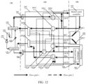
- FIG. 11 A difference between FIG. 11 and FIG. 9 lies in that there is no need to directly cool the passenger cabin by using the direct expansion evaporator 3023.
- a difference between FIG. 12 and FIG. 10 lies in that the controller does not need to control the actuator to communicate the inlet IN1 in the first coolant inlet and outlet with the outlet OUT5 in the passenger cabin cooling inlet and outlet, and does not need to control the actuator to communicate the outlet IN1 in the first coolant inlet and outlet with the inlet IN5 in the passenger cabin cooling inlet and outlet.
- the controller controls the fifth terminal of the first valve assembly 2031 to be disconnected from the second terminal.
- cooling of the passenger cabin is omitted. Therefore, a rotational speed of the compressor 101 can be reduced, and an evaporating temperature of refrigerant in the evaporator 103 can be increased. Therefore, energy consumption for cooling is reduced, and endurance mileage is increased.
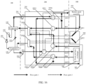
- Violent running at a high temperature in summer As shown in FIG. 13 and FIG. 14 , if the vehicle violently runs at a relatively high ambient temperature in summer, the powertrain 303 outputs high torque or a high rotational speed. In this case, heat generated by the powertrain 303 is increased, and the powertrain 303 cannot be effectively cooled if natural heat dissipation is performed on the powertrain 303. In this case, the passenger cabin, the battery pack assembly 301, and the powertrain 303 are cooled by running the heat pump subsystem 100, the evaporator branch pump 201, and the condenser branch pump 202, and natural heat dissipation is performed on the condenser 105 by using the front end heat exchanger 304.
- the controller controls the actuator to communicate the inlet IN1 in the first coolant inlet and outlet with the outlet OUT4 in the powertrain inlet and outlet, and communicate the outlet OUT1 in the first coolant inlet and outlet with the inlet IN4 in the powertrain inlet and outlet.
- the controller controls the fifth terminal of the first valve assembly 2031 to communicate with the fourth terminal, controls the first terminal of the third valve assembly 2033 to communicate with the third terminal, and controls the first terminal of the third valve assembly 2033 to be disconnected from the second terminal.
- the coolant circulates through the evaporator 103, the evaporator branch pump 201, the first valve assembly 2031, the heat exchanger of the powertrain 303, the third valve assembly 2033, and the first water tank 2038.
- the controller controls the actuator to communicate the inlet IN2 in the second coolant inlet and outlet with the outlet OUT6 in the front end inlet and outlet, and communicate the outlet in the second coolant inlet and outlet with the inlet IN6 in the front end inlet and outlet.
- the controller controls the first terminal of the fourth valve assembly 2034 to communicate with the fourth terminal, controls the second terminal of the fifth valve assembly 2035 to communicate with the fourth terminal, controls the second terminal of the fifth valve assembly 2035 to be disconnected from the first terminal, and controls the powertrain circulation pump 2037 to stop running.
- the coolant circulates through the condenser 105, the condenser branch pump 202, the fourth valve assembly 2034, the front end heat exchanger 304, the fifth valve assembly 2035, and the second water tank 2039.
- natural heat dissipation is performed on the condenser 105 by using the front end heat exchanger 304, to reduce a condensing temperature of coolant in the condenser 105. Therefore, energy consumption for cooling is reduced, and endurance mileage is increased.
- Violent running at an appropriate temperature in summer and in spring and autumn As shown in FIG. 15 and FIG. 16 , if the vehicle normally runs at a relatively appropriate ambient temperature in summer, there is no need to cool the passenger cabin, the battery pack assembly 301 and the powertrain 303 are cooled by running the heat pump subsystem 100, the evaporator branch pump 201, and the condenser branch pump 202, and natural heat dissipation is performed on the condenser 105 by using the front end heat exchanger 304, to reduce a condensing temperature of coolant in the condenser 105. Therefore, energy consumption for cooling is reduced, and endurance mileage is increased.
- FIG. 15 A difference between FIG. 15 and FIG. 13 lies in that there is no need to directly cool the passenger cabin by using the direct expansion evaporator 3023.
- a difference between FIG. 16 and FIG. 14 lies in that the controller does not need to control the actuator to communicate the inlet IN1 in the first coolant inlet and outlet with the outlet OUT5 in the passenger cabin cooling inlet and outlet, and does not need to control the actuator to communicate the outlet IN1 in the first coolant inlet and outlet with the inlet IN5 in the passenger cabin cooling inlet and outlet.
- the controller controls the fifth terminal of the first valve assembly 2031 to be disconnected from the second terminal.
- cooling of the passenger cabin is omitted. Therefore, a rotational speed of the compressor 101 can be reduced, and an evaporating temperature of refrigerant in the evaporator 103 can be increased. Therefore, energy consumption for cooling is reduced, and endurance mileage is increased.
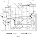
- Parking and charging in summer As shown in FIG. 17 and FIG. 18 , if the vehicle is parked and charged in summer and there is a relatively high ambient temperature, the battery pack assembly 301 is cooled by running the heat pump subsystem 100, the evaporator branch pump 201, and the condenser branch pump 202, and natural heat dissipation is performed on the condenser 105 by using the front end heat exchanger 304.
- the controller controls the battery pack temperature compensation pump 2036 and the powertrain circulation pump 2037 to stop running. If the passenger cabin needs to be cooled, the controller controls the battery pack temperature compensation pump 2036 to run, to mix a hot water part that flows out from the outlet of the heat exchanger of the battery pack into the inlet of the heat exchanger of the battery pack, so as to increase a temperature of coolant at the inlet of the heat exchanger of the battery pack, and ensure that a case in which a battery life is shortened due to an excessively low temperature of the coolant is avoided. If the passenger cabin does not need to be cooled, the controller controls the battery pack temperature compensation pump 2036 to stop running. For other content, refer to the description in FIG. 9 and FIG. 10 . No repeated description is provided herein.
- FIG. 17 and FIG. 15 A difference between FIG. 17 and FIG. 15 and a difference between FIG. 18 and FIG. 16 are as follows:
- the controller does not need to control the actuator to communicate the inlet IN1 in the first coolant inlet and outlet with the outlet OUT4 in the powertrain inlet and outlet, and does not need to control the actuator to communicate the outlet IN1 in the first coolant inlet and outlet with the inlet IN4 in the powertrain inlet and outlet.
- the controller controls the fifth terminal of the first valve assembly 2031 to be disconnected from the fourth terminal, controls the first terminal of the fourth valve assembly 2034 to be disconnected from the third terminal, and controls the battery pack temperature compensation pump 2036 and the powertrain circulation pump 2037 to stop working.
- cooling of the powertrain 303 is omitted. Therefore, a rotational speed of the compressor 101 can be reduced, and an evaporating temperature of refrigerant in the evaporator 103 can be increased.
- natural heat dissipation is performed on the condenser 105 by using the front end heat exchanger 304, to reduce a condensing temperature of coolant in the condenser 105. Therefore, energy consumption for cooling is reduced, and endurance mileage is increased.
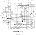
- the controller controls the actuator to communicate the inlet IN1 in the first coolant inlet and outlet with the outlet OUT4 in the powertrain inlet and outlet, communicate the inlet IN4 in the powertrain inlet and outlet with the outlet OUT6 in the front end inlet and outlet, communicate the inlet IN6 in the front end inlet and outlet with the outlet OUT2 in the second coolant inlet and outlet, communicate the inlet IN2 in the second coolant inlet and outlet with the outlet OUT3 in the battery pack inlet and outlet, and communicate the inlet IN3 in the battery pack inlet and outlet with the outlet OUT1 in the first coolant inlet and outlet.
- the controller controls the fifth terminal of the first valve assembly 2031 to communicate with the fourth terminal, controls the fifth terminal of the second valve assembly 2032 to communicate with the third terminal, controls the first terminal of the third valve assembly 2033 to communicate with the second terminal, controls the third terminal of the fourth valve assembly 2034 to communicate with the fourth terminal, controls the second terminal of the fifth valve assembly 2035 to communicate with the fifth terminal, and controls the battery pack temperature compensation pump 2036 and the powertrain circulation pump 2037 to stop working.
- the coolant circulates through the evaporator 103, the evaporator branch pump 201, the first valve assembly 2031, the heat exchanger of the powertrain 303, the third valve assembly 2033, the front end heat exchanger 304, the fifth valve assembly 2035, the second water tank 2039, the condenser 105, the condenser branch pump 202, the fourth valve assembly 2034, the heat exchanger of the battery pack assembly 301, the second valve assembly 2032, and the first water tank 2038.
- the controller controls the actuator to communicate the inlet IN 1 in the first coolant inlet and outlet with the outlet OUT6 in the front end inlet and outlet, communicate the inlet IN6 in the front end inlet and outlet with the outlet OUT2 in the second coolant inlet and outlet, communicate the inlet IN2 in the second coolant inlet and outlet with the outlet OUT3 in the battery pack inlet and outlet, and communicate the inlet IN3 in the battery pack inlet and outlet with the outlet OUT1 in the first coolant inlet and outlet.
- the controller controls the fifth terminal of the first valve assembly 2031 to communicate with the third terminal, controls the first terminal of the second valve assembly 2032 to communicate with the third terminal, controls the third terminal of the fourth valve assembly 2034 to communicate with the fourth terminal, controls the second terminal of the fifth valve assembly 2035 to communicate with the fourth terminal, and controls the battery pack temperature compensation pump 2036 and the powertrain circulation pump 2037 to stop working.
- the coolant circulates through the evaporator 103, the evaporator branch pump 201, the first valve assembly 2031, the front end heat exchanger 304, the fifth valve assembly 2035, the second water tank 2039, the condenser 105, the condenser branch pump 202, the fourth valve assembly 2034, the heat exchanger of the battery pack assembly 301, the second valve assembly 2032, and the first water tank 2038.
- the passenger cabin When the vehicle normally runs in winter, there is a relatively low ambient temperature. To ensure comfort of the passenger cabin, the passenger cabin is heated by running the heat pump subsystem 100, the evaporator branch pump 201, and the condenser branch pump 202, and heat generated by the battery pack assembly 301 and heat generated by the powertrain 303 are recovered (which is equivalent to cooling the battery pack assembly 301 and the powertrain 303).
- a very high heating capacity is determined for the condenser 105 in the heat pump subsystem 100 based on a relatively low ambient temperature, and correspondingly, there is a very high cooling capacity for the evaporator 103 in the heat pump subsystem 100.
- the powertrain 303 generates a very small amount of heat, a sum of heat generated by the battery pack assembly 301 and the heat generated by the powertrain 303 is still less than a cooling capacity of the heat pump subsystem 100, and a temperature of coolant that flows out from the evaporator 103 is less than the ambient temperature. Consequently, refrigerant in the evaporator 103 may have an excessively low evaporating temperature, and there is an increase in energy consumption for heating.
- the passenger cabin may be heated, the heat generated by the battery pack assembly 301 and the heat generated by the powertrain 303 may be recovered (which is equivalent to cooling the battery pack assembly 301 and the powertrain 303), and before coolant flows through the heat exchanger of the powertrain 303, heat exchange is performed between the coolant that flows through the evaporator 103 and ambient air by using the front end heat exchanger 304, to absorb heat from the ambient air, to increase the evaporating temperature of the refrigerant in the evaporator 103, so as to reduce energy consumption for heating and increase endurance mileage.
- the controller controls the actuator to communicate the inlet IN2 in the second coolant inlet and outlet with the outlet OUT5 in the passenger cabin heating inlet and outlet, and communicate the outlet OUT2 in the second coolant inlet and outlet with the inlet IN5 in the passenger cabin heating inlet and outlet.
- the controller controls the second terminal of the fourth valve assembly 2034 to communicate with the fourth terminal.
- the coolant circulates through the condenser 105, the condenser branch pump 202, the fourth valve assembly 2034, the heating heat exchanger 3022 of the passenger cabin, and the second water tank 2039.
- the controller controls the actuator to communicate the inlet IN1 in the first coolant inlet and outlet with the outlet OUT6 in the front end inlet and outlet, communicate the inlet IN6 in the front end inlet and outlet with the outlet OUT4 in the powertrain inlet and outlet, and communicate the inlet IN4 in the powertrain inlet and outlet with the outlet OUT1 in the first coolant inlet and outlet.
- the controller controls the fifth terminal of the first valve assembly 2031 to communicate with the third terminal, and controls the first terminal of the fifth valve assembly 2035 to communicate with the second terminal.
- the coolant circulates through the evaporator 103, the evaporator branch pump 201, the first valve assembly 2031, the front end heat exchanger 304, the fifth valve assembly 2035, the powertrain 303, the third valve assembly 2033, and the first water tank 2038.
- heat exchange is performed with the ambient air by using the front end heat exchanger 304, to increase a temperature of the coolant, so as to increase the evaporating temperature of the refrigerant in the evaporator 103. Therefore, energy consumption for heating is reduced, and endurance mileage is increased.
- the passenger cabin may be heated, and the heat generated by the battery pack assembly 301 and the heat generated by the powertrain 303 may be recovered (which is equivalent to cooling the battery pack assembly 301 and the powertrain 303), to reduce energy consumption for heating and increase endurance mileage.
- the coolant does not need to dissipate heat into the ambient air through the front end heat exchanger 304, to further increase an evaporating temperature of coolant in the evaporator 103. Therefore, while a pressure ratio of the compressor is reduced, energy consumption for heating can be reduced, and endurance mileage can be increased.
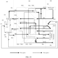
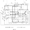
- Normal running 1-3 in winter In comparison with the implementation in FIG. 25 and FIG. 26 , as shown in FIG. 27 and FIG. 28 , as the powertrain 303 continuously generates heat, a temperature of coolant that flows out from the evaporator 103 continuously increases. When the temperature of the coolant that flows out from the evaporator 103 is higher than an ambient temperature plus a threshold due to an excessively large amount of heat generated by the powertrain 303, the compressor 101 is likely to be shut down due to an excessively high exhaust temperature. In this case, there is switching from a mode in FIG. 25 ( FIG. 26 ) to a mode in FIG. 27 ( FIG. 28 ).
- the passenger cabin may be heated, heat generated by the battery pack assembly 301 and the heat generated by the powertrain 303 may be recovered (which is equivalent to cooling the battery pack assembly 301 and the powertrain 303), and the coolant first flows through the heat exchanger of the powertrain 303, and then heat exchange is performed between the coolant that flows through the evaporator 103 and ambient air by using the front end heat exchanger 304, to dissipate heat into the ambient air, so as to reduce the exhaust temperature of the compressor 101 and prevent the compressor 101 from being shut down due to an excessively high exhaust temperature.
- the controller controls the actuator to communicate the inlet IN1 in the first coolant inlet and outlet with the outlet OUT4 in the powertrain inlet and outlet, communicate the inlet IN4 in the powertrain inlet and outlet with the outlet OUT6 in the front end inlet and outlet, and communicate the inlet IN6 in the front end inlet and outlet with the outlet OUT1 in the first coolant inlet and outlet.
- the controller controls the third terminal of the first valve assembly 2031 to communicate with the fourth terminal, controls the first terminal of the third valve assembly 2033 to communicate with the second terminal, and controls the second terminal of the fifth valve assembly 2035 to communicate with the fourth terminal.
- the coolant circulates through the evaporator 103, the evaporator branch pump 201, the first valve assembly 2031, the powertrain 303, the third valve assembly 2033, the front end heat exchanger 304, the fifth valve assembly 2035, and the first water tank 2038.
- heat exchange may be performed between the coolant that flows through the evaporator 103 and the ambient air by using the front end heat exchanger 304, to dissipate heat into the ambient air, so as to reduce the exhaust temperature of the compressor 101 and prevent the compressor 101 from being shut down due to an excessively high exhaust temperature.
- the battery pack assembly 301 When the ambient temperature in winter continues to decrease, and the battery pack assembly 301 generates a relatively small amount of heat, the passenger cabin needs to be heated, and the battery pack assembly 301 also needs to be heated.
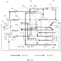
- FIG. 29 and FIG. 30 which are similar to FIG. 23 and FIG. 24 , the powertrain 303 generates a very small amount of heat in this case, and therefore a sum of heat generated by the battery pack assembly 301 and the heat generated by the powertrain 303 is still less than a cooling capacity of the heat pump subsystem 100.
- the passenger cabin and the battery pack assembly 301 may be heated, the heat generated by the powertrain 303 may be recovered (which is equivalent to cooling the powertrain 303), and before coolant flows through the heat exchanger of the powertrain 303, heat exchange is performed between the coolant that flows through the evaporator 103 and ambient air by using the front end heat exchanger 304, to absorb heat from the ambient air, to increase an evaporating temperature of refrigerant in the evaporator 103, so as to reduce energy consumption for heating, implement energy saving, and increase endurance mileage.
- the controller controls the actuator to communicate the inlet IN2 in the second coolant inlet and outlet with the outlet OUT3 in the battery pack inlet and outlet, and communicate the outlet OUT2 in the second coolant inlet and outlet with the inlet IN3 in the battery pack inlet and outlet.
- the controller controls the fifth terminal of the second valve assembly 2032 to communicate with the second terminal, controls the second terminal of the fourth valve assembly to communicate with the fourth terminal, and controls the battery pack temperature compensation pump 2036 to run.
- the coolant circulates through the condenser 105, the condenser branch pump 202, the fourth valve assembly 2034, the heat exchanger of the battery pack assembly 301, the second valve assembly 2032, and the second water tank 2039.
- the coolant absorbs the heat generated by the powertrain 303
- heat exchange is performed with the ambient air by using the front end heat exchanger 304, to increase a temperature of the coolant, so as to increase the evaporating temperature of the refrigerant in the evaporator 103. Therefore, energy consumption for heating is reduced, energy saving is implemented, and endurance mileage is increased.
- the battery pack assembly 301 is heated, to improve discharge efficiency and increase a service life of the battery pack in a running process, so that a requirement for preheating the battery pack before the battery pack is quickly charged can be met.
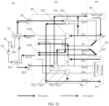
- FIG. 31 and FIG. 32 which are similar to FIG. 25 and FIG. 26 , as the powertrain 303 continuously generates heat, a sum of heat generated by the battery pack assembly 301 and the heat generated by the powertrain 303 is approximately equal to a cooling capacity of the heat pump subsystem 100, and a temperature of coolant that flows out from the evaporator 103 continuously increases.
- the temperature of the coolant is higher than an ambient temperature, there is switching from a mode in FIG. 29 ( FIG. 30 ) to a mode in FIG. 31 ( FIG. 32 ).
- the passenger cabin and the battery pack assembly 301 may be heated, and the heat generated by the powertrain 303 may be recovered (which is equivalent to cooling the powertrain 303), to reduce energy consumption for heating and increase endurance mileage.
- the heat generated by the powertrain 303 may be recovered (which is equivalent to cooling the powertrain 303), to reduce energy consumption for heating and increase endurance mileage.
- the coolant does not need to dissipate heat into the ambient air through the front end heat exchanger 304, to further increase an evaporating temperature of coolant in the evaporator 103. Therefore, while a pressure ratio of the compressor is reduced, energy consumption for heating can be reduced, and endurance mileage can be increased.
- FIG. 33 and FIG. 34 which are similar to FIG. 27 and FIG. 28 , as the powertrain 303 continuously generates heat, a temperature of coolant that flows out from the evaporator 103 continuously increases.
- the temperature of the coolant that flows out from the evaporator 103 is higher than an ambient temperature plus a threshold due to an excessively large amount of heat generated by the powertrain 303, the compressor 101 is likely to be shut down due to an excessively high exhaust temperature. In this case, there is switching from a mode in FIG. 31 ( FIG. 32 ) to a mode in FIG. 33 ( FIG. 34 ).
- the passenger cabin and the battery pack assembly 301 may be heated, the heat generated by the powertrain 303 may be recovered (which is equivalent to cooling the powertrain 303), and the coolant first flows through the heat exchanger of the powertrain 303, and then heat exchange is performed between the coolant that flows through the evaporator 103 and ambient air by using the front end heat exchanger 304, to dissipate heat into the ambient air, so as to reduce the exhaust temperature of the compressor 101 and prevent the compressor 101 from being shut down due to an excessively high exhaust temperature.
- heat exchange may be performed between the coolant that flows through the evaporator 103 and the ambient air by using the front end heat exchanger 304, to dissipate heat into the ambient air, so as to reduce the exhaust temperature of the compressor 101 and prevent the compressor 101 from being shut down due to an excessively high exhaust temperature.
- a human body exhales moisture in the passenger cabin, and therefore dehumidification may be implemented by condensing moisture in air through cooling.
- comfort of a passenger is reduced if cooling is performed in winter. Therefore, non-cooling dehumidification may be performed in winter. That is, when the passenger cabin is cooled by using the cooling heat exchanger 3021 of the passenger cabin or the direct expansion evaporator 3023, the passenger cabin is heated by using the heating heat exchanger 3022 of the passenger cabin.
- Non-cooling dehumidification 1-1 in winter As shown in FIG. 35 and FIG. 36 , which are similar to FIG. 23 and FIG. 24 , the powertrain 303 generates a very small amount of heat in this case, and therefore a sum of heat generated by the battery pack assembly 301 and the heat generated by the powertrain 303 is still less than a cooling capacity of the heat pump subsystem 100.
- the passenger cabin may be simultaneously cooled and heated, the heat generated by the battery pack assembly 301 and the heat generated by the powertrain 303 may be recovered (which is equivalent to cooling the battery pack assembly 301 and the powertrain 303), and before coolant flows through the heat exchanger of the powertrain 303, heat exchange is performed between the coolant that flows through the evaporator 103 and ambient air by using the front end heat exchanger 304, to absorb heat from the ambient air, to increase an evaporating temperature of refrigerant in the evaporator 103, so as to reduce energy consumption for heating, implement energy saving, and increase endurance mileage.
- heat exchange is performed with the ambient air by using the front end heat exchanger 304, to increase a temperature of the coolant, so as to increase the evaporating temperature of the refrigerant in the evaporator 103. Therefore, energy consumption for heating is reduced, energy saving is implemented, and endurance mileage is increased.
- Non-cooling dehumidification 1-2 in winter As shown in FIG. 37 and FIG. 38 , which are similar to FIG. 25 and FIG. 26 , as the powertrain 303 continuously generates heat, a sum of heat generated by the battery pack assembly 301 and the heat generated by the powertrain 303 is approximately equal to a cooling capacity of the heat pump subsystem 100, and a temperature of coolant that flows out from the evaporator 103 continuously increases. When the temperature of the coolant is higher than an ambient temperature, there is switching from a mode in FIG. 35 ( FIG. 36 ) to a mode in FIG. 37 ( FIG. 38 ).
- the passenger cabin may be simultaneously cooled and heated, and the heat generated by the battery pack assembly 301 and the heat generated by the powertrain 303 may be recovered (which is equivalent to cooling the battery pack assembly 301 and the powertrain 303), to reduce energy consumption for heating and increase endurance mileage.
- the coolant does not need to dissipate heat into the ambient air through the front end heat exchanger 304, to further increase an evaporating temperature of coolant in the evaporator 103. Therefore, while a pressure ratio of the compressor is reduced, energy consumption for heating can be reduced, and endurance mileage can be increased.
- Non-cooling dehumidification 1-3 in winter As shown in FIG. 39 and FIG. 40 , which are similar to FIG. 27 and FIG. 28 , as the powertrain 303 continuously generates heat, a temperature of coolant that flows out from the evaporator 103 continuously increases. When the temperature of the coolant that flows out from the evaporator 103 is higher than an ambient temperature plus a threshold due to an excessively large amount of heat generated by the powertrain 303, the compressor 101 is likely to be shut down due to an excessively high exhaust temperature. In this case, there is switching from a mode in FIG. 37 ( FIG. 38 ) to a mode in FIG. 39 ( FIG. 40 ).
- the passenger cabin may be simultaneously cooled and heated, heat generated by the battery pack assembly 301 and the heat generated by the powertrain 303 may be recovered (which is equivalent to cooling the battery pack assembly 301 and the powertrain 303), and the coolant first flows through the heat exchanger of the powertrain 303, and then heat exchange is performed between the coolant that flows through the evaporator 103 and ambient air by using the front end heat exchanger 304, to dissipate heat into the ambient air, so as to reduce the exhaust temperature of the compressor 101 and prevent the compressor 101 from being shut down due to an excessively high exhaust temperature.
- heat exchange may be performed between the coolant that flows through the evaporator 103 and the ambient air by using the front end heat exchanger 304, to dissipate heat into the ambient air, so as to reduce the exhaust temperature of the compressor 101 and prevent the compressor 101 from being shut down due to an excessively high exhaust temperature.
- the passenger cabin needs to be simultaneously cooled and heated, and the battery pack assembly 301 also needs to be heated.
- Non-cooling dehumidification 2-1 in winter As shown in FIG. 41 and FIG. 42 , which are similar to FIG. 29 and FIG. 30 , the powertrain 303 generates a very small amount of heat in this case, and therefore a sum of heat generated by the battery pack assembly 301 and the heat generated by the powertrain 303 is still less than a cooling capacity of the heat pump subsystem 100.
- the passenger cabin may be simultaneously cooled and heated, the battery pack assembly 301 may be heated, the heat generated by the powertrain 303 may be recovered (which is equivalent to cooling the powertrain 303), and before coolant flows through the heat exchanger of the powertrain 303, heat exchange is performed between the coolant that flows through the evaporator 103 and ambient air by using the front end heat exchanger 304, to absorb heat from the ambient air, to increase an evaporating temperature of refrigerant in the evaporator 103, so as to reduce energy consumption for heating and increase endurance mileage.
- heat exchange is performed with the ambient air by using the front end heat exchanger 304, to increase a temperature of the coolant, so as to increase the evaporating temperature of the refrigerant in the evaporator 103. Therefore, energy consumption for heating is reduced, and endurance mileage is increased.
- Non-cooling dehumidification 2-2 in winter As shown in FIG. 43 and FIG. 44 , which are similar to FIG. 31 and FIG. 32 , as the powertrain 303 continuously generates heat, a sum of heat generated by the battery pack assembly 301 and the heat generated by the powertrain 303 is approximately equal to a cooling capacity of the heat pump subsystem 100, and a temperature of coolant that flows out from the evaporator 103 continuously increases. When the temperature of the coolant is higher than an ambient temperature, there is switching from a mode in FIG. 41 ( FIG. 42 ) to a mode in FIG. 43 ( FIG. 44 ).
- the passenger cabin may be simultaneously cooled and heated, the battery pack assembly 301 may be heated, and the heat generated by the powertrain 303 may be recovered (which is equivalent to cooling the powertrain 303), to reduce energy consumption for heating and increase endurance mileage.
- the heat generated by the powertrain 303 may be recovered (which is equivalent to cooling the powertrain 303), to reduce energy consumption for heating and increase endurance mileage.
- the coolant does not need to dissipate heat into the ambient air through the front end heat exchanger 304, to further increase an evaporating temperature of coolant in the evaporator 103. Therefore, while a pressure ratio of the compressor is reduced, energy consumption for heating can be reduced, and endurance mileage can be increased.
- Non-cooling dehumidification 2-3 in winter As shown in FIG. 45 and FIG. 46 , which are similar to FIG. 33 and FIG. 34 , as the powertrain 303 continuously generates heat, a temperature of coolant that flows out from the evaporator 103 continuously increases. When the temperature of the coolant that flows out from the evaporator 103 is higher than an ambient temperature plus a threshold due to an excessively large amount of heat generated by the powertrain 303, the compressor 101 is likely to be shut down due to an excessively high exhaust temperature. In this case, there is switching from a mode in FIG. 31 ( FIG. 32 ) to a mode in FIG. 33 ( FIG. 34 ).
- the passenger cabin may be simultaneously cooled and heated, the battery pack assembly 301 may be heated, and the heat generated by the powertrain 303 may be recovered (which is equivalent to cooling the powertrain 303), and the coolant first flows through the heat exchanger of the powertrain 303, and then heat exchange is performed between the coolant that flows through the evaporator 103 and ambient air by using the front end heat exchanger 304, to dissipate heat into the ambient air, so as to reduce the exhaust temperature of the compressor 101 and prevent the compressor 101 from being shut down due to an excessively high exhaust temperature.
- heat exchange may be performed between the coolant that flows through the evaporator 103 and the ambient air by using the front end heat exchanger 304, to dissipate heat into the ambient air, so as to reduce the exhaust temperature of the compressor 101 and prevent the compressor 101 from being shut down due to an excessively high exhaust temperature.
- Defrosting of the front end heat exchanger in winter In a running process in winter, when an outdoor environment is within a temperature and humidity range of a frost area, as shown in FIG. 23 ( FIG. 24 ), FIG. 29 ( FIG. 30 ), FIG. 35 ( FIG. 36 ), and FIG. 41 ( FIG. 42 ), if heat exchange is performed between low-temperature coolant and ambient air in the front end heat exchanger 304, an airside fin of the front end heat exchanger 304 is likely to be frosted. To reduce energy consumption for defrosting and increase endurance mileage, defrosting may be performed by using a relatively high temperature of the ambient air in a manner shown in FIG. 25 ( FIG. 26 ), FIG. 31 ( FIG. 32 ), FIG. 37 ( FIG.
- defrosting may be performed by using the heat generated by the powertrain 303 in a manner shown in FIG. 27 ( FIG. 28 ), FIG. 33 ( FIG. 34 ), FIG. 39 ( FIG. 40 ), and FIG. 45 ( FIG. 46 ). In this case, there is a relatively short defrosting time.
- defrosting may be performed by using the heat generated by the powertrain 303 in a manner shown in FIG. 27 ( FIG. 28 ), FIG. 33 ( FIG. 34 ), FIG. 39 ( FIG. 40 ), and FIG. 45 ( FIG. 46 ).
- there is a relatively short defrosting time When the passenger cabin reaches a target temperature and the battery pack assembly 301 does not need to be cooled or heated, there may be switching to a mode shown in FIG. 47 or FIG. 48 .
- the front end heat exchanger 304 is defrosted by using the heat generated by the powertrain 303, and the controller controls the actuator to communicate the inlet IN6 in the front end inlet and outlet with the outlet OUT4 in the powertrain inlet and outlet, and communicate the outlet OUT6 in the front end inlet and outlet with the inlet IN4 in the powertrain inlet and outlet.
- the controller controls the first terminal of the third valve assembly 2033 to communicate with the second terminal, controls the first terminal of the fifth valve assembly 2035 to communicate with the second terminal, and controls the powertrain circulation pump 2037 to run.
- the heat pump subsystem 100 when the front end heat exchanger 304 is defrosted, the heat pump subsystem 100 does not need to work. Therefore, energy consumption can be reduced, and endurance mileage can be increased. Defrosting is performed by using residual heat of the powertrain 303, and defrosting can be performed without stopping a machine. Therefore, while thermal comfort of the passenger cabin in winter is ensured, defrosting is implemented with low energy consumption.
- the battery pack assembly 301 may be heated by running the heat pump subsystem 100, the evaporator branch pump 201, and the condenser branch pump 202, to reduce a charging time.
- the controller controls the battery pack temperature compensation pump 2036 and the powertrain circulation pump 2037 to stop running.
- the battery pack temperature compensation pump 2036 For other content, refer to the description in FIG. 29 and FIG. 30 . No repeated description is provided herein. This is because when the battery pack is charged in winter, the battery pack generates a very large amount of heat, and the battery pack does not need to output energy to the outside. Therefore, there is no need to use the battery pack temperature compensation pump 2036 to mix coolant that flows out from the heat exchanger of the battery pack and coolant that flows to the battery pack to increase a temperature of the coolant that flows to the battery pack, and there is no need to ensure that the battery pack works at an optimal working temperature.
- the controller further controls the actuator to communicate the inlet IN1 in the first coolant inlet and outlet with the outlet OUT6 in the front end inlet and outlet, and communicate the outlet OUT1 in the first coolant inlet and outlet with the inlet IN6 in the front end inlet and outlet.
- Heat exchange is performed between the coolant that flows through the evaporator 103 and ambient air by using the front end heat exchanger 304, to absorb heat from the ambient air, to increase an evaporating temperature of refrigerant in the evaporator 103, so as to reduce energy consumption for heating and increase endurance mileage.
- the controller controls the third terminal of the first valve assembly 2031 to communicate with the fifth terminal, and controls the second terminal of the fifth valve assembly 2035 to communicate with the fifth terminal.
- a full indirect cooling technology is used, a cooling capacity of the evaporator and a heating capacity of the condenser in the heat pump subsystem are conducted to a thermal management component terminal subsystem such as the powertrain, the passenger cabin, or the front end heat exchanger, and refrigerant does not need to be delivered to the thermal management component terminal subsystem, to ensure that the refrigerant and the passenger cabin are physically isolated, simplify a structure of the heat pump subsystem, reduce a quantity of high-pressure stop valves, and reduce refrigerant charge of the heat pump subsystem. Therefore, costs of performing cooling or heating in a vehicle by using a heat pump can be greatly reduced.
- each of the battery pack assembly, the powertrain, and the passenger cabin needs one front end heat exchanger.
- a quantity of cores in the front end heat exchanger is decreased from three cores to one core, to reduce costs and simplify mutual impact and a collaborative control policy.
- a heat pump heating technology with low energy consumption may be used for heating of both the passenger cabin and the battery pack in winter. In this way, heating efficiency can be effectively improved, energy consumption in winter can be reduced, and endurance mileage can be increased.
- natural heat dissipation may be independently performed on the battery pack, the battery pack and the powertrain may be connected in series for natural heat dissipation, and natural heat dissipation may be independently performed on the powertrain. Therefore, energy consumption for cooling is reduced, and endurance mileage is increased.
- the disclosed system, device, and method may be implemented in other manners.
- the described device embodiment is merely an example.
- division into the units is merely logical function division and may be other division in actual implementation.
- a plurality of units or components may be combined or integrated into another system, or some features may be ignored or not performed.
- the displayed or discussed mutual couplings or direct couplings or communication connections may be implemented through some interfaces.
- the indirect couplings or communication connections between the devices or units may be implemented in electrical, mechanical, or other forms
- the units described as separate parts may or may not be physically separate, and parts displayed as units may or may not be physical units, may be located in one position, or may be distributed on a plurality of network units. A part or all of the units may be selected based on actual requirements to achieve the objectives of the solutions of embodiments.
- All or a part of the foregoing embodiments may be implemented by using software, hardware, firmware, or any combination thereof.
- a software program is used to implement embodiments, all or some of embodiments may be implemented in a form of a computer program product.
- the computer program product includes one or more computer instructions.
- computer program instructions When computer program instructions are loaded and executed on a computer, all or a part of the procedures or functions according to embodiments of this application are generated.
- the computer may be a general-purpose computer, a dedicated computer, a computer network, or another programmable apparatus.
- the computer instructions may be stored in a computer-readable storage medium or may be transmitted from a computer-readable storage medium to another computer-readable storage medium.
- the computer instructions may be transmitted from a website, computer, server, or data center to another website, computer, server, or data center in a wired (for example, a coaxial cable, an optical fiber, or a digital subscriber line (Digital Subscriber Line, DSL)) or wireless (for example, infrared, radio, or microwave) manner.
- the computer-readable storage medium may be any usable medium accessible by a computer, or a data storage device, such as a server or a data center, integrating one or more usable media.
- the available medium may be a magnetic medium (for example, a floppy disk, a hard disk, or a magnetic tape), an optical medium (for example, a DVD), a semiconductor medium (for example, a solid-state disk (Solid State Disk, SSD)), or the like.
- a magnetic medium for example, a floppy disk, a hard disk, or a magnetic tape
- an optical medium for example, a DVD
- a semiconductor medium for example, a solid-state disk (Solid State Disk, SSD)
Landscapes
- Physics & Mathematics (AREA)
- Thermal Sciences (AREA)
- Engineering & Computer Science (AREA)
- Mechanical Engineering (AREA)
- Cooling, Air Intake And Gas Exhaust, And Fuel Tank Arrangements In Propulsion Units (AREA)
- Air-Conditioning For Vehicles (AREA)
- Hybrid Electric Vehicles (AREA)
Abstract
Description
- This application claims priority to
Chinese Patent Application No. 202010718784.7, filed with the China National Intellectual Property Administration on July 23, 2020 - This application relates to the field of vehicles, and in particular, to a valve assembly apparatus, a control method, a vehicle cooling system, and a vehicle.
- In a conventional vehicle cooling system for a vehicle, heat exchange is performed with a component of the vehicle by using an efficient heat pump technology. A working principle of the heat pump technology is similar to a working principle of compressor refrigeration and is as follows: Low-temperature and low-pressure liquid refrigerant (for example, Freon) absorbs heat from a high-temperature heat source (for example, a powertrain or a battery pack assembly), and is evaporated into low-pressure gaseous refrigerant in an evaporator. The gaseous refrigerant is then compressed into high-temperature and high-pressure gaseous refrigerant in a compressor, and the gaseous refrigerant releases heat to a low-temperature heat source (for example, a passenger cabin), and then is condensed into high-pressure liquid refrigerant in a condenser. The liquid refrigerant is then throttled into low-temperature and low-pressure liquid refrigerant by using a throttling element (for example, a capillary, a thermal expansion valve, or an electronic expansion valve), and flows back to the evaporator.
- It may be learned that in the heat pump technology, the passenger cabin can be heated, and the powertrain can be cooled. However, in the existing heat pump technology, the refrigerant is delivered to the powertrain and the passenger cabin through a pipe, and the refrigerant needs to flow in the pipe. Therefore, a large amount of refrigerant needs to be used. However, low-flammable refrigerant with a very high unit price is required for use in the vehicle. In addition, a high pressure-resistant stop valve is further added at a position of connection between a main pipe and each branch pipe, to control flow of the refrigerant. In this case, there is an increase in costs.
- Embodiments of this application provide a valve assembly apparatus, a control method, a vehicle cooling system, and a vehicle, to reduce costs of performing cooling or heating in a vehicle by using a heat pump.
- To achieve the foregoing objective, the following technical solutions are used in embodiments of this application.
- According to a first aspect, a valve assembly apparatus is provided, and includes a controller, an actuator, a first inlet and outlet set, and a second inlet and outlet set. The first inlet and outlet set includes a first coolant inlet and outlet and a second coolant inlet and outlet. The second inlet and outlet set includes one or more of the following inlets and outlets: a powertrain inlet and outlet, a passenger cabin heating inlet and outlet, and a front end inlet and outlet. An inlet in the inlet and outlet is configured to allow inflow of coolant, and an outlet in the inlet and outlet is configured to allow outflow of coolant. An inlet in the first coolant inlet and outlet is configured to be connected to a coolant outlet of an evaporator in a heat pump subsystem, and an outlet in the first coolant inlet and outlet is configured to be connected to a coolant inlet of the evaporator. An inlet in the second coolant inlet and outlet is configured to be connected to a coolant outlet of a condenser in the heat pump subsystem, and an outlet in the second coolant inlet and outlet is configured to be connected to a coolant inlet of the condenser. When the second inlet and outlet set includes the powertrain inlet and outlet, an outlet in the powertrain inlet and outlet is configured to be connected to an inlet of a heat exchanger of a powertrain, and an inlet in the powertrain inlet and outlet is configured to be connected to an outlet of the heat exchanger of the powertrain. When the second inlet and outlet set includes the passenger cabin heating inlet and outlet, an outlet in the passenger cabin heating inlet and outlet is configured to be connected to an inlet of a heating heat exchanger of a passenger cabin, and an inlet in the passenger cabin heating inlet and outlet is configured to be connected to an outlet of the heating heat exchanger of the passenger cabin. When the second inlet and outlet set includes the front end inlet and outlet, an outlet in the front end inlet and outlet is configured to be connected to an inlet of a front end heat exchanger, and an inlet in the front end inlet and outlet is configured to be connected to an outlet of the front end heat exchanger. The controller is configured to control, based on a working condition of a vehicle cooling system, the actuator to communicate at least one inlet in the first inlet and outlet set with at least one outlet in the second inlet and outlet set, and communicate at least one outlet in the first inlet and outlet set with at least one inlet in the second inlet and outlet set.
- In the valve assembly apparatus provided in this embodiment of this application, a full indirect cooling technology is used, a cooling capacity of the evaporator and a heating capacity of the condenser in the heat pump subsystem are conducted to a thermal management component terminal subsystem such as the powertrain, the passenger cabin, or the front end heat exchanger, and refrigerant does not need to be delivered to the thermal management component terminal subsystem, to ensure that the refrigerant and the passenger cabin are physically isolated, simplify a structure of the heat pump subsystem, reduce a quantity of high-pressure stop valves, and reduce refrigerant charge of the heat pump subsystem. Therefore, costs of performing cooling or heating in a vehicle by using a heat pump can be greatly reduced.
- In a possible implementation, the valve assembly apparatus further includes a first water tank and a second water tank; and the actuator includes a first valve assembly, a second valve assembly, a third valve assembly, a fourth valve assembly, and a fifth valve assembly, and each valve assembly includes a plurality of terminals; the first water tank is configured to store coolant that flows through the evaporator, and the second water tank is configured to store coolant that flows through the condenser; the outlet in the passenger cabin heating inlet and outlet is connected to a second terminal of the fourth valve assembly, and the inlet in the passenger cabin heating inlet and outlet is connected to the second water tank; the outlet in the powertrain inlet and outlet is connected to a fourth terminal of the first valve assembly and a first terminal of the fifth valve assembly, and the inlet in the powertrain inlet and outlet is connected to a first terminal of the third valve assembly; the outlet in the front end inlet and outlet is connected to a third terminal of the first valve assembly, a second terminal of the third valve assembly, and a first terminal of the fourth valve assembly, and the inlet in the front end inlet and outlet is connected to a second terminal of the fifth valve assembly; the inlet in the first coolant inlet and outlet is connected to a fifth terminal of the first valve assembly, and the inlet in the second coolant inlet and outlet is connected to a fourth terminal of the fourth valve assembly; the first water tank is further connected to a third terminal of the second valve assembly, a third terminal of the fifth valve assembly, and a third terminal of the third valve assembly; the second water tank is further connected to a second terminal of the second valve assembly, the fourth terminal of the first valve assembly, and a fourth terminal of the fifth valve assembly; and a first terminal of the first valve assembly is connected to a third terminal of the fourth valve assembly.
- In a possible implementation, the valve assembly apparatus further includes a powertrain circulation pump, and the first terminal of the fifth valve assembly is connected to the outlet in the powertrain inlet and outlet by using the powertrain circulation pump. Another possible structure of the valve assembly apparatus is disclosed in this implementation.
- In a possible implementation, the second inlet and outlet set further includes a battery pack inlet and outlet, an outlet in the battery pack inlet and outlet is connected to the first terminal of the first valve assembly and the third terminal of the fourth valve assembly, and an inlet in the battery pack inlet and outlet is connected to a first terminal of the second valve assembly.
- In a possible implementation, the valve assembly apparatus further includes a battery pack temperature compensation pump, and the outlet in the battery pack inlet and outlet is further connected to the inlet in the battery pack inlet and outlet by using the battery pack temperature compensation pump. Another possible structure of the valve assembly apparatus is disclosed in this implementation.
- In a possible implementation, the second inlet and outlet set further includes a battery pack inlet and outlet, an outlet in the battery pack inlet and outlet is configured to be connected to an inlet of a heat exchanger of a battery pack assembly, and an inlet in the battery pack inlet and outlet is configured to be connected to an outlet of the heat exchanger of the battery pack assembly.
- In a possible implementation, the inlet and outlet set further includes a passenger cabin cooling inlet and outlet, an outlet in the passenger cabin cooling inlet and outlet is connected to a second terminal of the first valve assembly, and an inlet in the passenger cabin cooling inlet and outlet is connected to the first water tank. Another possible structure of the valve assembly apparatus is disclosed in this implementation.
- In a possible implementation, the inlet and outlet set further includes a passenger cabin cooling inlet and outlet, an outlet in the passenger cabin cooling inlet and outlet is configured to be connected to an inlet of a cooling heat exchanger of the passenger cabin, and an inlet in the passenger cabin cooling inlet and outlet is configured to be connected to an outlet of the cooling heat exchanger of the passenger cabin. The valve assembly apparatus may be further connected to the cooling heat exchanger of the passenger cabin, to cool the passenger cabin.
- In a possible implementation, the controller is configured to: when the working condition of the vehicle cooling system includes cooling the passenger cabin, control the actuator to communicate the inlet in the first coolant inlet and outlet with the outlet in the passenger cabin cooling inlet and outlet, and communicate the outlet in the first coolant inlet and outlet with the inlet in the passenger cabin cooling inlet and outlet. During cooling of the passenger cabin, low-temperature coolant from the evaporator in the heat pump subsystem flows to the cooling heat exchanger of the passenger cabin, to cool the passenger cabin.
- In a possible implementation, the controller is configured to: when the working condition of the vehicle cooling system includes heating the passenger cabin, control the actuator to communicate the inlet in the second coolant inlet and outlet with the outlet in the passenger cabin heating inlet and outlet, and communicate the outlet in the second coolant inlet and outlet with the inlet in the passenger cabin heating inlet and outlet. During heating of the passenger cabin, high-temperature coolant from the condenser in the heat pump subsystem flows to the heating heat exchanger of the passenger cabin, to heat the passenger cabin.
- In a possible implementation, the controller is configured to: when the working condition of the vehicle cooling system includes cooling the battery pack assembly, control the actuator to communicate the inlet in the first coolant inlet and outlet with the outlet in the battery pack inlet and outlet, and communicate the outlet in the first coolant inlet and outlet with the inlet in the battery pack inlet and outlet. During cooling of the battery pack assembly, low-temperature coolant from the evaporator in the heat pump subsystem flows to the heat exchanger of the battery pack assembly, to cool the battery pack assembly.
- In a possible implementation, the controller is configured to: when the working condition of the vehicle cooling system includes heating the battery pack assembly, control the actuator to communicate the inlet in the second coolant inlet and outlet with the outlet in the battery pack inlet and outlet, and communicate the outlet in the second coolant inlet and outlet with the inlet in the battery pack inlet and outlet. During heating of the battery pack assembly, high-temperature coolant from the condenser in the heat pump subsystem flows to the heat exchanger of the battery pack assembly, to heat the battery pack assembly.
- In a possible implementation, the controller is configured to control the actuator to communicate the outlet in the battery pack inlet and outlet with the inlet in the battery pack inlet and outlet. Coolant that flows out from a heat exchanger of a battery pack and coolant that flows to the battery pack are mixed to increase a temperature of the coolant that flows to the battery pack, so that the battery pack works at an optimal working temperature, to avoid a case in which output power is reduced due to an excessively low temperature of the battery pack.
- In a possible implementation, the controller is configured to: when the working condition of the vehicle cooling system includes cooling the powertrain, control the actuator to communicate the inlet in the first coolant inlet and outlet with the outlet in the powertrain inlet and outlet, and communicate the outlet in the first coolant inlet and outlet with the inlet in the powertrain inlet and outlet. During cooling of the powertrain, low-temperature coolant from the evaporator in the heat pump subsystem flows to the heat exchanger of the powertrain, to cool the powertrain.
- In a possible implementation, the controller is configured to: when the working condition of the vehicle cooling system includes cooling the powertrain, control the actuator to communicate the inlet in the first coolant inlet and outlet with the outlet in the front end inlet and outlet, communicate the inlet in the front end inlet and outlet with the outlet in the powertrain inlet and outlet, and communicate the inlet in the powertrain inlet and outlet with the outlet in the first coolant inlet and outlet. During heating of the powertrain, high-temperature coolant from the condenser in the heat pump subsystem flows to the heat exchanger of the powertrain, to heat the powertrain.
- In a possible implementation, the controller is configured to: when the working condition of the vehicle cooling system includes cooling the powertrain, control the actuator to communicate the inlet in the first coolant inlet and outlet with the outlet in the powertrain inlet and outlet, communicate the inlet in the powertrain inlet and outlet with the outlet in the front end inlet and outlet, and communicate the inlet in the front end inlet and outlet with the outlet in the first coolant inlet and outlet. During cooling of the powertrain, low-temperature coolant from the evaporator in the heat pump subsystem flows to the heat exchanger of the powertrain, to cool the powertrain. In addition, before the coolant absorbs heat generated by the powertrain, heat exchange is performed with ambient air by using the front end heat exchanger, to increase a temperature of the coolant, so as to increase an evaporating temperature of refrigerant in the evaporator. Therefore, energy consumption for heating is reduced, and endurance mileage is increased.
- In a possible implementation, the controller is configured to: when the working condition of the vehicle cooling system includes performing natural heat dissipation on the powertrain, control the actuator to communicate the inlet in the second coolant inlet and outlet, the inlet in the powertrain inlet and outlet, and the outlet in the front end inlet and outlet, and communicate the outlet in the second coolant inlet and outlet, the outlet in the powertrain inlet and outlet, and the inlet in the front end inlet and outlet. Natural heat dissipation is performed on the powertrain, and cooling of the powertrain is omitted. Therefore, a rotational speed of a compressor can be reduced, and an evaporating temperature of refrigerant in the evaporator can be increased. Therefore, energy consumption for cooling is reduced, and endurance mileage is increased.
- In a possible implementation, the controller is configured to: when the working condition of the vehicle cooling system includes performing natural heat dissipation on the battery pack assembly and the powertrain, control the actuator to communicate the inlet in the first coolant inlet and outlet with the outlet in the powertrain inlet and outlet, communicate the inlet in the powertrain inlet and outlet with the outlet in the front end inlet and outlet, communicate the inlet in the front end inlet and outlet with the outlet in the second coolant inlet and outlet, communicate the inlet in the second coolant inlet and outlet with the outlet in the battery pack inlet and outlet, and communicate the inlet in the battery pack inlet and outlet with the outlet in the first coolant inlet and outlet. Heat generated by the battery pack assembly and heat generated by the powertrain are brought to the front end heat exchanger by using coolant, and are dissipated into air. Natural heat dissipation is performed on the battery pack assembly and the powertrain by using the front end heat exchanger, and a compressor does not need to be run. Therefore, energy consumption can be reduced, and endurance mileage can be increased.
- In a possible implementation, the controller is configured to: when the working condition of the vehicle cooling system includes performing natural heat dissipation on the battery pack assembly, control the actuator to communicate the inlet in the first coolant inlet and outlet with the outlet in the front end inlet and outlet, communicate the inlet in the front end inlet and outlet with the outlet in the second coolant inlet and outlet, communicate the inlet in the second coolant inlet and outlet with the outlet in the battery pack inlet and outlet, and communicate the inlet in the battery pack inlet and outlet with the outlet in the first coolant inlet and outlet. Heat generated by the battery pack assembly is brought to the front end heat exchanger by using coolant, and is dissipated into air. Natural heat dissipation is performed on the battery pack assembly by using the front end heat exchanger, and a compressor does not need to be run. Therefore, energy consumption can be reduced, and endurance mileage can be increased.
- In a possible implementation, the controller is configured to: when the working condition of the vehicle cooling system includes defrosting the front end heat exchanger, control the actuator to communicate the inlet in the front end inlet and outlet with the outlet in the powertrain inlet and outlet, and communicate the outlet in the front end inlet and outlet with the inlet in the powertrain inlet and outlet. When the front end heat exchanger is defrosted, the heat pump subsystem does not need to work. Therefore, energy consumption can be reduced, and endurance mileage can be increased. Defrosting is performed by using residual heat of the powertrain, and defrosting can be performed without stopping a machine. Therefore, while thermal comfort of the passenger cabin in winter is ensured, defrosting is implemented with low energy consumption.
- In a possible implementation, the controller is further configured to: control the actuator to communicate the inlet in the second coolant inlet and outlet with the outlet in the front end inlet and outlet, and communicate the outlet in the second coolant inlet and outlet with the inlet in the front end inlet and outlet. Natural heat dissipation is performed on the condenser by using the front end heat exchanger, to reduce a condensing temperature of coolant in the condenser. Therefore, energy consumption for cooling is reduced, and endurance mileage is increased.
- In a possible implementation, the controller is further configured to: control the actuator to communicate the inlet in the first coolant inlet and outlet with the outlet in the front end inlet and outlet, and communicate the outlet in the first coolant inlet and outlet with the inlet in the front end inlet and outlet. Before coolant absorbs heat generated by the powertrain, heat exchange is performed with ambient air by using the front end heat exchanger, to increase a temperature of the coolant, so as to increase an evaporating temperature of refrigerant in the evaporator. Therefore, energy consumption for heating is reduced, and endurance mileage is increased.
- According to a second aspect, a control method is provided, and is applied to the valve assembly apparatus in the first aspect. The method includes: A controller in the valve assembly apparatus controls, based on a working condition of a vehicle cooling system, an actuator in the valve assembly apparatus to communicate at least one inlet in a first inlet and outlet set of the valve assembly apparatus with at least one outlet in a second inlet and outlet set of the valve assembly apparatus, and communicate at least one outlet in the first inlet and outlet set with at least one inlet in the second inlet and outlet set.
- In the control method provided in this embodiment of this application, a full indirect cooling technology is used, a cooling capacity of an evaporator and a heating capacity of a condenser in a heat pump subsystem are conducted to a thermal management component terminal subsystem such as a powertrain, a passenger cabin, or a front end heat exchanger, and refrigerant does not need to be delivered to the thermal management component terminal subsystem, to ensure that the refrigerant and the passenger cabin are physically isolated, simplify a structure of the heat pump subsystem, reduce a quantity of high-pressure stop valves, and reduce refrigerant charge of the heat pump subsystem. Therefore, costs of performing cooling or heating in a vehicle by using a heat pump can be greatly reduced.
- In a possible implementation, that a controller in the valve assembly apparatus controls, based on a working condition of a vehicle cooling system, an actuator in the valve assembly apparatus to open at least one outlet and at least one inlet in an inlet and outlet set of the valve assembly apparatus includes: When the working condition of the vehicle cooling system includes cooling a passenger cabin, the controller controls the actuator to communicate an inlet in a first coolant inlet and outlet with an outlet in a passenger cabin cooling inlet and outlet, and communicate an outlet in the first coolant inlet and outlet with an inlet in the passenger cabin cooling inlet and outlet.
- In a possible implementation, that a controller in the valve assembly apparatus controls, based on a working condition of a vehicle cooling system, an actuator in the valve assembly apparatus to open at least one outlet and at least one inlet in an inlet and outlet set of the valve assembly apparatus includes: When the working condition of the vehicle cooling system includes heating the passenger cabin, the controller controls the actuator to communicate an inlet in a second coolant inlet and outlet with an outlet in a passenger cabin heating inlet and outlet, and communicate an outlet in the second coolant inlet and outlet with an inlet in the passenger cabin heating inlet and outlet.
- In a possible implementation, that a controller in the valve assembly apparatus controls, based on a working condition of a vehicle cooling system, an actuator in the valve assembly apparatus to open at least one outlet and at least one inlet in an inlet and outlet set of the valve assembly apparatus includes: When the working condition of the vehicle cooling system includes cooling a battery pack assembly, the controller controls the actuator to communicate the inlet in the first coolant inlet and outlet with an outlet in a battery pack inlet and outlet, and communicate the outlet in the first coolant inlet and outlet with an inlet in the battery pack inlet and outlet.
- In a possible implementation, that a controller in the valve assembly apparatus controls, based on a working condition of a vehicle cooling system, an actuator in the valve assembly apparatus to open at least one outlet and at least one inlet in an inlet and outlet set of the valve assembly apparatus includes: When the working condition of the vehicle cooling system includes heating a battery pack assembly, the controller controls the actuator to communicate the inlet in the second coolant inlet and outlet with an outlet in a battery pack inlet and outlet, and communicate the outlet in the second coolant inlet and outlet with an inlet in the battery pack inlet and outlet.
- In a possible implementation, the method further includes: The controller controls the actuator to communicate the outlet in the battery pack inlet and outlet with the inlet in the battery pack inlet and outlet.
- In a possible implementation, that a controller in the valve assembly apparatus controls, based on a working condition of a vehicle cooling system, an actuator in the valve assembly apparatus to open at least one outlet and at least one inlet in an inlet and outlet set of the valve assembly apparatus includes: When the working condition of the vehicle cooling system includes cooling a powertrain, the controller controls the actuator to communicate the inlet in the first coolant inlet and outlet with an outlet in a powertrain inlet and outlet, and communicate the outlet in the first coolant inlet and outlet with an inlet in the powertrain inlet and outlet.
- In a possible implementation, that a controller in the valve assembly apparatus controls, based on a working condition of a vehicle cooling system, an actuator in the valve assembly apparatus to open at least one outlet and at least one inlet in an inlet and outlet set of the valve assembly apparatus includes: When the working condition of the vehicle cooling system includes cooling a powertrain, the controller controls the actuator to communicate the inlet in the first coolant inlet and outlet with an outlet in a front end inlet and outlet, communicate an inlet in the front end inlet and outlet with an outlet in a powertrain inlet and outlet, and communicate an inlet in the powertrain inlet and outlet with the outlet in the first coolant inlet and outlet.
- In a possible implementation, that a controller in the valve assembly apparatus controls, based on a working condition of a vehicle cooling system, an actuator in the valve assembly apparatus to open at least one outlet and at least one inlet in an inlet and outlet set of the valve assembly apparatus includes: When the working condition of the vehicle cooling system includes cooling a powertrain, the controller controls the actuator to communicate the inlet in the first coolant inlet and outlet with an outlet in a powertrain inlet and outlet, communicate an inlet in the powertrain inlet and outlet with an outlet in a front end inlet and outlet, and communicate an inlet in the front end inlet and outlet with the outlet in the first coolant inlet and outlet.
- In a possible implementation, that a controller in the valve assembly apparatus controls, based on a working condition of a vehicle cooling system, an actuator in the valve assembly apparatus to open at least one outlet and at least one inlet in an inlet and outlet set of the valve assembly apparatus includes: When the working condition of the vehicle cooling system includes performing natural heat dissipation on a powertrain, the controller controls the actuator to communicate an inlet in a second coolant inlet and outlet, an inlet in a powertrain inlet and outlet, and an outlet in a front end inlet and outlet, and communicate an outlet in the second coolant inlet and outlet, an outlet in the powertrain inlet and outlet, and an inlet in the front end inlet and outlet.
- In a possible implementation, that a controller in the valve assembly apparatus controls, based on a working condition of a vehicle cooling system, an actuator in the valve assembly apparatus to open at least one outlet and at least one inlet in an inlet and outlet set of the valve assembly apparatus includes: when the working condition of the vehicle cooling system includes performing natural heat dissipation on a battery pack assembly and a powertrain, controlling the actuator to communicate an inlet in a first coolant inlet and outlet with an outlet in a powertrain inlet and outlet, communicate an inlet in the powertrain inlet and outlet with an outlet in a front end inlet and outlet, communicate an inlet in the front end inlet and outlet with an outlet in a second coolant inlet and outlet, communicate an inlet in the second coolant inlet and outlet with an outlet in a battery pack inlet and outlet, and communicate an inlet in the battery pack inlet and outlet with an outlet in the first coolant inlet and outlet.
- In a possible implementation, that a controller in the valve assembly apparatus controls, based on a working condition of a vehicle cooling system, an actuator in the valve assembly apparatus to open at least one outlet and at least one inlet in an inlet and outlet set of the valve assembly apparatus includes: When the working condition of the vehicle cooling system includes performing natural heat dissipation on a battery pack assembly, the controller controls the actuator to communicate an inlet in a first coolant inlet and outlet with an outlet in a front end inlet and outlet, communicate an inlet in the front end inlet and outlet with an outlet in a second coolant inlet and outlet, communicate an inlet in the second coolant inlet and outlet with an outlet in a battery pack inlet and outlet, and communicate an inlet in the battery pack inlet and outlet with an outlet in the first coolant inlet and outlet.
- In a possible implementation, that a controller in the valve assembly apparatus controls, based on a working condition of a vehicle cooling system, an actuator in the valve assembly apparatus to open at least one outlet and at least one inlet in an inlet and outlet set of the valve assembly apparatus includes: When the working condition of the vehicle cooling system includes defrosting a front end heat exchanger, the controller controls the actuator to communicate an inlet in a front end inlet and outlet with an outlet in a powertrain inlet and outlet, and communicate an outlet in the front end inlet and outlet with an inlet in the powertrain inlet and outlet.
- In a possible implementation, the method further includes: The controller controls the actuator to communicate an inlet in a second coolant inlet and outlet with an outlet in a front end inlet and outlet, and communicate an outlet in the second coolant inlet and outlet with an inlet in the front end inlet and outlet.
- In a possible implementation, the method further includes: The controller controls the actuator to communicate the inlet in the first coolant inlet and outlet with an outlet in a front end inlet and outlet, and communicate the outlet in the first coolant inlet and outlet with an inlet in the front end inlet and outlet.
- According to a third aspect, a vehicle cooling system is provided, and includes a heat pump subsystem and the valve assembly apparatus according to any one of the first aspect and the implementations of the first aspect. The heat pump subsystem includes a condenser and an evaporator. The valve assembly apparatus is connected to a coolant outlet and a coolant inlet of the condenser, and the valve assembly apparatus is further connected to a coolant outlet and a coolant inlet of the evaporator.
- According to a fourth aspect, a vehicle is provided, and includes the vehicle cooling system according to the third aspect.
- For technical effects of any one of the second aspect and the implementations of the second aspect to the fourth aspect, refer to any one of the first aspect and the implementations of the first aspect. No repeated description is provided herein.
-
-
FIG. 1 is a schematic diagram 1 of a structure of a vehicle cooling system according to an embodiment of this application; -
FIG. 2 is a schematic diagram 1 of a structure of another vehicle cooling system according to an embodiment of this application; -
FIG. 3 is a schematic diagram 1 of a structure of a vehicle cooling system and a valve assembly apparatus according to an embodiment of this application; -
FIG. 4 is a schematic diagram 1 of a structure of another vehicle cooling system and another valve assembly apparatus according to an embodiment of this application; -
FIG. 5 is a schematic diagram 2 of a structure of a vehicle cooling system according to an embodiment of this application; -
FIG. 6 is a schematic diagram 2 of a structure of another vehicle cooling system according to an embodiment of this application; -
FIG. 7 is a schematic diagram 2 of a structure of a vehicle cooling system and a valve assembly apparatus according to an embodiment of this application; -
FIG. 8 is a schematic diagram 2 of a structure of another vehicle cooling system and another valve assembly apparatus according to an embodiment of this application; -
FIG. 9 is a schematic diagram of a flow path of coolant existing during normal running at a high temperature in summer according to an embodiment of this application; -
FIG. 10 is another schematic diagram of a flow path of coolant existing during normal running at a high temperature in summer according to an embodiment of this application; -
FIG. 11 is a schematic diagram of a flow path of coolant existing during normal running at an appropriate temperature in summer according to an embodiment of this application; -
FIG. 12 is another schematic diagram of a flow path of coolant existing during normal running at an appropriate temperature in summer according to an embodiment of this application; -
FIG. 13 is a schematic diagram of a flow path of coolant existing during violent running at a high temperature in summer according to an embodiment of this application; -
FIG. 14 is another schematic diagram of a flow path of coolant existing during violent running at a high temperature in summer according to an embodiment of this application; -
FIG. 15 is a schematic diagram of a flow path of coolant existing during violent running at an appropriate temperature in summer and in spring and autumn according to an embodiment of this application; -
FIG. 16 is another schematic diagram of a flow path of coolant existing during violent running at an appropriate temperature in summer and in spring and autumn according to an embodiment of this application; -
FIG. 17 is a schematic diagram of a flow path of coolant existing during parking and charging in summer according to an embodiment of this application; -
FIG. 18 is another schematic diagram of a flow path of coolant existing during parking and charging in summer according to an embodiment of this application; -
FIG. 19 is a schematic diagram of a flow path of coolant existing during normal running at an appropriate temperature in spring and autumn according to an embodiment of this application; -
FIG. 20 is another schematic diagram of a flow path of coolant existing during normal running at an appropriate temperature in spring and autumn according to an embodiment of this application; -
FIG. 21 is a schematic diagram of a flow path of coolant existing during parking and charging in spring and autumn according to an embodiment of this application; -
FIG. 22 is another schematic diagram of a flow path of coolant existing during parking and charging in spring and autumn according to an embodiment of this application; -
FIG. 23 is a schematic diagram of a flow path of coolant existing during normal running 1-1 in winter according to an embodiment of this application; -
FIG. 24 is another schematic diagram of a flow path of coolant existing during normal running 1-1 in winter according to an embodiment of this application; -
FIG. 25 is a schematic diagram of a flow path of coolant existing during normal running 1-2 in winter according to an embodiment of this application; -
FIG. 26 is another schematic diagram of a flow path of coolant existing during normal running 1-2 in winter according to an embodiment of this application; -
FIG. 27 is a schematic diagram of a flow path of coolant existing during normal running 1-3 in winter according to an embodiment of this application; -
FIG. 28 is another schematic diagram of a flow path of coolant existing during normal running 1-3 in winter according to an embodiment of this application; -
FIG. 29 is a schematic diagram of a flow path of coolant existing during normal running 2-1 in winter according to an embodiment of this application; -
FIG. 30 is another schematic diagram of a flow path of coolant existing during normal running 2-1 in winter according to an embodiment of this application; -
FIG. 31 is a schematic diagram of a flow path of coolant existing during normal running 2-2 in winter according to an embodiment of this application; -
FIG. 32 is another schematic diagram of a flow path of coolant existing during normal running 2-2 in winter according to an embodiment of this application; -
FIG. 33 is a schematic diagram of a flow path of coolant existing during normal running 2-3 in winter according to an embodiment of this application; -
FIG. 34 is another schematic diagram of a flow path of coolant existing during normal running 2-3 in winter according to an embodiment of this application; -
FIG. 35 is a schematic diagram of a flow path of coolant existing during non-cooling dehumidification 1-1 in winter according to an embodiment of this application; -
FIG. 36 is another schematic diagram of a flow path of coolant existing during non-cooling dehumidification 1-1 in winter according to an embodiment of this application; -
FIG. 37 is a schematic diagram of a flow path of coolant existing during non-cooling dehumidification 1-2 in winter according to an embodiment of this application; -
FIG. 38 is another schematic diagram of a flow path of coolant existing during non-cooling dehumidification 1-2 in winter according to an embodiment of this application; -
FIG. 39 is a schematic diagram of a flow path of coolant existing during non-cooling dehumidification 1-3 in winter according to an embodiment of this application; -
FIG. 40 is another schematic diagram of a flow path of coolant existing during non-cooling dehumidification 1-3 in winter according to an embodiment of this application; -
FIG. 41 is a schematic diagram of a flow path of coolant existing during non-cooling dehumidification 2-1 in winter according to an embodiment of this application; -
FIG. 42 is another schematic diagram of a flow path of coolant existing during non-cooling dehumidification 2-1 in winter according to an embodiment of this application; -
FIG. 43 is a schematic diagram of a flow path of coolant existing during non-cooling dehumidification 2-2 in winter according to an embodiment of this application; -
FIG. 44 is another schematic diagram of a flow path of coolant existing during non-cooling dehumidification 2-2 in winter according to an embodiment of this application; -
FIG. 45 is a schematic diagram of a flow path of coolant existing during non-cooling dehumidification 2-3 in winter according to an embodiment of this application; -
FIG. 46 is another schematic diagram of a flow path of coolant existing during non-cooling dehumidification 2-3 in winter according to an embodiment of this application; -
FIG. 47 is a schematic diagram of a flow path of coolant existing during defrosting of a front end heat exchanger in winter according to an embodiment of this application; -
FIG. 48 is another schematic diagram of a flow path of coolant existing during defrosting of a front end heat exchanger in winter according to an embodiment of this application; -
FIG. 49 is a schematic diagram of a flow path of coolant existing during parking and charging in winter according to an embodiment of this application; and -
FIG. 50 is another schematic diagram of a flow path of coolant existing during parking and charging in winter according to an embodiment of this application. - The term "for example" in embodiments of this application is used to represent giving an example, an illustration, or a description. Any embodiment or design scheme described as an "example" in this application should not be explained as being more preferred or having more advantages than another embodiment or design scheme. Exactly, the word "example" is used to present a concept in a specific manner.
- Embodiments of this application provide a vehicle and a vehicle cooling system installed in the vehicle. The vehicle may be a fuel vehicle, a gas vehicle, an electric vehicle, or the like. This is not limited.
- As shown in
FIG. 1 andFIG. 2 , the vehicle cooling system includes aheat pump subsystem 100, a flowpath control subsystem 200, and a thermal managementcomponent terminal subsystem 300. - The
heat pump subsystem 100 includes but is not limited to acompressor 101, aliquid storage tank 102, anevaporator 103, afirst throttling element 104, acondenser 105, and asecond throttling element 106. Theevaporator 103 communicates with theliquid storage tank 102, theliquid storage tank 102 communicates with thecompressor 101, thecompressor 101 communicates with thecondenser 105, and thecondenser 105 communicates with theevaporator 103 through thefirst throttling element 104. In theheat pump subsystem 100, based on a heat pump principle described above, refrigerant is evaporated in theevaporator 103 for cooling, and is condensed in thecondenser 105 for heating. - The thermal management
component terminal subsystem 300 includes but is not limited to a passenger cabinair handling assembly 302, apowertrain 303, and a frontend heat exchanger 304. Optionally, as shown inFIG. 5 andFIG. 6 , the thermal managementcomponent terminal subsystem 300 further includes abattery pack assembly 301. - The
battery pack assembly 301 includes but is not limited to a battery pack and a heat exchanger of the battery pack. Coolant flows in the heat exchanger of the battery pack, and is used to perform heat exchange with the battery pack, for example, used to dissipate heat for the battery pack in summer and heat the battery pack in winter. The passenger cabinair handling assembly 302 includes but is not limited to acooling heat exchanger 3021 of a passenger cabin, aheating heat exchanger 3022 of the passenger cabin, and adirect expansion evaporator 3023. Coolant flows in the cooling heat exchanger 3021 (in aflow path 1 in the figure), to cool the passenger cabin. Coolant flows in the heating heat exchanger 3022 (in aflow path 2 in the figure), to heat the passenger cabin. Refrigerant flows in thedirect expansion evaporator 3023, to cool the passenger cabin. - The flow
path control subsystem 200 includes but is not limited to anevaporator branch pump 201, acondenser branch pump 202, and avalve assembly apparatus 203. Coolant flows in the flowpath control subsystem 200, and theevaporator branch pump 201 drives the coolant to exchange heat with refrigerant in theevaporator 103, to cool the coolant. Thecondenser branch pump 202 drives the coolant to exchange heat with refrigerant in thecondenser 105, to heat the coolant. Thevalve assembly apparatus 203 is configured to: control a flow path of coolant, for example, isolate cooled coolant and heated coolant, and deliver the two types of coolant to different heat exchangers in the thermal managementcomponent terminal subsystem 300 based on a working condition of a heat exchange system. - The
valve assembly apparatus 203 includes but is not limited to a controller, an actuator, a first inlet and outlet set, and a second inlet and outlet set, and optionally, further includes a feedback mechanism. Thevalve assembly apparatus 203 is connected to a coolant outlet and a coolant inlet of thecondenser 105, and thevalve assembly apparatus 203 is further connected to a coolant outlet and a coolant inlet of theevaporator 103. - The first inlet and outlet set includes a first coolant inlet and outlet and a second coolant inlet and outlet. The second inlet and outlet set includes one or more of the following inlets and outlets: a powertrain inlet and outlet, a passenger cabin heating inlet and outlet, and a front end inlet and outlet. Optionally, the second inlet and outlet set further includes a battery pack inlet and outlet. An inlet in the inlet and outlet is configured to allow inflow of coolant, and an outlet in the inlet and outlet is configured to allow outflow of coolant.
- The actuator includes but is not limited to a valve assembly and a water pump, and the actuator communicates with the first inlet and outlet set and the second inlet and outlet set. The feedback mechanism is configured to feed back an open/closed state of the valve assembly.
- The controller is configured to control, based on a working condition of the vehicle cooling system, the actuator to communicate at least one inlet in the first inlet and outlet set with at least one outlet in the second inlet and outlet set, and communicate at least one outlet in the first inlet and outlet set with at least one inlet in the second inlet and outlet set, in other words, control a flow path of coolant in the
valve assembly apparatus 203. For a specific control method performed by the controller, refer to description of the following scenarios. - As shown in
FIG. 1 andFIG. 2 , the first coolant inlet and outlet includes an outlet OUT1 in the first coolant inlet and outlet and an inlet IN1 in the first coolant inlet and outlet. The second coolant inlet and outlet includes an outlet OUT2 in the second coolant inlet and outlet and an inlet IN2 in the second coolant inlet and outlet. The powertrain inlet and outlet includes an outlet OUT4 in the powertrain inlet and outlet and an inlet IN4 in the powertrain inlet and outlet. The passenger cabin heating inlet and outlet includes an outlet OUT5 in the passenger cabin heating inlet and outlet and an inlet IN5 in the passenger cabin heating inlet and outlet. The front end inlet and outlet includes an outlet OUT6 in the front end inlet and outlet and an inlet IN6 in the front end inlet and outlet. Optionally, as shown inFIG. 5 andFIG. 6 , there is an outlet OUT3 in the battery pack inlet and outlet and an inlet IN3 in the battery pack inlet and outlet. - As shown in
FIG. 3 andFIG. 5 , when the passenger cabin is directly cooled by evaporating refrigerant by using thedirect expansion evaporator 3023, an outlet of thedirect expansion evaporator 3023 communicates with thecompressor 101, and an inlet of thedirect expansion evaporator 3023 communicates with thecondenser 105 through thesecond throttling element 106. - Optionally, as shown in
FIG. 4 andFIG. 6 , when the passenger cabin is indirectly cooled by using coolant, the second inlet and outlet set may further include a passenger cabin cooling inlet and outlet. The passenger cabin cooling inlet and outlet includes an outlet OUT7 in the passenger cabin cooling inlet and outlet and an inlet IN7 in the passenger cabin cooling inlet and outlet. - The inlet IN1 in the first coolant inlet and outlet is configured to be connected to the coolant outlet of the evaporator 103 (for example, by using the evaporator branch pump 201), and may be configured to allow coolant cooled by the
evaporator 103 to flow to thevalve assembly apparatus 203. The outlet OUT1 in the first coolant inlet and outlet is configured to be connected to the coolant inlet of theevaporator 103. After absorbing heat in the thermal managementcomponent terminal subsystem 300, the coolant cooled by theevaporator 103 flows from thevalve assembly apparatus 203 to theevaporator 103 through the outlet OUT1 in the first coolant inlet and outlet. The inlet IN2 in the second coolant inlet and outlet is configured to be connected to the coolant outlet of the condenser 105 (for example, by using the condenser branch pump 202), and may be configured to allow coolant heated by thecondenser 105 to flow to thevalve assembly apparatus 203. The outlet OUT2 in the second coolant inlet and outlet is configured to be connected to the coolant inlet of thecondenser 105. After dissipating heat in the thermal managementcomponent terminal subsystem 300, the coolant heated by thecondenser 105 flows from thevalve assembly apparatus 203 to thecondenser 105 through the outlet OUT2 in the second coolant inlet and outlet. - When the second inlet and outlet set includes the battery pack inlet and outlet, the outlet OUT3 in the battery pack inlet and outlet is configured to be connected to an inlet of the heat exchanger of the battery pack in the
battery pack assembly 301, and may be configured to allow the coolant cooled by theevaporator 103 or the coolant heated by thecondenser 105 to flow to thebattery pack assembly 301; and the inlet IN3 in the battery pack inlet and outlet is configured to be connected to an outlet of the heat exchanger of the battery pack in thebattery pack assembly 301, and may be configured to allow coolant for which heat exchange is performed by using thebattery pack assembly 301 to flow to thevalve assembly apparatus 203. - When the second inlet and outlet set includes the powertrain inlet and outlet, the outlet OUT4 in the powertrain inlet and outlet is configured to be connected to an inlet of a heat exchanger of the
powertrain 303, and may be configured to allow the coolant cooled by theevaporator 103 or the coolant heated by thecondenser 105 to flow to thepowertrain 303; and the inlet IN4 in the powertrain inlet and outlet is configured to be connected to an outlet of the heat exchanger of thepowertrain 303, and may be configured to allow coolant for which heat exchange is performed by using thepowertrain 303 to flow to thevalve assembly apparatus 203. - When the second inlet and outlet set includes the passenger cabin heating inlet and outlet, the outlet OUT5 in the passenger cabin heating inlet and outlet is configured to be connected to an inlet of the
heating heat exchanger 3022 of the passenger cabin, may be configured to allow the coolant heated by thecondenser 105 to flow to theheating heat exchanger 3022 of the passenger cabin; and the inlet IN5 in the passenger cabin heating inlet and outlet is configured to be connected to an outlet of theheating heat exchanger 3022 of the passenger cabin, and may be configured to allow coolant for which heat exchange is performed by using theheating heat exchanger 3022 of the passenger cabin to flow to thevalve assembly apparatus 203. - When the second inlet and outlet set includes the front end inlet and outlet, the outlet OUT6 in the front end inlet and outlet is configured to be connected to an inlet of the front
end heat exchanger 304, and may be configured to allow the coolant cooled by theevaporator 103 or the coolant heated by thecondenser 105 to flow to the frontend heat exchanger 304; and the inlet IN6 in the front end inlet and outlet is configured to be connected to an outlet of the frontend heat exchanger 304, and may be configured to allow coolant for which heat exchange is performed by using the frontend heat exchanger 304 to flow to thevalve assembly apparatus 203. - When the second inlet and outlet set includes the passenger cabin cooling inlet and outlet, the outlet OUT7 in the passenger cabin cooling inlet and outlet is configured to be connected to an inlet of the
cooling heat exchanger 3021 of the passenger cabin, and may be configured to allow the coolant cooled by theevaporator 103 to flow to thecooling heat exchanger 3021 of the passenger cabin; and the inlet IN7 in the passenger cabin cooling inlet and outlet is configured to be connected to an outlet of thecooling heat exchanger 3021 of the passenger cabin, and may be configured to allow coolant for which heat exchange is performed by using thecooling heat exchanger 3021 of the passenger cabin to flow to thevalve assembly apparatus 203. - In addition, as shown in
FIG. 5 andFIG. 6 , the coolant that flows to thevalve assembly apparatus 203 from the inlet IN3 in the battery pack inlet and outlet may flow out from the outlet OUT6 in the front end inlet and outlet or the outlet OUT4 in the powertrain inlet and outlet, the coolant that flows to thevalve assembly apparatus 203 from the inlet IN4 in the powertrain inlet and outlet may flow out from the outlet OUT6 in the front end inlet and outlet, and the coolant that flows to thevalve assembly apparatus 203 from the inlet IN6 in the front end inlet and outlet may flow out from the outlet OUT4 in the powertrain inlet and outlet. - A structure of the
valve assembly apparatus 203 is not limited in this application. For example, as shown inFIG. 3 (corresponding toFIG. 1 ),FIG. 4 (corresponding toFIG. 2 ),FIG. 7 (corresponding toFIG. 5 ), andFIG. 8 (corresponding toFIG. 6 ), the actuator in thevalve assembly apparatus 203 includes afirst valve assembly 2031, asecond valve assembly 2032, athird valve assembly 2033, afourth valve assembly 2034, and afifth valve assembly 2035. Optionally, thevalve assembly apparatus 203 further includes a battery packtemperature compensation pump 2036, apowertrain circulation pump 2037, afirst water tank 2038, and asecond water tank 2039. - The
first water tank 2038 is configured to store coolant that flows through theevaporator 103, and thesecond water tank 2039 is configured to store coolant that flows through thecondenser 105. - The outlet OUT5 in the passenger cabin heating inlet and outlet is connected to a second terminal of the
fourth valve assembly 2034, and the inlet IN5 in the passenger cabin heating inlet and outlet is connected to thesecond water tank 2039. - The outlet OUT4 in the powertrain inlet and outlet is connected to a fourth terminal of the
first valve assembly 2031 and a first terminal of thefifth valve assembly 2035, and the inlet IN4 in the powertrain inlet and outlet is connected to a first terminal of thethird valve assembly 2033. - The outlet OUT6 in the front end inlet and outlet is connected to a third terminal of the
first valve assembly 2031, a second terminal of thethird valve assembly 2033, and a first terminal of thefourth valve assembly 2034, and the inlet IN6 in the front end inlet and outlet is connected to a second terminal of thefifth valve assembly 2035. - The inlet IN1 in the first coolant inlet and outlet is connected to a fifth terminal of the
first valve assembly 2031, and the inlet IN2 in the second coolant inlet and outlet is connected to a fourth terminal of thefourth valve assembly 2034. - The
first water tank 2038 is further connected to a third terminal of thesecond valve assembly 2032, a third terminal of thefifth valve assembly 2035, and a third terminal of thethird valve assembly 2033. Thesecond water tank 2039 is further connected to a second terminal of thesecond valve assembly 2032, the fourth terminal of thefirst valve assembly 2031, and a fourth terminal of thefifth valve assembly 2035. A first terminal of thefirst valve assembly 2031 is connected to a third terminal of thefourth valve assembly 2034. - Optionally, the outlet OUT3 in the battery pack inlet and outlet is connected to the first terminal of the
first valve assembly 2031 and the third terminal of thefourth valve assembly 2034, and the inlet IN3 in the battery pack inlet and outlet is connected to a first terminal of thesecond valve assembly 2032. - Optionally, the outlet OUT3 in the battery pack inlet and outlet is further connected to the inlet IN3 in the battery pack inlet and outlet by using the battery pack
temperature compensation pump 2036. - Optionally, the outlet OUT7 in the passenger cabin cooling inlet and outlet is connected to a second terminal of the
first valve assembly 2031, and the inlet IN7 in the passenger cabin cooling inlet and outlet is connected to thefirst water tank 2038. - Optionally, the first terminal of the
fifth valve assembly 2035 is connected to the outlet OUT4 in the powertrain inlet and outlet by using thepowertrain circulation pump 2037. - The vehicle cooling system and the valve assembly apparatus provided in embodiments of this application may be applied to various scenarios shown in Table 1:
Table 1 Scenario Passenger cabin Battery pack assembly Powertrain Front end heat exchanger * Heating Cooling Dehumidification Heating Cooling Natural cooling Heat recovery Natural cooling Active cooling Parking and charging Battery preheating √ Colder Battery heat dissipation √ Hotter Summer Normal running √ √ √ Hotter Violent running √ √ √ Hotter Spring and autumn Normal running √ √ √ Hotter √ √ Hotter √ √ Winter Warm-up √ √ Colder Non-cooling dehumidification √ √ √ √ Colder Normal running √ √ √ Colder √ √ √ Colder Energy saving √ √ √ Colder √ √ √ Colder Defrosting √ Colder, hotter - The front end heat exchanger* represents that coolant that flows in the front
end heat exchanger 304 is colder or hotter than ambient air. - The controller in the
valve assembly apparatus 203 may obtain an instruction for performing heat exchange (cooling or heating) on the passenger cabin, the battery pack assembly, or the powertrain from a host computer such as a vehicle running dynamic control system (vehicle running dynamic control system, VDC). - How the controller in the
valve assembly apparatus 203 controls the actuator under various working conditions of the vehicle cooling system is described below. - Normal running (non-violent running) at a high temperature in summer:
As shown inFIG. 9 andFIG. 10 , if the vehicle normally runs at a relatively high ambient temperature in summer, the passenger cabin and thebattery pack assembly 301 are cooled by running theheat pump subsystem 100, theevaporator branch pump 201, and thecondenser branch pump 202, and natural heat dissipation is performed on thepowertrain 303 by using the frontend heat exchanger 304. - During cooling of the
battery pack assembly 301, the controller controls the actuator to communicate the inlet IN1 in the first coolant inlet and outlet with the outlet OUT3 in the battery pack inlet and outlet, and communicate the outlet OUT1 in the first coolant inlet and outlet with the inlet IN3 in the battery pack inlet and outlet. - Specifically, the controller controls the fifth terminal of the
first valve assembly 2031 to communicate with the first terminal, and controls the first terminal of thesecond valve assembly 2031 to communicate with the third terminal. The coolant circulates through theevaporator 103, theevaporator branch pump 201, thefirst valve assembly 2031, the heat exchanger of thebattery pack assembly 301, thesecond valve assembly 2032, and thefirst water tank 2038. - The controller further controls the battery pack
temperature compensation pump 2036 to run, to mix coolant that flows out from the heat exchanger of the battery pack and coolant that flows to the battery pack to increase a temperature of the coolant that flows to the battery pack, so that the battery pack works at an optimal working temperature, to avoid a case in which output power is reduced due to an excessively low temperature of the battery pack. For example, the temperature of the coolant is increased from 8 degrees to 20 degrees. - For cooling of the passenger cabin, as shown in
FIG. 9 , the passenger cabin may be directly cooled by using thedirect expansion evaporator 3023. Alternatively, as shown inFIG. 10 , the controller may control the actuator to communicate the inlet IN 1 in the first coolant inlet and outlet with the outlet OUT5 in the passenger cabin cooling inlet and outlet, and communicate the outlet OUT1 in the first coolant inlet and outlet with the inlet IN5 in the passenger cabin cooling inlet and outlet. - Specifically, the controller controls the fifth terminal of the
first valve assembly 2031 to communicate with the second terminal. The coolant circulates through theevaporator 103, theevaporator branch pump 201, thefirst valve assembly 2031, thecooling heat exchanger 3021 of the passenger cabin, and thefirst water tank 2038. - When natural heat dissipation is performed on the
powertrain 303 by using the frontend heat exchanger 304, the controller controls the actuator to communicate the inlet IN2 in the second coolant inlet and outlet, the inlet IN4 in the powertrain inlet and outlet, and the outlet OUT6 in the front end inlet and outlet, and communicate the outlet OUT2 in the second coolant inlet and outlet, the outlet OUT4 in the powertrain inlet and outlet, and the inlet IN6 in the front end inlet and outlet. - Specifically, the controller controls the
powertrain circulation pump 2037 to run, controls the first terminal of thethird valve assembly 2033 to communicate with the second terminal, controls the fourth terminal of thefourth valve assembly 2034 to communicate with the first terminal, and controls the second terminal of thefifth valve assembly 2035 to communicate with the first terminal and the fourth terminal. A part of the coolant circulates through thecondenser 105, thecondenser branch pump 202, thefourth valve assembly 2034, the frontend heat exchanger 304, thefifth valve assembly 2035, and thesecond water tank 2039. The other part of the coolant circulates through the frontend heat exchanger 304, thefifth valve assembly 2035, thepowertrain circulation pump 2037, the heat exchanger of thepowertrain 303, and thethird valve assembly 2033. In addition, the two parts of coolant are mixed in the frontend heat exchanger 304. Therefore, the coolant in the frontend heat exchanger 304 has a relatively high temperature, and heat exchange is performed with air to perform natural heat dissipation. - In this implementation, natural heat dissipation is performed on the
powertrain 303, and cooling of thepowertrain 303 is omitted. Therefore, a rotational speed of thecompressor 101 can be reduced, and an evaporating temperature of refrigerant in theevaporator 103 can be increased. Therefore, energy consumption for cooling is reduced, and endurance mileage is increased. - Normal running at an appropriate temperature (non-high temperature) in summer:
As shown inFIG. 11 andFIG. 12 , if the vehicle normally runs at a relatively appropriate ambient temperature in summer, there is no need to cool the passenger cabin, thebattery pack assembly 301 is cooled by running theheat pump subsystem 100, theevaporator branch pump 201, and thecondenser branch pump 202, and natural heat dissipation is performed on thepowertrain 303 by using the frontend heat exchanger 304. - For cooling of the
battery pack assembly 301, refer to the related description inFIG. 9 andFIG. 10 . No repeated description is provided herein. - For natural heat dissipation performed on the
powertrain 303 by using the frontend heat exchanger 304, refer to the related description inFIG. 9 andFIG. 10 . No repeated description is provided herein. - A difference between
FIG. 11 andFIG. 9 lies in that there is no need to directly cool the passenger cabin by using thedirect expansion evaporator 3023. - A difference between
FIG. 12 andFIG. 10 lies in that the controller does not need to control the actuator to communicate the inlet IN1 in the first coolant inlet and outlet with the outlet OUT5 in the passenger cabin cooling inlet and outlet, and does not need to control the actuator to communicate the outlet IN1 in the first coolant inlet and outlet with the inlet IN5 in the passenger cabin cooling inlet and outlet. For example, the controller controls the fifth terminal of thefirst valve assembly 2031 to be disconnected from the second terminal. - In comparison with
FIG. 9 orFIG. 10 , in this implementation, cooling of the passenger cabin is omitted. Therefore, a rotational speed of thecompressor 101 can be reduced, and an evaporating temperature of refrigerant in theevaporator 103 can be increased. Therefore, energy consumption for cooling is reduced, and endurance mileage is increased. - Violent running at a high temperature in summer:
As shown inFIG. 13 andFIG. 14 , if the vehicle violently runs at a relatively high ambient temperature in summer, thepowertrain 303 outputs high torque or a high rotational speed. In this case, heat generated by thepowertrain 303 is increased, and thepowertrain 303 cannot be effectively cooled if natural heat dissipation is performed on thepowertrain 303. In this case, the passenger cabin, thebattery pack assembly 301, and thepowertrain 303 are cooled by running theheat pump subsystem 100, theevaporator branch pump 201, and thecondenser branch pump 202, and natural heat dissipation is performed on thecondenser 105 by using the frontend heat exchanger 304. - For cooling of the
battery pack assembly 301, refer to the description inFIG. 9 andFIG. 10 . No repeated description is provided herein. - During cooling of the
powertrain 303, the controller controls the actuator to communicate the inlet IN1 in the first coolant inlet and outlet with the outlet OUT4 in the powertrain inlet and outlet, and communicate the outlet OUT1 in the first coolant inlet and outlet with the inlet IN4 in the powertrain inlet and outlet. Specifically, the controller controls the fifth terminal of thefirst valve assembly 2031 to communicate with the fourth terminal, controls the first terminal of thethird valve assembly 2033 to communicate with the third terminal, and controls the first terminal of thethird valve assembly 2033 to be disconnected from the second terminal. The coolant circulates through theevaporator 103, theevaporator branch pump 201, thefirst valve assembly 2031, the heat exchanger of thepowertrain 303, thethird valve assembly 2033, and thefirst water tank 2038. - When natural heat dissipation is performed on the
condenser 105 by using the frontend heat exchanger 304, the controller controls the actuator to communicate the inlet IN2 in the second coolant inlet and outlet with the outlet OUT6 in the front end inlet and outlet, and communicate the outlet in the second coolant inlet and outlet with the inlet IN6 in the front end inlet and outlet. Specifically, the controller controls the first terminal of thefourth valve assembly 2034 to communicate with the fourth terminal, controls the second terminal of thefifth valve assembly 2035 to communicate with the fourth terminal, controls the second terminal of thefifth valve assembly 2035 to be disconnected from the first terminal, and controls thepowertrain circulation pump 2037 to stop running. The coolant circulates through thecondenser 105, thecondenser branch pump 202, thefourth valve assembly 2034, the frontend heat exchanger 304, thefifth valve assembly 2035, and thesecond water tank 2039. - In this implementation, natural heat dissipation is performed on the
condenser 105 by using the frontend heat exchanger 304, to reduce a condensing temperature of coolant in thecondenser 105. Therefore, energy consumption for cooling is reduced, and endurance mileage is increased. - Violent running at an appropriate temperature in summer and in spring and autumn:
As shown inFIG. 15 andFIG. 16 , if the vehicle normally runs at a relatively appropriate ambient temperature in summer, there is no need to cool the passenger cabin, thebattery pack assembly 301 and thepowertrain 303 are cooled by running theheat pump subsystem 100, theevaporator branch pump 201, and thecondenser branch pump 202, and natural heat dissipation is performed on thecondenser 105 by using the frontend heat exchanger 304, to reduce a condensing temperature of coolant in thecondenser 105. Therefore, energy consumption for cooling is reduced, and endurance mileage is increased. - For cooling of the
battery pack assembly 301, refer to the description inFIG. 9 andFIG. 10 . No repeated description is provided herein. - For cooling of the
powertrain 303, refer to the description inFIG. 13 andFIG. 14 . No repeated description is provided herein. - A difference between
FIG. 15 andFIG. 13 lies in that there is no need to directly cool the passenger cabin by using thedirect expansion evaporator 3023. - A difference between
FIG. 16 andFIG. 14 lies in that the controller does not need to control the actuator to communicate the inlet IN1 in the first coolant inlet and outlet with the outlet OUT5 in the passenger cabin cooling inlet and outlet, and does not need to control the actuator to communicate the outlet IN1 in the first coolant inlet and outlet with the inlet IN5 in the passenger cabin cooling inlet and outlet. For example, the controller controls the fifth terminal of thefirst valve assembly 2031 to be disconnected from the second terminal. - In comparison with
FIG. 13 orFIG. 14 , in this implementation, cooling of the passenger cabin is omitted. Therefore, a rotational speed of thecompressor 101 can be reduced, and an evaporating temperature of refrigerant in theevaporator 103 can be increased. Therefore, energy consumption for cooling is reduced, and endurance mileage is increased. - Parking and charging in summer:
As shown inFIG. 17 andFIG. 18 , if the vehicle is parked and charged in summer and there is a relatively high ambient temperature, thebattery pack assembly 301 is cooled by running theheat pump subsystem 100, theevaporator branch pump 201, and thecondenser branch pump 202, and natural heat dissipation is performed on thecondenser 105 by using the frontend heat exchanger 304. - During cooling of the
battery pack assembly 301, the controller controls the battery packtemperature compensation pump 2036 and thepowertrain circulation pump 2037 to stop running. If the passenger cabin needs to be cooled, the controller controls the battery packtemperature compensation pump 2036 to run, to mix a hot water part that flows out from the outlet of the heat exchanger of the battery pack into the inlet of the heat exchanger of the battery pack, so as to increase a temperature of coolant at the inlet of the heat exchanger of the battery pack, and ensure that a case in which a battery life is shortened due to an excessively low temperature of the coolant is avoided. If the passenger cabin does not need to be cooled, the controller controls the battery packtemperature compensation pump 2036 to stop running. For other content, refer to the description inFIG. 9 andFIG. 10 . No repeated description is provided herein. - A difference between
FIG. 17 andFIG. 15 and a difference betweenFIG. 18 andFIG. 16 are as follows: - The controller does not need to control the actuator to communicate the inlet IN1 in the first coolant inlet and outlet with the outlet OUT4 in the powertrain inlet and outlet, and does not need to control the actuator to communicate the outlet IN1 in the first coolant inlet and outlet with the inlet IN4 in the powertrain inlet and outlet. For example, the controller controls the fifth terminal of the
first valve assembly 2031 to be disconnected from the fourth terminal, controls the first terminal of thefourth valve assembly 2034 to be disconnected from the third terminal, and controls the battery packtemperature compensation pump 2036 and thepowertrain circulation pump 2037 to stop working. - In comparison with
FIG. 15 orFIG. 16 , in this implementation, cooling of thepowertrain 303 is omitted. Therefore, a rotational speed of thecompressor 101 can be reduced, and an evaporating temperature of refrigerant in theevaporator 103 can be increased. In addition, natural heat dissipation is performed on thecondenser 105 by using the frontend heat exchanger 304, to reduce a condensing temperature of coolant in thecondenser 105. Therefore, energy consumption for cooling is reduced, and endurance mileage is increased. - Normal running at an approximate temperature in spring and autumn:
As shown inFIG. 19 andFIG. 20 , if the vehicle normally runs at a relatively appropriate ambient temperature in spring and autumn, there is no need to cool the passenger cabin, theheat pump subsystem 100 is controlled to be shut down, theevaporator branch pump 201 and thecondenser branch pump 202 are controlled to run, and natural heat dissipation is performed on thebattery pack assembly 301 and thepowertrain 303 by using the frontend heat exchanger 304. - When natural heat dissipation is performed on the
battery pack assembly 301 and thepowertrain 303, the controller controls the actuator to communicate the inlet IN1 in the first coolant inlet and outlet with the outlet OUT4 in the powertrain inlet and outlet, communicate the inlet IN4 in the powertrain inlet and outlet with the outlet OUT6 in the front end inlet and outlet, communicate the inlet IN6 in the front end inlet and outlet with the outlet OUT2 in the second coolant inlet and outlet, communicate the inlet IN2 in the second coolant inlet and outlet with the outlet OUT3 in the battery pack inlet and outlet, and communicate the inlet IN3 in the battery pack inlet and outlet with the outlet OUT1 in the first coolant inlet and outlet. - Specifically, the controller controls the fifth terminal of the
first valve assembly 2031 to communicate with the fourth terminal, controls the fifth terminal of thesecond valve assembly 2032 to communicate with the third terminal, controls the first terminal of thethird valve assembly 2033 to communicate with the second terminal, controls the third terminal of thefourth valve assembly 2034 to communicate with the fourth terminal, controls the second terminal of thefifth valve assembly 2035 to communicate with the fifth terminal, and controls the battery packtemperature compensation pump 2036 and thepowertrain circulation pump 2037 to stop working. The coolant circulates through theevaporator 103, theevaporator branch pump 201, thefirst valve assembly 2031, the heat exchanger of thepowertrain 303, thethird valve assembly 2033, the frontend heat exchanger 304, thefifth valve assembly 2035, thesecond water tank 2039, thecondenser 105, thecondenser branch pump 202, thefourth valve assembly 2034, the heat exchanger of thebattery pack assembly 301, thesecond valve assembly 2032, and thefirst water tank 2038. - In this implementation, under the action of the
evaporator branch pump 201 and thecondenser branch pump 202, heat generated by thebattery pack assembly 301 and heat generated by thepowertrain 303 are brought to the frontend heat exchanger 304 by using coolant, and are dissipated into air, and natural heat dissipation is performed on thebattery pack assembly 301 and thepowertrain 303 by using the frontend heat exchanger 304 and without running thecompressor 101. Therefore, energy consumption can be reduced, and endurance mileage can be increased. - Parking and charging in spring and autumn:
As shown inFIG. 21 andFIG. 22 , if the vehicle is parked and charged in spring and autumn, theheat pump subsystem 100 is controlled to be shut down, theevaporator branch pump 201 and thecondenser branch pump 202 are controlled to run, and natural heat dissipation is performed on thebattery pack assembly 301 by using the frontend heat exchanger 304. - When natural heat dissipation is performed on the
battery pack assembly 301, the controller controls the actuator to communicate the inlet IN 1 in the first coolant inlet and outlet with the outlet OUT6 in the front end inlet and outlet, communicate the inlet IN6 in the front end inlet and outlet with the outlet OUT2 in the second coolant inlet and outlet, communicate the inlet IN2 in the second coolant inlet and outlet with the outlet OUT3 in the battery pack inlet and outlet, and communicate the inlet IN3 in the battery pack inlet and outlet with the outlet OUT1 in the first coolant inlet and outlet. - Specifically, the controller controls the fifth terminal of the
first valve assembly 2031 to communicate with the third terminal, controls the first terminal of thesecond valve assembly 2032 to communicate with the third terminal, controls the third terminal of thefourth valve assembly 2034 to communicate with the fourth terminal, controls the second terminal of thefifth valve assembly 2035 to communicate with the fourth terminal, and controls the battery packtemperature compensation pump 2036 and thepowertrain circulation pump 2037 to stop working. The coolant circulates through theevaporator 103, theevaporator branch pump 201, thefirst valve assembly 2031, the frontend heat exchanger 304, thefifth valve assembly 2035, thesecond water tank 2039, thecondenser 105, thecondenser branch pump 202, thefourth valve assembly 2034, the heat exchanger of thebattery pack assembly 301, thesecond valve assembly 2032, and thefirst water tank 2038. - In this implementation, under the action of the
evaporator branch pump 201 and thecondenser branch pump 202, heat generated by thebattery pack assembly 301 is brought to the frontend heat exchanger 304 by using coolant, and is dissipated into air, and natural heat dissipation is performed on thebattery pack assembly 301 by using the frontend heat exchanger 304 and without running thecompressor 101. Therefore, energy consumption can be reduced, and endurance mileage can be increased. - When the vehicle normally runs in winter, there is a relatively low ambient temperature. To ensure comfort of the passenger cabin, the passenger cabin is heated by running the
heat pump subsystem 100, theevaporator branch pump 201, and thecondenser branch pump 202, and heat generated by thebattery pack assembly 301 and heat generated by thepowertrain 303 are recovered (which is equivalent to cooling thebattery pack assembly 301 and the powertrain 303). - Normal running 1-1 in winter:
As shown inFIG. 23 andFIG. 24 , a very high heating capacity is determined for thecondenser 105 in theheat pump subsystem 100 based on a relatively low ambient temperature, and correspondingly, there is a very high cooling capacity for theevaporator 103 in theheat pump subsystem 100. In this case, if thepowertrain 303 generates a very small amount of heat, a sum of heat generated by thebattery pack assembly 301 and the heat generated by thepowertrain 303 is still less than a cooling capacity of theheat pump subsystem 100, and a temperature of coolant that flows out from theevaporator 103 is less than the ambient temperature. Consequently, refrigerant in theevaporator 103 may have an excessively low evaporating temperature, and there is an increase in energy consumption for heating. - In this case, the passenger cabin may be heated, the heat generated by the
battery pack assembly 301 and the heat generated by thepowertrain 303 may be recovered (which is equivalent to cooling thebattery pack assembly 301 and the powertrain 303), and before coolant flows through the heat exchanger of thepowertrain 303, heat exchange is performed between the coolant that flows through theevaporator 103 and ambient air by using the frontend heat exchanger 304, to absorb heat from the ambient air, to increase the evaporating temperature of the refrigerant in theevaporator 103, so as to reduce energy consumption for heating and increase endurance mileage. - During heating of the passenger cabin, the controller controls the actuator to communicate the inlet IN2 in the second coolant inlet and outlet with the outlet OUT5 in the passenger cabin heating inlet and outlet, and communicate the outlet OUT2 in the second coolant inlet and outlet with the inlet IN5 in the passenger cabin heating inlet and outlet. Specifically, the controller controls the second terminal of the
fourth valve assembly 2034 to communicate with the fourth terminal. The coolant circulates through thecondenser 105, thecondenser branch pump 202, thefourth valve assembly 2034, theheating heat exchanger 3022 of the passenger cabin, and thesecond water tank 2039. - For recovery of the heat generated by the battery pack assembly 301 (in other words, cooling of the battery pack assembly 301), refer to the related description in
FIG. 9 andFIG. 10 . No repeated description is provided herein. - For recovery of the heat generated by the powertrain 303 (in other words, cooling of the powertrain 303), the controller controls the actuator to communicate the inlet IN1 in the first coolant inlet and outlet with the outlet OUT6 in the front end inlet and outlet, communicate the inlet IN6 in the front end inlet and outlet with the outlet OUT4 in the powertrain inlet and outlet, and communicate the inlet IN4 in the powertrain inlet and outlet with the outlet OUT1 in the first coolant inlet and outlet. Specifically, the controller controls the fifth terminal of the
first valve assembly 2031 to communicate with the third terminal, and controls the first terminal of thefifth valve assembly 2035 to communicate with the second terminal. The coolant circulates through theevaporator 103, theevaporator branch pump 201, thefirst valve assembly 2031, the frontend heat exchanger 304, thefifth valve assembly 2035, thepowertrain 303, thethird valve assembly 2033, and thefirst water tank 2038. - In this implementation, before the coolant absorbs the heat generated by the
powertrain 303, heat exchange is performed with the ambient air by using the frontend heat exchanger 304, to increase a temperature of the coolant, so as to increase the evaporating temperature of the refrigerant in theevaporator 103. Therefore, energy consumption for heating is reduced, and endurance mileage is increased. - Normal running 1-2 in winter:
In comparison with the implementation inFIG. 23 andFIG. 24 , as shown inFIG. 25 andFIG. 26 , as thepowertrain 303 continuously generates heat, a sum of heat generated by thebattery pack assembly 301 and the heat generated by thepowertrain 303 is approximately equal to a cooling capacity of theheat pump subsystem 100, and a temperature of coolant that flows out from theevaporator 103 continuously increases. When the temperature of the coolant is higher than an ambient temperature, there is switching from a mode inFIG. 23 (FIG. 24 ) to a mode inFIG. 25 (FIG. 26 ). - In this case, the passenger cabin may be heated, and the heat generated by the
battery pack assembly 301 and the heat generated by thepowertrain 303 may be recovered (which is equivalent to cooling thebattery pack assembly 301 and the powertrain 303), to reduce energy consumption for heating and increase endurance mileage. There is no need to perform heat exchange between the coolant that flows through theevaporator 103 and ambient air by using the frontend heat exchanger 304. - For heating of the passenger cabin, refer to the related description in
FIG. 23 andFIG. 24 . No repeated description is provided herein. - For recovery of the heat generated by the battery pack assembly 301 (in other words, cooling of the battery pack assembly 301), refer to the related description in
FIG. 9 andFIG. 10 . No repeated description is provided herein. - For recovery of the heat generated by the powertrain 303 (in other words, cooling of the powertrain 303), refer to the related description in
FIG. 13 andFIG. 14 . No repeated description is provided herein. - In this implementation, the coolant does not need to dissipate heat into the ambient air through the front
end heat exchanger 304, to further increase an evaporating temperature of coolant in theevaporator 103. Therefore, while a pressure ratio of the compressor is reduced, energy consumption for heating can be reduced, and endurance mileage can be increased. - Normal running 1-3 in winter:
In comparison with the implementation inFIG. 25 andFIG. 26 , as shown inFIG. 27 andFIG. 28 , as thepowertrain 303 continuously generates heat, a temperature of coolant that flows out from theevaporator 103 continuously increases. When the temperature of the coolant that flows out from theevaporator 103 is higher than an ambient temperature plus a threshold due to an excessively large amount of heat generated by thepowertrain 303, thecompressor 101 is likely to be shut down due to an excessively high exhaust temperature. In this case, there is switching from a mode inFIG. 25 (FIG. 26 ) to a mode inFIG. 27 (FIG. 28 ). - In this case, the passenger cabin may be heated, heat generated by the
battery pack assembly 301 and the heat generated by thepowertrain 303 may be recovered (which is equivalent to cooling thebattery pack assembly 301 and the powertrain 303), and the coolant first flows through the heat exchanger of thepowertrain 303, and then heat exchange is performed between the coolant that flows through theevaporator 103 and ambient air by using the frontend heat exchanger 304, to dissipate heat into the ambient air, so as to reduce the exhaust temperature of thecompressor 101 and prevent thecompressor 101 from being shut down due to an excessively high exhaust temperature. - For heating of the passenger cabin, refer to the related description in
FIG. 23 andFIG. 24 . No repeated description is provided herein. - For recovery of the heat generated by the battery pack assembly 301 (in other words, cooling of the battery pack assembly 301), refer to the related description in
FIG. 9 andFIG. 10 . No repeated description is provided herein. - During recovery of the heat generated by the powertrain 303 (in other words, cooling of the powertrain 303), the controller controls the actuator to communicate the inlet IN1 in the first coolant inlet and outlet with the outlet OUT4 in the powertrain inlet and outlet, communicate the inlet IN4 in the powertrain inlet and outlet with the outlet OUT6 in the front end inlet and outlet, and communicate the inlet IN6 in the front end inlet and outlet with the outlet OUT1 in the first coolant inlet and outlet. Specifically, the controller controls the third terminal of the
first valve assembly 2031 to communicate with the fourth terminal, controls the first terminal of thethird valve assembly 2033 to communicate with the second terminal, and controls the second terminal of thefifth valve assembly 2035 to communicate with the fourth terminal. The coolant circulates through theevaporator 103, theevaporator branch pump 201, thefirst valve assembly 2031, thepowertrain 303, thethird valve assembly 2033, the frontend heat exchanger 304, thefifth valve assembly 2035, and thefirst water tank 2038. - In this implementation, heat exchange may be performed between the coolant that flows through the
evaporator 103 and the ambient air by using the frontend heat exchanger 304, to dissipate heat into the ambient air, so as to reduce the exhaust temperature of thecompressor 101 and prevent thecompressor 101 from being shut down due to an excessively high exhaust temperature. - When the ambient temperature in winter continues to decrease, and the
battery pack assembly 301 generates a relatively small amount of heat, the passenger cabin needs to be heated, and thebattery pack assembly 301 also needs to be heated. - Normal running 2-1 in winter:
As shown inFIG. 29 andFIG. 30 , which are similar toFIG. 23 andFIG. 24 , thepowertrain 303 generates a very small amount of heat in this case, and therefore a sum of heat generated by thebattery pack assembly 301 and the heat generated by thepowertrain 303 is still less than a cooling capacity of theheat pump subsystem 100. - In this case, the passenger cabin and the
battery pack assembly 301 may be heated, the heat generated by thepowertrain 303 may be recovered (which is equivalent to cooling the powertrain 303), and before coolant flows through the heat exchanger of thepowertrain 303, heat exchange is performed between the coolant that flows through theevaporator 103 and ambient air by using the frontend heat exchanger 304, to absorb heat from the ambient air, to increase an evaporating temperature of refrigerant in theevaporator 103, so as to reduce energy consumption for heating, implement energy saving, and increase endurance mileage. - For heating of the passenger cabin, refer to the related description in
FIG. 23 andFIG. 24 . No repeated description is provided herein. - During heating of the
battery pack assembly 301, the controller controls the actuator to communicate the inlet IN2 in the second coolant inlet and outlet with the outlet OUT3 in the battery pack inlet and outlet, and communicate the outlet OUT2 in the second coolant inlet and outlet with the inlet IN3 in the battery pack inlet and outlet. Specifically, the controller controls the fifth terminal of thesecond valve assembly 2032 to communicate with the second terminal, controls the second terminal of the fourth valve assembly to communicate with the fourth terminal, and controls the battery packtemperature compensation pump 2036 to run. The coolant circulates through thecondenser 105, thecondenser branch pump 202, thefourth valve assembly 2034, the heat exchanger of thebattery pack assembly 301, thesecond valve assembly 2032, and thesecond water tank 2039. - For recovery of the heat generated by the powertrain 303 (in other words, cooling of the powertrain 303), refer to the description in
FIG. 23 andFIG. 24 . No repeated description is provided herein. - In this implementation, before the coolant absorbs the heat generated by the
powertrain 303, heat exchange is performed with the ambient air by using the frontend heat exchanger 304, to increase a temperature of the coolant, so as to increase the evaporating temperature of the refrigerant in theevaporator 103. Therefore, energy consumption for heating is reduced, energy saving is implemented, and endurance mileage is increased. In addition, thebattery pack assembly 301 is heated, to improve discharge efficiency and increase a service life of the battery pack in a running process, so that a requirement for preheating the battery pack before the battery pack is quickly charged can be met. - Normal running 2-2 in winter:
As shown inFIG. 31 andFIG. 32 , which are similar toFIG. 25 andFIG. 26 , as thepowertrain 303 continuously generates heat, a sum of heat generated by thebattery pack assembly 301 and the heat generated by thepowertrain 303 is approximately equal to a cooling capacity of theheat pump subsystem 100, and a temperature of coolant that flows out from theevaporator 103 continuously increases. When the temperature of the coolant is higher than an ambient temperature, there is switching from a mode inFIG. 29 (FIG. 30 ) to a mode inFIG. 31 (FIG. 32 ). - In this case, the passenger cabin and the
battery pack assembly 301 may be heated, and the heat generated by thepowertrain 303 may be recovered (which is equivalent to cooling the powertrain 303), to reduce energy consumption for heating and increase endurance mileage. There is no need to perform heat exchange between the coolant that flows through theevaporator 103 and ambient air by using the frontend heat exchanger 304. - For heating of the passenger cabin, refer to the related description in
FIG. 23 andFIG. 24 . No repeated description is provided herein. - For heating of the
battery pack assembly 301, refer to the related description inFIG. 29 andFIG. 30 . No repeated description is provided herein. - For recovery of the heat generated by the powertrain 303 (in other words, cooling of the powertrain 303), refer to the description in
FIG. 13 andFIG. 14 . No repeated description is provided herein. - In this implementation, the coolant does not need to dissipate heat into the ambient air through the front
end heat exchanger 304, to further increase an evaporating temperature of coolant in theevaporator 103. Therefore, while a pressure ratio of the compressor is reduced, energy consumption for heating can be reduced, and endurance mileage can be increased. - Normal running 2-3 in winter:
As shown inFIG. 33 andFIG. 34 , which are similar toFIG. 27 andFIG. 28 , as thepowertrain 303 continuously generates heat, a temperature of coolant that flows out from theevaporator 103 continuously increases. When the temperature of the coolant that flows out from theevaporator 103 is higher than an ambient temperature plus a threshold due to an excessively large amount of heat generated by thepowertrain 303, thecompressor 101 is likely to be shut down due to an excessively high exhaust temperature. In this case, there is switching from a mode inFIG. 31 (FIG. 32 ) to a mode inFIG. 33 (FIG. 34 ). - In this case, the passenger cabin and the
battery pack assembly 301 may be heated, the heat generated by thepowertrain 303 may be recovered (which is equivalent to cooling the powertrain 303), and the coolant first flows through the heat exchanger of thepowertrain 303, and then heat exchange is performed between the coolant that flows through theevaporator 103 and ambient air by using the frontend heat exchanger 304, to dissipate heat into the ambient air, so as to reduce the exhaust temperature of thecompressor 101 and prevent thecompressor 101 from being shut down due to an excessively high exhaust temperature. - For heating of the passenger cabin, refer to the related description in
FIG. 23 andFIG. 24 . No repeated description is provided herein. - For heating of the
battery pack assembly 301, refer to the related description inFIG. 29 andFIG. 30 . No repeated description is provided herein. - For recovery of the heat generated by the powertrain 303 (in other words, cooling of the powertrain 303), refer to the description in
FIG. 27 andFIG. 28 . No repeated description is provided herein. - In this implementation, heat exchange may be performed between the coolant that flows through the
evaporator 103 and the ambient air by using the frontend heat exchanger 304, to dissipate heat into the ambient air, so as to reduce the exhaust temperature of thecompressor 101 and prevent thecompressor 101 from being shut down due to an excessively high exhaust temperature. - A human body exhales moisture in the passenger cabin, and therefore dehumidification may be implemented by condensing moisture in air through cooling. However, comfort of a passenger is reduced if cooling is performed in winter. Therefore, non-cooling dehumidification may be performed in winter. That is, when the passenger cabin is cooled by using the
cooling heat exchanger 3021 of the passenger cabin or thedirect expansion evaporator 3023, the passenger cabin is heated by using theheating heat exchanger 3022 of the passenger cabin. - Non-cooling dehumidification 1-1 in winter:
As shown inFIG. 35 andFIG. 36 , which are similar toFIG. 23 andFIG. 24 , thepowertrain 303 generates a very small amount of heat in this case, and therefore a sum of heat generated by thebattery pack assembly 301 and the heat generated by thepowertrain 303 is still less than a cooling capacity of theheat pump subsystem 100. - In this case, the passenger cabin may be simultaneously cooled and heated, the heat generated by the
battery pack assembly 301 and the heat generated by thepowertrain 303 may be recovered (which is equivalent to cooling thebattery pack assembly 301 and the powertrain 303), and before coolant flows through the heat exchanger of thepowertrain 303, heat exchange is performed between the coolant that flows through theevaporator 103 and ambient air by using the frontend heat exchanger 304, to absorb heat from the ambient air, to increase an evaporating temperature of refrigerant in theevaporator 103, so as to reduce energy consumption for heating, implement energy saving, and increase endurance mileage. - For cooling of the passenger cabin, refer to the related description in
FIG. 9 andFIG. 10 . No repeated description is provided herein. - For heating of the passenger cabin, refer to the related description in
FIG. 23 andFIG. 24 . No repeated description is provided herein. - For recovery of the heat generated by the
battery pack assembly 301 and the heat generated by the powertrain 303 (which is equivalent to cooling thebattery pack assembly 301 and the powertrain 303), refer to the description inFIG. 23 andFIG. 24 . No repeated description is provided herein. - In this implementation, before the coolant absorbs the heat generated by the
powertrain 303, heat exchange is performed with the ambient air by using the frontend heat exchanger 304, to increase a temperature of the coolant, so as to increase the evaporating temperature of the refrigerant in theevaporator 103. Therefore, energy consumption for heating is reduced, energy saving is implemented, and endurance mileage is increased. - Non-cooling dehumidification 1-2 in winter:
As shown inFIG. 37 andFIG. 38 , which are similar toFIG. 25 andFIG. 26 , as thepowertrain 303 continuously generates heat, a sum of heat generated by thebattery pack assembly 301 and the heat generated by thepowertrain 303 is approximately equal to a cooling capacity of theheat pump subsystem 100, and a temperature of coolant that flows out from theevaporator 103 continuously increases. When the temperature of the coolant is higher than an ambient temperature, there is switching from a mode inFIG. 35 (FIG. 36 ) to a mode inFIG. 37 (FIG. 38 ). - In this case, the passenger cabin may be simultaneously cooled and heated, and the heat generated by the
battery pack assembly 301 and the heat generated by thepowertrain 303 may be recovered (which is equivalent to cooling thebattery pack assembly 301 and the powertrain 303), to reduce energy consumption for heating and increase endurance mileage. There is no need to perform heat exchange between the coolant that flows through theevaporator 103 and ambient air by using the frontend heat exchanger 304. - For cooling of the passenger cabin, refer to the related description in
FIG. 9 andFIG. 10 . No repeated description is provided herein. - For heating of the passenger cabin, refer to the related description in
FIG. 23 andFIG. 24 . No repeated description is provided herein. - For recovery of the heat generated by the battery pack assembly 301 (in other words, cooling of the battery pack assembly 301), refer to the related description in
FIG. 9 andFIG. 10 . No repeated description is provided herein. - For recovery of the heat generated by the powertrain 303 (in other words, cooling of the powertrain 303), refer to the related description in
FIG. 13 andFIG. 14 . No repeated description is provided herein. - In this implementation, the coolant does not need to dissipate heat into the ambient air through the front
end heat exchanger 304, to further increase an evaporating temperature of coolant in theevaporator 103. Therefore, while a pressure ratio of the compressor is reduced, energy consumption for heating can be reduced, and endurance mileage can be increased. - Non-cooling dehumidification 1-3 in winter:
As shown inFIG. 39 andFIG. 40 , which are similar toFIG. 27 andFIG. 28 , as thepowertrain 303 continuously generates heat, a temperature of coolant that flows out from theevaporator 103 continuously increases. When the temperature of the coolant that flows out from theevaporator 103 is higher than an ambient temperature plus a threshold due to an excessively large amount of heat generated by thepowertrain 303, thecompressor 101 is likely to be shut down due to an excessively high exhaust temperature. In this case, there is switching from a mode inFIG. 37 (FIG. 38 ) to a mode inFIG. 39 (FIG. 40 ). - In this case, the passenger cabin may be simultaneously cooled and heated, heat generated by the
battery pack assembly 301 and the heat generated by thepowertrain 303 may be recovered (which is equivalent to cooling thebattery pack assembly 301 and the powertrain 303), and the coolant first flows through the heat exchanger of thepowertrain 303, and then heat exchange is performed between the coolant that flows through theevaporator 103 and ambient air by using the frontend heat exchanger 304, to dissipate heat into the ambient air, so as to reduce the exhaust temperature of thecompressor 101 and prevent thecompressor 101 from being shut down due to an excessively high exhaust temperature. - For cooling of the passenger cabin, refer to the related description in
FIG. 9 andFIG. 10 . No repeated description is provided herein. - For heating of the passenger cabin, refer to the related description in
FIG. 23 andFIG. 24 . No repeated description is provided herein. - For recovery of the heat generated by the battery pack assembly 301 (in other words, cooling of the battery pack assembly 301), refer to the related description in
FIG. 9 andFIG. 10 . No repeated description is provided herein. - For recovery of the heat generated by the powertrain 303 (in other words, cooling of the powertrain 303), refer to the related description in
FIG. 27 andFIG. 28 . No repeated description is provided herein. - In this implementation, heat exchange may be performed between the coolant that flows through the
evaporator 103 and the ambient air by using the frontend heat exchanger 304, to dissipate heat into the ambient air, so as to reduce the exhaust temperature of thecompressor 101 and prevent thecompressor 101 from being shut down due to an excessively high exhaust temperature. - When the ambient temperature in winter continues to decrease, and the
battery pack assembly 301 generates a relatively small amount of heat, the passenger cabin needs to be simultaneously cooled and heated, and thebattery pack assembly 301 also needs to be heated. - Non-cooling dehumidification 2-1 in winter:
As shown inFIG. 41 andFIG. 42 , which are similar toFIG. 29 andFIG. 30 , thepowertrain 303 generates a very small amount of heat in this case, and therefore a sum of heat generated by thebattery pack assembly 301 and the heat generated by thepowertrain 303 is still less than a cooling capacity of theheat pump subsystem 100. - In this case, the passenger cabin may be simultaneously cooled and heated, the
battery pack assembly 301 may be heated, the heat generated by thepowertrain 303 may be recovered (which is equivalent to cooling the powertrain 303), and before coolant flows through the heat exchanger of thepowertrain 303, heat exchange is performed between the coolant that flows through theevaporator 103 and ambient air by using the frontend heat exchanger 304, to absorb heat from the ambient air, to increase an evaporating temperature of refrigerant in theevaporator 103, so as to reduce energy consumption for heating and increase endurance mileage. - For cooling of the passenger cabin, refer to the related description in
FIG. 9 andFIG. 10 . No repeated description is provided herein. - For heating of the passenger cabin, refer to the related description in
FIG. 23 andFIG. 24 . No repeated description is provided herein. - For heating of the
battery pack assembly 301, refer to the related description inFIG. 29 andFIG. 30 . No repeated description is provided herein. - For recovery of the heat generated by the powertrain 303 (in other words, cooling of the powertrain 303), refer to the description in
FIG. 23 andFIG. 24 . No repeated description is provided herein. - In this implementation, before the coolant absorbs the heat generated by the
powertrain 303, heat exchange is performed with the ambient air by using the frontend heat exchanger 304, to increase a temperature of the coolant, so as to increase the evaporating temperature of the refrigerant in theevaporator 103. Therefore, energy consumption for heating is reduced, and endurance mileage is increased. - Non-cooling dehumidification 2-2 in winter:
As shown inFIG. 43 andFIG. 44 , which are similar toFIG. 31 andFIG. 32 , as thepowertrain 303 continuously generates heat, a sum of heat generated by thebattery pack assembly 301 and the heat generated by thepowertrain 303 is approximately equal to a cooling capacity of theheat pump subsystem 100, and a temperature of coolant that flows out from theevaporator 103 continuously increases. When the temperature of the coolant is higher than an ambient temperature, there is switching from a mode inFIG. 41 (FIG. 42 ) to a mode inFIG. 43 (FIG. 44 ). - In this case, the passenger cabin may be simultaneously cooled and heated, the
battery pack assembly 301 may be heated, and the heat generated by thepowertrain 303 may be recovered (which is equivalent to cooling the powertrain 303), to reduce energy consumption for heating and increase endurance mileage. There is no need to perform heat exchange between the coolant that flows through theevaporator 103 and ambient air by using the frontend heat exchanger 304. - For cooling of the passenger cabin, refer to the related description in
FIG. 9 andFIG. 10 . No repeated description is provided herein. - For heating of the passenger cabin, refer to the related description in
FIG. 23 andFIG. 24 . No repeated description is provided herein. - For heating of the
battery pack assembly 301, refer to the related description inFIG. 29 andFIG. 30 . No repeated description is provided herein. - For recovery of the heat generated by the powertrain 303 (in other words, cooling of the powertrain 303), refer to the description in
FIG. 13 andFIG. 14 . No repeated description is provided herein. - In this implementation, the coolant does not need to dissipate heat into the ambient air through the front
end heat exchanger 304, to further increase an evaporating temperature of coolant in theevaporator 103. Therefore, while a pressure ratio of the compressor is reduced, energy consumption for heating can be reduced, and endurance mileage can be increased. - Non-cooling dehumidification 2-3 in winter:
As shown inFIG. 45 andFIG. 46 , which are similar toFIG. 33 andFIG. 34 , as thepowertrain 303 continuously generates heat, a temperature of coolant that flows out from theevaporator 103 continuously increases. When the temperature of the coolant that flows out from theevaporator 103 is higher than an ambient temperature plus a threshold due to an excessively large amount of heat generated by thepowertrain 303, thecompressor 101 is likely to be shut down due to an excessively high exhaust temperature. In this case, there is switching from a mode inFIG. 31 (FIG. 32 ) to a mode inFIG. 33 (FIG. 34 ). - In this case, the passenger cabin may be simultaneously cooled and heated, the
battery pack assembly 301 may be heated, and the heat generated by thepowertrain 303 may be recovered (which is equivalent to cooling the powertrain 303), and the coolant first flows through the heat exchanger of thepowertrain 303, and then heat exchange is performed between the coolant that flows through theevaporator 103 and ambient air by using the frontend heat exchanger 304, to dissipate heat into the ambient air, so as to reduce the exhaust temperature of thecompressor 101 and prevent thecompressor 101 from being shut down due to an excessively high exhaust temperature. - For cooling of the passenger cabin, refer to the related description in
FIG. 9 andFIG. 10 . No repeated description is provided herein. - For heating of the passenger cabin, refer to the related description in
FIG. 23 andFIG. 24 . No repeated description is provided herein. - For heating of the
battery pack assembly 301, refer to the related description inFIG. 29 andFIG. 30 . No repeated description is provided herein. - For recovery of the heat generated by the powertrain 303 (in other words, cooling of the powertrain 303), refer to the description in
FIG. 27 andFIG. 28 . No repeated description is provided herein. - In this implementation, heat exchange may be performed between the coolant that flows through the
evaporator 103 and the ambient air by using the frontend heat exchanger 304, to dissipate heat into the ambient air, so as to reduce the exhaust temperature of thecompressor 101 and prevent thecompressor 101 from being shut down due to an excessively high exhaust temperature. - Defrosting of the front end heat exchanger in winter:
In a running process in winter, when an outdoor environment is within a temperature and humidity range of a frost area, as shown inFIG. 23 (FIG. 24 ),FIG. 29 (FIG. 30 ),FIG. 35 (FIG. 36 ), andFIG. 41 (FIG. 42 ), if heat exchange is performed between low-temperature coolant and ambient air in the frontend heat exchanger 304, an airside fin of the frontend heat exchanger 304 is likely to be frosted. To reduce energy consumption for defrosting and increase endurance mileage, defrosting may be performed by using a relatively high temperature of the ambient air in a manner shown inFIG. 25 (FIG. 26 ),FIG. 31 (FIG. 32 ),FIG. 37 (FIG. 38 ), andFIG. 43 (FIG. 44 ). In this case, there is a relatively long defrosting time. Alternatively, defrosting may be performed by using the heat generated by thepowertrain 303 in a manner shown inFIG. 27 (FIG. 28 ),FIG. 33 (FIG. 34 ),FIG. 39 (FIG. 40 ), andFIG. 45 (FIG. 46 ). In this case, there is a relatively short defrosting time. When the passenger cabin reaches a target temperature and thebattery pack assembly 301 does not need to be cooled or heated, there may be switching to a mode shown inFIG. 47 orFIG. 48 . In this case, the frontend heat exchanger 304 is defrosted by using the heat generated by thepowertrain 303, and the controller controls the actuator to communicate the inlet IN6 in the front end inlet and outlet with the outlet OUT4 in the powertrain inlet and outlet, and communicate the outlet OUT6 in the front end inlet and outlet with the inlet IN4 in the powertrain inlet and outlet. - As shown in
FIG. 47 andFIG. 48 , the controller controls the first terminal of thethird valve assembly 2033 to communicate with the second terminal, controls the first terminal of thefifth valve assembly 2035 to communicate with the second terminal, and controls thepowertrain circulation pump 2037 to run. - In this implementation, when the front
end heat exchanger 304 is defrosted, theheat pump subsystem 100 does not need to work. Therefore, energy consumption can be reduced, and endurance mileage can be increased. Defrosting is performed by using residual heat of thepowertrain 303, and defrosting can be performed without stopping a machine. Therefore, while thermal comfort of the passenger cabin in winter is ensured, defrosting is implemented with low energy consumption. - Parking and charging in winter:
As shown inFIG. 49 andFIG. 50 , during parking and charging in winter, thebattery pack assembly 301 may be heated by running theheat pump subsystem 100, theevaporator branch pump 201, and thecondenser branch pump 202, to reduce a charging time. - During heating of the
battery pack assembly 301, the controller controls the battery packtemperature compensation pump 2036 and thepowertrain circulation pump 2037 to stop running. For other content, refer to the description inFIG. 29 andFIG. 30 . No repeated description is provided herein. This is because when the battery pack is charged in winter, the battery pack generates a very large amount of heat, and the battery pack does not need to output energy to the outside. Therefore, there is no need to use the battery packtemperature compensation pump 2036 to mix coolant that flows out from the heat exchanger of the battery pack and coolant that flows to the battery pack to increase a temperature of the coolant that flows to the battery pack, and there is no need to ensure that the battery pack works at an optimal working temperature. - The controller further controls the actuator to communicate the inlet IN1 in the first coolant inlet and outlet with the outlet OUT6 in the front end inlet and outlet, and communicate the outlet OUT1 in the first coolant inlet and outlet with the inlet IN6 in the front end inlet and outlet. Heat exchange is performed between the coolant that flows through the
evaporator 103 and ambient air by using the frontend heat exchanger 304, to absorb heat from the ambient air, to increase an evaporating temperature of refrigerant in theevaporator 103, so as to reduce energy consumption for heating and increase endurance mileage. - Specifically, the controller controls the third terminal of the
first valve assembly 2031 to communicate with the fifth terminal, and controls the second terminal of thefifth valve assembly 2035 to communicate with the fifth terminal. - In comparison with electrical heating, in this implementation, energy consumption for heating can be reduced, and endurance mileage can be increased.
- In the valve assembly apparatus and the control method provided in embodiments of this application, a full indirect cooling technology is used, a cooling capacity of the evaporator and a heating capacity of the condenser in the heat pump subsystem are conducted to a thermal management component terminal subsystem such as the powertrain, the passenger cabin, or the front end heat exchanger, and refrigerant does not need to be delivered to the thermal management component terminal subsystem, to ensure that the refrigerant and the passenger cabin are physically isolated, simplify a structure of the heat pump subsystem, reduce a quantity of high-pressure stop valves, and reduce refrigerant charge of the heat pump subsystem. Therefore, costs of performing cooling or heating in a vehicle by using a heat pump can be greatly reduced.
- In the conventional technology, each of the battery pack assembly, the powertrain, and the passenger cabin needs one front end heat exchanger. In embodiments of this application, a quantity of cores in the front end heat exchanger is decreased from three cores to one core, to reduce costs and simplify mutual impact and a collaborative control policy.
- A heat pump heating technology with low energy consumption may be used for heating of both the passenger cabin and the battery pack in winter. In this way, heating efficiency can be effectively improved, energy consumption in winter can be reduced, and endurance mileage can be increased.
- In spring and autumn, natural heat dissipation may be independently performed on the battery pack, the battery pack and the powertrain may be connected in series for natural heat dissipation, and natural heat dissipation may be independently performed on the powertrain. Therefore, energy consumption for cooling is reduced, and endurance mileage is increased.
- A person of ordinary skill in the art may be aware that, in combination with the examples described in embodiments disclosed in this specification, units and algorithm steps may be implemented by electronic hardware or a combination of computer software and electronic hardware. Whether the functions are performed by hardware or software depends on particular applications and design constraints of the technical solutions. A person skilled in the art may use different methods to implement the described functions for each particular application, but it should not be considered that the implementation goes beyond the scope of this application.
- It may be clearly understood by a person skilled in the art that, for the purpose of convenient and brief description, for a detailed working process of the foregoing system, apparatus, and unit, refer to a corresponding process in the foregoing method embodiments. Details are not described herein again.
- In the several embodiments provided in this application, it should be understood that the disclosed system, device, and method may be implemented in other manners. For example, the described device embodiment is merely an example. For example, division into the units is merely logical function division and may be other division in actual implementation. For example, a plurality of units or components may be combined or integrated into another system, or some features may be ignored or not performed. In addition, the displayed or discussed mutual couplings or direct couplings or communication connections may be implemented through some interfaces. The indirect couplings or communication connections between the devices or units may be implemented in electrical, mechanical, or other forms
- The units described as separate parts may or may not be physically separate, and parts displayed as units may or may not be physical units, may be located in one position, or may be distributed on a plurality of network units. A part or all of the units may be selected based on actual requirements to achieve the objectives of the solutions of embodiments.
- In addition, functional units in embodiments of this application may be integrated into one processing unit, or each of the units may exist alone physically, or two or more units may be integrated into one unit.
- All or a part of the foregoing embodiments may be implemented by using software, hardware, firmware, or any combination thereof. When a software program is used to implement embodiments, all or some of embodiments may be implemented in a form of a computer program product. The computer program product includes one or more computer instructions. When computer program instructions are loaded and executed on a computer, all or a part of the procedures or functions according to embodiments of this application are generated. The computer may be a general-purpose computer, a dedicated computer, a computer network, or another programmable apparatus. The computer instructions may be stored in a computer-readable storage medium or may be transmitted from a computer-readable storage medium to another computer-readable storage medium. For example, the computer instructions may be transmitted from a website, computer, server, or data center to another website, computer, server, or data center in a wired (for example, a coaxial cable, an optical fiber, or a digital subscriber line (Digital Subscriber Line, DSL)) or wireless (for example, infrared, radio, or microwave) manner. The computer-readable storage medium may be any usable medium accessible by a computer, or a data storage device, such as a server or a data center, integrating one or more usable media. The available medium may be a magnetic medium (for example, a floppy disk, a hard disk, or a magnetic tape), an optical medium (for example, a DVD), a semiconductor medium (for example, a solid-state disk (Solid State Disk, SSD)), or the like.
- The foregoing descriptions are merely specific implementations of this application, but are not intended to limit the protection scope of this application. Any variation or replacement readily figured out by a person skilled in the art within the technical scope disclosed in this application shall fall within the protection scope of this application. Therefore, the protection scope of this application shall be subject to the protection scope of the claims.
Claims (39)
- A valve assembly apparatus, comprising a controller, an actuator, a first inlet and outlet set, and a second inlet and outlet set, wherein the first inlet and outlet set comprises a first coolant inlet and outlet and a second coolant inlet and outlet; the second inlet and outlet set comprises one or more of the following inlets and outlets: a powertrain inlet and outlet, a passenger cabin heating inlet and outlet, and a front end inlet and outlet; and an inlet in the inlet and outlet in each of the first inlet and outlet set and the second inlet and outlet set is configured to allow inflow of coolant, and an outlet in the inlet and outlet in each of the first inlet and outlet set and the second inlet and outlet set is configured to allow outflow of coolant;an inlet in the first coolant inlet and outlet is configured to be connected to a coolant outlet of an evaporator in a heat pump subsystem, and an outlet in the first coolant inlet and outlet is configured to be connected to a coolant inlet of the evaporator; and an inlet in the second coolant inlet and outlet is configured to be connected to a coolant outlet of a condenser in the heat pump subsystem, and an outlet in the second coolant inlet and outlet is configured to be connected to a coolant inlet of the condenser, wherein coolant flows through the evaporator and the condenser;when the second inlet and outlet set comprises the powertrain inlet and outlet, an outlet in the powertrain inlet and outlet is configured to be connected to an inlet of a heat exchanger of a powertrain, and an inlet in the powertrain inlet and outlet is configured to be connected to an outlet of the heat exchanger of the powertrain; when the second inlet and outlet set comprises the passenger cabin heating inlet and outlet, an outlet in the passenger cabin heating inlet and outlet is configured to be connected to an inlet of a heating heat exchanger of a passenger cabin, and an inlet in the passenger cabin heating inlet and outlet is configured to be connected to an outlet of the heating heat exchanger of the passenger cabin; and when the second inlet and outlet set comprises the front end inlet and outlet, an outlet in the front end inlet and outlet is configured to be connected to an inlet of a front end heat exchanger, and an inlet in the front end inlet and outlet is configured to be connected to an outlet of the front end heat exchanger; andthe controller is configured to control, based on a working condition of a vehicle cooling system, the actuator to communicate at least one inlet in the first inlet and outlet set with at least one outlet in the second inlet and outlet set, and communicate at least one outlet in the first inlet and outlet set with at least one inlet in the second inlet and outlet set.
- The valve assembly apparatus according to claim 1, wherein the valve assembly apparatus further comprises a first water tank and a second water tank; and the actuator comprises a first valve assembly, a second valve assembly, a third valve assembly, a fourth valve assembly, and a fifth valve assembly, and each valve assembly comprises a plurality of terminals;the first water tank is configured to store coolant that flows through the evaporator, and the second water tank is configured to store coolant that flows through the condenser;the outlet in the passenger cabin heating inlet and outlet is connected to a second terminal of the fourth valve assembly, and the inlet in the passenger cabin heating inlet and outlet is connected to the second water tank;the outlet in the powertrain inlet and outlet is connected to a fourth terminal of the first valve assembly and a first terminal of the fifth valve assembly, and the inlet in the powertrain inlet and outlet is connected to a first terminal of the third valve assembly;the outlet in the front end inlet and outlet is connected to a third terminal of the first valve assembly, a second terminal of the third valve assembly, and a first terminal of the fourth valve assembly, and the inlet in the front end inlet and outlet is connected to a second terminal of the fifth valve assembly;the inlet in the first coolant inlet and outlet is connected to a fifth terminal of the first valve assembly, and the inlet in the second coolant inlet and outlet is connected to a fourth terminal of the fourth valve assembly; andthe first water tank is further connected to a third terminal of the second valve assembly, a third terminal of the fifth valve assembly, and a third terminal of the third valve assembly; the second water tank is further connected to a second terminal of the second valve assembly, the fourth terminal of the first valve assembly, and a fourth terminal of the fifth valve assembly; and a first terminal of the first valve assembly is connected to a third terminal of the fourth valve assembly.
- The valve assembly apparatus according to claim 2, wherein the valve assembly apparatus further comprises a powertrain circulation pump, and the first terminal of the fifth valve assembly is connected to the outlet in the powertrain inlet and outlet by using the powertrain circulation pump.
- The valve assembly apparatus according to claim 2 or 3, wherein the second inlet and outlet set further comprises a battery pack inlet and outlet, an outlet in the battery pack inlet and outlet is connected to the first terminal of the first valve assembly and the third terminal of the fourth valve assembly, and an inlet in the battery pack inlet and outlet is connected to a first terminal of the second valve assembly.
- The valve assembly apparatus according to claim 4, wherein the valve assembly apparatus further comprises a battery pack temperature compensation pump, and the outlet in the battery pack inlet and outlet is further connected to the inlet in the battery pack inlet and outlet by using the battery pack temperature compensation pump.
- The valve assembly apparatus according to any one of claims 1 to 3, wherein the second inlet and outlet set further comprises a battery pack inlet and outlet, an outlet in the battery pack inlet and outlet is configured to be connected to an inlet of a heat exchanger of a battery pack assembly, and an inlet in the battery pack inlet and outlet is configured to be connected to an outlet of the heat exchanger of the battery pack assembly.
- The valve assembly apparatus according to any one of claims 2 to 5, wherein the inlet and outlet set further comprises a passenger cabin cooling inlet and outlet, an outlet in the passenger cabin cooling inlet and outlet is connected to a second terminal of the first valve assembly, and an inlet in the passenger cabin cooling inlet and outlet is connected to the first water tank.
- The valve assembly apparatus according to any one of claims 1 to 6, wherein the inlet and outlet set further comprises a passenger cabin cooling inlet and outlet, an outlet in the passenger cabin cooling inlet and outlet is configured to be connected to an inlet of a cooling heat exchanger of the passenger cabin, and an inlet in the passenger cabin cooling inlet and outlet is configured to be connected to an outlet of the cooling heat exchanger.
- The valve assembly apparatus according to claim 8, wherein the controller is configured to:
when the working condition of the vehicle cooling system comprises cooling the passenger cabin, control the actuator to communicate the inlet in the first coolant inlet and outlet with the outlet in the passenger cabin cooling inlet and outlet, and communicate the outlet in the first coolant inlet and outlet with the inlet in the passenger cabin cooling inlet and outlet. - The valve assembly apparatus according to any one of claims 1 to 9, wherein the controller is configured to:
when the working condition of the vehicle cooling system comprises heating the passenger cabin, control the actuator to communicate the inlet in the second coolant inlet and outlet with the outlet in the passenger cabin heating inlet and outlet, and communicate the outlet in the second coolant inlet and outlet with the inlet in the passenger cabin heating inlet and outlet. - The valve assembly apparatus according to claim 6, wherein the controller is configured to:
when the working condition of the vehicle cooling system comprises cooling the battery pack assembly, control the actuator to communicate the inlet in the first coolant inlet and outlet with the outlet in the battery pack inlet and outlet, and communicate the outlet in the first coolant inlet and outlet with the inlet in the battery pack inlet and outlet. - The valve assembly apparatus according to claim 6, wherein the controller is configured to:
when the working condition of the vehicle cooling system comprises heating the battery pack assembly, control the actuator to communicate the inlet in the second coolant inlet and outlet with the outlet in the battery pack inlet and outlet, and communicate the outlet in the second coolant inlet and outlet with the inlet in the battery pack inlet and outlet. - The valve assembly apparatus according to claim 11 or 12, wherein the controller is configured to:
control the actuator to communicate the outlet in the battery pack inlet and outlet with the inlet in the battery pack inlet and outlet. - The valve assembly apparatus according to any one of claims 1 to 13, wherein the controller is configured to:
when the working condition of the vehicle cooling system comprises cooling the powertrain, control the actuator to communicate the inlet in the first coolant inlet and outlet with the outlet in the powertrain inlet and outlet, and communicate the outlet in the first coolant inlet and outlet with the inlet in the powertrain inlet and outlet. - The valve assembly apparatus according to any one of claims 1 to 13, wherein the controller is configured to:
when the working condition of the vehicle cooling system comprises cooling the powertrain, control the actuator to communicate the inlet in the first coolant inlet and outlet with the outlet in the front end inlet and outlet, communicate the inlet in the front end inlet and outlet with the outlet in the powertrain inlet and outlet, and communicate the inlet in the powertrain inlet and outlet with the outlet in the first coolant inlet and outlet. - The valve assembly apparatus according to any one of claims 1 to 13, wherein the controller is configured to:
when the working condition of the vehicle cooling system comprises cooling the powertrain, control the actuator to communicate the inlet in the first coolant inlet and outlet with the outlet in the powertrain inlet and outlet, communicate the inlet in the powertrain inlet and outlet with the outlet in the front end inlet and outlet, and communicate the inlet in the front end inlet and outlet with the outlet in the first coolant inlet and outlet. - The valve assembly apparatus according to any one of claims 1 to 9 and claim 11, wherein the controller is configured to:
when the working condition of the vehicle cooling system comprises performing natural heat dissipation on the powertrain, control the actuator to communicate the inlet in the second coolant inlet and outlet, the inlet in the powertrain inlet and outlet, and the outlet in the front end inlet and outlet, and communicate the outlet in the second coolant inlet and outlet, the outlet in the powertrain inlet and outlet, and the inlet in the front end inlet and outlet. - The valve assembly apparatus according to claim 6, wherein the controller is configured to:
when the working condition of the vehicle cooling system comprises performing natural heat dissipation on the battery pack assembly and the powertrain, control the actuator to communicate the inlet in the first coolant inlet and outlet with the outlet in the powertrain inlet and outlet, communicate the inlet in the powertrain inlet and outlet with the outlet in the front end inlet and outlet, communicate the inlet in the front end inlet and outlet with the outlet in the second coolant inlet and outlet, communicate the inlet in the second coolant inlet and outlet with the outlet in the battery pack inlet and outlet, and communicate the inlet in the battery pack inlet and outlet with the outlet in the first coolant inlet and outlet. - The valve assembly apparatus according to claim 6, wherein the controller is configured to:
when the working condition of the vehicle cooling system comprises performing natural heat dissipation on the battery pack assembly, control the actuator to communicate the inlet in the first coolant inlet and outlet with the outlet in the front end inlet and outlet, communicate the inlet in the front end inlet and outlet with the outlet in the second coolant inlet and outlet, communicate the inlet in the second coolant inlet and outlet with the outlet in the battery pack inlet and outlet, and communicate the inlet in the battery pack inlet and outlet with the outlet in the first coolant inlet and outlet. - The valve assembly apparatus according to any one of claims 1 to 8, wherein the controller is configured to:
when the working condition of the vehicle cooling system comprises defrosting the front end heat exchanger, control the actuator to communicate the inlet in the front end inlet and outlet with the outlet in the powertrain inlet and outlet, and communicate the outlet in the front end inlet and outlet with the inlet in the powertrain inlet and outlet. - The valve assembly apparatus according to any one of claims 1 to 9, 11, and 14, wherein the controller is further configured to:
control the actuator to communicate the inlet in the second coolant inlet and outlet with the outlet in the front end inlet and outlet, and communicate the outlet in the second coolant inlet and outlet with the inlet in the front end inlet and outlet. - The valve assembly apparatus according to any one of claims 1 to 10, 12, and 14, wherein the controller is further configured to:
control the actuator to communicate the inlet in the first coolant inlet and outlet with the outlet in the front end inlet and outlet, and communicate the outlet in the first coolant inlet and outlet with the inlet in the front end inlet and outlet. - A control method, applied to the valve assembly apparatus according to any one of claims 1 to 22, wherein the method comprises:
controlling, by a controller in the valve assembly apparatus based on a working condition of a vehicle cooling system, an actuator in the valve assembly apparatus to communicate at least one inlet in a first inlet and outlet set of the valve assembly apparatus with at least one outlet in a second inlet and outlet set of the valve assembly apparatus, and communicate at least one outlet in the first inlet and outlet set with at least one inlet in the second inlet and outlet set. - The method according to claim 23, wherein the controlling, by a controller in the valve assembly apparatus based on a working condition of a vehicle cooling system, an actuator in the valve assembly apparatus to open at least one outlet and at least one inlet in an inlet and outlet set of the valve assembly apparatus comprises:
when the working condition of the vehicle cooling system comprises cooling a passenger cabin, controlling, by the controller, the actuator to communicate an inlet in a first coolant inlet and outlet with an outlet in a passenger cabin cooling inlet and outlet, and communicate an outlet in the first coolant inlet and outlet with an inlet in the passenger cabin cooling inlet and outlet. - The method according to claim 23 or 24, wherein the controlling, by a controller in the valve assembly apparatus based on a working condition of a vehicle cooling system, an actuator in the valve assembly apparatus to open at least one outlet and at least one inlet in an inlet and outlet set of the valve assembly apparatus comprises:
when the working condition of the vehicle cooling system comprises heating the passenger cabin, controlling, by the controller, the actuator to communicate an inlet in a second coolant inlet and outlet with an outlet in a passenger cabin heating inlet and outlet, and communicate an outlet in the second coolant inlet and outlet with an inlet in the passenger cabin heating inlet and outlet. - The method according to any one of claims 23 to 25, wherein the controlling, by a controller in the valve assembly apparatus based on a working condition of a vehicle cooling system, an actuator in the valve assembly apparatus to open at least one outlet and at least one inlet in an inlet and outlet set of the valve assembly apparatus comprises:
when the working condition of the vehicle cooling system comprises cooling a battery pack assembly, controlling, by the controller, the actuator to communicate the inlet in the first coolant inlet and outlet with an outlet in a battery pack inlet and outlet, and communicate the outlet in the first coolant inlet and outlet with an inlet in the battery pack inlet and outlet. - The method according to any one of claims 23 to 25, wherein the controlling, by a controller in the valve assembly apparatus based on a working condition of a vehicle cooling system, an actuator in the valve assembly apparatus to open at least one outlet and at least one inlet in an inlet and outlet set of the valve assembly apparatus comprises:
when the working condition of the vehicle cooling system comprises heating a battery pack assembly, controlling, by the controller, the actuator to communicate the inlet in the second coolant inlet and outlet with an outlet in a battery pack inlet and outlet, and communicate the outlet in the second coolant inlet and outlet with an inlet in the battery pack inlet and outlet. - The method according to claim 26 or 27, further comprising:
controlling, by the controller, the actuator to communicate the outlet in the battery pack inlet and outlet with the inlet in the battery pack inlet and outlet. - The method according to any one of claims 23 to 28, wherein the controlling, by a controller in the valve assembly apparatus based on a working condition of a vehicle cooling system, an actuator in the valve assembly apparatus to open at least one outlet and at least one inlet in an inlet and outlet set of the valve assembly apparatus comprises:
when the working condition of the vehicle cooling system comprises cooling a powertrain, controlling, by the controller, the actuator to communicate the inlet in the first coolant inlet and outlet with an outlet in a powertrain inlet and outlet, and communicate the outlet in the first coolant inlet and outlet with an inlet in the powertrain inlet and outlet. - The method according to any one of claims 23 to 28, wherein the controlling, by a controller in the valve assembly apparatus based on a working condition of a vehicle cooling system, an actuator in the valve assembly apparatus to open at least one outlet and at least one inlet in an inlet and outlet set of the valve assembly apparatus comprises:
when the working condition of the vehicle cooling system comprises cooling a powertrain, controlling, by the controller, the actuator to communicate the inlet in the first coolant inlet and outlet with an outlet in a front end inlet and outlet, communicate an inlet in the front end inlet and outlet with an outlet in a powertrain inlet and outlet, and communicate an inlet in the powertrain inlet and outlet with the outlet in the first coolant inlet and outlet. - The method according to any one of claims 23 to 28, wherein the controlling, by a controller in the valve assembly apparatus based on a working condition of a vehicle cooling system, an actuator in the valve assembly apparatus to open at least one outlet and at least one inlet in an inlet and outlet set of the valve assembly apparatus comprises:
when the working condition of the vehicle cooling system comprises cooling a powertrain, controlling, by the controller, the actuator to communicate the inlet in the first coolant inlet and outlet with an outlet in a powertrain inlet and outlet, communicate an inlet in the powertrain inlet and outlet with an outlet in a front end inlet and outlet, and communicate an inlet in the front end inlet and outlet with the outlet in the first coolant inlet and outlet. - The method according to any one of claims 23, 24, and 26, wherein the controlling, by a controller in the valve assembly apparatus based on a working condition of a vehicle cooling system, an actuator in the valve assembly apparatus to open at least one outlet and at least one inlet in an inlet and outlet set of the valve assembly apparatus comprises:
when the working condition of the vehicle cooling system comprises performing natural heat dissipation on a powertrain, controlling, by the controller, the actuator to communicate an inlet in a second coolant inlet and outlet, an inlet in a powertrain inlet and outlet, and an outlet in a front end inlet and outlet, and communicate an outlet in the second coolant inlet and outlet, an outlet in the powertrain inlet and outlet, and an inlet in the front end inlet and outlet. - The method according to claim 23, wherein the controlling, by a controller in the valve assembly apparatus based on a working condition of a vehicle cooling system, an actuator in the valve assembly apparatus to open at least one outlet and at least one inlet in an inlet and outlet set of the valve assembly apparatus comprises:
when the working condition of the vehicle cooling system comprises performing natural heat dissipation on a battery pack assembly and a powertrain, controlling the actuator to communicate an inlet in a first coolant inlet and outlet with an outlet in a powertrain inlet and outlet, communicate an inlet in the powertrain inlet and outlet with an outlet in a front end inlet and outlet, communicate an inlet in the front end inlet and outlet with an outlet in a second coolant inlet and outlet, communicate an inlet in the second coolant inlet and outlet with an outlet in a battery pack inlet and outlet, and communicate an inlet in the battery pack inlet and outlet with an outlet in the first coolant inlet and outlet. - The method according to claim 23, wherein the controlling, by a controller in the valve assembly apparatus based on a working condition of a vehicle cooling system, an actuator in the valve assembly apparatus to open at least one outlet and at least one inlet in an inlet and outlet set of the valve assembly apparatus comprises:
when the working condition of the vehicle cooling system comprises performing natural heat dissipation on a battery pack assembly, controlling, by the controller, the actuator to communicate an inlet in a first coolant inlet and outlet with an outlet in a front end inlet and outlet, communicate an inlet in the front end inlet and outlet with an outlet in a second coolant inlet and outlet, communicate an inlet in the second coolant inlet and outlet with an outlet in a battery pack inlet and outlet, and communicate an inlet in the battery pack inlet and outlet with an outlet in the first coolant inlet and outlet. - The method according to claim 23, wherein the controlling, by a controller in the valve assembly apparatus based on a working condition of a vehicle cooling system, an actuator in the valve assembly apparatus to open at least one outlet and at least one inlet in an inlet and outlet set of the valve assembly apparatus comprises:
when the working condition of the vehicle cooling system comprises defrosting a front end heat exchanger, controlling, by the controller, the actuator to communicate an inlet in a front end inlet and outlet with an outlet in a powertrain inlet and outlet, and communicate an outlet in the front end inlet and outlet with an inlet in the powertrain inlet and outlet. - The method according to any one of claims 23, 24, 26, and 29, further comprising:
controlling, by the controller, the actuator to communicate an inlet in a second coolant inlet and outlet with an outlet in a front end inlet and outlet, and communicate an outlet in the second coolant inlet and outlet with an inlet in the front end inlet and outlet. - The method according to any one of claims 23 to 25, 28, and 29, further comprising:
controlling, by the controller, the actuator to communicate the inlet in the first coolant inlet and outlet with an outlet in a front end inlet and outlet, and communicate the outlet in the first coolant inlet and outlet with an inlet in the front end inlet and outlet. - A vehicle cooling system, comprising a heat pump subsystem and the valve assembly apparatus according to any one of claims 1 to 22, wherein the heat pump subsystem comprises a condenser and an evaporator, the valve assembly apparatus is connected to a coolant outlet and a coolant inlet of the condenser, and the valve assembly apparatus is further connected to a coolant outlet and a coolant inlet of the evaporator.
- A vehicle, comprising the vehicle cooling system according to claim 38.
Applications Claiming Priority (2)
| Application Number | Priority Date | Filing Date | Title |
|---|---|---|---|
| CN202010718784.7A CN112026474B (en) | 2020-07-23 | 2020-07-23 | Valve group device, control method, vehicle cooling system and vehicle |
| PCT/CN2021/107805 WO2022017443A1 (en) | 2020-07-23 | 2021-07-22 | Valve block device, control method, vehicle cooling system and vehicle |
Publications (3)
| Publication Number | Publication Date |
|---|---|
| EP4184085A1 true EP4184085A1 (en) | 2023-05-24 |
| EP4184085A4 EP4184085A4 (en) | 2024-03-13 |
| EP4184085B1 EP4184085B1 (en) | 2025-12-31 |
Family
ID=73583002
Family Applications (1)
| Application Number | Title | Priority Date | Filing Date |
|---|---|---|---|
| EP21847159.7A Active EP4184085B1 (en) | 2020-07-23 | 2021-07-22 | VALVE BLOCK DEVICE, CONTROL METHOD, VEHICLE COOLING SYSTEM AND VEHICLE |
Country Status (3)
| Country | Link |
|---|---|
| EP (1) | EP4184085B1 (en) |
| CN (1) | CN112026474B (en) |
| WO (1) | WO2022017443A1 (en) |
Cited By (2)
| Publication number | Priority date | Publication date | Assignee | Title |
|---|---|---|---|---|
| WO2025019641A1 (en) * | 2023-07-18 | 2025-01-23 | Daimler Truck North America Llc | Thermal management component, system, and method of operating the same |
| WO2025108714A1 (en) * | 2023-11-23 | 2025-05-30 | Robert Bosch Gmbh | Thermal system for a battery powered vehicle and method for said system |
Families Citing this family (6)
| Publication number | Priority date | Publication date | Assignee | Title |
|---|---|---|---|---|
| CN112026474B (en) * | 2020-07-23 | 2022-05-13 | 华为数字能源技术有限公司 | Valve group device, control method, vehicle cooling system and vehicle |
| CN115195391B (en) * | 2021-04-12 | 2026-01-02 | 浙江三花汽车零部件有限公司 | Fluid management device |
| JP7664117B2 (en) * | 2021-08-10 | 2025-04-17 | 三菱重工サーマルシステムズ株式会社 | Vehicle air conditioning system and vehicle air conditioning method |
| CN117002210B (en) * | 2022-04-29 | 2024-04-26 | 华为技术有限公司 | Thermal Management Components, Systems and Vehicles |
| US12501590B2 (en) | 2022-09-27 | 2025-12-16 | Microsoft Technology Licensing, Llc | Systems and methods for adjusting pressure in immersion-cooled datacenters |
| CN117818280A (en) * | 2022-09-29 | 2024-04-05 | 比亚迪股份有限公司 | Thermal management system of vehicle and vehicle |
Family Cites Families (18)
| Publication number | Priority date | Publication date | Assignee | Title |
|---|---|---|---|---|
| JP4569041B2 (en) * | 2000-07-06 | 2010-10-27 | 株式会社デンソー | Refrigeration cycle equipment for vehicles |
| DE10036038B4 (en) * | 2000-07-25 | 2017-01-05 | Mahle International Gmbh | Method for operating an air conditioning system of a motor vehicle |
| JP2009154862A (en) * | 2007-12-06 | 2009-07-16 | Earth Clean Tohoku:Kk | Electric vehicle air conditioning system |
| EP2245389B1 (en) * | 2008-02-22 | 2016-10-12 | MAHLE Behr GmbH & Co. KG | Rotating valve and heat pump |
| CN201787768U (en) * | 2010-07-20 | 2011-04-06 | 刘雄 | Air conditioning refrigeration device |
| JP2014218211A (en) * | 2013-05-10 | 2014-11-20 | 株式会社デンソー | Vehicle heat management system |
| JP6065779B2 (en) * | 2013-07-31 | 2017-01-25 | 株式会社デンソー | Thermal management system for vehicles |
| DE102016000316B4 (en) * | 2016-01-13 | 2024-03-28 | Audi Ag | Air conditioning for a vehicle and vehicle with such an air conditioning system |
| DE102018106298B4 (en) * | 2018-03-19 | 2022-07-14 | Hanon Systems | Devices for controlling a flow and distributing a fluid in a fluid circuit |
| CN108711659B (en) * | 2018-05-17 | 2023-11-28 | 吉林大学 | Electric vehicle battery composite cooling system and control method thereof |
| CN109269149A (en) * | 2018-07-23 | 2019-01-25 | 南京航空航天大学 | Heat pump solution concentration cogeneration system and method |
| CN208896808U (en) * | 2018-09-29 | 2019-05-24 | 重庆超力高科技股份有限公司 | A kind of indirect heat pump system, air-conditioning and automobile |
| CN109466277B (en) * | 2018-12-18 | 2024-03-15 | 中国第一汽车股份有限公司 | Vehicle thermal management system for pure electric vehicles |
| CN110345656A (en) * | 2018-12-30 | 2019-10-18 | 浙江吉智新能源汽车科技有限公司 | A kind of heat pump system, thermal management algorithm and vehicle |
| CN110345657A (en) * | 2018-12-30 | 2019-10-18 | 浙江吉智新能源汽车科技有限公司 | A kind of heat pump system and vehicle for new energy vehicle |
| CN109895599B (en) * | 2019-03-25 | 2023-09-15 | 江铃汽车股份有限公司 | Electric automobile heat pump air conditioning system and control method thereof |
| CN110774863B (en) * | 2019-11-20 | 2024-07-16 | 泰铂(上海)环保科技股份有限公司 | A vehicle thermal management system with integrated indirect heat pump for electric vehicles |
| CN112026474B (en) * | 2020-07-23 | 2022-05-13 | 华为数字能源技术有限公司 | Valve group device, control method, vehicle cooling system and vehicle |
-
2020
- 2020-07-23 CN CN202010718784.7A patent/CN112026474B/en active Active
-
2021
- 2021-07-22 EP EP21847159.7A patent/EP4184085B1/en active Active
- 2021-07-22 WO PCT/CN2021/107805 patent/WO2022017443A1/en not_active Ceased
Cited By (2)
| Publication number | Priority date | Publication date | Assignee | Title |
|---|---|---|---|---|
| WO2025019641A1 (en) * | 2023-07-18 | 2025-01-23 | Daimler Truck North America Llc | Thermal management component, system, and method of operating the same |
| WO2025108714A1 (en) * | 2023-11-23 | 2025-05-30 | Robert Bosch Gmbh | Thermal system for a battery powered vehicle and method for said system |
Also Published As
| Publication number | Publication date |
|---|---|
| EP4184085A4 (en) | 2024-03-13 |
| WO2022017443A1 (en) | 2022-01-27 |
| CN112026474A (en) | 2020-12-04 |
| EP4184085B1 (en) | 2025-12-31 |
| CN112026474B (en) | 2022-05-13 |
Similar Documents
| Publication | Publication Date | Title |
|---|---|---|
| EP4184085B1 (en) | VALVE BLOCK DEVICE, CONTROL METHOD, VEHICLE COOLING SYSTEM AND VEHICLE | |
| EP4043253B1 (en) | Thermal management system, method for controlling thermal management system, and electric vehicle | |
| CN111319514B (en) | Heat management system and new energy automobile | |
| EP3800076A1 (en) | Thermal management system | |
| EP4403388A1 (en) | Vehicle thermal management system and vehicle thermal management method | |
| CN115366619B (en) | Automobile heat pump system, thermal management method and automobile | |
| CN115431839B (en) | Fuel cell automobile whole automobile heat management system and control method | |
| CN116749796B (en) | A thermal management system for coupling a fast charging station and a vehicle | |
| CN117445615A (en) | Heat pump system of electric automobile, electric automobile and heat control method of electric automobile | |
| CN112046239B (en) | Thermal management systems, electric vehicles | |
| WO2025050548A1 (en) | Thermal management system for vehicle and vehicle | |
| CN115626030B (en) | Thermal Management Systems and Vehicles | |
| CN111923694B (en) | Thermal management system and electric vehicle | |
| CN111532099B (en) | New energy automobile thermal management system | |
| CN118596780A (en) | Heat pump system and vehicle | |
| CN118306178A (en) | Thermal management system and new energy automobile | |
| CN111251807A (en) | Whole car thermal management system and have its vehicle | |
| CN118794160A (en) | Air conditioning system and control method thereof | |
| CN112297757B (en) | Electric automobile thermal management system with concentrated circulation of cooling liquid and application method thereof | |
| WO2023024604A1 (en) | Thermal management system and control method therefor | |
| CN116766868B (en) | A universal integrated thermal management system for electric vehicles in a wide temperature range | |
| CN218702613U (en) | A thermal management system and an electric vehicle | |
| CN114932782B (en) | Thermal management system for vehicle and vehicle | |
| CN217514931U (en) | Thermal management system for vehicle | |
| CN116803708A (en) | Flying car thermal management system |
Legal Events
| Date | Code | Title | Description |
|---|---|---|---|
| STAA | Information on the status of an ep patent application or granted ep patent |
Free format text: STATUS: THE INTERNATIONAL PUBLICATION HAS BEEN MADE |
|
| PUAI | Public reference made under article 153(3) epc to a published international application that has entered the european phase |
Free format text: ORIGINAL CODE: 0009012 |
|
| STAA | Information on the status of an ep patent application or granted ep patent |
Free format text: STATUS: REQUEST FOR EXAMINATION WAS MADE |
|
| 17P | Request for examination filed |
Effective date: 20230215 |
|
| AK | Designated contracting states |
Kind code of ref document: A1 Designated state(s): AL AT BE BG CH CY CZ DE DK EE ES FI FR GB GR HR HU IE IS IT LI LT LU LV MC MK MT NL NO PL PT RO RS SE SI SK SM TR |
|
| DAV | Request for validation of the european patent (deleted) | ||
| DAX | Request for extension of the european patent (deleted) | ||
| A4 | Supplementary search report drawn up and despatched |
Effective date: 20240208 |
|
| RIC1 | Information provided on ipc code assigned before grant |
Ipc: B60K 1/00 20060101ALI20240202BHEP Ipc: B60H 1/32 20060101ALI20240202BHEP Ipc: B60L 58/27 20190101ALI20240202BHEP Ipc: B60L 58/26 20190101ALI20240202BHEP Ipc: B60H 1/00 20060101ALI20240202BHEP Ipc: B60K 11/02 20060101ALI20240202BHEP Ipc: F25B 41/00 20210101AFI20240202BHEP |
|
| STAA | Information on the status of an ep patent application or granted ep patent |
Free format text: STATUS: EXAMINATION IS IN PROGRESS |
|
| 17Q | First examination report despatched |
Effective date: 20250228 |
|
| GRAP | Despatch of communication of intention to grant a patent |
Free format text: ORIGINAL CODE: EPIDOSNIGR1 |
|
| STAA | Information on the status of an ep patent application or granted ep patent |
Free format text: STATUS: GRANT OF PATENT IS INTENDED |
|
| INTG | Intention to grant announced |
Effective date: 20250811 |
|
| P01 | Opt-out of the competence of the unified patent court (upc) registered |
Free format text: CASE NUMBER: UPC_APP_8330_4184085/2025 Effective date: 20250930 |
|
| GRAS | Grant fee paid |
Free format text: ORIGINAL CODE: EPIDOSNIGR3 |
|
| GRAA | (expected) grant |
Free format text: ORIGINAL CODE: 0009210 |
|
| STAA | Information on the status of an ep patent application or granted ep patent |
Free format text: STATUS: THE PATENT HAS BEEN GRANTED |
|
| AK | Designated contracting states |
Kind code of ref document: B1 Designated state(s): AL AT BE BG CH CY CZ DE DK EE ES FI FR GB GR HR HU IE IS IT LI LT LU LV MC MK MT NL NO PL PT RO RS SE SI SK SM TR |
|
| REG | Reference to a national code |
Ref country code: CH Ref legal event code: F10 Free format text: ST27 STATUS EVENT CODE: U-0-0-F10-F00 (AS PROVIDED BY THE NATIONAL OFFICE) Effective date: 20251231 Ref country code: GB Ref legal event code: FG4D |
|
| REG | Reference to a national code |
Ref country code: DE Ref legal event code: R096 Ref document number: 602021045649 Country of ref document: DE |
|
| REG | Reference to a national code |
Ref country code: IE Ref legal event code: FG4D |
|
| REG | Reference to a national code |
Ref country code: LT Ref legal event code: MG9D |
|
| PG25 | Lapsed in a contracting state [announced via postgrant information from national office to epo] |
Ref country code: NO Free format text: LAPSE BECAUSE OF FAILURE TO SUBMIT A TRANSLATION OF THE DESCRIPTION OR TO PAY THE FEE WITHIN THE PRESCRIBED TIME-LIMIT Effective date: 20260331 |
|
| PG25 | Lapsed in a contracting state [announced via postgrant information from national office to epo] |
Ref country code: HR Free format text: LAPSE BECAUSE OF FAILURE TO SUBMIT A TRANSLATION OF THE DESCRIPTION OR TO PAY THE FEE WITHIN THE PRESCRIBED TIME-LIMIT Effective date: 20251231 Ref country code: FI Free format text: LAPSE BECAUSE OF FAILURE TO SUBMIT A TRANSLATION OF THE DESCRIPTION OR TO PAY THE FEE WITHIN THE PRESCRIBED TIME-LIMIT Effective date: 20251231 |
|
| PG25 | Lapsed in a contracting state [announced via postgrant information from national office to epo] |
Ref country code: RS Free format text: LAPSE BECAUSE OF FAILURE TO SUBMIT A TRANSLATION OF THE DESCRIPTION OR TO PAY THE FEE WITHIN THE PRESCRIBED TIME-LIMIT Effective date: 20260331 |
|
| PG25 | Lapsed in a contracting state [announced via postgrant information from national office to epo] |
Ref country code: LV Free format text: LAPSE BECAUSE OF FAILURE TO SUBMIT A TRANSLATION OF THE DESCRIPTION OR TO PAY THE FEE WITHIN THE PRESCRIBED TIME-LIMIT Effective date: 20251231 |