EP4184053B1 - Lamp for use in a display cabinet and display cabinet thereof - Google Patents
Lamp for use in a display cabinet and display cabinet thereof Download PDFInfo
- Publication number
- EP4184053B1 EP4184053B1 EP22208115.0A EP22208115A EP4184053B1 EP 4184053 B1 EP4184053 B1 EP 4184053B1 EP 22208115 A EP22208115 A EP 22208115A EP 4184053 B1 EP4184053 B1 EP 4184053B1
- Authority
- EP
- European Patent Office
- Prior art keywords
- reflector
- display cabinet
- lamp
- bracket
- point
- Prior art date
- Legal status (The legal status is an assumption and is not a legal conclusion. Google has not performed a legal analysis and makes no representation as to the accuracy of the status listed.)
- Active
Links
Images



Classifications
-
- F—MECHANICAL ENGINEERING; LIGHTING; HEATING; WEAPONS; BLASTING
- F21—LIGHTING
- F21S—NON-PORTABLE LIGHTING DEVICES; SYSTEMS THEREOF; VEHICLE LIGHTING DEVICES SPECIALLY ADAPTED FOR VEHICLE EXTERIORS
- F21S4/00—Lighting devices or systems using a string or strip of light sources
- F21S4/20—Lighting devices or systems using a string or strip of light sources with light sources held by or within elongate supports
- F21S4/28—Lighting devices or systems using a string or strip of light sources with light sources held by or within elongate supports rigid, e.g. LED bars
-
- F—MECHANICAL ENGINEERING; LIGHTING; HEATING; WEAPONS; BLASTING
- F21—LIGHTING
- F21V—FUNCTIONAL FEATURES OR DETAILS OF LIGHTING DEVICES OR SYSTEMS THEREOF; STRUCTURAL COMBINATIONS OF LIGHTING DEVICES WITH OTHER ARTICLES, NOT OTHERWISE PROVIDED FOR
- F21V13/00—Producing particular characteristics or distribution of the light emitted by means of a combination of elements specified in two or more of main groups F21V1/00 - F21V11/00
- F21V13/02—Combinations of only two kinds of elements
- F21V13/04—Combinations of only two kinds of elements the elements being reflectors and refractors
-
- F—MECHANICAL ENGINEERING; LIGHTING; HEATING; WEAPONS; BLASTING
- F21—LIGHTING
- F21V—FUNCTIONAL FEATURES OR DETAILS OF LIGHTING DEVICES OR SYSTEMS THEREOF; STRUCTURAL COMBINATIONS OF LIGHTING DEVICES WITH OTHER ARTICLES, NOT OTHERWISE PROVIDED FOR
- F21V5/00—Refractors for light sources
- F21V5/002—Refractors for light sources using microoptical elements for redirecting or diffusing light
- F21V5/004—Refractors for light sources using microoptical elements for redirecting or diffusing light using microlenses
-
- F—MECHANICAL ENGINEERING; LIGHTING; HEATING; WEAPONS; BLASTING
- F21—LIGHTING
- F21V—FUNCTIONAL FEATURES OR DETAILS OF LIGHTING DEVICES OR SYSTEMS THEREOF; STRUCTURAL COMBINATIONS OF LIGHTING DEVICES WITH OTHER ARTICLES, NOT OTHERWISE PROVIDED FOR
- F21V5/00—Refractors for light sources
- F21V5/007—Array of lenses or refractors for a cluster of light sources, e.g. for arrangement of multiple light sources in one plane
-
- F—MECHANICAL ENGINEERING; LIGHTING; HEATING; WEAPONS; BLASTING
- F21—LIGHTING
- F21V—FUNCTIONAL FEATURES OR DETAILS OF LIGHTING DEVICES OR SYSTEMS THEREOF; STRUCTURAL COMBINATIONS OF LIGHTING DEVICES WITH OTHER ARTICLES, NOT OTHERWISE PROVIDED FOR
- F21V7/00—Reflectors for light sources
- F21V7/0025—Combination of two or more reflectors for a single light source
-
- F—MECHANICAL ENGINEERING; LIGHTING; HEATING; WEAPONS; BLASTING
- F21—LIGHTING
- F21V—FUNCTIONAL FEATURES OR DETAILS OF LIGHTING DEVICES OR SYSTEMS THEREOF; STRUCTURAL COMBINATIONS OF LIGHTING DEVICES WITH OTHER ARTICLES, NOT OTHERWISE PROVIDED FOR
- F21V17/00—Fastening of component parts of lighting devices, e.g. shades, globes, refractors, reflectors, filters, screens, grids or protective cages
- F21V17/10—Fastening of component parts of lighting devices, e.g. shades, globes, refractors, reflectors, filters, screens, grids or protective cages characterised by specific fastening means or way of fastening
- F21V17/16—Fastening of component parts of lighting devices, e.g. shades, globes, refractors, reflectors, filters, screens, grids or protective cages characterised by specific fastening means or way of fastening by deformation of parts; Snap action mounting
-
- F—MECHANICAL ENGINEERING; LIGHTING; HEATING; WEAPONS; BLASTING
- F21—LIGHTING
- F21V—FUNCTIONAL FEATURES OR DETAILS OF LIGHTING DEVICES OR SYSTEMS THEREOF; STRUCTURAL COMBINATIONS OF LIGHTING DEVICES WITH OTHER ARTICLES, NOT OTHERWISE PROVIDED FOR
- F21V7/00—Reflectors for light sources
- F21V7/005—Reflectors for light sources with an elongated shape to cooperate with linear light sources
-
- F—MECHANICAL ENGINEERING; LIGHTING; HEATING; WEAPONS; BLASTING
- F21—LIGHTING
- F21V—FUNCTIONAL FEATURES OR DETAILS OF LIGHTING DEVICES OR SYSTEMS THEREOF; STRUCTURAL COMBINATIONS OF LIGHTING DEVICES WITH OTHER ARTICLES, NOT OTHERWISE PROVIDED FOR
- F21V7/00—Reflectors for light sources
- F21V7/04—Optical design
- F21V7/05—Optical design plane
-
- F—MECHANICAL ENGINEERING; LIGHTING; HEATING; WEAPONS; BLASTING
- F21—LIGHTING
- F21W—INDEXING SCHEME ASSOCIATED WITH SUBCLASSES F21K, F21L, F21S and F21V, RELATING TO USES OR APPLICATIONS OF LIGHTING DEVICES OR SYSTEMS
- F21W2131/00—Use or application of lighting devices or systems not provided for in codes F21W2102/00-F21W2121/00
- F21W2131/30—Lighting for domestic or personal use
- F21W2131/305—Lighting for domestic or personal use for refrigerators
-
- F—MECHANICAL ENGINEERING; LIGHTING; HEATING; WEAPONS; BLASTING
- F21—LIGHTING
- F21Y—INDEXING SCHEME ASSOCIATED WITH SUBCLASSES F21K, F21L, F21S and F21V, RELATING TO THE FORM OR THE KIND OF THE LIGHT SOURCES OR OF THE COLOUR OF THE LIGHT EMITTED
- F21Y2103/00—Elongate light sources, e.g. fluorescent tubes
- F21Y2103/10—Elongate light sources, e.g. fluorescent tubes comprising a linear array of point-like light-generating elements
-
- F—MECHANICAL ENGINEERING; LIGHTING; HEATING; WEAPONS; BLASTING
- F21—LIGHTING
- F21Y—INDEXING SCHEME ASSOCIATED WITH SUBCLASSES F21K, F21L, F21S and F21V, RELATING TO THE FORM OR THE KIND OF THE LIGHT SOURCES OR OF THE COLOUR OF THE LIGHT EMITTED
- F21Y2115/00—Light-generating elements of semiconductor light sources
- F21Y2115/10—Light-emitting diodes [LED]
Definitions
- the invention relates to the technical field of lighting equipment, in particular to a lamp used in a display cabinet and a display cabinet.
- a line-shaped (linear) light source is used to replace the conventional point-like light source.
- the main procedure to implement such a configuration is as follows: an optical diffusion film is interspersed to the lampshade to form a line-shaped (linear) light source.
- the light of this kind of lamp passes through the lens, optical diffusion film and lampshade, resulting in a large loss of optical efficiency of the lamp. Optical efficiency may be only about 0.75.
- Another problem is that the light passes through the lens and then passes through the lampshade with a micro-convex lens structure.
- US 2021/048164 A1 discloses a lamp embodied as a line source lighting lamp according to the preamble of claim 1.
- the line source lighting lamp adopts a strip-shaped convex lens array that diffuses light from the point light sources only in the length direction of the lamp holder to form a line source.
- a reflection wall may be provided on both sides of the point light source for reflecting the lateral light from the point light source to the light incident plane of the strip-shaped convex lens array.
- a diffuse reflector plate is not disclosed.
- US 2009/207592 A1 discloses a display cabinet comprising at least one lamp for use in a display cabinet.
- a lamp for use in a display cabinet according to the present invention can meet the actual needs with an efficient and low-cost configuration, and enables in particular a high optical efficiency for display cabinets.
- a lamp for use in a display cabinet comprises: a bracket, arranged on a bottom plate of the display cabinet; a circuit board, provided on the bracket; a plurality of point-like light sources arranged on the circuit board at intervals along the length direction of the circuit board, preferably at equidistant intervals.
- a lens structure extends (is arranged) along the length direction of the circuit board and is disposed in the light output direction of the plurality of point-like light sources and is connected with the bracket to cover the plurality of point-like light sources.
- the lens structure comprises an integrally formed light distribution lens and a lens array for extending respective two adjacent point-like light sources of the plurality of point-like light sources to form a line (linear-shaped) light source.
- the lamp further comprises a first reflector provided on a first side of the lens structure and a second reflector provided on a second side of the lens structure opposite to the first side, each of the first and second reflector extending in the longitudinal direction, wherein the first reflector, the second reflector and the lens structure enclose an accommodating space accommodating the plurality of the point-like light sources.
- the first reflector is a diffuse reflector plate and the second reflector is a non-transparent lens integrally formed with the lens structure.
- the light distribution lens and the lens array are both convex lenses.
- the bracket is provided with a support plate extending toward the circuit board, wherein the first reflector is attached to the support plate.
- the first reflector is formed integrally with the lens structure and the first reflector is provided with a connecting portion connected with the bracket and a reflection portion extending toward the plurality of point-like light sources.
- the bracket is provided with a plug-in board extending toward the lens structure, and one end of the first reflector is inserted with the plug-in board, and the other end abuts on the circuit board.
- a display cabinet according to the present invention comprises at least one lamp as described above and hereinunder in more details.
- a specific embodiment of the lamp for use in a display cabinet includes a bracket 1 configured to be arranged horizontally on the bottom plate of a display cabinet (not shown).
- the bracket 1 may include a more or less flat, planar surface for mounting on such a bottom plate of a display cabinet.
- the lamp further comprises a circuit board 2 and a lens structure arranged on the bracket 1, and a plurality of point-like light sources 3 arranged on the circuit board 2 at intervals, preferably at equidistant intervals, along the length direction of the circuit board 2.
- the bracket 1 is integrally processed and preferably made of aluminum.
- the bracket 1 includes a base 4 for fixing with the bottom plate of the display cabinet, a support portion 5 for installing the circuit board 2, and a first installation portion 6 and a second installation portion 7 for connecting with the two ends of the lens structure respectively.
- the base 4 preferably has a flat, planar surface, and is configured to match the bottom plate of the display cabinet.
- the support portion 5 may be formed as an integrally formed boss or protrusion, and preferably includes a groove for accommodating an end surface of the circuit board 2 for mounting.
- the circuit board 2 may be tightly accommodated in such a groove.
- the first installation portion 6 and the second installation portion 7 are preferably grooves integrally formed with the bracket. More specifically, the first and second installation portion 6, 7 may be configured to accommodate a respective end surface of the lens structure in a form-fitting manner, in particular by snap-fitting.
- the circuit board 2 is a printed circuit board mounted on the support portion 5 of the bracket 1
- Each point-like light source 3 may be an LED chip.
- the lens structure extends along the length direction of the circuit board 2 and is disposed in the light output direction of the point-like light sources 3 and connected with the bracket 1 to cover a plurality of the point-like light sources 3, thereby reducing the lampshade setup and volume.
- the lens structure includes an integrally formed light distribution lens 8 of an appropriate shape for light distribution and a lens array 9 for extending two adjacent point-like light sources 3 to form a line-shaped light source.
- the light distribution lens 8 and the lens array 9 are both convex lenses, which are processed and formed by an extrusion process, particularly a plastic extrusion process.
- One end of the light distribution lens 8 connected with the bracket 1 may be provided with a protruding portion 10, and the protruding portion 10 may be inserted in a form-fitting manner into the first installation portion 6 of the bracket 1 to be fixed at least in a direction in parallel with the light output direction.
- the lens array 9 is arranged on the light exit surface of the light distribution lens 8. As an alternative, the lens array 9 may also be arranged on the light entrance surface of light distribution lens 8.
- reflection structures are arranged on each of the opposite sides of the lens structure along the length direction of the circuit board 2, namely the first reflector 11 and the second reflector 12.
- the first reflector 11 and second reflector 12 are each linear structure extending along the length direction of the bracket 1.
- the first reflector 11, the second reflector 12 and the lens structure enclose an accommodating space for the plurality of the point-like light sources 3, which is more or less of triangular shape, if viewed in a cross-sectional view and extends along the length direction of the bracket 1.
- the first reflector 11 is a diffuse reflector plate and the second reflector 12 is a non-transparent lens integrally formed with the lens structure, which may be accomplished e.g. by means of a two-color extrusion process.
- the lens structure is a transparent part and the second reflector 12 is a white part.
- Most of the light emitted by the point-like light sources 3 is guided to the far end of the illuminated surface through the light distribution lens 8.
- the first reflector 11 and the second reflector 12 reflect a small portion of the light not received by the light distribution lens 8 and then emit or guide this light portion towards and through the light distribution lens 8 so that it is guided towards the near end of the illuminated surface.
- a first plug portion 13 may be provided at an end of the second reflector 12, which is preferably formed of a plastic material and includes a resilient hook that extends into a groove provided at the second installation portion 7. More specifically, the first plug portion or its resilient hook may be snap-fitted into the groove shown in Fig. 2 , and grips behind a corresponding protrusion formed in the second installation portion 7 of the bracket 1, so as to install and fix the lens structure with the bracket 1.
- an end cover 14 may be provided at each end of the bracket 1, and each end cover 14 may be detachably connected to the bracket 1, e.g. by means of screws.
- the bracket 1 is provided with a support plate 15 extending toward the circuit board 2, and the support plate 15 is connected with the first installation portion 6 and is set at an angle without contacting the circuit board 2.
- the first reflector 11 is attached to the support plate 15, e.g. by means of an adhesive.
- the supporting plate 15 and the first reflecting plate 11 are inclined and extend towards the point-like light sources 3 to collect the light emitted by the point-like light sources 3 away from the irradiating surface as much as possible, and the reflected light is emitted through the light distribution lens 8 to minimize the energy loss and improve the light efficiency.
- the first reflector 11 may also be replaced by diffuse paper.
- the first reflector 11 is integrally formed with the lens structure, and the first reflector 11 is provided with a connecting portion 16 connected with the bracket 1.
- the front end of the connecting portion may be formed as a resilient hook, configured to be snap-fitted into a groove of the first installation portion.
- the reflection portion 17 extends toward the point-like light source 3.
- the connecting portion 16 of the first reflector 11 is inserted into the first installation portion 6 of the bracket 1, more particularly into a groove disposed therein, to be fixed.
- the connecting portion 16 may approximately horizontally arranged, and the reflection portion 17 is arranged obliquely.
- the bracket 1 is provided with a plug-in board 18 extending toward the convex lens structure, and one end of the first reflector 11 is provided with a second plug-in portion 18 which is fixed with the plug-in board 18 in a form-fitting manner, and the other end abuts on the circuit board 2.
- One end of the light distribution lens 8 connected with the bracket 1 is provided with a protruding portion 10, which is inserted into the first installation portion 6 of the bracket 1 and fixed, more specifically into a groove provided therein.
- the present invention also provides a display cabinet, which includes the lamp used for the display cabinet, and the display cabinet is a vertical freezer, a refrigerator, and the like.
Landscapes
- Engineering & Computer Science (AREA)
- General Engineering & Computer Science (AREA)
- Illuminated Signs And Luminous Advertising (AREA)
- Fastening Of Light Sources Or Lamp Holders (AREA)
- Freezers Or Refrigerated Showcases (AREA)
- Non-Portable Lighting Devices Or Systems Thereof (AREA)
Description
- The invention relates to the technical field of lighting equipment, in particular to a lamp used in a display cabinet and a display cabinet.
- In order to solve the glare problem of the existing lamps, a line-shaped (linear) light source is used to replace the conventional point-like light source. The main procedure to implement such a configuration is as follows: an optical diffusion film is interspersed to the lampshade to form a line-shaped (linear) light source. The light of this kind of lamp passes through the lens, optical diffusion film and lampshade, resulting in a large loss of optical efficiency of the lamp. Optical efficiency may be only about 0.75. Another problem is that the light passes through the lens and then passes through the lampshade with a micro-convex lens structure. Although the optical efficiency of this kind of configuration is higher than that of the previous form, only a certain improvement can be achieved, as the optical efficiency will only be of the order of about 0.8. In this configuration, the light still passes through a two-layer structure, which cannot meet the actual demand for higher optical efficiency of lamps in display cabinets.
-
US 2021/048164 A1 discloses a lamp embodied as a line source lighting lamp according to the preamble of claim 1. The line source lighting lamp adopts a strip-shaped convex lens array that diffuses light from the point light sources only in the length direction of the lamp holder to form a line source. On a plane perpendicular to the length direction of a LED light fixture, a reflection wall may be provided on both sides of the point light source for reflecting the lateral light from the point light source to the light incident plane of the strip-shaped convex lens array. A diffuse reflector plate is not disclosed. -
US 2009/207592 A1 discloses a display cabinet comprising at least one lamp for use in a display cabinet. - It is an object of the present invention to provide a lamp for use in a display cabinet, which enables a higher optical efficiency to thereby overcome the afore-mentioned deficiencies of conventional lamps of low optical efficiency of the array-type for display cabinets.
- This problem is solved by a lamp for use in a display cabinet as claimed in claim 1, and by a display cabinet as claimed in
claim 11. Further advantageous embodiments are the subject-matter of the dependent claims. - A lamp for use in a display cabinet according to the present invention can meet the actual needs with an efficient and low-cost configuration, and enables in particular a high optical efficiency for display cabinets.
- A lamp for use in a display cabinet comprises: a bracket, arranged on a bottom plate of the display cabinet; a circuit board, provided on the bracket; a plurality of point-like light sources arranged on the circuit board at intervals along the length direction of the circuit board, preferably at equidistant intervals. A lens structure extends (is arranged) along the length direction of the circuit board and is disposed in the light output direction of the plurality of point-like light sources and is connected with the bracket to cover the plurality of point-like light sources. The lens structure comprises an integrally formed light distribution lens and a lens array for extending respective two adjacent point-like light sources of the plurality of point-like light sources to form a line (linear-shaped) light source. The lamp further comprises a first reflector provided on a first side of the lens structure and a second reflector provided on a second side of the lens structure opposite to the first side, each of the first and second reflector extending in the longitudinal direction, wherein the first reflector, the second reflector and the lens structure enclose an accommodating space accommodating the plurality of the point-like light sources.
- According to the present invention, the first reflector is a diffuse reflector plate and the second reflector is a non-transparent lens integrally formed with the lens structure.
- According to a further embodiment, the light distribution lens and the lens array are both convex lenses.
- According to a further embodiment, the bracket is provided with a support plate extending toward the circuit board, wherein the first reflector is attached to the support plate.
- According to a further embodiment, the first reflector is formed integrally with the lens structure and the first reflector is provided with a connecting portion connected with the bracket and a reflection portion extending toward the plurality of point-like light sources.
- According to a further embodiment, the bracket is provided with a plug-in board extending toward the lens structure, and one end of the first reflector is inserted with the plug-in board, and the other end abuts on the circuit board.
- A display cabinet according to the present invention comprises at least one lamp as described above and hereinunder in more details.
- The technical scheme of the present invention has the following advantages:
- 1. In the lamp for use in a display cabinet provided by the present invention, the light emitted by the plurality of point-like light sources directly passes through the lens structure, so that the two adjacent point-like light sources are elongated by the lens array to form a line (linear) light source, and because the output light only pass through one layer of the lens structure, the optical efficiency can be enhanced and the lighting needs of display cabinets can be easily met.
- 2. The lamp for use in a display cabinet provided by the present invention is provided with a reflection structure on the side of the lens structure, which extends along the length direction. The reflection structure can further utilize the light emitted by the plurality of point-like light sources that does not enter (is not received by) the lens structure, and then the light is emitted through the lens structure after reflection, so as to guide this part of the light to the near end of the irradiation surface and improve the overall light efficiency of the lamp.
- 3. In the lamp for use in a display cabinet provided by the present invention, the reflection structure includes a first reflector and a second reflector respectively arranged on opposite sides of the lens structure. Thus, the light emitted from the plurality of point-like light sources that does not illuminate to both sides of the lens structure can be utilized to the maximum extent to further improve the light efficiency.
- 4. In the lamp for use in a display cabinet provided by the present invention, the first reflector is a diffuse reflector, which can reflect the light not received by the lens structure at multiple angles and increase the irradiation area; the second reflector is a non-transparent lens integrally formed with the lens structure, which reduces the assembly process, reduces the assembly cost and improves the assembly efficiency, thereby providing a low-cost and efficient set-up.
- 5. In the lamp for use in a display cabinet provided by the present invention, the first reflector has various forms, which can be flexibly selected according to actual needs.
- In order to more clearly illustrate the specific embodiments of the present invention or the technical solutions as compared to the prior art, the following will briefly introduce the accompanying drawings that need to be used in the description of the specific embodiments or the prior art. Obviously, the following descriptions of the accompanying drawings are some embodiments of the present invention. For those of ordinary skill in the art, other drawings can also be obtained based on these drawings without creative efforts.
- Fig.1
- is a schematic diagram of a lamp for use in a display cabinet provided by the present invention;
- Fig.2
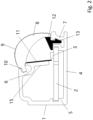
- is a schematic cross-sectional view of the lamp shown in the
Fig.1 perpendicular to the length direction; - Fig.3
- is a schematic cross-sectional view of a lamp for use in a display cabinet according to a second embodiment of the present invention;
- Fig.4
- is a schematic cross-sectional view of a lamp for use in a display cabinet according to a third embodiment of the present invention.
- The technical solutions of the present invention will be clearly and completely described below with reference to the accompanying drawings. Obviously, the described embodiments are a part of the embodiments of the present invention, and the present invention shall not be construed to be delimited to only these specific embodiments.
- As shown in
Figs. 1 and2 , a specific embodiment of the lamp for use in a display cabinet includes a bracket 1 configured to be arranged horizontally on the bottom plate of a display cabinet (not shown). In particular, the bracket 1 may include a more or less flat, planar surface for mounting on such a bottom plate of a display cabinet. The lamp further comprises acircuit board 2 and a lens structure arranged on the bracket 1, and a plurality of point-like light sources 3 arranged on thecircuit board 2 at intervals, preferably at equidistant intervals, along the length direction of thecircuit board 2. - The bracket 1 is integrally processed and preferably made of aluminum. The bracket 1 includes a
base 4 for fixing with the bottom plate of the display cabinet, asupport portion 5 for installing thecircuit board 2, and afirst installation portion 6 and asecond installation portion 7 for connecting with the two ends of the lens structure respectively. Thebase 4 preferably has a flat, planar surface, and is configured to match the bottom plate of the display cabinet. Thesupport portion 5 may be formed as an integrally formed boss or protrusion, and preferably includes a groove for accommodating an end surface of thecircuit board 2 for mounting. Thecircuit board 2 may be tightly accommodated in such a groove. Moreover, thefirst installation portion 6 and thesecond installation portion 7 are preferably grooves integrally formed with the bracket. More specifically, the first andsecond installation portion - The
circuit board 2 is a printed circuit board mounted on thesupport portion 5 of the bracket 1 Each point-likelight source 3 may be an LED chip. - The lens structure extends along the length direction of the
circuit board 2 and is disposed in the light output direction of the point-like light sources 3 and connected with the bracket 1 to cover a plurality of the point-like light sources 3, thereby reducing the lampshade setup and volume. The lens structure includes an integrally formedlight distribution lens 8 of an appropriate shape for light distribution and alens array 9 for extending two adjacent point-like light sources 3 to form a line-shaped light source. Specifically, thelight distribution lens 8 and thelens array 9 are both convex lenses, which are processed and formed by an extrusion process, particularly a plastic extrusion process. One end of thelight distribution lens 8 connected with the bracket 1 may be provided with a protrudingportion 10, and the protrudingportion 10 may be inserted in a form-fitting manner into thefirst installation portion 6 of the bracket 1 to be fixed at least in a direction in parallel with the light output direction. Thelens array 9 is arranged on the light exit surface of thelight distribution lens 8. As an alternative, thelens array 9 may also be arranged on the light entrance surface oflight distribution lens 8. - In order to improve the optical light efficiency of the lamp, reflection structures are arranged on each of the opposite sides of the lens structure along the length direction of the
circuit board 2, namely thefirst reflector 11 and thesecond reflector 12. As shown inFig. 2 , thefirst reflector 11 andsecond reflector 12 are each linear structure extending along the length direction of the bracket 1. As shown inFig. 2 , thefirst reflector 11, thesecond reflector 12 and the lens structure enclose an accommodating space for the plurality of the point-like light sources 3, which is more or less of triangular shape, if viewed in a cross-sectional view and extends along the length direction of the bracket 1. - More specifically, the
first reflector 11 is a diffuse reflector plate and thesecond reflector 12 is a non-transparent lens integrally formed with the lens structure, which may be accomplished e.g. by means of a two-color extrusion process. Preferably, the lens structure is a transparent part and thesecond reflector 12 is a white part. Most of the light emitted by the point-like light sources 3 is guided to the far end of the illuminated surface through thelight distribution lens 8. Thefirst reflector 11 and thesecond reflector 12 reflect a small portion of the light not received by thelight distribution lens 8 and then emit or guide this light portion towards and through thelight distribution lens 8 so that it is guided towards the near end of the illuminated surface. - As shown in
Fig. 2 , afirst plug portion 13 may be provided at an end of thesecond reflector 12, which is preferably formed of a plastic material and includes a resilient hook that extends into a groove provided at thesecond installation portion 7. More specifically, the first plug portion or its resilient hook may be snap-fitted into the groove shown inFig. 2 , and grips behind a corresponding protrusion formed in thesecond installation portion 7 of the bracket 1, so as to install and fix the lens structure with the bracket 1. - In order to prevent dust from entering the accommodating space, an
end cover 14 may be provided at each end of the bracket 1, and eachend cover 14 may be detachably connected to the bracket 1, e.g. by means of screws. - As shown in
Fig. 2 , the bracket 1 is provided with asupport plate 15 extending toward thecircuit board 2, and thesupport plate 15 is connected with thefirst installation portion 6 and is set at an angle without contacting thecircuit board 2. Thefirst reflector 11 is attached to thesupport plate 15, e.g. by means of an adhesive. The supportingplate 15 and the first reflectingplate 11 are inclined and extend towards the point-like light sources 3 to collect the light emitted by the point-like light sources 3 away from the irradiating surface as much as possible, and the reflected light is emitted through thelight distribution lens 8 to minimize the energy loss and improve the light efficiency. According to a further embodiment, thefirst reflector 11 may also be replaced by diffuse paper. - In the second embodiment as shown in
Fig. 3 , thefirst reflector 11 is integrally formed with the lens structure, and thefirst reflector 11 is provided with a connectingportion 16 connected with the bracket 1. The front end of the connecting portion may be formed as a resilient hook, configured to be snap-fitted into a groove of the first installation portion. Thereflection portion 17 extends toward the point-likelight source 3. The connectingportion 16 of thefirst reflector 11 is inserted into thefirst installation portion 6 of the bracket 1, more particularly into a groove disposed therein, to be fixed. The connectingportion 16 may approximately horizontally arranged, and thereflection portion 17 is arranged obliquely. - As to the third embodiment as shown in
Fig. 4 , the bracket 1 is provided with a plug-inboard 18 extending toward the convex lens structure, and one end of thefirst reflector 11 is provided with a second plug-inportion 18 which is fixed with the plug-inboard 18 in a form-fitting manner, and the other end abuts on thecircuit board 2. One end of thelight distribution lens 8 connected with the bracket 1 is provided with a protrudingportion 10, which is inserted into thefirst installation portion 6 of the bracket 1 and fixed, more specifically into a groove provided therein. - The present invention also provides a display cabinet, which includes the lamp used for the display cabinet, and the display cabinet is a vertical freezer, a refrigerator, and the like.
- The above are only preferred embodiments of the present invention, and are not used to limit the protection scope of the present invention.
Claims (11)
- A lamp for use in a display cabinet, comprising:a bracket (1) configured to be arranged on a bottom plate of the display cabinet;a circuit board (2) provided on the bracket (1);a plurality of point-like light sources (3) arranged on the circuit board (2) at intervals along the length direction of the circuit board (2);a lens structure (8) extending along the length direction of the circuit board (2) and disposed in the light output direction of the plurality of point-like light sources (3), whereinthe lens structure (8) is connected with the bracket (1) to cover the plurality of the point-like light sources (3) and comprises an integrally formed light distribution lens (8) and a lens array (9) for extending respective two adjacent point-like light sources (3) of the plurality of point-like light sources (3) to form a line light source; whereina first reflector (11) is provided on a first side of the lens structure (8) and second reflector (12) is provided on a second side of the lens structure (8) opposite to the first side, said first reflector (11) and said second reflector (12) each extending along the longitudinal direction, and whereinthe first reflector (11), the second reflector (12) and the lens structure (8) enclose an accommodating space accommodating the plurality of the point-like light sources (3);characterized in that the first reflector (11) is a diffuse reflector plate and the second reflector (12) is a non-transparent lens integrally formed with the lens structure (8).
- The lamp for use in a display cabinet as claimed in claim 1, wherein the light distribution lens (8) and the lens array (9) are both convex lenses.
- The lamp for use in a display cabinet as claimed in any of the preceding claims, wherein the lens structure (8) is a transparent part and the second reflector (12) is a white part.
- The lamp for use in a display cabinet as claimed in any of the preceding claims, wherein the bracket (1) is provided with a support plate (15) extending toward the circuit board (2), wherein the first reflector (11) is attached to or provided on the support plate (15).
- The lamp for use in a display cabinet as claimed in claim 4, wherein the support plate (15) is inclined at an acute angle relative to the circuit board (2) without contacting the circuit board (2) and extends towards the plurality of point-like light sources (3) so as to collect light emitted by the plurality of point-like light sources (3) and reflect the collected light towards the lens structure (8).
- The lamp for use in a display cabinet as claimed in any of the preceding claims, wherein the first reflector (11) is formed integrally with the lens structure (8), and wherein the first reflector (11) is provided with a connecting portion (16) configured to be connected with the bracket (1) and a reflection portion (17) extending toward the plurality of point-like light sources (3).
- The lamp for use in a display cabinet as claimed in claim 6, wherein a front end of the connecting portion (16) is formed as a resilient hook configured to be snap-fitted into a groove of a first installation portion (6) of the bracket (1).
- The lamp for use in a display cabinet as claimed in any of claims 1 to 5, wherein the bracket (1) is provided with a plug-in board (18) extending toward the lens structure (8), and wherein a first end of the first reflector (11) is provided with a second plug-in portion (19) configured to be fixed with the plug-in board (18) in a form-fitting manner and a second end of the first reflector (11) opposite to the first end of the first reflector (11) abuts on the circuit board (2).
- The lamp for use in a display cabinet as claimed in any of the preceding claims, further comprising end covers (14) provided at opposite ends of the bracket (1), for preventing dust from entering the accommodating space.
- The lamp for use in a display cabinet as claimed in claim 9, wherein each end cover (14) is detachably connected to the bracket (1).
- A display cabinet comprising at least one lamp for use in a display cabinet as claimed in any of the preceding claims.
Applications Claiming Priority (1)
| Application Number | Priority Date | Filing Date | Title |
|---|---|---|---|
| CN202122875691.8U CN216243826U (en) | 2021-11-22 | 2021-11-22 | Lamp for display cabinet and display cabinet |
Publications (2)
| Publication Number | Publication Date |
|---|---|
| EP4184053A1 EP4184053A1 (en) | 2023-05-24 |
| EP4184053B1 true EP4184053B1 (en) | 2025-01-29 |
Family
ID=80954640
Family Applications (1)
| Application Number | Title | Priority Date | Filing Date |
|---|---|---|---|
| EP22208115.0A Active EP4184053B1 (en) | 2021-11-22 | 2022-11-17 | Lamp for use in a display cabinet and display cabinet thereof |
Country Status (3)
| Country | Link |
|---|---|
| EP (1) | EP4184053B1 (en) |
| CN (1) | CN216243826U (en) |
| ES (1) | ES3014271T3 (en) |
Family Cites Families (5)
| Publication number | Priority date | Publication date | Assignee | Title |
|---|---|---|---|---|
| US5895111A (en) * | 1992-04-08 | 1999-04-20 | Anthony's Manufacturing Company, Inc. | Display case with lens lighting system |
| JP2009195273A (en) * | 2008-02-19 | 2009-09-03 | Sanyo Electric Co Ltd | Showcase |
| JP2011196674A (en) * | 2010-02-26 | 2011-10-06 | Panasonic Corp | Refrigerator |
| CN109973850A (en) * | 2019-04-19 | 2019-07-05 | 赛尔富电子有限公司 | A kind of linear light source headlamp |
| CN112432424A (en) * | 2019-08-07 | 2021-03-02 | 青岛海尔电冰箱有限公司 | Refrigerator lighting device and refrigerator |
-
2021
- 2021-11-22 CN CN202122875691.8U patent/CN216243826U/en active Active
-
2022
- 2022-11-17 EP EP22208115.0A patent/EP4184053B1/en active Active
- 2022-11-17 ES ES22208115T patent/ES3014271T3/en active Active
Also Published As
| Publication number | Publication date |
|---|---|
| CN216243826U (en) | 2022-04-08 |
| EP4184053A1 (en) | 2023-05-24 |
| ES3014271T3 (en) | 2025-04-21 |
Similar Documents
| Publication | Publication Date | Title |
|---|---|---|
| US11454370B2 (en) | Line source lighting system | |
| CN106439566B (en) | LED strip-shaped lamp | |
| CN101896764B (en) | Light Distribution Using LED Components | |
| KR100981012B1 (en) | Apparatus, method and items for optical waveguide and lamp assembly | |
| US20170370539A1 (en) | Led bar lighting and exhibition cabinet having same | |
| EP4031805B1 (en) | Lighting lamp | |
| US20200332980A1 (en) | Strip Light Fixture | |
| US11047536B2 (en) | Tubular LED fixture | |
| KR101733697B1 (en) | Flat-type led illumination device | |
| CN210605060U (en) | Light guide structure and lamp | |
| US6966686B2 (en) | Surface light source device | |
| KR101139655B1 (en) | Frame of LED Fluorescent Lamp | |
| EP4184053A1 (en) | Lamp for use in a display cabinet and display cabinet thereof | |
| CN102168814B (en) | Lighting device | |
| CN222085834U (en) | Lamp set | |
| KR100736670B1 (en) | High Efficiency LED Backlight Unit | |
| US10874227B1 (en) | Strip light used in showcase | |
| US20230408068A1 (en) | Light source module and lighting apparatus | |
| CN215001131U (en) | Panel light and household electrical appliances | |
| EP3726126B1 (en) | Tubular led light fixture | |
| CN213983037U (en) | LED panel light | |
| CN113674649B (en) | Backlight module and display device | |
| CN210568190U (en) | Illumination device and light collecting column system | |
| KR102182715B1 (en) | Plate type led illuminator | |
| CN223178708U (en) | Wall washing track lamp |
Legal Events
| Date | Code | Title | Description |
|---|---|---|---|
| PUAI | Public reference made under article 153(3) epc to a published international application that has entered the european phase |
Free format text: ORIGINAL CODE: 0009012 |
|
| STAA | Information on the status of an ep patent application or granted ep patent |
Free format text: STATUS: THE APPLICATION HAS BEEN PUBLISHED |
|
| AK | Designated contracting states |
Kind code of ref document: A1 Designated state(s): AL AT BE BG CH CY CZ DE DK EE ES FI FR GB GR HR HU IE IS IT LI LT LU LV MC ME MK MT NL NO PL PT RO RS SE SI SK SM TR |
|
| STAA | Information on the status of an ep patent application or granted ep patent |
Free format text: STATUS: REQUEST FOR EXAMINATION WAS MADE |
|
| 17P | Request for examination filed |
Effective date: 20230630 |
|
| RBV | Designated contracting states (corrected) |
Designated state(s): AL AT BE BG CH CY CZ DE DK EE ES FI FR GB GR HR HU IE IS IT LI LT LU LV MC ME MK MT NL NO PL PT RO RS SE SI SK SM TR |
|
| GRAP | Despatch of communication of intention to grant a patent |
Free format text: ORIGINAL CODE: EPIDOSNIGR1 |
|
| STAA | Information on the status of an ep patent application or granted ep patent |
Free format text: STATUS: GRANT OF PATENT IS INTENDED |
|
| RIC1 | Information provided on ipc code assigned before grant |
Ipc: F21Y 115/10 20160101ALN20241105BHEP Ipc: F21Y 103/10 20160101ALN20241105BHEP Ipc: F21W 131/305 20060101ALN20241105BHEP Ipc: F21V 17/16 20060101ALN20241105BHEP Ipc: F21V 7/05 20060101ALN20241105BHEP Ipc: F21V 13/04 20060101ALI20241105BHEP Ipc: F21V 7/00 20060101ALI20241105BHEP Ipc: F21V 5/00 20180101ALI20241105BHEP Ipc: F21S 4/28 20160101AFI20241105BHEP |
|
| GRAS | Grant fee paid |
Free format text: ORIGINAL CODE: EPIDOSNIGR3 |
|
| INTG | Intention to grant announced |
Effective date: 20241122 |
|
| GRAA | (expected) grant |
Free format text: ORIGINAL CODE: 0009210 |
|
| STAA | Information on the status of an ep patent application or granted ep patent |
Free format text: STATUS: THE PATENT HAS BEEN GRANTED |
|
| AK | Designated contracting states |
Kind code of ref document: B1 Designated state(s): AL AT BE BG CH CY CZ DE DK EE ES FI FR GB GR HR HU IE IS IT LI LT LU LV MC ME MK MT NL NO PL PT RO RS SE SI SK SM TR |
|
| REG | Reference to a national code |
Ref country code: GB Ref legal event code: FG4D |
|
| REG | Reference to a national code |
Ref country code: CH Ref legal event code: EP |
|
| REG | Reference to a national code |
Ref country code: DE Ref legal event code: R096 Ref document number: 602022010069 Country of ref document: DE |
|
| REG | Reference to a national code |
Ref country code: IE Ref legal event code: FG4D |
|
| REG | Reference to a national code |
Ref country code: ES Ref legal event code: FG2A Ref document number: 3014271 Country of ref document: ES Kind code of ref document: T3 Effective date: 20250421 |
|
| REG | Reference to a national code |
Ref country code: NL Ref legal event code: MP Effective date: 20250129 |
|
| PG25 | Lapsed in a contracting state [announced via postgrant information from national office to epo] |
Ref country code: NL Free format text: LAPSE BECAUSE OF FAILURE TO SUBMIT A TRANSLATION OF THE DESCRIPTION OR TO PAY THE FEE WITHIN THE PRESCRIBED TIME-LIMIT Effective date: 20250129 |
|
| PG25 | Lapsed in a contracting state [announced via postgrant information from national office to epo] |
Ref country code: RS Free format text: LAPSE BECAUSE OF FAILURE TO SUBMIT A TRANSLATION OF THE DESCRIPTION OR TO PAY THE FEE WITHIN THE PRESCRIBED TIME-LIMIT Effective date: 20250429 |
|
| PG25 | Lapsed in a contracting state [announced via postgrant information from national office to epo] |
Ref country code: FI Free format text: LAPSE BECAUSE OF FAILURE TO SUBMIT A TRANSLATION OF THE DESCRIPTION OR TO PAY THE FEE WITHIN THE PRESCRIBED TIME-LIMIT Effective date: 20250129 |
|
| PG25 | Lapsed in a contracting state [announced via postgrant information from national office to epo] |
Ref country code: PL Free format text: LAPSE BECAUSE OF FAILURE TO SUBMIT A TRANSLATION OF THE DESCRIPTION OR TO PAY THE FEE WITHIN THE PRESCRIBED TIME-LIMIT Effective date: 20250129 |
|
| REG | Reference to a national code |
Ref country code: LT Ref legal event code: MG9D |
|
| PG25 | Lapsed in a contracting state [announced via postgrant information from national office to epo] |
Ref country code: IS Free format text: LAPSE BECAUSE OF FAILURE TO SUBMIT A TRANSLATION OF THE DESCRIPTION OR TO PAY THE FEE WITHIN THE PRESCRIBED TIME-LIMIT Effective date: 20250529 Ref country code: NO Free format text: LAPSE BECAUSE OF FAILURE TO SUBMIT A TRANSLATION OF THE DESCRIPTION OR TO PAY THE FEE WITHIN THE PRESCRIBED TIME-LIMIT Effective date: 20250429 |
|
| REG | Reference to a national code |
Ref country code: AT Ref legal event code: MK05 Ref document number: 1763766 Country of ref document: AT Kind code of ref document: T Effective date: 20250129 |
|
| PG25 | Lapsed in a contracting state [announced via postgrant information from national office to epo] |
Ref country code: HR Free format text: LAPSE BECAUSE OF FAILURE TO SUBMIT A TRANSLATION OF THE DESCRIPTION OR TO PAY THE FEE WITHIN THE PRESCRIBED TIME-LIMIT Effective date: 20250129 |
|
| PG25 | Lapsed in a contracting state [announced via postgrant information from national office to epo] |
Ref country code: LV Free format text: LAPSE BECAUSE OF FAILURE TO SUBMIT A TRANSLATION OF THE DESCRIPTION OR TO PAY THE FEE WITHIN THE PRESCRIBED TIME-LIMIT Effective date: 20250129 Ref country code: PT Free format text: LAPSE BECAUSE OF FAILURE TO SUBMIT A TRANSLATION OF THE DESCRIPTION OR TO PAY THE FEE WITHIN THE PRESCRIBED TIME-LIMIT Effective date: 20250529 |
|
| PG25 | Lapsed in a contracting state [announced via postgrant information from national office to epo] |
Ref country code: GR Free format text: LAPSE BECAUSE OF FAILURE TO SUBMIT A TRANSLATION OF THE DESCRIPTION OR TO PAY THE FEE WITHIN THE PRESCRIBED TIME-LIMIT Effective date: 20250430 Ref country code: BG Free format text: LAPSE BECAUSE OF FAILURE TO SUBMIT A TRANSLATION OF THE DESCRIPTION OR TO PAY THE FEE WITHIN THE PRESCRIBED TIME-LIMIT Effective date: 20250129 |
|
| PG25 | Lapsed in a contracting state [announced via postgrant information from national office to epo] |
Ref country code: AT Free format text: LAPSE BECAUSE OF FAILURE TO SUBMIT A TRANSLATION OF THE DESCRIPTION OR TO PAY THE FEE WITHIN THE PRESCRIBED TIME-LIMIT Effective date: 20250129 |
|
| PG25 | Lapsed in a contracting state [announced via postgrant information from national office to epo] |
Ref country code: SE Free format text: LAPSE BECAUSE OF FAILURE TO SUBMIT A TRANSLATION OF THE DESCRIPTION OR TO PAY THE FEE WITHIN THE PRESCRIBED TIME-LIMIT Effective date: 20250129 |
|
| PG25 | Lapsed in a contracting state [announced via postgrant information from national office to epo] |
Ref country code: SM Free format text: LAPSE BECAUSE OF FAILURE TO SUBMIT A TRANSLATION OF THE DESCRIPTION OR TO PAY THE FEE WITHIN THE PRESCRIBED TIME-LIMIT Effective date: 20250129 |
|
| PG25 | Lapsed in a contracting state [announced via postgrant information from national office to epo] |
Ref country code: DK Free format text: LAPSE BECAUSE OF FAILURE TO SUBMIT A TRANSLATION OF THE DESCRIPTION OR TO PAY THE FEE WITHIN THE PRESCRIBED TIME-LIMIT Effective date: 20250129 |
|
| PG25 | Lapsed in a contracting state [announced via postgrant information from national office to epo] |
Ref country code: CZ Free format text: LAPSE BECAUSE OF FAILURE TO SUBMIT A TRANSLATION OF THE DESCRIPTION OR TO PAY THE FEE WITHIN THE PRESCRIBED TIME-LIMIT Effective date: 20250129 Ref country code: EE Free format text: LAPSE BECAUSE OF FAILURE TO SUBMIT A TRANSLATION OF THE DESCRIPTION OR TO PAY THE FEE WITHIN THE PRESCRIBED TIME-LIMIT Effective date: 20250129 |
|
| PG25 | Lapsed in a contracting state [announced via postgrant information from national office to epo] |
Ref country code: RO Free format text: LAPSE BECAUSE OF FAILURE TO SUBMIT A TRANSLATION OF THE DESCRIPTION OR TO PAY THE FEE WITHIN THE PRESCRIBED TIME-LIMIT Effective date: 20250129 |
|
| PG25 | Lapsed in a contracting state [announced via postgrant information from national office to epo] |
Ref country code: SK Free format text: LAPSE BECAUSE OF FAILURE TO SUBMIT A TRANSLATION OF THE DESCRIPTION OR TO PAY THE FEE WITHIN THE PRESCRIBED TIME-LIMIT Effective date: 20250129 |
|
| REG | Reference to a national code |
Ref country code: DE Ref legal event code: R097 Ref document number: 602022010069 Country of ref document: DE |
|
| PLBE | No opposition filed within time limit |
Free format text: ORIGINAL CODE: 0009261 |
|
| STAA | Information on the status of an ep patent application or granted ep patent |
Free format text: STATUS: NO OPPOSITION FILED WITHIN TIME LIMIT |
|
| 26N | No opposition filed |
Effective date: 20251030 |
|
| PGFP | Annual fee paid to national office [announced via postgrant information from national office to epo] |
Ref country code: DE Payment date: 20251128 Year of fee payment: 4 |
|
| PGFP | Annual fee paid to national office [announced via postgrant information from national office to epo] |
Ref country code: IT Payment date: 20251201 Year of fee payment: 4 |
|
| PGFP | Annual fee paid to national office [announced via postgrant information from national office to epo] |
Ref country code: ES Payment date: 20251216 Year of fee payment: 4 |