EP4183991A1 - Turbocharger waste gate poppet valve connected to rotary valve shaft by arm and retaining ring - Google Patents
Turbocharger waste gate poppet valve connected to rotary valve shaft by arm and retaining ring Download PDFInfo
- Publication number
- EP4183991A1 EP4183991A1 EP22194560.3A EP22194560A EP4183991A1 EP 4183991 A1 EP4183991 A1 EP 4183991A1 EP 22194560 A EP22194560 A EP 22194560A EP 4183991 A1 EP4183991 A1 EP 4183991A1
- Authority
- EP
- European Patent Office
- Prior art keywords
- arm
- pin
- poppet
- retaining ring
- groove
- Prior art date
- Legal status (The legal status is an assumption and is not a legal conclusion. Google has not performed a legal analysis and makes no representation as to the accuracy of the status listed.)
- Granted
Links
Images





Classifications
-
- F—MECHANICAL ENGINEERING; LIGHTING; HEATING; WEAPONS; BLASTING
- F02—COMBUSTION ENGINES; HOT-GAS OR COMBUSTION-PRODUCT ENGINE PLANTS
- F02B—INTERNAL-COMBUSTION PISTON ENGINES; COMBUSTION ENGINES IN GENERAL
- F02B37/00—Engines characterised by provision of pumps driven at least for part of the time by exhaust
- F02B37/12—Control of the pumps
- F02B37/18—Control of the pumps by bypassing exhaust from the inlet to the outlet of turbine or to the atmosphere
- F02B37/183—Arrangements of bypass valves or actuators therefor
- F02B37/186—Arrangements of actuators or linkage for bypass valves
-
- F—MECHANICAL ENGINEERING; LIGHTING; HEATING; WEAPONS; BLASTING
- F04—POSITIVE - DISPLACEMENT MACHINES FOR LIQUIDS; PUMPS FOR LIQUIDS OR ELASTIC FLUIDS
- F04D—NON-POSITIVE-DISPLACEMENT PUMPS
- F04D27/00—Control, e.g. regulation, of pumps, pumping installations or pumping systems specially adapted for elastic fluids
- F04D27/02—Surge control
- F04D27/0207—Surge control by bleeding, bypassing or recycling fluids
- F04D27/0215—Arrangements therefor, e.g. bleed or by-pass valves
-
- F—MECHANICAL ENGINEERING; LIGHTING; HEATING; WEAPONS; BLASTING
- F01—MACHINES OR ENGINES IN GENERAL; ENGINE PLANTS IN GENERAL; STEAM ENGINES
- F01D—NON-POSITIVE DISPLACEMENT MACHINES OR ENGINES, e.g. STEAM TURBINES
- F01D17/00—Regulating or controlling by varying flow
- F01D17/10—Final actuators
- F01D17/105—Final actuators by passing part of the fluid
-
- F—MECHANICAL ENGINEERING; LIGHTING; HEATING; WEAPONS; BLASTING
- F02—COMBUSTION ENGINES; HOT-GAS OR COMBUSTION-PRODUCT ENGINE PLANTS
- F02B—INTERNAL-COMBUSTION PISTON ENGINES; COMBUSTION ENGINES IN GENERAL
- F02B37/00—Engines characterised by provision of pumps driven at least for part of the time by exhaust
- F02B37/12—Control of the pumps
- F02B37/18—Control of the pumps by bypassing exhaust from the inlet to the outlet of turbine or to the atmosphere
-
- F—MECHANICAL ENGINEERING; LIGHTING; HEATING; WEAPONS; BLASTING
- F04—POSITIVE - DISPLACEMENT MACHINES FOR LIQUIDS; PUMPS FOR LIQUIDS OR ELASTIC FLUIDS
- F04D—NON-POSITIVE-DISPLACEMENT PUMPS
- F04D17/00—Radial-flow pumps, e.g. centrifugal pumps; Helico-centrifugal pumps
- F04D17/08—Centrifugal pumps
- F04D17/10—Centrifugal pumps for compressing or evacuating
-
- F—MECHANICAL ENGINEERING; LIGHTING; HEATING; WEAPONS; BLASTING
- F16—ENGINEERING ELEMENTS AND UNITS; GENERAL MEASURES FOR PRODUCING AND MAINTAINING EFFECTIVE FUNCTIONING OF MACHINES OR INSTALLATIONS; THERMAL INSULATION IN GENERAL
- F16K—VALVES; TAPS; COCKS; ACTUATING-FLOATS; DEVICES FOR VENTING OR AERATING
- F16K1/00—Lift valves or globe valves, i.e. cut-off apparatus with closure members having at least a component of their opening and closing motion perpendicular to the closing faces
- F16K1/16—Lift valves or globe valves, i.e. cut-off apparatus with closure members having at least a component of their opening and closing motion perpendicular to the closing faces with pivoted closure-members
- F16K1/18—Lift valves or globe valves, i.e. cut-off apparatus with closure members having at least a component of their opening and closing motion perpendicular to the closing faces with pivoted closure-members with pivoted discs or flaps
- F16K1/20—Lift valves or globe valves, i.e. cut-off apparatus with closure members having at least a component of their opening and closing motion perpendicular to the closing faces with pivoted closure-members with pivoted discs or flaps with axis of rotation arranged externally of valve member
-
- F—MECHANICAL ENGINEERING; LIGHTING; HEATING; WEAPONS; BLASTING
- F16—ENGINEERING ELEMENTS AND UNITS; GENERAL MEASURES FOR PRODUCING AND MAINTAINING EFFECTIVE FUNCTIONING OF MACHINES OR INSTALLATIONS; THERMAL INSULATION IN GENERAL
- F16K—VALVES; TAPS; COCKS; ACTUATING-FLOATS; DEVICES FOR VENTING OR AERATING
- F16K1/00—Lift valves or globe valves, i.e. cut-off apparatus with closure members having at least a component of their opening and closing motion perpendicular to the closing faces
- F16K1/32—Details
- F16K1/48—Attaching valve members to screw-spindles
-
- F—MECHANICAL ENGINEERING; LIGHTING; HEATING; WEAPONS; BLASTING
- F16—ENGINEERING ELEMENTS AND UNITS; GENERAL MEASURES FOR PRODUCING AND MAINTAINING EFFECTIVE FUNCTIONING OF MACHINES OR INSTALLATIONS; THERMAL INSULATION IN GENERAL
- F16K—VALVES; TAPS; COCKS; ACTUATING-FLOATS; DEVICES FOR VENTING OR AERATING
- F16K31/00—Actuating devices; Operating means; Releasing devices
- F16K31/44—Mechanical actuating means
- F16K31/52—Mechanical actuating means with crank, eccentric, or cam
- F16K31/521—Mechanical actuating means with crank, eccentric, or cam comprising a pivoted disc or flap
-
- F—MECHANICAL ENGINEERING; LIGHTING; HEATING; WEAPONS; BLASTING
- F05—INDEXING SCHEMES RELATING TO ENGINES OR PUMPS IN VARIOUS SUBCLASSES OF CLASSES F01-F04
- F05D—INDEXING SCHEME FOR ASPECTS RELATING TO NON-POSITIVE-DISPLACEMENT MACHINES OR ENGINES, GAS-TURBINES OR JET-PROPULSION PLANTS
- F05D2220/00—Application
- F05D2220/40—Application in turbochargers
-
- F—MECHANICAL ENGINEERING; LIGHTING; HEATING; WEAPONS; BLASTING
- F05—INDEXING SCHEMES RELATING TO ENGINES OR PUMPS IN VARIOUS SUBCLASSES OF CLASSES F01-F04
- F05D—INDEXING SCHEME FOR ASPECTS RELATING TO NON-POSITIVE-DISPLACEMENT MACHINES OR ENGINES, GAS-TURBINES OR JET-PROPULSION PLANTS
- F05D2250/00—Geometry
- F05D2250/10—Two-dimensional
- F05D2250/13—Two-dimensional trapezoidal
- F05D2250/131—Two-dimensional trapezoidal polygonal
-
- F—MECHANICAL ENGINEERING; LIGHTING; HEATING; WEAPONS; BLASTING
- F05—INDEXING SCHEMES RELATING TO ENGINES OR PUMPS IN VARIOUS SUBCLASSES OF CLASSES F01-F04
- F05D—INDEXING SCHEME FOR ASPECTS RELATING TO NON-POSITIVE-DISPLACEMENT MACHINES OR ENGINES, GAS-TURBINES OR JET-PROPULSION PLANTS
- F05D2260/00—Function
- F05D2260/50—Kinematic linkage, i.e. transmission of position
-
- Y—GENERAL TAGGING OF NEW TECHNOLOGICAL DEVELOPMENTS; GENERAL TAGGING OF CROSS-SECTIONAL TECHNOLOGIES SPANNING OVER SEVERAL SECTIONS OF THE IPC; TECHNICAL SUBJECTS COVERED BY FORMER USPC CROSS-REFERENCE ART COLLECTIONS [XRACs] AND DIGESTS
- Y02—TECHNOLOGIES OR APPLICATIONS FOR MITIGATION OR ADAPTATION AGAINST CLIMATE CHANGE
- Y02T—CLIMATE CHANGE MITIGATION TECHNOLOGIES RELATED TO TRANSPORTATION
- Y02T10/00—Road transport of goods or passengers
- Y02T10/10—Internal combustion engine [ICE] based vehicles
- Y02T10/12—Improving ICE efficiencies
Definitions
- This application relates generally to turbochargers for internal combustion engines, and relates more particularly to a crank and linkage assembly for connecting between an actuator and an adjustable component such as a waste gate valve or the like.
- An exhaust gas-driven turbocharger is a device used in conjunction with an internal combustion engine for increasing the power output of the engine by compressing the air that is delivered to the air intake of the engine to be mixed with fuel and burned in the engine.
- a turbocharger comprises a compressor wheel mounted on one end of a shaft in a compressor housing and a turbine wheel mounted on the other end of the shaft in a turbine housing.
- the turbine housing defines a generally annular chamber that surrounds the turbine wheel and that receives exhaust gas from an engine.
- the turbine assembly includes a nozzle that leads from the chamber into the turbine wheel.
- the exhaust gas flows from the chamber through the nozzle to the turbine wheel and the turbine wheel is driven by the exhaust gas, which is then discharged into an exhaust conduit that may be connected to further treatment devices such as a catalytic device and/or sound-attenuating muffler.
- the turbine thus extracts power from the exhaust gas and drives the compressor.
- the compressor receives ambient air through an inlet of the compressor housing and the air is compressed by the compressor wheel and is then discharged from the housing to the engine air intake.
- the turbine of the turbocharger typically includes a valve (often called a waste gate valve) arranged in the turbine housing in a location such that opening the valve causes the majority of exhaust gases coming from the engine to bypass the turbine wheel and proceed directly into the exhaust conduit.
- the waste gate valve enables the power-extraction of the turbine to be controlled, thereby controlling the amount of boost provided by the compressor.
- the waste gate valve can be either closed, partially opened to various degrees, or fully open, depending upon the operating condition of the engine and the amount of boost desired from the turbocharger.
- the waste gate valve is typically actuated by a rotary actuator whose output shaft is connected to a crank.
- the actuator crank is rotatably coupled to one end of a linkage, and the opposite end of the linkage is rotatably coupled to a crank affixed to the valve shaft of the waste gate valve.
- An arm on the distal end of the valve shaft is connected to the poppet of the valve, typically by a pin projecting from the poppet and received through a bore in the arm.
- a disc washer is riveted to a distal end of the pin, with a spring washer disposed between the disc washer and the arm.
- the present disclosure describes a waste gate assembly for a turbocharger that can mitigate or eliminate the drawbacks noted above, and achieve further advantages noted herein.
- the disclosed assembly can simplify the assembly process by facilitating a push-to-connect process between the valve member arm and the pin of the poppet.
- a waste gate assembly comprises:
- the retaining ring not only effects a connection between the arm and the poppet in a simple and repeatable fashion, but the retaining ring also provides a biasing force on the poppet (i.e., a pre-load force) urging the poppet away from the arm and toward the valve seat when the valve is closed. Additionally, the retaining ring allows a small amount of movement of the poppet relative to the arm in the direction of the through-bore's axis. These characteristics allow the poppet to form a secure seal against the valve seat.
- the anti-rotation feature in one embodiment is formed by shape-locking between the pin having a non-round cross-sectional shape and the through bore in the arm having a corresponding non-round cross-sectional shape.
- the anti-rotation feature comprises a recess defined in the arm and a projection or key formed on the poppet, the key being received into the recess to prevent rotation of the poppet.
- the two ends of the retaining ring extend into the recess defined in the arm.
- the arm defines a slot extending from an outer surface of the arm to the through bore, and the two ends of the retaining ring extend through the slot.
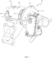
- FIG. 1 illustrates a turbocharger 10 in accordance with an embodiment of the invention.
- the turbocharger comprises a compressor 12 having a compressor wheel (not visible) mounted within a compressor housing 16 defining an air inlet 17 for the compressor, and a turbine 22 comprising a turbine wheel 25 ( FIG. 3 ) mounted within a turbine housing 24 and connected to a shaft (not visible) that also connects with the compressor wheel.
- a center housing 20 is disposed between and secured to the compressor housing and turbine housing, and contains bearings for the shaft.
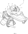
- the turbine housing 24 defines an annular chamber surrounding the turbine wheel 25 for receiving exhaust gas from an internal combustion engine (not shown). Exhaust gas is directed from the chamber via a turbine nozzle onto the turbine wheel. In some operating conditions, it is desirable to cause some of the exhaust gas to bypass the turbine wheel and proceed directly into the downstream exhaust conduit, and to this end, turbochargers typically include a waste gate valve 30 ( FIGS. 2-4 ) arranged for opening and closing a bypass passage 29 ( FIG. 3 ) defined by the turbine housing.
- the bypass passage connects between the exhaust gas chamber and the discharge bore of the turbine housing downstream of the turbine wheel. Thus, when the waste gate valve is opened, some of the exhaust gas passes through the valve and thereby bypasses the turbine wheel.
- regulation of the waste gate valve is accomplished by an actuator 40 connected to the valve via a kinematic linkage arrangement comprising a first crank C1, a linkage L, and a second crank C2.
- the valve 30 has a rotary valve shaft 32, and one end of the first crank C1 is rigidly affixed to the valve shaft.
- the actuator 40 has a rotary output shaft 42, and one end of the second crank C2 is rigidly affixed to the output shaft.
- a first end of the linkage L is rotatably coupled to the first crank C1, and the opposite second end of the linkage is rotatably coupled to the second crank C2. Accordingly, rotation of the actuator shaft 42 causes two cranks and the linkage to impart rotation to the valve shaft 32.
- the turbine housing defines a bearing hole 27 in which a bushing 23 is installed, and the valve shaft 32 of the waste gate valve extends through the bushing, which allows the shaft to rotate about its axis and thereby cause the valve to open or close the bypass passage 29.
- the turbine housing defines valve seat 21 the surrounds the open end of the bypass passage.
- the waste gate valve includes a poppet 38 having a disc shape and being sized and configured to abut the valve seat 21 so that the poppet closes the bypass passage.
- the poppet includes an integral pin P projecting from the center of the poppet normal to the plane of the disc.
- the pin is received into a through bore 35 formed at a distal end of an arm 34 that is affixed to the end of the valve shaft 32, the arm extending at an oblique angle to the valve shaft axis.
- the connection of the pin to the arm is accomplished by a retaining ring 40 in a manner described below.
- the retaining ring 40 is formed from elastically deformable wire by any suitable process such as a rolling process as commonly used for rolling springs and the like, so that the retaining ring has a generally polygonal shape that is non-closed, i.e., a gap remains between the opposite ends of the wire.
- the ring is formed to have a plurality of vertices V and a plurality of sides S each of which extends between two of said vertices.
- the retaining ring is generally U-shaped, having two vertices V and three sides S.
- vertex and verices do not require or imply that they must be sharp corners, which in practice would be impossible, it always being necessary to have a non-zero radius of curvature of the wire at each vertex.
- side does not require or imply that the sides must be linear, although linear sides can be used as shown in the drawings.
- the arm 34 defines a through bore 35.
- the inner surface of the bore defines an arm groove AG at least partially encircling the central axis of the bore.
- the radial depth and the axial length of the arm groove are sized in relation to the diameter of the wire so that portions of the wire can be received into the arm groove.
- the retaining ring 40 is pre-installed in the arm 34 as shown in FIG. 10 , prior to connection to the pin of the poppet.
- the arm includes a slot 36 that extends from an outer face of the arm into the through bore 35. The retaining ring is pushed through this slot until the vertices of the retaining ring are seated into the arm groove.
- the two ends of the retaining ring wire are flared away from each other with a spacing that exceeds the width of the slot 36.
- the two ends of the wire project out from the slot and are compressed toward each other by the side walls of the slot (compare FIGS. 8 and 9A ).
- the through bore 35 in the arm 34 of the valve member is non-round.
- the shape of the bore comprises a circle with a flat on one side.
- the pin P on the poppet 38 correspondingly has a non-round cross-sectional shape consisting of a circle with a flat F on one side, complementing the non-round bore 35 in the arm. Accordingly, shape-locking occurs between these complementary shapes such that the poppet is prevented from rotating about the pin axis relative to the arm, thus comprising a non-rotation feature for the valve arrangement.
- FIGS. 11-14 a push-to-connect process for connecting the poppet to the arm of the valve member is described.
- a portion of the arm 34 has been removed so that the retaining ring 40 can be seen.
- FIG. 11 shows the unconnected assembly prior to the push-to-connect process.
- the pin P of the poppet 38 extends along a pin axis and terminates at a distal end.
- the generally cylindrical outer surface of the pin defines a pin groove PG therein.
- the radial depth and axial length of the pin groove are selected in relation to the diameter of the wire forming the retaining ring 40.
- the pin defines a tapered end TE.
- connection of the arm 34 having the pre-installed retaining ring 40 to the pin of the poppet is a simple push-to-connect process in which the tapered end of the pin contacts and urges the retaining ring to radially expand. More particularly, it is the sides S of the ring that are resiliently deformed radially outwardly (see FIGS. 12 and 13 ).
- the retaining ring allows a small amount of movement of the poppet 38 relative to the arm 34 along the axial direction of the through-bore 35. Furthermore, when the retaining ring has a non-planar free shape (as in the embodiments of FIGS. 21 and 22 , for example), it also exerts a biasing force on the poppet tending to urge the poppet against the valve seat when the valve is closed.
- FIGS. 15-20 illustrate a second embodiment of the invention in which the retaining ring 40' has a different configuration and the anti-rotation feature also differs from that of the first embodiment.
- the modified arm 34' has a through bore 35' that is generally circular but connects with a further recess R in the arm to form a keyhole shape.
- the poppet 38' includes a key K comprising a short post or projection on one side of and extending parallel to the pin P'. When the poppet is connected to the arm 34', the key fits into the bottom side of the recess R and thereby prevents the poppet from rotating about the pin.
- the retaining ring 40' ( FIG. 15A ) is generally Omega-shaped, having four vertices V and three sides S.
- FIG. 16 shows the retaining ring pre-installed in the arm groove AG of the arm 34' (and in that state is relaxed or only slightly compressed radially inwardly by the outer wall of the groove).
- the two ends of the wire extend into the recess R.
- the retaining ring 40' functions substantially like the retaining ring 40 of the first embodiment.
- the tapered end TE of the pin expands the sides of the retaining ring radially outwardly as the arm is pushed onto the pin ( FIGS. 18 and 19 ), and once the arm groove AG becomes aligned with the pin groove PG, the sides return toward their original configuration and the ring's vertices V are engaged in the arm groove while the sides S are engaged in the pin groove ( FIG. 20 ).
- FIGS. 21A through 21C depict an alternative embodiment of retaining ring 140 that is generally U-shaped and non-planar.
- FIGS. 22A through 22C illustrate yet another embodiment of retaining ring 240 that is generally Omega-shaped and non-planar. Other configurations (rectangular, triangular, pentagonal, etc.) may also be used. While the illustrated retaining rings have the two ends of the wire flared outwardly away from each other, it is also possible for the two ends to extend toward each other, or to be parallel to each other.
Landscapes
- Engineering & Computer Science (AREA)
- General Engineering & Computer Science (AREA)
- Mechanical Engineering (AREA)
- Chemical & Material Sciences (AREA)
- Combustion & Propulsion (AREA)
- Life Sciences & Earth Sciences (AREA)
- Sustainable Development (AREA)
- Supercharger (AREA)
Abstract
Description
- This application relates generally to turbochargers for internal combustion engines, and relates more particularly to a crank and linkage assembly for connecting between an actuator and an adjustable component such as a waste gate valve or the like.
- An exhaust gas-driven turbocharger is a device used in conjunction with an internal combustion engine for increasing the power output of the engine by compressing the air that is delivered to the air intake of the engine to be mixed with fuel and burned in the engine. A turbocharger comprises a compressor wheel mounted on one end of a shaft in a compressor housing and a turbine wheel mounted on the other end of the shaft in a turbine housing. The turbine housing defines a generally annular chamber that surrounds the turbine wheel and that receives exhaust gas from an engine. The turbine assembly includes a nozzle that leads from the chamber into the turbine wheel. The exhaust gas flows from the chamber through the nozzle to the turbine wheel and the turbine wheel is driven by the exhaust gas, which is then discharged into an exhaust conduit that may be connected to further treatment devices such as a catalytic device and/or sound-attenuating muffler. The turbine thus extracts power from the exhaust gas and drives the compressor. The compressor receives ambient air through an inlet of the compressor housing and the air is compressed by the compressor wheel and is then discharged from the housing to the engine air intake.
- The turbine of the turbocharger typically includes a valve (often called a waste gate valve) arranged in the turbine housing in a location such that opening the valve causes the majority of exhaust gases coming from the engine to bypass the turbine wheel and proceed directly into the exhaust conduit. The waste gate valve enables the power-extraction of the turbine to be controlled, thereby controlling the amount of boost provided by the compressor. Thus, the waste gate valve can be either closed, partially opened to various degrees, or fully open, depending upon the operating condition of the engine and the amount of boost desired from the turbocharger.
- The waste gate valve is typically actuated by a rotary actuator whose output shaft is connected to a crank. The actuator crank is rotatably coupled to one end of a linkage, and the opposite end of the linkage is rotatably coupled to a crank affixed to the valve shaft of the waste gate valve. An arm on the distal end of the valve shaft is connected to the poppet of the valve, typically by a pin projecting from the poppet and received through a bore in the arm. A disc washer is riveted to a distal end of the pin, with a spring washer disposed between the disc washer and the arm. There are drawbacks to this conventional linkage assembly, such as the difficulty of controlling the quality of the connection between the poppet and the arm.
- The present disclosure describes a waste gate assembly for a turbocharger that can mitigate or eliminate the drawbacks noted above, and achieve further advantages noted herein. In particular, the disclosed assembly can simplify the assembly process by facilitating a push-to-connect process between the valve member arm and the pin of the poppet.
- In accordance with one embodiment disclosed herein, a waste gate assembly comprises:
- a valve member comprising a poppet having a pin extending therefrom along a pin axis and terminating at a distal end of the pin, an outer surface of the pin defining a pin groove therein at least partially encircling the pin axis, the pin groove being spaced along the pin axis from the poppet;
- a valve shaft extending along a shaft axis;
- an arm affixed to one end of the valve shaft and extending therefrom at an oblique angle relative to the shaft axis and terminating at a distal end, the distal end defining a through bore adjacent the distal end, an inner surface of the through bore defining an arm groove therein, a lengthwise portion of the pin being disposed within the through bore of the arm such that the arm groove is aligned with the pin groove; and
- a retaining ring comprising an elastically deformable wire formed into a generally polygonal non-closed configuration such that the retaining ring defines a plurality of vertices and a plurality of sides and two ends, wherein each of said plurality of vertices is within the arm groove and at least two of the plurality of sides has a portion engaged in the pin groove, thereby restraining movement of the arm along the pin axis, and further comprising an anti-rotation feature preventing rotational movement of the poppet relative to the arm about the pin axis, whereby rotation of the valve shaft about the shaft axis causes the arm to move the poppet along an arc about the valve axis.
- The retaining ring not only effects a connection between the arm and the poppet in a simple and repeatable fashion, but the retaining ring also provides a biasing force on the poppet (i.e., a pre-load force) urging the poppet away from the arm and toward the valve seat when the valve is closed. Additionally, the retaining ring allows a small amount of movement of the poppet relative to the arm in the direction of the through-bore's axis. These characteristics allow the poppet to form a secure seal against the valve seat.
- The anti-rotation feature in one embodiment is formed by shape-locking between the pin having a non-round cross-sectional shape and the through bore in the arm having a corresponding non-round cross-sectional shape.
- In another embodiment, the anti-rotation feature comprises a recess defined in the arm and a projection or key formed on the poppet, the key being received into the recess to prevent rotation of the poppet.
- In some embodiments, the two ends of the retaining ring extend into the recess defined in the arm.
- In other embodiments, the arm defines a slot extending from an outer surface of the arm to the through bore, and the two ends of the retaining ring extend through the slot.
- Having described the present disclosure in general terms, reference will now be made to the accompanying drawing(s), which are not necessarily drawn to scale, and wherein:
-
FIG. 1 is an isometric view of a turbocharger in accordance with an embodiment of the invention; -
FIG. 2 is a further isometric view of the turbocharger, looking generally into the bore in the turbine housing; -
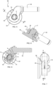
FIG. 3 is an exploded view of the turbocharger ofFIG. 2 , showing the poppet, rotary valve member, and retaining ring of the waste gate valve exploded away from the turbine housing; -
FIG. 4 is a cross-sectional view through the turbocharger ofFIG. 2 along a plane that is perpendicular to the pin of the valve poppet; -
FIG. 5 is a plan view of the rotary valve member; -
FIG. 6 is a cross-sectional view through the valve member along line 6-6 inFIG. 5 ; -
FIG. 7 is a side view of the rotary valve member; -
FIG. 8 is a cross-sectional view along line 8-8 inFIG. 7 ; -
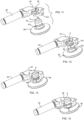
FIG. 9 is an exploded view of the rotary valve member and retaining ring, minus the poppet; -
FIG. 9A is a plan view of the retaining ring; -
FIG. 9B is a plan view of the rotary valve shaft and arm; -
FIG. 10 is an exploded view showing the rotary valve member with the retaining ring pre-installed therein, ready to be pushed onto the pin of the poppet; -
FIG. 11 is similar toFIG. 10 , but a portion of the arm has been removed to enable the retaining ring to be seen pre-installed in the arm groove; -
FIG. 12 illustrates initiation of a push-to-connect process to connect the arm to the poppet, wherein the tapered end of the pin begins to expand the retaining ring radially outwardly; -
FIG. 13 illustrates a later time in the push-to-connect process as the arm is pushed further onto the pin to further expand the retaining ring; -
FIG. 14 illustrates a still later time in the push-to-connect process when the arm groove has become aligned with the pin groove and the retaining ring has contracted radially inwardly so that portions of its sides are within the pin groove, thereby captively connecting the poppet to the arm; -
FIG. 15 is an exploded view showing an alternative embodiment of rotary valve member and retaining ring; -
FIG. 15A is a plan view of the retaining ring for the alternative embodiment; -
FIG. 16 is an exploded view of the rotary valve member with retaining ring pre-installed in its through bore, and the poppet ready for connection to the arm of the valve member; -
FIG. 17 is an exploded view showing the rotary valve member of the alternative embodiment with the retaining ring pre-installed therein, a portion of the arm having been removed to enable the retaining ring to be seen pre-installed in the arm groove, ready to be pushed onto the pin of the poppet; -
FIG. 18 illustrates initiation of a push-to-connect process to connect the arm to the poppet, wherein the tapered end of the pin begins to expand the retaining ring radially outwardly; -
FIG. 19 illustrates a later time in the push-to-connect process as the arm is pushed further onto the pin to further expand the retaining ring; -
FIG. 20 illustrates a still later time in the push-to-connect process when the arm groove has become aligned with the pin groove and the retaining ring has contracted radially inwardly so that portions of its sides are within the pin groove, thereby captively connecting the poppet to the arm; -
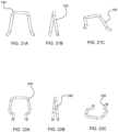
FIGS. 21A through 21C are top, side, and isometric views, respectively, of a retaining ring in accordance with one embodiment of the invention; and -
FIGS. 22A through 22C are top, side, and isometric views, respectively, of a retaining ring in accordance with a further embodiment of the invention. - The present disclosure will now be described in fuller detail with reference to the above-described drawings, which depict some but not all embodiments of the invention(s) to which the present disclosure pertains. These inventions may be embodied in various forms, including forms not expressly described herein, and should not be construed as limited to the particular exemplary embodiments described herein. In the following description, like numbers refer to like elements throughout.
-
FIG. 1 illustrates aturbocharger 10 in accordance with an embodiment of the invention. The turbocharger comprises acompressor 12 having a compressor wheel (not visible) mounted within acompressor housing 16 defining anair inlet 17 for the compressor, and aturbine 22 comprising a turbine wheel 25 (FIG. 3 ) mounted within aturbine housing 24 and connected to a shaft (not visible) that also connects with the compressor wheel. Acenter housing 20 is disposed between and secured to the compressor housing and turbine housing, and contains bearings for the shaft. - The
turbine housing 24 defines an annular chamber surrounding theturbine wheel 25 for receiving exhaust gas from an internal combustion engine (not shown). Exhaust gas is directed from the chamber via a turbine nozzle onto the turbine wheel. In some operating conditions, it is desirable to cause some of the exhaust gas to bypass the turbine wheel and proceed directly into the downstream exhaust conduit, and to this end, turbochargers typically include a waste gate valve 30 (FIGS. 2-4 ) arranged for opening and closing a bypass passage 29 (FIG. 3 ) defined by the turbine housing. The bypass passage connects between the exhaust gas chamber and the discharge bore of the turbine housing downstream of the turbine wheel. Thus, when the waste gate valve is opened, some of the exhaust gas passes through the valve and thereby bypasses the turbine wheel. - With reference to
FIG. 1 , regulation of the waste gate valve is accomplished by anactuator 40 connected to the valve via a kinematic linkage arrangement comprising a first crank C1, a linkage L, and a second crank C2. Thevalve 30 has arotary valve shaft 32, and one end of the first crank C1 is rigidly affixed to the valve shaft. Theactuator 40 has arotary output shaft 42, and one end of the second crank C2 is rigidly affixed to the output shaft. A first end of the linkage L is rotatably coupled to the first crank C1, and the opposite second end of the linkage is rotatably coupled to the second crank C2. Accordingly, rotation of theactuator shaft 42 causes two cranks and the linkage to impart rotation to thevalve shaft 32. - As best seen in
FIGS. 3 and4 , the turbine housing defines abearing hole 27 in which abushing 23 is installed, and thevalve shaft 32 of the waste gate valve extends through the bushing, which allows the shaft to rotate about its axis and thereby cause the valve to open or close thebypass passage 29. To this end, the turbine housing definesvalve seat 21 the surrounds the open end of the bypass passage. The waste gate valve includes apoppet 38 having a disc shape and being sized and configured to abut thevalve seat 21 so that the poppet closes the bypass passage. The poppet includes an integral pin P projecting from the center of the poppet normal to the plane of the disc. The pin is received into a throughbore 35 formed at a distal end of anarm 34 that is affixed to the end of thevalve shaft 32, the arm extending at an oblique angle to the valve shaft axis. The connection of the pin to the arm is accomplished by a retainingring 40 in a manner described below. - The retaining
ring 40 is formed from elastically deformable wire by any suitable process such as a rolling process as commonly used for rolling springs and the like, so that the retaining ring has a generally polygonal shape that is non-closed, i.e., a gap remains between the opposite ends of the wire. As shown inFIG. 9A , the ring is formed to have a plurality of vertices V and a plurality of sides S each of which extends between two of said vertices. In the embodiment ofFIG. 9A , the retaining ring is generally U-shaped, having two vertices V and three sides S. The terms "vertex" and "vertices" do not require or imply that they must be sharp corners, which in practice would be impossible, it always being necessary to have a non-zero radius of curvature of the wire at each vertex. Also, the term "side" does not require or imply that the sides must be linear, although linear sides can be used as shown in the drawings. - As noted, the
arm 34 defines a throughbore 35. The inner surface of the bore defines an arm groove AG at least partially encircling the central axis of the bore. The radial depth and the axial length of the arm groove are sized in relation to the diameter of the wire so that portions of the wire can be received into the arm groove. - Providing the retaining ring with vertices and sides enables the vertices V of the ring to be engaged in the arm groove AG while the sides S remain radially inward of the radially outer wall of the arm groove, as best seen in
FIG. 8 . Advantageously, the retainingring 40 is pre-installed in thearm 34 as shown inFIG. 10 , prior to connection to the pin of the poppet. To facilitate the installation of the retaining ring into the arm, the arm includes aslot 36 that extends from an outer face of the arm into the throughbore 35. The retaining ring is pushed through this slot until the vertices of the retaining ring are seated into the arm groove. The two ends of the retaining ring wire are flared away from each other with a spacing that exceeds the width of theslot 36. When the retaining ring is fully installed into the arm, the two ends of the wire project out from the slot and are compressed toward each other by the side walls of the slot (compareFIGS. 8 and9A ). - With respect to
FIG. 9B , the throughbore 35 in thearm 34 of the valve member is non-round. In the illustrated embodiment, the shape of the bore comprises a circle with a flat on one side. As shown inFIG. 10 , the pin P on thepoppet 38 correspondingly has a non-round cross-sectional shape consisting of a circle with a flat F on one side, complementing the non-round bore 35 in the arm. Accordingly, shape-locking occurs between these complementary shapes such that the poppet is prevented from rotating about the pin axis relative to the arm, thus comprising a non-rotation feature for the valve arrangement. - With respect to now to
FIGS. 11-14 , a push-to-connect process for connecting the poppet to the arm of the valve member is described. In these figures, a portion of thearm 34 has been removed so that the retainingring 40 can be seen.FIG. 11 shows the unconnected assembly prior to the push-to-connect process. The pin P of thepoppet 38 extends along a pin axis and terminates at a distal end. The generally cylindrical outer surface of the pin defines a pin groove PG therein. The radial depth and axial length of the pin groove are selected in relation to the diameter of the wire forming the retainingring 40. Distal of the pin groove, the pin defines a tapered end TE. Connection of thearm 34 having thepre-installed retaining ring 40 to the pin of the poppet is a simple push-to-connect process in which the tapered end of the pin contacts and urges the retaining ring to radially expand. More particularly, it is the sides S of the ring that are resiliently deformed radially outwardly (seeFIGS. 12 and 13 ). - Pushing the arm further onto the pin then will cause the arm groove AG to become aligned with the pin groove PG as best seen in
FIG. 14 . Once these grooves become aligned, the retainingring 40 resiliently returns toward its relaxed state, under the restoring force of the wire, and as a result, the sides S of the ring become engaged in the pin groove PG of the pin. At the same time, the vertices V of the retaining ring are engaged in the arm groove AG as depicted inFIG. 8 . The retaining ring thus captively retains the arm in connection with the pin to restrain axial movement of the arm along the pin axis. As previously noted, the arm is prevented from rotating relative to the pin by the shape-locking between the pin and the arm bore. The retaining ring allows a small amount of movement of thepoppet 38 relative to thearm 34 along the axial direction of the through-bore 35. Furthermore, when the retaining ring has a non-planar free shape (as in the embodiments ofFIGS. 21 and 22 , for example), it also exerts a biasing force on the poppet tending to urge the poppet against the valve seat when the valve is closed. -
FIGS. 15-20 illustrate a second embodiment of the invention in which the retainingring 40' has a different configuration and the anti-rotation feature also differs from that of the first embodiment. As seen inFIG. 15 , the modified arm 34' has a through bore 35' that is generally circular but connects with a further recess R in the arm to form a keyhole shape. Thepoppet 38' includes a key K comprising a short post or projection on one side of and extending parallel to the pin P'. When the poppet is connected to the arm 34', the key fits into the bottom side of the recess R and thereby prevents the poppet from rotating about the pin. The retainingring 40' (FIG. 15A ) is generally Omega-shaped, having four vertices V and three sides S.FIG. 16 shows the retaining ring pre-installed in the arm groove AG of the arm 34' (and in that state is relaxed or only slightly compressed radially inwardly by the outer wall of the groove). The two ends of the wire extend into the recess R. The retainingring 40' functions substantially like the retainingring 40 of the first embodiment. The tapered end TE of the pin expands the sides of the retaining ring radially outwardly as the arm is pushed onto the pin (FIGS. 18 and 19 ), and once the arm groove AG becomes aligned with the pin groove PG, the sides return toward their original configuration and the ring's vertices V are engaged in the arm groove while the sides S are engaged in the pin groove (FIG. 20 ). - The invention is not limited to any particular configuration of retaining ring. The embodiments described above include planar retaining rings, but the invention is not limited to planar rings.
FIGS. 21A through 21C depict an alternative embodiment of retainingring 140 that is generally U-shaped and non-planar.FIGS. 22A through 22C illustrate yet another embodiment of retainingring 240 that is generally Omega-shaped and non-planar. Other configurations (rectangular, triangular, pentagonal, etc.) may also be used. While the illustrated retaining rings have the two ends of the wire flared outwardly away from each other, it is also possible for the two ends to extend toward each other, or to be parallel to each other. - Persons skilled in the art, on the basis of the present disclosure, will recognize that modifications and other embodiments of the inventions described herein can be made without departing from the inventive concepts described herein. Specific terms used herein are employed for explanatory purposes rather than purposes of limitation. Accordingly, the inventions are not to be limited to the specific embodiments disclosed, and modifications and other embodiments are intended to be included within the scope of the appended claims.
Claims (10)
- A waste gate assembly for a turbocharger, comprising:a valve member comprising a poppet having a pin extending therefrom along a pin axis and terminating at a distal end of the pin, an outer surface of the pin defining a pin groove therein at least partially encircling the pin axis, the pin groove being spaced along the pin axis from the poppet;a valve shaft extending along a shaft axis;an arm affixed to one end of the valve shaft and extending therefrom at an oblique angle relative to the shaft axis and terminating at a distal end, the distal end defining a through bore adjacent the distal end, an inner surface of the through bore defining an arm groove therein, a lengthwise portion of the pin being disposed within the through bore of the arm such that the arm groove is aligned with the pin groove; anda retaining ring comprising an elastically deformable wire formed into a generally polygonal non-closed configuration such that the retaining ring defines a plurality of vertices and a plurality of sides and two ends, wherein each of said plurality of vertices is within the arm groove and at least two of the plurality of sides has a portion engaged in the pin groove, thereby restraining movement of the arm along the pin axis, and further comprising an anti-rotation feature preventing rotational movement of the poppet relative to the arm about the pin axis, whereby rotation of the valve shaft about the shaft axis causes the arm to move the poppet along an arc about the valve axis.
- The waste gate assembly of claim 1, wherein the anti-rotation feature is formed by shape locking between the pin having a non-round cross-sectional shape and the through bore in the arm having a corresponding non-round cross-sectional shape.
- The waste gate assembly of claim 1 or 2, wherein the anti-rotation feature comprises a recess defined in the arm and a projection formed on the poppet, the projection being received into the recess to prevent rotation of the poppet.
- The waste gate assembly of claim 3, wherein the two ends of the retaining ring extend into the recess defined in the arm.
- The waste gate assembly of any preceding claim, wherein the arm defines a slot extending from an outer surface of the arm to the through bore, and the two ends of the retaining ring extend through the slot.
- A turbocharger comprising a compressor and a turbine, the turbine comprising a turbine housing and a turbine wheel mounted therein, the turbine housing defining a bypass passage for exhaust gases to bypass the turbine wheel, and a valve seat surrounding an open end of the bypass passage, the turbocharger further comprising a waste gate assembly comprising:a valve member comprising a poppet having a pin extending therefrom along a pin axis and terminating at a distal end of the pin, an outer surface of the pin defining a pin groove therein at least partially encircling the pin axis, the pin groove being spaced along the pin axis from the poppet;a valve shaft extending along a shaft axis;an arm affixed to one end of the valve shaft and extending therefrom at an oblique angle relative to the shaft axis and terminating at a distal end, the distal end defining a through bore adjacent the distal end, an inner surface of the through bore defining an arm groove therein, a lengthwise portion of the pin being disposed within the through bore of the arm such that the arm groove is aligned with the pin groove; anda retaining ring comprising an elastically deformable wire formed into a generally polygonal non-closed configuration such that the retaining ring defines a plurality of vertices and a plurality of sides and two ends, wherein each of said plurality of vertices is within the arm groove and at least two of the plurality of sides has a portion engaged in the pin groove, thereby restraining movement of the arm along the pin axis, and further comprising an anti-rotation feature preventing rotational movement of the poppet relative to the arm about the pin axis, wherein the valve shaft extends through a bearing hole defined in the turbine housing, rotation of the valve shaft about the shaft axis causing the arm to move the poppet along an arc about the valve axis so as to either place the poppet in engagement with the valve seat to close the bypass passage or displace the poppet away from the valve seat to open the bypass passage.
- The turbocharger of claim 6, wherein the anti-rotation feature is formed by shape locking between the pin having a non-round cross-sectional shape and the through bore in the arm having a corresponding non-round cross-sectional shape.
- The turbocharger of claim 6 or 7, wherein the anti-rotation feature comprises a recess defined in the arm and a projection formed on the poppet, the projection being received into the recess to prevent rotation of the poppet.
- The turbocharger of claim 8, wherein the two ends of the retaining ring extend into the recess defined in the arm.
- The turbocharger of any of claims 6 to 9, wherein the arm defines a slot extending from an outer surface of the arm to the through bore, and the two ends of the retaining ring extend through the slot.
Applications Claiming Priority (1)
| Application Number | Priority Date | Filing Date | Title |
|---|---|---|---|
| US17/455,415 US11499562B1 (en) | 2021-11-18 | 2021-11-18 | Turbocharger waste gate poppet valve connected to rotary valve shaft by arm and retaining ring |
Publications (2)
| Publication Number | Publication Date |
|---|---|
| EP4183991A1 true EP4183991A1 (en) | 2023-05-24 |
| EP4183991B1 EP4183991B1 (en) | 2025-07-30 |
Family
ID=83692940
Family Applications (1)
| Application Number | Title | Priority Date | Filing Date |
|---|---|---|---|
| EP22194560.3A Active EP4183991B1 (en) | 2021-11-18 | 2022-09-08 | Turbocharger waste gate poppet valve connected to rotary valve shaft by arm and retaining ring |
Country Status (3)
| Country | Link |
|---|---|
| US (1) | US11499562B1 (en) |
| EP (1) | EP4183991B1 (en) |
| CN (1) | CN115853633B (en) |
Citations (6)
| Publication number | Priority date | Publication date | Assignee | Title |
|---|---|---|---|---|
| DE102009007574A1 (en) * | 2009-02-05 | 2010-08-19 | Continental Automotive Gmbh | Plate flap, for a turbocharger waste gate or bypass, has a holder for the operating component in a structured holding zone to prevent rotation |
| DE102010043147A1 (en) * | 2010-04-27 | 2011-10-27 | Bosch Mahle Turbo Systems Gmbh & Co. Kg | Charging device i.e. exhaust gas turbocharger, has control lever arranged on valve disk, and resilient clamping element provided such that valve disk is biased against control lever and fixed at predefined location on lever |
| DE102011076361A1 (en) * | 2011-05-24 | 2012-11-29 | Bosch Mahle Turbo Systems Gmbh & Co. Kg | Valve device for controlling bypass of turbine of exhaust-gas turbocharger of internal combustion engine in motor vehicle, has centering element for centering mandrel in hole in transverse direction oriented transverse to central axis |
| DE102012201011A1 (en) * | 2012-01-24 | 2013-07-25 | Bosch Mahle Turbo Systems Gmbh & Co. Kg | Flap mechanism i.e. waste gate-flap mechanism, for exhaust turbocharger system of vehicle, has waste gate plate including receiving groove for partially receiving securing ring, which fastens waste gate plate at spindle |
| DE102017202137A1 (en) * | 2017-02-10 | 2018-08-16 | Continental Automotive Gmbh | Damper device for opening and closing a wastegate channel in a turbine housing of a turbocharger and turbocharger |
| WO2020119860A1 (en) * | 2018-12-11 | 2020-06-18 | Ihi Charging Systems International Gmbh | Valve device for a turbocharger, and turbocharger |
Family Cites Families (7)
| Publication number | Priority date | Publication date | Assignee | Title |
|---|---|---|---|---|
| DE102015209823A1 (en) * | 2015-05-28 | 2016-12-01 | Bosch Mahle Turbo Systems Gmbh & Co. Kg | actuator |
| DE102016104840A1 (en) * | 2016-03-16 | 2017-09-21 | Elringklinger Ag | Valve device for a turbocharger |
| DE102017218297A1 (en) * | 2017-10-12 | 2019-04-18 | Continental Automotive Gmbh | Valve flap device for a bypass valve of an exhaust gas turbocharger and exhaust gas turbocharger |
| EP3477071B1 (en) * | 2017-10-26 | 2021-02-17 | Garrett Transportation I Inc. | Turbocharger turbine wastegate assembly |
| DE102018217240A1 (en) * | 2018-10-09 | 2020-04-09 | Continental Automotive Gmbh | Exhaust gas turbocharger with an actuator-operated actuator and a transmission element with a one-piece component body |
| CN112555194B (en) * | 2019-09-26 | 2022-11-01 | 纬湃科技投资(中国)有限公司 | Volute assembly and turbocharger |
| US11352945B1 (en) * | 2021-06-23 | 2022-06-07 | Garrett Transportation I Inc. | Push-to-connect crank and linkage assembly for a turbocharger, and associated assembly method |
-
2021
- 2021-11-18 US US17/455,415 patent/US11499562B1/en active Active
-
2022
- 2022-09-08 EP EP22194560.3A patent/EP4183991B1/en active Active
- 2022-11-18 CN CN202211444493.9A patent/CN115853633B/en active Active
Patent Citations (6)
| Publication number | Priority date | Publication date | Assignee | Title |
|---|---|---|---|---|
| DE102009007574A1 (en) * | 2009-02-05 | 2010-08-19 | Continental Automotive Gmbh | Plate flap, for a turbocharger waste gate or bypass, has a holder for the operating component in a structured holding zone to prevent rotation |
| DE102010043147A1 (en) * | 2010-04-27 | 2011-10-27 | Bosch Mahle Turbo Systems Gmbh & Co. Kg | Charging device i.e. exhaust gas turbocharger, has control lever arranged on valve disk, and resilient clamping element provided such that valve disk is biased against control lever and fixed at predefined location on lever |
| DE102011076361A1 (en) * | 2011-05-24 | 2012-11-29 | Bosch Mahle Turbo Systems Gmbh & Co. Kg | Valve device for controlling bypass of turbine of exhaust-gas turbocharger of internal combustion engine in motor vehicle, has centering element for centering mandrel in hole in transverse direction oriented transverse to central axis |
| DE102012201011A1 (en) * | 2012-01-24 | 2013-07-25 | Bosch Mahle Turbo Systems Gmbh & Co. Kg | Flap mechanism i.e. waste gate-flap mechanism, for exhaust turbocharger system of vehicle, has waste gate plate including receiving groove for partially receiving securing ring, which fastens waste gate plate at spindle |
| DE102017202137A1 (en) * | 2017-02-10 | 2018-08-16 | Continental Automotive Gmbh | Damper device for opening and closing a wastegate channel in a turbine housing of a turbocharger and turbocharger |
| WO2020119860A1 (en) * | 2018-12-11 | 2020-06-18 | Ihi Charging Systems International Gmbh | Valve device for a turbocharger, and turbocharger |
Also Published As
| Publication number | Publication date |
|---|---|
| CN115853633A (en) | 2023-03-28 |
| CN115853633B (en) | 2024-03-19 |
| US11499562B1 (en) | 2022-11-15 |
| EP4183991B1 (en) | 2025-07-30 |
Similar Documents
| Publication | Publication Date | Title |
|---|---|---|
| US6419464B1 (en) | Vane for variable nozzle turbocharger | |
| US6527508B2 (en) | Actuator crank arm design for variable nozzle turbocharger | |
| JP4118041B2 (en) | Contact structure between inlet guide vane and shroud support | |
| US7011494B2 (en) | Dual retention vane arm | |
| US8033109B2 (en) | Variable-nozzle assembly for a turbocharger | |
| US20030010029A1 (en) | Variable geometry turbine | |
| EP4141234B1 (en) | Turbocharger turbine rotary bypass valve providing waste gate regulation and full turbine bypass functions | |
| CN212583765U (en) | Coupling assembly and turbocharger comprising a coupling assembly | |
| US6928818B1 (en) | Actuation assembly for variable geometry turbochargers | |
| WO1989011583A1 (en) | Turbocharger apparatus | |
| EP4108893B1 (en) | Push-to-connect crank and linkage assembly for a turbocharger, and associated assembly method | |
| US11499562B1 (en) | Turbocharger waste gate poppet valve connected to rotary valve shaft by arm and retaining ring | |
| US20190136753A1 (en) | Turbocharger wastegate actuator assembly | |
| EP1481151A1 (en) | Improved vane design for use in variable geometry-turbocharger | |
| EP3219931B1 (en) | Vane assembly and corresponding gas turbine engine | |
| US20230304417A1 (en) | Vane arm torque transfer plate | |
| US12000330B1 (en) | Push-to-connect crank and linkage assembly for a turbocharger, and associated assembly method |
Legal Events
| Date | Code | Title | Description |
|---|---|---|---|
| PUAI | Public reference made under article 153(3) epc to a published international application that has entered the european phase |
Free format text: ORIGINAL CODE: 0009012 |
|
| STAA | Information on the status of an ep patent application or granted ep patent |
Free format text: STATUS: REQUEST FOR EXAMINATION WAS MADE |
|
| 17P | Request for examination filed |
Effective date: 20220908 |
|
| AK | Designated contracting states |
Kind code of ref document: A1 Designated state(s): AL AT BE BG CH CY CZ DE DK EE ES FI FR GB GR HR HU IE IS IT LI LT LU LV MC MK MT NL NO PL PT RO RS SE SI SK SM TR |
|
| STAA | Information on the status of an ep patent application or granted ep patent |
Free format text: STATUS: EXAMINATION IS IN PROGRESS |
|
| 17Q | First examination report despatched |
Effective date: 20241223 |
|
| RIC1 | Information provided on ipc code assigned before grant |
Ipc: F01D 17/10 20060101ALI20250320BHEP Ipc: F16K 1/20 20060101ALI20250320BHEP Ipc: F16K 1/48 20060101ALI20250320BHEP Ipc: F16K 31/52 20060101ALI20250320BHEP Ipc: F02B 37/18 20060101AFI20250320BHEP |
|
| GRAP | Despatch of communication of intention to grant a patent |
Free format text: ORIGINAL CODE: EPIDOSNIGR1 |
|
| STAA | Information on the status of an ep patent application or granted ep patent |
Free format text: STATUS: GRANT OF PATENT IS INTENDED |
|
| INTG | Intention to grant announced |
Effective date: 20250502 |
|
| GRAS | Grant fee paid |
Free format text: ORIGINAL CODE: EPIDOSNIGR3 |
|
| GRAA | (expected) grant |
Free format text: ORIGINAL CODE: 0009210 |
|
| STAA | Information on the status of an ep patent application or granted ep patent |
Free format text: STATUS: THE PATENT HAS BEEN GRANTED |
|
| AK | Designated contracting states |
Kind code of ref document: B1 Designated state(s): AL AT BE BG CH CY CZ DE DK EE ES FI FR GB GR HR HU IE IS IT LI LT LU LV MC MK MT NL NO PL PT RO RS SE SI SK SM TR |
|
| REG | Reference to a national code |
Ref country code: GB Ref legal event code: FG4D |
|
| REG | Reference to a national code |
Ref country code: CH Ref legal event code: EP |
|
| REG | Reference to a national code |
Ref country code: DE Ref legal event code: R096 Ref document number: 602022018356 Country of ref document: DE |
|
| REG | Reference to a national code |
Ref country code: IE Ref legal event code: FG4D |
|
| PGFP | Annual fee paid to national office [announced via postgrant information from national office to epo] |
Ref country code: DE Payment date: 20250926 Year of fee payment: 4 |
|
| PGFP | Annual fee paid to national office [announced via postgrant information from national office to epo] |
Ref country code: FR Payment date: 20250925 Year of fee payment: 4 Ref country code: AT Payment date: 20251020 Year of fee payment: 4 |
|
| REG | Reference to a national code |
Ref country code: NL Ref legal event code: MP Effective date: 20250730 |
|
| REG | Reference to a national code |
Ref country code: AT Ref legal event code: MK05 Ref document number: 1819139 Country of ref document: AT Kind code of ref document: T Effective date: 20250730 |
|
| PG25 | Lapsed in a contracting state [announced via postgrant information from national office to epo] |
Ref country code: PT Free format text: LAPSE BECAUSE OF FAILURE TO SUBMIT A TRANSLATION OF THE DESCRIPTION OR TO PAY THE FEE WITHIN THE PRESCRIBED TIME-LIMIT Effective date: 20251202 |
|
| PG25 | Lapsed in a contracting state [announced via postgrant information from national office to epo] |
Ref country code: IS Free format text: LAPSE BECAUSE OF FAILURE TO SUBMIT A TRANSLATION OF THE DESCRIPTION OR TO PAY THE FEE WITHIN THE PRESCRIBED TIME-LIMIT Effective date: 20251130 |
|
| PG25 | Lapsed in a contracting state [announced via postgrant information from national office to epo] |
Ref country code: NO Free format text: LAPSE BECAUSE OF FAILURE TO SUBMIT A TRANSLATION OF THE DESCRIPTION OR TO PAY THE FEE WITHIN THE PRESCRIBED TIME-LIMIT Effective date: 20251030 |
|
| REG | Reference to a national code |
Ref country code: LT Ref legal event code: MG9D |
|
| PG25 | Lapsed in a contracting state [announced via postgrant information from national office to epo] |
Ref country code: AT Free format text: LAPSE BECAUSE OF FAILURE TO SUBMIT A TRANSLATION OF THE DESCRIPTION OR TO PAY THE FEE WITHIN THE PRESCRIBED TIME-LIMIT Effective date: 20250730 |
|
| PG25 | Lapsed in a contracting state [announced via postgrant information from national office to epo] |
Ref country code: FI Free format text: LAPSE BECAUSE OF FAILURE TO SUBMIT A TRANSLATION OF THE DESCRIPTION OR TO PAY THE FEE WITHIN THE PRESCRIBED TIME-LIMIT Effective date: 20250730 |
|
| PG25 | Lapsed in a contracting state [announced via postgrant information from national office to epo] |
Ref country code: HR Free format text: LAPSE BECAUSE OF FAILURE TO SUBMIT A TRANSLATION OF THE DESCRIPTION OR TO PAY THE FEE WITHIN THE PRESCRIBED TIME-LIMIT Effective date: 20250730 Ref country code: NL Free format text: LAPSE BECAUSE OF FAILURE TO SUBMIT A TRANSLATION OF THE DESCRIPTION OR TO PAY THE FEE WITHIN THE PRESCRIBED TIME-LIMIT Effective date: 20250730 |
|
| PG25 | Lapsed in a contracting state [announced via postgrant information from national office to epo] |
Ref country code: GR Free format text: LAPSE BECAUSE OF FAILURE TO SUBMIT A TRANSLATION OF THE DESCRIPTION OR TO PAY THE FEE WITHIN THE PRESCRIBED TIME-LIMIT Effective date: 20251031 |
|
| PG25 | Lapsed in a contracting state [announced via postgrant information from national office to epo] |
Ref country code: SE Free format text: LAPSE BECAUSE OF FAILURE TO SUBMIT A TRANSLATION OF THE DESCRIPTION OR TO PAY THE FEE WITHIN THE PRESCRIBED TIME-LIMIT Effective date: 20250730 |
|
| PG25 | Lapsed in a contracting state [announced via postgrant information from national office to epo] |
Ref country code: LV Free format text: LAPSE BECAUSE OF FAILURE TO SUBMIT A TRANSLATION OF THE DESCRIPTION OR TO PAY THE FEE WITHIN THE PRESCRIBED TIME-LIMIT Effective date: 20250730 |
|
| PG25 | Lapsed in a contracting state [announced via postgrant information from national office to epo] |
Ref country code: BG Free format text: LAPSE BECAUSE OF FAILURE TO SUBMIT A TRANSLATION OF THE DESCRIPTION OR TO PAY THE FEE WITHIN THE PRESCRIBED TIME-LIMIT Effective date: 20250730 Ref country code: PL Free format text: LAPSE BECAUSE OF FAILURE TO SUBMIT A TRANSLATION OF THE DESCRIPTION OR TO PAY THE FEE WITHIN THE PRESCRIBED TIME-LIMIT Effective date: 20250730 |
|
| PG25 | Lapsed in a contracting state [announced via postgrant information from national office to epo] |
Ref country code: RS Free format text: LAPSE BECAUSE OF FAILURE TO SUBMIT A TRANSLATION OF THE DESCRIPTION OR TO PAY THE FEE WITHIN THE PRESCRIBED TIME-LIMIT Effective date: 20251030 |
|
| PG25 | Lapsed in a contracting state [announced via postgrant information from national office to epo] |
Ref country code: ES Free format text: LAPSE BECAUSE OF FAILURE TO SUBMIT A TRANSLATION OF THE DESCRIPTION OR TO PAY THE FEE WITHIN THE PRESCRIBED TIME-LIMIT Effective date: 20250730 |
|
| PG25 | Lapsed in a contracting state [announced via postgrant information from national office to epo] |
Ref country code: RO Free format text: LAPSE BECAUSE OF FAILURE TO SUBMIT A TRANSLATION OF THE DESCRIPTION OR TO PAY THE FEE WITHIN THE PRESCRIBED TIME-LIMIT Effective date: 20250730 |
|
| PG25 | Lapsed in a contracting state [announced via postgrant information from national office to epo] |
Ref country code: SM Free format text: LAPSE BECAUSE OF FAILURE TO SUBMIT A TRANSLATION OF THE DESCRIPTION OR TO PAY THE FEE WITHIN THE PRESCRIBED TIME-LIMIT Effective date: 20250730 |
|
| PG25 | Lapsed in a contracting state [announced via postgrant information from national office to epo] |
Ref country code: DK Free format text: LAPSE BECAUSE OF FAILURE TO SUBMIT A TRANSLATION OF THE DESCRIPTION OR TO PAY THE FEE WITHIN THE PRESCRIBED TIME-LIMIT Effective date: 20250730 |
|
| PG25 | Lapsed in a contracting state [announced via postgrant information from national office to epo] |
Ref country code: IT Free format text: LAPSE BECAUSE OF FAILURE TO SUBMIT A TRANSLATION OF THE DESCRIPTION OR TO PAY THE FEE WITHIN THE PRESCRIBED TIME-LIMIT Effective date: 20250730 |
|
| PG25 | Lapsed in a contracting state [announced via postgrant information from national office to epo] |
Ref country code: CZ Free format text: LAPSE BECAUSE OF FAILURE TO SUBMIT A TRANSLATION OF THE DESCRIPTION OR TO PAY THE FEE WITHIN THE PRESCRIBED TIME-LIMIT Effective date: 20250730 |
|
| PG25 | Lapsed in a contracting state [announced via postgrant information from national office to epo] |
Ref country code: EE Free format text: LAPSE BECAUSE OF FAILURE TO SUBMIT A TRANSLATION OF THE DESCRIPTION OR TO PAY THE FEE WITHIN THE PRESCRIBED TIME-LIMIT Effective date: 20250730 Ref country code: SK Free format text: LAPSE BECAUSE OF FAILURE TO SUBMIT A TRANSLATION OF THE DESCRIPTION OR TO PAY THE FEE WITHIN THE PRESCRIBED TIME-LIMIT Effective date: 20250730 |
|
| REG | Reference to a national code |
Ref country code: CH Ref legal event code: H13 Free format text: ST27 STATUS EVENT CODE: U-0-0-H10-H13 (AS PROVIDED BY THE NATIONAL OFFICE) Effective date: 20260504 |