EP4183732A1 - A safety system for releasing a rope - Google Patents
A safety system for releasing a rope Download PDFInfo
- Publication number
- EP4183732A1 EP4183732A1 EP21210422.8A EP21210422A EP4183732A1 EP 4183732 A1 EP4183732 A1 EP 4183732A1 EP 21210422 A EP21210422 A EP 21210422A EP 4183732 A1 EP4183732 A1 EP 4183732A1
- Authority
- EP
- European Patent Office
- Prior art keywords
- rope
- safety system
- swinging
- mentioned
- cable
- Prior art date
- Legal status (The legal status is an assumption and is not a legal conclusion. Google has not performed a legal analysis and makes no representation as to the accuracy of the status listed.)
- Pending
Links
Images



Classifications
-
- B—PERFORMING OPERATIONS; TRANSPORTING
- B66—HOISTING; LIFTING; HAULING
- B66C—CRANES; LOAD-ENGAGING ELEMENTS OR DEVICES FOR CRANES, CAPSTANS, WINCHES, OR TACKLES
- B66C13/00—Other constructional features or details
- B66C13/04—Auxiliary devices for controlling movements of suspended loads, or preventing cable slack
- B66C13/06—Auxiliary devices for controlling movements of suspended loads, or preventing cable slack for minimising or preventing longitudinal or transverse swinging of loads
- B66C13/063—Auxiliary devices for controlling movements of suspended loads, or preventing cable slack for minimising or preventing longitudinal or transverse swinging of loads electrical
Definitions
- the present invention relates to a rope swinging safety system, which aims to eliminate the safety risks caused by a rope swinging process in rope cranes and prevents a lifting process when a determined swinging limit is reached, and in which an amount of swinging can be adjusted automatically, manually or by means of a remote controller, thus easily adapting to different situations, wherein the safety system is capable of informing a user by a visual warning, as well as electronically transmitting whether the limit is exceeded or not.
- Some limiters are provided in crane systems to keep a rope angle at a certain value. It is often not possible to easily change their limit values. Therefore, the lifting speeds determined at the heaviest load in the initial design of the system generally have to be applied to lower loads, leading to significant efficiency losses.
- the rope swinging limits need to be adjusted, which requires changing the rope angle measuring devices in the prior art or re-adjusting such devices, if possible, by physically reaching them. In this case, it causes significant losses in terms of time, labour and productivity. In addition, it creates security risks due to the possibility of inputting incorrect swinging values by the user.
- the swinging process is usually limited to angle values only in the x and y axis, which causes computational difficulties.
- the measuring device in order to determine the rope angle correctly in the current technique, the measuring device must be mounted in a region close to the highest point of the fixed end of the rope. This complicates accessing the device when adjustments are required. For that reason, alternative wired and wireless access facilities providing access to the device are needed.
- Another technical disadvantage is having a lot of sensors that limit operation of the crane, in which case it is important for the user to know which or which of them has stopped working safely. For example, if an overload warning is given in case of an excessive weight, the user can understand that the load cannot be lifted safely, and reduce the load. Likewise, if the load is prevented from being lifted due to the rope swinging value, this also needs to be notified to the user by means of a visual warning.
- the rope swinging safety system which is the subject of the invention, provides successful solutions to the technical problems mentioned above.
- the rope swinging safety system which is the subject of the invention, is a product consisting of two basic parts, a device and a control. It enables that the rope swinging values of the crane are controlled, adjustment of the incorrect swinging values is not allowed, adjustment processes are uncomplicated, adjustments are made valid for all circular swinging directions, thus the swinging values are adjusted both automatically and manually depending on the load, the vertical and horizontal movement speeds are increased and decreased in a safe manner so that the efficiency is improved, the swinging value is calculated and limited automatically by using the angular or operation area radius and height distance when necessary, the user is notified by means of visual warnings whether the limit values have been reached or not, and the adjustments and notification of reaching the limit can be made with the remote controller.
- the rope drum of the crane (1) is fixed in the highest possible fixed end of the rope (2) between a sufficient number of rope supports for lower body (32), which are located on the rear part of the lower body (30) of the device (3), by means of a sufficient number of rope grabbers (7), bolts (8) and flanged nuts (9).
- the rope support for lower body (32) is in even numbers, each pair positioned perpendicular to each other.
- the system can easily adapt to ropes of different thicknesses. Thanks to the positioning in the highest possible fixed end of the rope (2), a vertical view for the designed lifting height is achieved and it is possible to detect the swinging of the rope (2) more accurately.
- a display (11), a decrement button (12) and an increment button (13), which all have a suitable size, are provided on the device (3).
- Rope swinging value can be decreased by the decrement button (12) and increased by the increment button (13), in terms of angle and/or distance, and the changed values can be displayed on the display (11). In this way, adjustment can be made manually.
- a safe operation light (14) and a safe stop light (15), which all have a suitable size, are provided on the device (3). If the system operates within the adjusted limits, the safe operation light (14) informs the user that the swinging limit is not exceeded and the system is operating correctly. If the limit is exceeded, the lifting operation is not allowed and the safety stop light (15) and the warning light (10) inform the user that the swinging limit has been exceeded, so the lifting cannot be performed.
- a cable communication connector (5) and a connecting cable entry (6) are also provided on the device (3).
- a connection to the system is provided by cables, and limit values can be adjusted and controlled. In this case, whether the limit value is exceeded or not is transmitted to the wired controller of the crane, and visual warnings are provided.
- a protective cover for connector (16) is provided on the device (3), wherein the connector is prevented from being damaged by external environmental conditions when communication with cable is not provided.
- the device (3) comprises a joint gasket for body (33) located between the upper body (25) and the lower body (30).
- the coupling gasket for body (33) is positioned in the gasket groove for lower body (31) which is located on the lower body (30), so that it protects the coupling of the upper body (25) and the lower body (30) from the negative effects of outdoor conditions.
- the lower body (30) and the upper body (25) are connected to each other by means of a sufficient number of connecting screws for body (34).
- the upper connection cover gasket for cable (23) located between the upper body (25) and the upper connection cover for cable (22) is positioned in the gasket groove for upper body (35) provided in the upper part of the upper body (25), the junction point can be protected from the negative effects of outdoor conditions.
- the upper connection cover for cable (22) is connected to the upper body (25) by means of a sufficient number of upper connection cover screws for cable (24).
- the upper connection cover for cable (22) is made of a transparent material which is completely light-transparent or only the front surface of which is light-transparent. In this way, it is possible to warn the user from a suitable distance via the warning light (10). While the device (3) is operating safely, the safe working light (14) and the warning light (10) are lighted in green. If the device (3) does not allow the lifting operation due to exceeding the limit values, the safety stop light (15) and the warning light (10) are lighted in red. Therefore, according to the colour of the warning light (10), the user can detect from a suitable distance whether the limit values are exceeded, so that he can take precautions.
- the rope swinging safety system has at least one power board(28) for supplying energy from different power sources; at least one communication board(29) for making adjustments by connecting to the system via both wired and wireless communication; at least one sensor board(27) for measuring the swinging of rope in type of angle; and at least one control board (26) which calculates the safe working area and angle values and comprises user buttons and indicators for parameter settings in order to record the limit values, to record the measured values, to compare the measured values with the limit values, and to prevent an incorrect input by the user.
- the remote controller (4) provides a wireless access to the device (3).
- Limit values and whether the limit values are exceeded or not are provided to the user over the display for controller (17).
- the angle or distance can be decreased with the control value decrease button (18) and increased with the control value increase button (20), and the appropriate value can be confirmed and recorded with the control confirmation button (19).
- the user is warned and measures are taken easily.
- the rope swinging safety system which brings successful solutions to the technical problems mentioned above, is a product that can be produced like other crane safety parts.
Landscapes
- Engineering & Computer Science (AREA)
- Mechanical Engineering (AREA)
- Control And Safety Of Cranes (AREA)
Abstract
Description
- The present invention relates to a rope swinging safety system, which aims to eliminate the safety risks caused by a rope swinging process in rope cranes and prevents a lifting process when a determined swinging limit is reached, and in which an amount of swinging can be adjusted automatically, manually or by means of a remote controller, thus easily adapting to different situations, wherein the safety system is capable of informing a user by a visual warning, as well as electronically transmitting whether the limit is exceeded or not.
- There are various safety systems for the safe operation of cranes available in the market. The most important of these are weight sensors. By means of these sensors, the load is tried to be prevented from being lifted beyond the crane capacity; however, these structures calculate the vertical effects of the load. Especially on rope cranes, however, the loads caused by the swinging of the rope affect the system in a different manner from the values predicted in the vertical weight sensor data. Despite working with loads below the lifting limit, these effects may cause the drum to break, the rope or hook to be damaged, and accidents that may put the safety of life and property at risk. Therefore, it is of great importance to keep the effect of dynamic loads arising from a swinging process under controller. In order to achieve this, solutions such as reducing the speed of lifting and horizontal transport movements, and balancing the dynamic loads by creating much heavier and costly structures are recommended in the current solution.
- Some limiters are provided in crane systems to keep a rope angle at a certain value. It is often not possible to easily change their limit values. Therefore, the lifting speeds determined at the heaviest load in the initial design of the system generally have to be applied to lower loads, leading to significant efficiency losses.
- In order for lower weight loads to be carried at higher speeds, the rope swinging limits need to be adjusted, which requires changing the rope angle measuring devices in the prior art or re-adjusting such devices, if possible, by physically reaching them. In this case, it causes significant losses in terms of time, labour and productivity. In addition, it creates security risks due to the possibility of inputting incorrect swinging values by the user. The swinging process is usually limited to angle values only in the x and y axis, which causes computational difficulties. In the current solutions, according to the devices for limiting back and forth and left and right movements, not only the adjustment difficulties are experienced, but also, for example, 3 cm of movement in the x-axis and 4 cm of movement in the y-axis can be allowed, which means 5 cm of swinging is allowed in the hypotenuse of the x and y axis. A standard user can often ignore this. Moreover, since ignoring these details makes it difficult to make both safe and precise adjustments, the capacity is generally cannot be fully used as the safety is put in the foreground. Also, insufficient use of capacity leads to ineffectiveness. Thus, there is a need for a user-friendly system not allowing a user to input an incorrect value so that the risks arising from incorrect adjustments are eliminated, which provides for an uncomplicated adjustment process such that only one increment and one decrement button are provided to make an adjustment, and adjustments are made valid for all circular swinging directions.
- In addition to all these technical disadvantages, in order to determine the rope angle correctly in the current technique, the measuring device must be mounted in a region close to the highest point of the fixed end of the rope. This complicates accessing the device when adjustments are required. For that reason, alternative wired and wireless access facilities providing access to the device are needed.
- Another technical disadvantage is having a lot of sensors that limit operation of the crane, in which case it is important for the user to know which or which of them has stopped working safely. For example, if an overload warning is given in case of an excessive weight, the user can understand that the load cannot be lifted safely, and reduce the load. Likewise, if the load is prevented from being lifted due to the rope swinging value, this also needs to be notified to the user by means of a visual warning.
- In order to eliminate these disadvantages, there is a need for a remote-controlled system in which the swinging value can be limited in terms of an angle or distance unit when necessary, and automatic swinging values are produced depending on the load such that the user is prevented from inputting an incorrect value.
- The rope swinging safety system, which is the subject of the invention, provides successful solutions to the technical problems mentioned above. The rope swinging safety system, which is the subject of the invention, is a product consisting of two basic parts, a device and a control. It enables that the rope swinging values of the crane are controlled, adjustment of the incorrect swinging values is not allowed, adjustment processes are uncomplicated, adjustments are made valid for all circular swinging directions, thus the swinging values are adjusted both automatically and manually depending on the load, the vertical and horizontal movement speeds are increased and decreased in a safe manner so that the efficiency is improved, the swinging value is calculated and limited automatically by using the angular or operation area radius and height distance when necessary, the user is notified by means of visual warnings whether the limit values have been reached or not, and the adjustments and notification of reaching the limit can be made with the remote controller.
-
-
Figure 1 is a perspective view of the elements constituting the rope swinging safety system. -
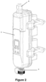
Figure 2 is a front perspective view of the device of the rope swinging safety system. -
Figure 3 is a rear perspective view of the device of the rope swinging safety systemFigure 4 is a perspective view of the rope swinging safety system device, applied on the rope of the crane. -
Figure 5 is a perspective view of the remote controller of the rope swinging safety system device -
Figure 6 is a detailed perspective view of the upper body of the rope swinging safety system device. -
Figure 7 is a detailed perspective view of the electronic circuit of the rope swinging safety system device. -
Figure 8 is a detailed perspective view of the lower body of the rope swinging safety system device. -
- 1:
- Rope drum of the crane
- 2:
- Rope
- 3:
- Device
- 4:
- Remote Controller
- 5:
- Cable communication connector
- 6:
- Connecting cable input
- 7:
- Rope gripper
- 8:
- Bolt
- 9:
- Flanged nut
- 10:
- Warning light
- 11:
- Display
- 12:
- Decrement button
- 13:
- Increment button
- 14:
- Safe operation light
- 15:
- Safe stop light
- 16:
- Protective cover for connector
- 17:
- Display for controller
- 18:
- Decrement button for controller
- 19:
- Confirmation button for controller
- 20:
- Increment button for controller
- 21:
- Decrement button for controller
- 22:
- Upper connection cover for cable
- 23:
- Upper connection cover gasket for cable
- 24:
- Upper connection cover screw for cable
- 25:
- Upper body
- 26:
- Control board
- 27:
- Sensor board
- 28:
- Power board
- 29:
- Communication circuit
- 30:
- Lower body
- 31:
- Gasket groove for lower body
- 32:
- Rope support for lower body
- 33:
- Joint gasket for body
- 34:
- Connecting screw for body
- 35:
- Gasket groove for upper body
- According to the rope swinging safety system, the rope drum of the crane (1) is fixed in the highest possible fixed end of the rope (2) between a sufficient number of rope supports for lower body (32), which are located on the rear part of the lower body (30) of the device (3), by means of a sufficient number of rope grabbers (7), bolts (8) and flanged nuts (9). The rope support for lower body (32) is in even numbers, each pair positioned perpendicular to each other. Thus, the system can easily adapt to ropes of different thicknesses. Thanks to the positioning in the highest possible fixed end of the rope (2), a vertical view for the designed lifting height is achieved and it is possible to detect the swinging of the rope (2) more accurately.
- According to the rope swinging safety system, a display (11), a decrement button (12) and an increment button (13), which all have a suitable size, are provided on the device (3). Rope swinging value can be decreased by the decrement button (12) and increased by the increment button (13), in terms of angle and/or distance, and the changed values can be displayed on the display (11). In this way, adjustment can be made manually.
- According to the rope swinging safety system, a safe operation light (14) and a safe stop light (15), which all have a suitable size, are provided on the device (3). If the system operates within the adjusted limits, the safe operation light (14) informs the user that the swinging limit is not exceeded and the system is operating correctly. If the limit is exceeded, the lifting operation is not allowed and the safety stop light (15) and the warning light (10) inform the user that the swinging limit has been exceeded, so the lifting cannot be performed.
- According to the rope swinging safety system, a cable communication connector (5) and a connecting cable entry (6) are also provided on the device (3). In this way, a connection to the system is provided by cables, and limit values can be adjusted and controlled. In this case, whether the limit value is exceeded or not is transmitted to the wired controller of the crane, and visual warnings are provided.
- According to the rope swinging safety system, a protective cover for connector (16) is provided on the device (3), wherein the connector is prevented from being damaged by external environmental conditions when communication with cable is not provided.
- According to the rope swinging safety system, the device (3) comprises a joint gasket for body (33) located between the upper body (25) and the lower body (30). The coupling gasket for body (33) is positioned in the gasket groove for lower body (31) which is located on the lower body (30), so that it protects the coupling of the upper body (25) and the lower body (30) from the negative effects of outdoor conditions. The lower body (30) and the upper body (25) are connected to each other by means of a sufficient number of connecting screws for body (34).
- Since the upper connection cover gasket for cable (23) located between the upper body (25) and the upper connection cover for cable (22) is positioned in the gasket groove for upper body (35) provided in the upper part of the upper body (25), the junction point can be protected from the negative effects of outdoor conditions. The upper connection cover for cable (22) is connected to the upper body (25) by means of a sufficient number of upper connection cover screws for cable (24).
- The upper connection cover for cable (22) is made of a transparent material which is completely light-transparent or only the front surface of which is light-transparent. In this way, it is possible to warn the user from a suitable distance via the warning light (10). While the device (3) is operating safely, the safe working light (14) and the warning light (10) are lighted in green. If the device (3) does not allow the lifting operation due to exceeding the limit values, the safety stop light (15) and the warning light (10) are lighted in red. Therefore, according to the colour of the warning light (10), the user can detect from a suitable distance whether the limit values are exceeded, so that he can take precautions.
- The rope swinging safety system, the device (3) has at least one power board(28) for supplying energy from different power sources; at least one communication board(29) for making adjustments by connecting to the system via both wired and wireless communication; at least one sensor board(27) for measuring the swinging of rope in type of angle; and at least one control board (26) which calculates the safe working area and angle values and comprises user buttons and indicators for parameter settings in order to record the limit values, to record the measured values, to compare the measured values with the limit values, and to prevent an incorrect input by the user.
- In the rope swinging safety system, the remote controller (4) provides a wireless access to the device (3). A display for controller (17), a decrement button for controller (18), a confirmation button for controller (19) and an increment button for controller (20), which all have a suitable size, are provided on the controller (4). Limit values and whether the limit values are exceeded or not are provided to the user over the display for controller (17).
- When the setting of the limit values is desired, the angle or distance can be decreased with the control value decrease button (18) and increased with the control value increase button (20), and the appropriate value can be confirmed and recorded with the control confirmation button (19). In case of exceeding the limit values, the user is warned and measures are taken easily.
- The rope swinging safety system, which brings successful solutions to the technical problems mentioned above, is a product that can be produced like other crane safety parts.
Claims (17)
- The subject of the invention is a rope swinging safety system, which is characterized in that device (3), whose feature allows the safety risks arising from the rope (2) oscillation to be kept under control, the oscillation values to be determined as the angle or the diameter of the safe working area and the rope length distance, and to be changed automatically and manually when necessary, and at least a remote control (4) providing wireless access to this device.
- A rope swinging safety system, characterized in that the device (3) mentioned in claim 1 has a display (11) of suitable size for displaying operational state and parameter settings; and a decrement button (12) and an increment button (13) for changing the parameters manually.
- A rope swinging safety system, characterized in that the device (3) mentioned in claim 1 has at least one safe working light (14) of suitable size, which informs the user visually that a safe operation is provided without exceeding the rope swinging limit; at least one safe stop light (15) of suitable size, which informs the user visually that lifting is not allowed because the rope swinging limit has been exceeded; and a warning light (10) of suitable size, which operates in synchronization with these lights.
- A rope swinging safety system, characterized in that the device (3) mentioned in claim 1 comprises a sufficient number of rope grabbers (7), bolts (8) and flanged nuts (9) for connection with the rope (2).
- A rope swinging safety system, characterized in that the device (3) mentioned in claim 1 comprises, at an inner part thereof, at least one power board (28) for supplying energy from different power sources; at least one communication circuit (29) for making adjustments by connecting to the system via both wired and wireless communication; at least one sensor board (27) in which a sufficient number of sensors are provided for measuring an angle of rope swing in all directions circularly; and at least one control board (26) which calculates the safe working area and angle values and comprises user buttons and indicators for parameter settings in order to record the limit values, to record the measured values, to compare the measured values with the limit values, and to prevent an incorrect input by the user.
- A rope swinging safety system, characterized in that the device (3) mentioned in claim 1 has a cable communication connector (5) which provides communication by connecting with a cable.
- A rope swinging safety system, characterized in that the cable communication connector (5) mentioned in claim 6 has a protective cover for connector (16) for preventing the connector from being damaged by the outer environment conditions.
- A rope swinging safety system, characterized in that the device (3) The device (3), whose feature is specified in claim 1, has upper body (25), lower body (30), cable upper connection cover (22), connection cables entry (6) and a sufficient number of lower body rope supports (32) on its outer part.
- The subject of the invention is a rope swinging safety system, which is characterized in that the lower body rope support (32) specified in claim 8 is in pairs so that it can easily adapt to the ropes (2) of different thicknesses and each pair is in a perpendicular position to each other.
- A rope swinging safety system, characterized in that the lower body (8) mentioned in claim 8 has a gasket groove for lower body (31).
- A rope swinging safety system, characterized in that a joint gasket for body (33) is provided in the gasket groove for lower body (31) between the upper body (25) and the lower body (30) mentioned in claim 8, which provides protection for junction point against negative effects of outdoor conditions.
- A rope swinging safety system, characterized in that the upper body (25) mentioned in claim 8 has a gasket groove for upper body (35).
- A rope swinging safety system, characterized in that an upper connection cover gasket for (23) cable is provided in the gasket groove for upper body (35) between the upper body (25) and the upper connection cover for cable (22) mentioned in claim 8, and which provides protection for junction point against negative effects of outdoor conditions.
- A rope swinging safety system, characterized by comprising a sufficient number of connecting screws for body (33) allowing the lower body (30) and the upper body (25) mentioned in claim 8 to be connected to each other.
- A rope swinging safety system, characterized by comprising a sufficient number of upper connection cover screw for cable (24) allowing the upper body (25) and the upper connection cover for cable (22) mentioned in claim 8 to be connected to each other.
- A rope swinging safety system, characterized in that the upper connection cover for cable (22) mentioned in claim 8 is made of a transparent material which is light-transparent.
- A rope swinging safety system, characterized in that the remote controller (4) mentioned in claim 1 has a display for remote controller (17) of a suitable size, which displays the limit values and whether the limit values have been exceeded or not; a decrement button for remote controller (18) which allows the swinging limit values to be decreased remotely, when desired, in terms of distance or angle; a confirmation button for remote controller (19) for remotely recording the adjusted value; and an increment button for remote controller (20) which allows the swinging limit values to be increased remotely, when desired, in terms of distance or angle.
Applications Claiming Priority (1)
| Application Number | Priority Date | Filing Date | Title |
|---|---|---|---|
| TR202117876 | 2021-11-17 |
Publications (1)
| Publication Number | Publication Date |
|---|---|
| EP4183732A1 true EP4183732A1 (en) | 2023-05-24 |
Family
ID=78916694
Family Applications (1)
| Application Number | Title | Priority Date | Filing Date |
|---|---|---|---|
| EP21210422.8A Pending EP4183732A1 (en) | 2021-11-17 | 2021-11-25 | A safety system for releasing a rope |
Country Status (1)
| Country | Link |
|---|---|
| EP (1) | EP4183732A1 (en) |
Citations (2)
| Publication number | Priority date | Publication date | Assignee | Title |
|---|---|---|---|---|
| WO2009138329A1 (en) * | 2008-05-16 | 2009-11-19 | Felice Vinati | A safety device for cable or chain lifting apparatus |
| TR201803852A2 (en) * | 2018-03-19 | 2018-06-21 | Elfatek Elektronik Makina Ve Otomasyonu Sanayi Ticaret Ltd Sirketi | Apparatus for Electronically Measuring / Adjusting Crane Rope Angle |
-
2021
- 2021-11-25 EP EP21210422.8A patent/EP4183732A1/en active Pending
Patent Citations (2)
| Publication number | Priority date | Publication date | Assignee | Title |
|---|---|---|---|---|
| WO2009138329A1 (en) * | 2008-05-16 | 2009-11-19 | Felice Vinati | A safety device for cable or chain lifting apparatus |
| TR201803852A2 (en) * | 2018-03-19 | 2018-06-21 | Elfatek Elektronik Makina Ve Otomasyonu Sanayi Ticaret Ltd Sirketi | Apparatus for Electronically Measuring / Adjusting Crane Rope Angle |
Similar Documents
| Publication | Publication Date | Title |
|---|---|---|
| US9944498B2 (en) | Crane and related method of operation | |
| TWI700235B (en) | Smart tower crane | |
| EP2858939B1 (en) | Crane and related method of operation | |
| EP2753568B1 (en) | Crane control | |
| US10850953B2 (en) | Lifting device, in particular a mobile crane or a cable-operated excavator, having an apparatus for monitoring the raising and lowering procedures of a boom system and corresponding method | |
| CN201473235U (en) | Stereo vision safety alarm system for tower crane | |
| CN105347211A (en) | Panorama-visible and controllable intelligent monitoring and protecting integrated system for tower crane | |
| US10961087B2 (en) | Arrangement of a controller and a mobile control module | |
| US20150142174A1 (en) | Crane and related method of operation | |
| AU2015342539A1 (en) | Operational fault detection system and method for winch of suspended platform in construction vertical shaft | |
| US20230150801A1 (en) | Rope swinging safety system | |
| CN101628692A (en) | Moment limiter for mini engineering crane | |
| KR101049192B1 (en) | Crane direction control system with built-in overload protection device using frequency of 2.4 ㎓ band | |
| US4273243A (en) | Lift centering device | |
| CN201458610U (en) | Moment limiter for small-sized engineering crane | |
| CN219929448U (en) | Device for preventing swing, rotation and tipping of tower crane suspended object | |
| US11891278B1 (en) | Lifting capacity systems and methods for lifting machines | |
| EP1490288B1 (en) | Load control system, preferably for boom cranes | |
| CN203112362U (en) | Horizontal monitoring device for fixed crane hang row | |
| CN203754274U (en) | System for monitoring fixed crane boom | |
| CN210438292U (en) | Tower Crane Wireless Lifting Weight Monitoring System | |
| CN203820339U (en) | Position monitoring system based on optical-electricity encoder and electronic compass of gantry crane | |
| CN103818831A (en) | Fixed crane boom monitoring system | |
| GB2504818A (en) | Personnel sensing to inhibit crane operation | |
| CN212953963U (en) | Crane lifting alarm device |
Legal Events
| Date | Code | Title | Description |
|---|---|---|---|
| PUAI | Public reference made under article 153(3) epc to a published international application that has entered the european phase |
Free format text: ORIGINAL CODE: 0009012 |
|
| STAA | Information on the status of an ep patent application or granted ep patent |
Free format text: STATUS: THE APPLICATION HAS BEEN PUBLISHED |
|
| AK | Designated contracting states |
Kind code of ref document: A1 Designated state(s): AL AT BE BG CH CY CZ DE DK EE ES FI FR GB GR HR HU IE IS IT LI LT LU LV MC MK MT NL NO PL PT RO RS SE SI SK SM TR |
|
| STAA | Information on the status of an ep patent application or granted ep patent |
Free format text: STATUS: REQUEST FOR EXAMINATION WAS MADE |
|
| 17P | Request for examination filed |
Effective date: 20231124 |
|
| RBV | Designated contracting states (corrected) |
Designated state(s): AL AT BE BG CH CY CZ DE DK EE ES FI FR GB GR HR HU IE IS IT LI LT LU LV MC MK MT NL NO PL PT RO RS SE SI SK SM TR |
|
| STAA | Information on the status of an ep patent application or granted ep patent |
Free format text: STATUS: EXAMINATION IS IN PROGRESS |
|
| 17Q | First examination report despatched |
Effective date: 20240626 |