EP4183628A1 - Adaptive headlamp control method, and terminal device and storage medium - Google Patents
Adaptive headlamp control method, and terminal device and storage medium Download PDFInfo
- Publication number
- EP4183628A1 EP4183628A1 EP20944869.5A EP20944869A EP4183628A1 EP 4183628 A1 EP4183628 A1 EP 4183628A1 EP 20944869 A EP20944869 A EP 20944869A EP 4183628 A1 EP4183628 A1 EP 4183628A1
- Authority
- EP
- European Patent Office
- Prior art keywords
- gradient
- gradient point
- point
- vehicle
- current position
- Prior art date
- Legal status (The legal status is an assumption and is not a legal conclusion. Google has not performed a legal analysis and makes no representation as to the accuracy of the status listed.)
- Pending
Links
- 230000003044 adaptive effect Effects 0.000 title claims abstract description 40
- 238000000034 method Methods 0.000 title claims abstract description 36
- 238000005286 illumination Methods 0.000 claims abstract description 17
- 238000012216 screening Methods 0.000 claims abstract description 5
- 238000004590 computer program Methods 0.000 claims description 20
- 230000006870 function Effects 0.000 claims description 5
- 230000035484 reaction time Effects 0.000 claims description 5
- 238000004364 calculation method Methods 0.000 claims description 4
- 238000005516 engineering process Methods 0.000 abstract description 3
- 238000010586 diagram Methods 0.000 description 3
- 230000000694 effects Effects 0.000 description 3
- 230000007613 environmental effect Effects 0.000 description 3
- 238000013500 data storage Methods 0.000 description 2
- 238000005457 optimization Methods 0.000 description 2
- 238000004458 analytical method Methods 0.000 description 1
- 230000007547 defect Effects 0.000 description 1
- 230000003287 optical effect Effects 0.000 description 1
Images
Classifications
-
- B—PERFORMING OPERATIONS; TRANSPORTING
- B60—VEHICLES IN GENERAL
- B60Q—ARRANGEMENT OF SIGNALLING OR LIGHTING DEVICES, THE MOUNTING OR SUPPORTING THEREOF OR CIRCUITS THEREFOR, FOR VEHICLES IN GENERAL
- B60Q1/00—Arrangement of optical signalling or lighting devices, the mounting or supporting thereof or circuits therefor
- B60Q1/02—Arrangement of optical signalling or lighting devices, the mounting or supporting thereof or circuits therefor the devices being primarily intended to illuminate the way ahead or to illuminate other areas of way or environments
- B60Q1/04—Arrangement of optical signalling or lighting devices, the mounting or supporting thereof or circuits therefor the devices being primarily intended to illuminate the way ahead or to illuminate other areas of way or environments the devices being headlights
- B60Q1/06—Arrangement of optical signalling or lighting devices, the mounting or supporting thereof or circuits therefor the devices being primarily intended to illuminate the way ahead or to illuminate other areas of way or environments the devices being headlights adjustable, e.g. remotely-controlled from inside vehicle
- B60Q1/08—Arrangement of optical signalling or lighting devices, the mounting or supporting thereof or circuits therefor the devices being primarily intended to illuminate the way ahead or to illuminate other areas of way or environments the devices being headlights adjustable, e.g. remotely-controlled from inside vehicle automatically
- B60Q1/085—Arrangement of optical signalling or lighting devices, the mounting or supporting thereof or circuits therefor the devices being primarily intended to illuminate the way ahead or to illuminate other areas of way or environments the devices being headlights adjustable, e.g. remotely-controlled from inside vehicle automatically due to special conditions, e.g. adverse weather, type of road, badly illuminated road signs or potential dangers
-
- B—PERFORMING OPERATIONS; TRANSPORTING
- B60—VEHICLES IN GENERAL
- B60Q—ARRANGEMENT OF SIGNALLING OR LIGHTING DEVICES, THE MOUNTING OR SUPPORTING THEREOF OR CIRCUITS THEREFOR, FOR VEHICLES IN GENERAL
- B60Q1/00—Arrangement of optical signalling or lighting devices, the mounting or supporting thereof or circuits therefor
- B60Q1/02—Arrangement of optical signalling or lighting devices, the mounting or supporting thereof or circuits therefor the devices being primarily intended to illuminate the way ahead or to illuminate other areas of way or environments
- B60Q1/04—Arrangement of optical signalling or lighting devices, the mounting or supporting thereof or circuits therefor the devices being primarily intended to illuminate the way ahead or to illuminate other areas of way or environments the devices being headlights
- B60Q1/06—Arrangement of optical signalling or lighting devices, the mounting or supporting thereof or circuits therefor the devices being primarily intended to illuminate the way ahead or to illuminate other areas of way or environments the devices being headlights adjustable, e.g. remotely-controlled from inside vehicle
- B60Q1/08—Arrangement of optical signalling or lighting devices, the mounting or supporting thereof or circuits therefor the devices being primarily intended to illuminate the way ahead or to illuminate other areas of way or environments the devices being headlights adjustable, e.g. remotely-controlled from inside vehicle automatically
- B60Q1/10—Arrangement of optical signalling or lighting devices, the mounting or supporting thereof or circuits therefor the devices being primarily intended to illuminate the way ahead or to illuminate other areas of way or environments the devices being headlights adjustable, e.g. remotely-controlled from inside vehicle automatically due to vehicle inclination, e.g. due to load distribution
- B60Q1/115—Arrangement of optical signalling or lighting devices, the mounting or supporting thereof or circuits therefor the devices being primarily intended to illuminate the way ahead or to illuminate other areas of way or environments the devices being headlights adjustable, e.g. remotely-controlled from inside vehicle automatically due to vehicle inclination, e.g. due to load distribution by electric means
-
- B—PERFORMING OPERATIONS; TRANSPORTING
- B60—VEHICLES IN GENERAL
- B60Q—ARRANGEMENT OF SIGNALLING OR LIGHTING DEVICES, THE MOUNTING OR SUPPORTING THEREOF OR CIRCUITS THEREFOR, FOR VEHICLES IN GENERAL
- B60Q2300/00—Indexing codes for automatically adjustable headlamps or automatically dimmable headlamps
- B60Q2300/10—Indexing codes relating to particular vehicle conditions
- B60Q2300/11—Linear movements of the vehicle
- B60Q2300/112—Vehicle speed
-
- B—PERFORMING OPERATIONS; TRANSPORTING
- B60—VEHICLES IN GENERAL
- B60Q—ARRANGEMENT OF SIGNALLING OR LIGHTING DEVICES, THE MOUNTING OR SUPPORTING THEREOF OR CIRCUITS THEREFOR, FOR VEHICLES IN GENERAL
- B60Q2300/00—Indexing codes for automatically adjustable headlamps or automatically dimmable headlamps
- B60Q2300/20—Indexing codes relating to the driver or the passengers
-
- B—PERFORMING OPERATIONS; TRANSPORTING
- B60—VEHICLES IN GENERAL
- B60Q—ARRANGEMENT OF SIGNALLING OR LIGHTING DEVICES, THE MOUNTING OR SUPPORTING THEREOF OR CIRCUITS THEREFOR, FOR VEHICLES IN GENERAL
- B60Q2300/00—Indexing codes for automatically adjustable headlamps or automatically dimmable headlamps
- B60Q2300/30—Indexing codes relating to the vehicle environment
- B60Q2300/32—Road surface or travel path
- B60Q2300/324—Road inclination, e.g. uphill or downhill
Definitions
- the present invention relates to the field of intelligent control of vehicles, and in particular to an adaptive front-lighting system control method and terminal device, and a storage medium.
- An adaptive front-lighting system is a technique that changes the horizontal angle and vertical angle of lighting according to the environment of the vehicle.
- a typical method is to adjust the horizontal front-lighting angle based on data collected by a steering wheel steering sensor or to adjust the vertical front-lighting angle through a body inclination sensor.
- the sensors can only obtain the current state of the vehicle environment, but cannot obtain the environment data of the road ahead of the vehicle, failing in predicting the conditions of the road ahead. For a lighting system, it is of the greatest significance to ensure the brightness of the road ahead. Therefore, the traditional method cannot achieve the best effect.
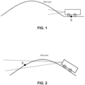
- this simple angle control may lead to a blind spot of illumination because of the change in the gradient.
- the illumination angle is selected according to the gradient S of the current position of the vehicle, and the blind spot of illumination is produced because of the change in the gradient ahead.
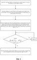
- the illumination angle is selected according to the gradient S of the expected farthest position of illumination. The lights cannot actually illuminate the expected position because of the difference between the gradient S of the expected farthest position of illumination and the gradient of the current position of the vehicle, causing the blind spot.
- the present invention provides an adaptive front-lighting system control method and terminal device, and a storage medium.
- an adaptive front-lighting system control method including: calculating, based on gradient values of different gradient points in electronic horizon data ahead, a to-be-adjusted vertical adjustment angle of the adaptive front-lighting system, and adjusting an illumination angle of the adaptive front-lighting system with the vertical adjustment angle.
- a method of calculating the to-be-adjusted vertical adjustment angle of the adaptive front-lighting system includes:
- the safe sight distance is calculated based on the current speed of vehicle and a driver reaction time.
- a method of calculating the view inclination of each gradient point relative to the current position of the vehicle includes:
- h i sign S i S i T i 1 + S i 2
- h i the vertical distance between the i -th gradient point and the ( i +1)-th gradient point
- S i represents the gradient value of the i-th gradient point
- T i represents the road length between the i -th gradient point and the ( i +1)-th gradient point.
- a method of screening the gradient points sequentially from the farthest gradient point within the safe sight distance includes:
- a method of setting the lighting angle range includes: setting the difference of view inclination corresponding to the gradient point as ⁇ ' t , and a maximum upward lighting angle and a maximum downward lighting angle of the adaptive front-lighting system as T 1 and T 2 respectively, and then obtaining the lighting angle range corresponding to the gradient point [ ⁇ ' t -T 2 , ⁇ ' t +T 1 ].
- an adaptive front-lighting system control terminal device including a processor, a memory, and a computer program stored in the memory and running in the processor.
- the processor when executing the computer program, implements the steps in the method in the embodiments of the present invention.
- a computer-readable storage medium having a computer program stored thereon.
- the computer program when executed by a processor, implements the steps in the method in the embodiments of the present invention.
- the present invention provides gradient information of the road out of view for control of the adaptive front-lighting system based on electronic horizon technology, optimizes the control of vertical angle, and can avoid the blind spot of illumination caused by the change in the gradient in simple angle control, thus being more suitable for the control of the adaptive front-lighting system in a gradient terrain.
- the present invention provides an adaptive front-lighting system control method, including the following steps: S1: Determine a safe sight distance D corresponding to a current position of a vehicle according to a current speed of vehicle.
- the driver reaction time can be set by those skilled in the art according to experience, and is not limited here.
- Get: Get: h i sign S i S i T i 1 + S i 2
- w i represents the horizontal distance between the i -th gradient point and the ( i +1)-th gradient point
- h i represents the vertical distance between the i -th gradient point and the ( i +1)-th gradient point
- T i represents the road length between the i -th gradient point and the ( i +1)-th gradient point.
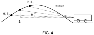
- S4 Determine whether there exists a gradient point S j , j ⁇ t, that satisfies ⁇ ' j ⁇ [ ⁇ ' t -T 2 , ⁇ ' t +T 1 ]; if so, it indicates that there exists a blind spot of illumination, as shown in FIG. 4 , and proceed to S5; otherwise, proceed to S6.
- Embodiment I of the present invention can predict the conditions of the road ahead according to the electronic horizon data so as to adjust the illumination angle of the adaptive front-lighting system.
- This technical solution not only overcomes the defect that the traditional camera or sensor has no foresight when acquiring the information of the road ahead, but also can adapt to the road conditions with complicated gradients.
- the adjustment angle is more appropriate, and this dynamic adjustment can affect other vehicles as little as possible (a too large adjustment angle may create a high beam effect on the oncoming vehicle and affect the safety of the driver in the oncoming vehicle).
- this embodiment also solves the problem of the blind spot of view that has not been solved in the prior art. By adjusting the selected angle, the lighting can be as long as possible, and there is no blind spot, which optimizes the control and ensures the vehicle safety.
- the technical effects above cannot be achieved only by simply adjusting a fixed angle according to the gradient value.
- the present invention further provides an adaptive front-lighting system control terminal device, including a memory, a processor, and a computer program stored in the memory and capable of running in the processor.
- the processor when executing the computer program, implements the steps in the method embodiment in Embodiment I of the present invention.
- the adaptive front-lighting system control terminal device may be an on-board computer, a cloud server or other computing devices.
- the adaptive front-lighting system control terminal device may include, but not limited to, a processor and a memory. It can be understood by those skilled in the art that the composition of the adaptive front-lighting system control terminal device is merely an example of the adaptive front-lighting system control terminal device, and does not constitute a limitation to the adaptive front-lighting system control terminal device.
- the adaptive front-lighting system control terminal device may include more or less components than the above, or a combination of some components, or different components.
- the adaptive front-lighting system control terminal device may further include input-output devices, network access devices, buses, etc., which is not limited by the embodiment of the present invention.
- the processor may be a central processing unit (CPU), other general-purpose processors, a digital signal processor (DSP), an application specific integrated circuit (ASIC), a field-programmable gate array (FPGA) or other programmable logic devices, a discrete gate or transistor logic device, a discrete hardware component, etc.
- the general-purpose processor may be a microprocessor, or the processor may also be any conventional processor, etc.
- the processor is the control center of the adaptive front-lighting system control terminal device, and connects all parts of the entire adaptive front-lighting system control terminal device using various interfaces and lines.
- the memory can be used for storing the computer program and/or module.
- the processor implements various functions of the adaptive front-lighting system control terminal device by running or executing the computer program and/or module stored in the memory and calling the data stored in the memory.
- the memory may mainly include a program storage area and a data storage area.
- the program storage area may store an operating system and application programs required by at least one function.
- the data storage area may store data created during running of the program, etc.
- the memory may include a high-speed random access memory, and may further include a non-volatile memory, such as a hard disk, an internal memory, a plug-in hard disk, a smart media card (SMC), a secure digital (SD) card, a flash card, at least one disk memory device, a flash memory device, or other volatile solid-state memory devices.
- a non-volatile memory such as a hard disk, an internal memory, a plug-in hard disk, a smart media card (SMC), a secure digital (SD) card, a flash card, at least one disk memory device, a flash memory device, or other volatile solid-state memory devices.
- the present invention further provides a computer-readable storage medium having a computer program stored thereon.
- the computer program when executed by a processor, implements the steps in the method in the embodiments of the present invention.
- an integrated module/unit of the adaptive front-lighting system control terminal device is implemented in the form of a software functional unit and sold or used as an independent product, it can be stored in a computer-readable storage medium. Based on such understanding, the implementation of all or part of the processes in the method of the embodiments of the present invention may also be completed by instructing related hardware by the computer program.
- the computer program may be stored in a computer-readable storage medium.
- the computer program when executed by the processor, can implement the steps in the method embodiments.
- the computer program includes a computer program code, which may be in the form of a source code, an object code or an executable file, or in some intermediate forms.
- the computer-readable medium may include: any entity or apparatus capable of carrying the computer program code, a recording medium, a USB flash drive, a removable hard drive, a magnetic disk, an optical disk, a computer memory, a read-only memory (ROM), a random access memory (RAM), a software distribution medium, etc.
Abstract
Description
- The present invention relates to the field of intelligent control of vehicles, and in particular to an adaptive front-lighting system control method and terminal device, and a storage medium.
- An adaptive front-lighting system (AFS) is a technique that changes the horizontal angle and vertical angle of lighting according to the environment of the vehicle. A typical method is to adjust the horizontal front-lighting angle based on data collected by a steering wheel steering sensor or to adjust the vertical front-lighting angle through a body inclination sensor. However, the sensors can only obtain the current state of the vehicle environment, but cannot obtain the environment data of the road ahead of the vehicle, failing in predicting the conditions of the road ahead. For a lighting system, it is of the greatest significance to ensure the brightness of the road ahead. Therefore, the traditional method cannot achieve the best effect.
- In the invention patent with the publication number
CN201610915320.9 FIG. 1 , the illumination angle is selected according to the gradient S of the current position of the vehicle, and the blind spot of illumination is produced because of the change in the gradient ahead. InFIG. 2 , the illumination angle is selected according to the gradient S of the expected farthest position of illumination. The lights cannot actually illuminate the expected position because of the difference between the gradient S of the expected farthest position of illumination and the gradient of the current position of the vehicle, causing the blind spot. - In order to solve the above problem, the present invention provides an adaptive front-lighting system control method and terminal device, and a storage medium.
- The specific solutions are as follows:
Provided is an adaptive front-lighting system control method, including: calculating, based on gradient values of different gradient points in electronic horizon data ahead, a to-be-adjusted vertical adjustment angle of the adaptive front-lighting system, and adjusting an illumination angle of the adaptive front-lighting system with the vertical adjustment angle. - Further, a method of calculating the to-be-adjusted vertical adjustment angle of the adaptive front-lighting system includes:
- determining a safe sight distance corresponding to a current position of a vehicle according to a current speed of vehicle;
- calculating, in combination with the electronic horizon data ahead, a difference of view inclination of each gradient point relative to the current position of the vehicle within the safe sight distance; where the difference of view inclination is an absolute value of a difference between the view inclination of the current position of the vehicle and a road inclination corresponding to the current position of the vehicle;
- screening the gradient points sequentially from the farthest gradient point within the safe sight distance until the differences of view inclination corresponding to all the gradient points between the screened gradient point and the current position of the vehicle are within a lighting angle range corresponding to the screened gradient point; and
- using the difference of view inclination corresponding to the screened gradient point as the vertical adjustment angle of the adaptive front-lighting system.
- Further, the safe sight distance is calculated based on the current speed of vehicle and a driver reaction time.
- Further, a method of calculating the view inclination of each gradient point relative to the current position of the vehicle includes:
- acquiring, according to the electronic horizon data ahead, gradient values of all the gradient points between the gradient point and the current position of the vehicle;
- calculating, based on all the acquired gradient values and a road length between every two adjacent gradient points, a horizontal distance and a vertical distance corresponding to each gradient point relative to a next gradient point;
- accumulating the horizontal distances and the vertical distances of all the gradient points respectively to obtain a horizontal distance and a vertical distance between the gradient point to be calculated and the current position of the vehicle; and
- calculating, based on the horizontal distance and the vertical distance, the view inclination.
- Further, a calculation formula of the horizontal distance corresponding to the gradient point relative to the next gradient point is:

- Further, a calculation formula of the vertical distance corresponding to the gradient point relative to the next gradient point is:

- Further, a method of screening the gradient points sequentially from the farthest gradient point within the safe sight distance includes:
- step I: setting the farthest gradient point within the safe sight distance as a gradient point to be selected;
- step II: calculating the lighting angle range of the gradient point to be selected, and determining whether there exists a gradient point between the current position of the vehicle and the gradient point to be selected that has a difference of view inclination beyond the lighting angle range of the gradient point to be selected; if so, proceeding to step III, otherwise, using the gradient point to be selected as the screened gradient point; and
- step III: setting the next gradient point of the gradient point to be selected toward the current position of the vehicle as the gradient point to be selected, and returning to step II.
- Further, a method of setting the lighting angle range includes: setting the difference of view inclination corresponding to the gradient point as θ't, and a maximum upward lighting angle and a maximum downward lighting angle of the adaptive front-lighting system as T1 and T2 respectively, and then obtaining the lighting angle range corresponding to the gradient point [θ' t -T2, θ' t +T1].
- Provided is an adaptive front-lighting system control terminal device, including a processor, a memory, and a computer program stored in the memory and running in the processor. The processor, when executing the computer program, implements the steps in the method in the embodiments of the present invention.
- Provided is a computer-readable storage medium having a computer program stored thereon. The computer program, when executed by a processor, implements the steps in the method in the embodiments of the present invention.
- By using the technical solutions above, the present invention provides gradient information of the road out of view for control of the adaptive front-lighting system based on electronic horizon technology, optimizes the control of vertical angle, and can avoid the blind spot of illumination caused by the change in the gradient in simple angle control, thus being more suitable for the control of the adaptive front-lighting system in a gradient terrain.
-
-
FIG. 1 shows a schematic diagram of a blind spot caused by determining a vertical illumination angle according to a current gradient S; -
FIG. 2 shows a schematic diagram of a blind spot caused by determining a vertical illumination angle according to a gradient S of an expected illumination distance ahead; -
FIG. 3 shows a flowchart of Embodiment I of the present invention; and -
FIG. 4 is a schematic diagram showing the existence of a blind spot in Embodiment I. - To further illustrate the embodiments, the accompanying drawings are provided in the present invention. These accompanying drawings are a part of the contents disclosed in the present invention that are mainly used to illustrate the embodiments, and can be used in conjunction with the related descriptions in the specification to explain the operation principle of the embodiments. With reference to these contents, those skilled in the art will be able to understand other possible implementations and advantages of the present invention.
- The present invention will be further described in conjunction with the accompanying drawings and the specific implementations.
- Embodiment I:
- As shown in
FIG. 3 , the present invention provides an adaptive front-lighting system control method, including the following steps:
S1: Determine a safe sight distance D corresponding to a current position of a vehicle according to a current speed of vehicle. - In this embodiment, the safe sight distance D is obtained by calculating the product of the current speed of vehicle and a driver reaction time. For example, if the driver reaction time is a seconds and the speed of vehicle is v, then the safe sight distance is D=a*v. The driver reaction time can be set by those skilled in the art according to experience, and is not limited here.
- S2: Calculate, in combination with the electronic horizon data ahead, a difference of view inclination θ'i of each gradient point relative to the current position of the vehicle within the safe sight distance corresponding to the current position of the vehicle. The specific process is as follows:
- As shown in
FIG. 4 , given that the gradient value corresponding to the i-th gradient point is Si , the subscript i represents the number of the gradient point, i=1,2,3,...., and θi represents an included angle between the road corresponding to the i-th gradient point and the horizontal plane, then when the vehicle runs from the i-th gradient point to the (i+1)-th gradient point, the corresponding gradient value is the gradient value of the i-th gradient point in the electronic horizon data, tanθ i =S i . - From
FIG. 4 , it can be concluded that:

- Therefore

- Then:

- Get:

- Since


- Thus, hi and wi corresponding to the i-th gradient point are solved.
- Then, hk and wk values corresponding to all the gradient points before the i-th gradient point are accumulated, and the included angle formed by the connecting line between the i-th gradient point and the current position of the vehicle and the horizontal direction can be obtained. That is, the view inclination θi of the i-th gradient point is:

- Since the current position of the vehicle also has a gradient value, set as Sc , the road inclination θ c corresponding to the current position of the vehicle is θ c =arcsinS c , and then the difference of view inclination θ' i of the i-th gradient point relative to the current position of the vehicle within the safe sight distance corresponding to the current position of the vehicle is:

- S3: Set a t-th gradient point within the safe sight distance corresponding to the current position of the vehicle as the farthest gradient point, the corresponding gradient value as St , the corresponding difference of view inclination as θ't, and a maximum upward lighting angle and a maximum downward lighting angle of the AFS as T1 and T2 respectively, and then obtain the lighting angle range corresponding to the gradient point [θ' t -T2, θ' t +T1].
- S4: Determine whether there exists a gradient point Sj, j<t, that satisfies θ' j ∉[θ' t -T2, θ' t +T1]; if so, it indicates that there exists a blind spot of illumination, as shown in
FIG. 4 , and proceed to S5; otherwise, proceed to S6. - S5: Let t=t-1, and return to S4.
- S6: Adjust the illumination angle of the adaptive front-lighting system using the difference of view inclination θ' t corresponding to the t-th gradient point as the vertical adjustment angle of the adaptive front-lighting system.
- The technical solution used in Embodiment I of the present invention can predict the conditions of the road ahead according to the electronic horizon data so as to adjust the illumination angle of the adaptive front-lighting system. This technical solution not only overcomes the defect that the traditional camera or sensor has no foresight when acquiring the information of the road ahead, but also can adapt to the road conditions with complicated gradients. By way of dynamic adjustment rather than adjustment of a fixed angle, the adjustment angle is more appropriate, and this dynamic adjustment can affect other vehicles as little as possible (a too large adjustment angle may create a high beam effect on the oncoming vehicle and affect the safety of the driver in the oncoming vehicle). Further, this embodiment also solves the problem of the blind spot of view that has not been solved in the prior art. By adjusting the selected angle, the lighting can be as long as possible, and there is no blind spot, which optimizes the control and ensures the vehicle safety. The technical effects above cannot be achieved only by simply adjusting a fixed angle according to the gradient value.
- The present invention further provides an adaptive front-lighting system control terminal device, including a memory, a processor, and a computer program stored in the memory and capable of running in the processor. The processor, when executing the computer program, implements the steps in the method embodiment in Embodiment I of the present invention.
- Further, as a feasible implementation, the adaptive front-lighting system control terminal device may be an on-board computer, a cloud server or other computing devices. The adaptive front-lighting system control terminal device may include, but not limited to, a processor and a memory. It can be understood by those skilled in the art that the composition of the adaptive front-lighting system control terminal device is merely an example of the adaptive front-lighting system control terminal device, and does not constitute a limitation to the adaptive front-lighting system control terminal device. The adaptive front-lighting system control terminal device may include more or less components than the above, or a combination of some components, or different components. For example, the adaptive front-lighting system control terminal device may further include input-output devices, network access devices, buses, etc., which is not limited by the embodiment of the present invention.
- Further, as a feasible implementation, the processor may be a central processing unit (CPU), other general-purpose processors, a digital signal processor (DSP), an application specific integrated circuit (ASIC), a field-programmable gate array (FPGA) or other programmable logic devices, a discrete gate or transistor logic device, a discrete hardware component, etc. The general-purpose processor may be a microprocessor, or the processor may also be any conventional processor, etc. The processor is the control center of the adaptive front-lighting system control terminal device, and connects all parts of the entire adaptive front-lighting system control terminal device using various interfaces and lines.
- The memory can be used for storing the computer program and/or module. The processor implements various functions of the adaptive front-lighting system control terminal device by running or executing the computer program and/or module stored in the memory and calling the data stored in the memory. The memory may mainly include a program storage area and a data storage area. The program storage area may store an operating system and application programs required by at least one function. The data storage area may store data created during running of the program, etc. Besides, the memory may include a high-speed random access memory, and may further include a non-volatile memory, such as a hard disk, an internal memory, a plug-in hard disk, a smart media card (SMC), a secure digital (SD) card, a flash card, at least one disk memory device, a flash memory device, or other volatile solid-state memory devices.
- The present invention further provides a computer-readable storage medium having a computer program stored thereon. The computer program, when executed by a processor, implements the steps in the method in the embodiments of the present invention.
- If an integrated module/unit of the adaptive front-lighting system control terminal device is implemented in the form of a software functional unit and sold or used as an independent product, it can be stored in a computer-readable storage medium. Based on such understanding, the implementation of all or part of the processes in the method of the embodiments of the present invention may also be completed by instructing related hardware by the computer program. The computer program may be stored in a computer-readable storage medium. The computer program, when executed by the processor, can implement the steps in the method embodiments. The computer program includes a computer program code, which may be in the form of a source code, an object code or an executable file, or in some intermediate forms. The computer-readable medium may include: any entity or apparatus capable of carrying the computer program code, a recording medium, a USB flash drive, a removable hard drive, a magnetic disk, an optical disk, a computer memory, a read-only memory (ROM), a random access memory (RAM), a software distribution medium, etc.
- Although the present invention has been specifically shown and described in connection with the preferred implementations, it should be understood by those skilled in the art that various changes in form and details can be made without departing from the spirit and scope of the present invention as defined by the appended claims, and shall all fall within the protection scope of the present invention.
Claims (10)
- An adaptive front-lighting system control method, comprising:
calculating, based on gradient values of different gradient points in electronic horizon data ahead, a to-be-adjusted vertical adjustment angle of the adaptive front-lighting system, and adjusting an illumination angle of the adaptive front-lighting system with the vertical adjustment angle. - The method according to claim 1, wherein a method of calculating the to-be-adjusted vertical adjustment angle of the adaptive front-lighting system comprises:determining a safe sight distance corresponding to a current position of a vehicle according to a current speed of vehicle;calculating, in combination with the electronic horizon data ahead, a difference of view inclination of each gradient point relative to the current position of the vehicle within the safe sight distance; where the difference of view inclination is an absolute value of a difference between the view inclination of the current position of the vehicle and a road inclination corresponding to the current position of the vehicle;screening the gradient points sequentially from the farthest gradient point within the safe sight distance until the differences of view inclination corresponding to all the gradient points between the screened gradient point and the current position of the vehicle are within a lighting angle range corresponding to the screened gradient point; andusing the difference of view inclination corresponding to the screened gradient point as the vertical adjustment angle of the adaptive front-lighting system.
- The method according to according to claim 2, wherein the safe sight distance is calculated based on the current speed of vehicle and a driver reaction time.
- The method according to claim 2, wherein a method of calculating the view inclination of each gradient point relative to the current position of the vehicle comprises:acquiring, according to the electronic horizon data ahead, gradient values of all the gradient points between the gradient point and the current position of the vehicle;calculating, based on all the acquired gradient values and a road length between every two adjacent gradient points, a horizontal distance and a vertical distance corresponding to each gradient point relative to a next gradient point;accumulating the horizontal distances and the vertical distances of all the gradient points respectively to obtain a horizontal distance and a vertical distance between the gradient point to be calculated and the current position of the vehicle; andcalculating, based on the horizontal distance and the vertical distance, the view inclination.
- The method according to claim 4, wherein a calculation formula of the horizontal distance corresponding to the gradient point relative to the next gradient point is:

- The method according to claim 4, wherein a calculation formula of the vertical distance corresponding to the gradient point relative to the next gradient point is:

- The method according to claim 2, wherein a method of screening the gradient points sequentially from the farthest gradient point within the safe sight distance comprises:step I: setting the farthest gradient point within the safe sight distance as a gradient point to be selected;step II: calculating the lighting angle range of the gradient point to be selected, and determining whether there exists a gradient point between the current position of the vehicle and the gradient point to be selected that has a difference of view inclination beyond the lighting angle range of the gradient point to be selected; if so, proceeding to step III, otherwise, using the gradient point to be selected as the screened gradient point; andstep III: setting the next gradient point of the gradient point to be selected toward the current position of the vehicle as the gradient point to be selected, and returning to step II.
- The method according to claim 2, wherein a method of setting the lighting angle range comprises: setting the difference of view inclination corresponding to the gradient point as θ't, and a maximum upward lighting angle and a maximum downward lighting angle of the adaptive front-lighting system as T1 and T2 respectively, and then obtaining the lighting angle range corresponding to the gradient point [θ't -T2, θ't +T1].
- An adaptive front-lighting system control terminal device, comprising a processor, a memory, and a computer program stored in the memory and running in the processor, wherein the processor, when executing the computer program, implements the steps in the method according to any of claims 1 to 8.
- A computer-readable storage medium having a computer program stored thereon, wherein the computer program, when executed by a processor, implements the steps in the method according to any of claims 1 to 8.
Applications Claiming Priority (2)
| Application Number | Priority Date | Filing Date | Title |
|---|---|---|---|
| CN202010678057.2A CN113942445A (en) | 2020-07-15 | 2020-07-15 | Adaptive headlamp control method, terminal equipment and storage medium |
| PCT/CN2020/109707 WO2022011773A1 (en) | 2020-07-15 | 2020-08-18 | Adaptive headlamp control method, and terminal device and storage medium |
Publications (2)
| Publication Number | Publication Date |
|---|---|
| EP4183628A1 true EP4183628A1 (en) | 2023-05-24 |
| EP4183628A4 EP4183628A4 (en) | 2024-03-13 |
Family
ID=79326286
Family Applications (1)
| Application Number | Title | Priority Date | Filing Date |
|---|---|---|---|
| EP20944869.5A Pending EP4183628A4 (en) | 2020-07-15 | 2020-08-18 | Adaptive headlamp control method, and terminal device and storage medium |
Country Status (4)
| Country | Link |
|---|---|
| US (1) | US20230271547A1 (en) |
| EP (1) | EP4183628A4 (en) |
| CN (1) | CN113942445A (en) |
| WO (1) | WO2022011773A1 (en) |
Families Citing this family (1)
| Publication number | Priority date | Publication date | Assignee | Title |
|---|---|---|---|---|
| CN117656985B (en) * | 2024-01-31 | 2024-04-02 | 成都赛力斯科技有限公司 | Vehicle light control method, device and storage medium |
Family Cites Families (11)
| Publication number | Priority date | Publication date | Assignee | Title |
|---|---|---|---|---|
| DE102004006133B4 (en) * | 2004-02-07 | 2006-11-23 | Bayerische Motoren Werke Ag | Device for headlight range adjustment of a motor vehicle |
| KR20130115865A (en) * | 2012-04-13 | 2013-10-22 | 현대모비스 주식회사 | Method for controling headlamp of automobile |
| JP2014125147A (en) * | 2012-12-27 | 2014-07-07 | Daihatsu Motor Co Ltd | Vehicular head-lamp optical axis control device |
| CN103692955A (en) * | 2013-12-16 | 2014-04-02 | 中国科学院深圳先进技术研究院 | Intelligent car light control method based on cloud computing |
| CN104175945A (en) * | 2014-09-03 | 2014-12-03 | 苏州佳世达光电有限公司 | Vehicle lamp angle adjusting method and vehicle lamp angle adjusting system |
| CN106032126A (en) * | 2015-03-13 | 2016-10-19 | 厦门歌乐电子企业有限公司 | Device and method for controlling headlamp |
| CN105835754B (en) * | 2016-02-22 | 2017-12-08 | 北京工业大学 | What a kind of infrared perception road surface rose and fell actively adjusts headlamp pitch angle control device |
| JP2018193027A (en) * | 2017-05-22 | 2018-12-06 | スタンレー電気株式会社 | Optical axis control system and optical axis control method of headlight, and vehicle, optical axis control program |
| CN110893853B (en) * | 2018-08-23 | 2021-07-30 | 厦门雅迅网络股份有限公司 | Vehicle control method and system based on front gradient information |
| CN109760583B (en) * | 2019-01-31 | 2022-05-13 | 武汉理工大学 | Vehicle lighting device of adaptive ramp based on closed-loop control and control method thereof |
| CN111301348B (en) * | 2019-12-31 | 2022-04-08 | 厦门雅迅网络股份有限公司 | Windshield wiper control method based on electronic horizon, terminal device and storage medium |
-
2020
- 2020-07-15 CN CN202010678057.2A patent/CN113942445A/en active Pending
- 2020-08-18 US US18/005,633 patent/US20230271547A1/en active Pending
- 2020-08-18 WO PCT/CN2020/109707 patent/WO2022011773A1/en unknown
- 2020-08-18 EP EP20944869.5A patent/EP4183628A4/en active Pending
Also Published As
| Publication number | Publication date |
|---|---|
| EP4183628A4 (en) | 2024-03-13 |
| CN113942445A (en) | 2022-01-18 |
| US20230271547A1 (en) | 2023-08-31 |
| WO2022011773A1 (en) | 2022-01-20 |
Similar Documents
| Publication | Publication Date | Title |
|---|---|---|
| US10793162B2 (en) | Method and system for predicting driving path of neighboring vehicle | |
| US10072936B2 (en) | Estimating a street type using sensor-based surroundings data | |
| US8768576B2 (en) | Undazzled-area map product, and system for determining whether to dazzle person using the same | |
| US10847034B2 (en) | Apparatus and method for controlling lane change for vehicle | |
| US10875508B2 (en) | Vehicle traveling assistance method and vehicle traveling assistance device | |
| US20190080610A1 (en) | Vehicle control apparatus, vehicle, processing method of vehicle control apparatus, and storage medium | |
| CN110967026A (en) | Lane line fitting method and system | |
| CN110293973B (en) | Driving support system | |
| CN102951066A (en) | Method for controlling the light emission of a headlamp of a vehicle | |
| JP2021112995A (en) | Control system, control method, vehicle, and program | |
| CN111391830A (en) | Longitudinal decision system and longitudinal decision determination method for automatic driving vehicle | |
| EP4183628A1 (en) | Adaptive headlamp control method, and terminal device and storage medium | |
| US20210370948A1 (en) | Vehicle control method, vehicle control program, and vehicle control system | |
| US20200384992A1 (en) | Vehicle control apparatus, vehicle, operation method of vehicle control apparatus, and non-transitory computer-readable storage medium | |
| CN106232425A (en) | The control device of headlight for automobile | |
| US20160243980A1 (en) | Generation and remote processing of light maps | |
| US11260884B2 (en) | Vehicle control apparatus, vehicle, operation method of vehicle control apparatus, and non-transitory computer-readable storage medium | |
| US20200385023A1 (en) | Vehicle control apparatus, vehicle, operation method of vehicle control apparatus, and non-transitory computer-readable storage medium | |
| CN113753048A (en) | Vehicle lane change control method and device, storage medium and electronic equipment | |
| CN110618676B (en) | Method and system for generating safety deviation line during automatic driving of vehicle and vehicle | |
| EP3865815A1 (en) | Vehicle-mounted system | |
| US20200384991A1 (en) | Vehicle control apparatus, vehicle, operation method of vehicle control apparatus, and non-transitory computer-readable storage medium | |
| CN115230692B (en) | Vehicle control method and device, vehicle and readable storage medium | |
| CN109866682B (en) | Vehicle FCW alarm method and device and automobile | |
| CN115195742B (en) | Vehicle control method, device, equipment and storage medium |
Legal Events
| Date | Code | Title | Description |
|---|---|---|---|
| STAA | Information on the status of an ep patent application or granted ep patent |
Free format text: STATUS: THE INTERNATIONAL PUBLICATION HAS BEEN MADE |
|
| PUAI | Public reference made under article 153(3) epc to a published international application that has entered the european phase |
Free format text: ORIGINAL CODE: 0009012 |
|
| STAA | Information on the status of an ep patent application or granted ep patent |
Free format text: STATUS: REQUEST FOR EXAMINATION WAS MADE |
|
| 17P | Request for examination filed |
Effective date: 20230215 |
|
| AK | Designated contracting states |
Kind code of ref document: A1 Designated state(s): AL AT BE BG CH CY CZ DE DK EE ES FI FR GB GR HR HU IE IS IT LI LT LU LV MC MK MT NL NO PL PT RO RS SE SI SK SM TR |
|
| DAV | Request for validation of the european patent (deleted) | ||
| DAX | Request for extension of the european patent (deleted) | ||
| A4 | Supplementary search report drawn up and despatched |
Effective date: 20240208 |
|
| RIC1 | Information provided on ipc code assigned before grant |
Ipc: B60Q 1/115 20060101ALI20240202BHEP Ipc: B60Q 1/10 20060101ALI20240202BHEP Ipc: B60Q 1/08 20060101AFI20240202BHEP |