EP4183604A1 - Système de suspension de type prêt à l'emploi - Google Patents
Système de suspension de type prêt à l'emploi Download PDFInfo
- Publication number
- EP4183604A1 EP4183604A1 EP22208423.8A EP22208423A EP4183604A1 EP 4183604 A1 EP4183604 A1 EP 4183604A1 EP 22208423 A EP22208423 A EP 22208423A EP 4183604 A1 EP4183604 A1 EP 4183604A1
- Authority
- EP
- European Patent Office
- Prior art keywords
- plug
- suspension system
- vehicle
- communications network
- shock
- Prior art date
- Legal status (The legal status is an assumption and is not a legal conclusion. Google has not performed a legal analysis and makes no representation as to the accuracy of the status listed.)
- Pending
Links
- 239000000725 suspension Substances 0.000 title claims abstract description 198
- 230000035939 shock Effects 0.000 claims abstract description 231
- 238000004891 communication Methods 0.000 claims abstract description 116
- 238000000429 assembly Methods 0.000 claims description 73
- 230000000712 assembly Effects 0.000 claims description 72
- 239000012530 fluid Substances 0.000 claims description 27
- 230000006835 compression Effects 0.000 claims description 23
- 238000007906 compression Methods 0.000 claims description 23
- 238000013016 damping Methods 0.000 claims description 20
- 230000008859 change Effects 0.000 claims description 16
- 230000005540 biological transmission Effects 0.000 description 21
- 238000000034 method Methods 0.000 description 12
- 230000033001 locomotion Effects 0.000 description 10
- 230000002452 interceptive effect Effects 0.000 description 8
- 230000002093 peripheral effect Effects 0.000 description 8
- 230000004044 response Effects 0.000 description 8
- 230000002829 reductive effect Effects 0.000 description 6
- 238000003860 storage Methods 0.000 description 6
- 238000010586 diagram Methods 0.000 description 5
- 230000006870 function Effects 0.000 description 5
- 230000008569 process Effects 0.000 description 5
- 238000012546 transfer Methods 0.000 description 5
- 238000003306 harvesting Methods 0.000 description 4
- XLYOFNOQVPJJNP-UHFFFAOYSA-N water Substances O XLYOFNOQVPJJNP-UHFFFAOYSA-N 0.000 description 4
- 230000001419 dependent effect Effects 0.000 description 3
- 239000007789 gas Substances 0.000 description 3
- 230000004048 modification Effects 0.000 description 3
- 238000012986 modification Methods 0.000 description 3
- 230000036316 preload Effects 0.000 description 3
- 230000000750 progressive effect Effects 0.000 description 3
- 239000011435 rock Substances 0.000 description 3
- 230000007704 transition Effects 0.000 description 3
- IJGRMHOSHXDMSA-UHFFFAOYSA-N Atomic nitrogen Chemical compound N#N IJGRMHOSHXDMSA-UHFFFAOYSA-N 0.000 description 2
- 230000003044 adaptive effect Effects 0.000 description 2
- 238000011217 control strategy Methods 0.000 description 2
- 238000005516 engineering process Methods 0.000 description 2
- 230000001939 inductive effect Effects 0.000 description 2
- 230000003993 interaction Effects 0.000 description 2
- 238000005259 measurement Methods 0.000 description 2
- 238000012544 monitoring process Methods 0.000 description 2
- 230000000737 periodic effect Effects 0.000 description 2
- 239000004576 sand Substances 0.000 description 2
- 238000012421 spiking Methods 0.000 description 2
- 241000270281 Coluber constrictor Species 0.000 description 1
- RYGMFSIKBFXOCR-UHFFFAOYSA-N Copper Chemical compound [Cu] RYGMFSIKBFXOCR-UHFFFAOYSA-N 0.000 description 1
- WHXSMMKQMYFTQS-UHFFFAOYSA-N Lithium Chemical compound [Li] WHXSMMKQMYFTQS-UHFFFAOYSA-N 0.000 description 1
- HBBGRARXTFLTSG-UHFFFAOYSA-N Lithium ion Chemical compound [Li+] HBBGRARXTFLTSG-UHFFFAOYSA-N 0.000 description 1
- 101100408383 Mus musculus Piwil1 gene Proteins 0.000 description 1
- 229910000831 Steel Inorganic materials 0.000 description 1
- RTAQQCXQSZGOHL-UHFFFAOYSA-N Titanium Chemical compound [Ti] RTAQQCXQSZGOHL-UHFFFAOYSA-N 0.000 description 1
- 239000006096 absorbing agent Substances 0.000 description 1
- 230000001133 acceleration Effects 0.000 description 1
- 230000004913 activation Effects 0.000 description 1
- 238000013459 approach Methods 0.000 description 1
- 230000008901 benefit Effects 0.000 description 1
- 239000002131 composite material Substances 0.000 description 1
- 238000012790 confirmation Methods 0.000 description 1
- 230000001276 controlling effect Effects 0.000 description 1
- 238000001816 cooling Methods 0.000 description 1
- 229910052802 copper Inorganic materials 0.000 description 1
- 239000010949 copper Substances 0.000 description 1
- 230000008878 coupling Effects 0.000 description 1
- 238000010168 coupling process Methods 0.000 description 1
- 238000005859 coupling reaction Methods 0.000 description 1
- 238000009795 derivation Methods 0.000 description 1
- 230000009977 dual effect Effects 0.000 description 1
- 210000003746 feather Anatomy 0.000 description 1
- 238000007667 floating Methods 0.000 description 1
- OQZCSNDVOWYALR-UHFFFAOYSA-N flurochloridone Chemical compound FC(F)(F)C1=CC=CC(N2C(C(Cl)C(CCl)C2)=O)=C1 OQZCSNDVOWYALR-UHFFFAOYSA-N 0.000 description 1
- 238000009396 hybridization Methods 0.000 description 1
- 238000009434 installation Methods 0.000 description 1
- 239000011499 joint compound Substances 0.000 description 1
- 230000000670 limiting effect Effects 0.000 description 1
- 229910052744 lithium Inorganic materials 0.000 description 1
- 229910001416 lithium ion Inorganic materials 0.000 description 1
- 230000007774 longterm Effects 0.000 description 1
- 238000005461 lubrication Methods 0.000 description 1
- 239000003550 marker Substances 0.000 description 1
- 239000000463 material Substances 0.000 description 1
- 230000007246 mechanism Effects 0.000 description 1
- 229910052751 metal Inorganic materials 0.000 description 1
- 239000002184 metal Substances 0.000 description 1
- 238000002156 mixing Methods 0.000 description 1
- 238000010295 mobile communication Methods 0.000 description 1
- 229910052757 nitrogen Inorganic materials 0.000 description 1
- OTCVAHKKMMUFAY-UHFFFAOYSA-N oxosilver Chemical compound [Ag]=O OTCVAHKKMMUFAY-UHFFFAOYSA-N 0.000 description 1
- 230000036961 partial effect Effects 0.000 description 1
- 238000002360 preparation method Methods 0.000 description 1
- 238000004886 process control Methods 0.000 description 1
- 238000012545 processing Methods 0.000 description 1
- 230000001681 protective effect Effects 0.000 description 1
- 230000001105 regulatory effect Effects 0.000 description 1
- 230000000284 resting effect Effects 0.000 description 1
- 230000002441 reversible effect Effects 0.000 description 1
- 238000010079 rubber tapping Methods 0.000 description 1
- 229910001923 silver oxide Inorganic materials 0.000 description 1
- NDVLTYZPCACLMA-UHFFFAOYSA-N silver oxide Substances [O-2].[Ag+].[Ag+] NDVLTYZPCACLMA-UHFFFAOYSA-N 0.000 description 1
- 125000006850 spacer group Chemical group 0.000 description 1
- 230000009192 sprinting Effects 0.000 description 1
- 239000007858 starting material Substances 0.000 description 1
- 230000003068 static effect Effects 0.000 description 1
- 239000010959 steel Substances 0.000 description 1
- 239000010936 titanium Substances 0.000 description 1
- 229910052719 titanium Inorganic materials 0.000 description 1
Images


Classifications
-
- B—PERFORMING OPERATIONS; TRANSPORTING
- B60—VEHICLES IN GENERAL
- B60G—VEHICLE SUSPENSION ARRANGEMENTS
- B60G17/00—Resilient suspensions having means for adjusting the spring or vibration-damper characteristics, for regulating the distance between a supporting surface and a sprung part of vehicle or for locking suspension during use to meet varying vehicular or surface conditions, e.g. due to speed or load
- B60G17/06—Characteristics of dampers, e.g. mechanical dampers
- B60G17/08—Characteristics of fluid dampers
-
- B—PERFORMING OPERATIONS; TRANSPORTING
- B60—VEHICLES IN GENERAL
- B60G—VEHICLE SUSPENSION ARRANGEMENTS
- B60G17/00—Resilient suspensions having means for adjusting the spring or vibration-damper characteristics, for regulating the distance between a supporting surface and a sprung part of vehicle or for locking suspension during use to meet varying vehicular or surface conditions, e.g. due to speed or load
- B60G17/06—Characteristics of dampers, e.g. mechanical dampers
-
- B—PERFORMING OPERATIONS; TRANSPORTING
- B60—VEHICLES IN GENERAL
- B60G—VEHICLE SUSPENSION ARRANGEMENTS
- B60G17/00—Resilient suspensions having means for adjusting the spring or vibration-damper characteristics, for regulating the distance between a supporting surface and a sprung part of vehicle or for locking suspension during use to meet varying vehicular or surface conditions, e.g. due to speed or load
- B60G17/015—Resilient suspensions having means for adjusting the spring or vibration-damper characteristics, for regulating the distance between a supporting surface and a sprung part of vehicle or for locking suspension during use to meet varying vehicular or surface conditions, e.g. due to speed or load the regulating means comprising electric or electronic elements
- B60G17/0152—Resilient suspensions having means for adjusting the spring or vibration-damper characteristics, for regulating the distance between a supporting surface and a sprung part of vehicle or for locking suspension during use to meet varying vehicular or surface conditions, e.g. due to speed or load the regulating means comprising electric or electronic elements characterised by the action on a particular type of suspension unit
-
- B—PERFORMING OPERATIONS; TRANSPORTING
- B60—VEHICLES IN GENERAL
- B60G—VEHICLE SUSPENSION ARRANGEMENTS
- B60G17/00—Resilient suspensions having means for adjusting the spring or vibration-damper characteristics, for regulating the distance between a supporting surface and a sprung part of vehicle or for locking suspension during use to meet varying vehicular or surface conditions, e.g. due to speed or load
- B60G17/015—Resilient suspensions having means for adjusting the spring or vibration-damper characteristics, for regulating the distance between a supporting surface and a sprung part of vehicle or for locking suspension during use to meet varying vehicular or surface conditions, e.g. due to speed or load the regulating means comprising electric or electronic elements
- B60G17/018—Resilient suspensions having means for adjusting the spring or vibration-damper characteristics, for regulating the distance between a supporting surface and a sprung part of vehicle or for locking suspension during use to meet varying vehicular or surface conditions, e.g. due to speed or load the regulating means comprising electric or electronic elements characterised by the use of a specific signal treatment or control method
-
- B—PERFORMING OPERATIONS; TRANSPORTING
- B60—VEHICLES IN GENERAL
- B60G—VEHICLE SUSPENSION ARRANGEMENTS
- B60G2202/00—Indexing codes relating to the type of spring, damper or actuator
- B60G2202/40—Type of actuator
- B60G2202/41—Fluid actuator
- B60G2202/415—Fluid actuator using other types of valves, e.g. mechanically operated valves
-
- B—PERFORMING OPERATIONS; TRANSPORTING
- B60—VEHICLES IN GENERAL
- B60G—VEHICLE SUSPENSION ARRANGEMENTS
- B60G2500/00—Indexing codes relating to the regulated action or device
- B60G2500/10—Damping action or damper
-
- B—PERFORMING OPERATIONS; TRANSPORTING
- B60—VEHICLES IN GENERAL
- B60G—VEHICLE SUSPENSION ARRANGEMENTS
- B60G2600/00—Indexing codes relating to particular elements, systems or processes used on suspension systems or suspension control systems
- B60G2600/20—Manual control or setting means
- B60G2600/202—Manual control or setting means using a remote, e.g. cordless, transmitter or receiver unit
-
- B—PERFORMING OPERATIONS; TRANSPORTING
- B60—VEHICLES IN GENERAL
- B60G—VEHICLE SUSPENSION ARRANGEMENTS
- B60G2600/00—Indexing codes relating to particular elements, systems or processes used on suspension systems or suspension control systems
- B60G2600/71—Distributed control; Master - slave controllers; Remote control units
-
- B—PERFORMING OPERATIONS; TRANSPORTING
- B60—VEHICLES IN GENERAL
- B60G—VEHICLE SUSPENSION ARRANGEMENTS
- B60G2800/00—Indexing codes relating to the type of movement or to the condition of the vehicle and to the end result to be achieved by the control action
- B60G2800/90—System Controller type
- B60G2800/91—Suspension Control
Definitions
- Some embodiments of the invention generally relate to a plug and play suspension system, and to a vehicle or suspension inclusive device including the plug and play suspension system. Some embodiments of the invention relate to at least one system on a shock assembly, and to a vehicle or suspension inclusive device including the at least one system on a shock assembly.
- Shock assemblies are used in numerous different vehicles and configurations to absorb some or all of a movement that is received at a first portion of a vehicle before it is transmitted to a second portion of the vehicle. For example, when a front tire of a vehicle hits a rough spot, the encounter will cause an impact force. However, by utilizing suspension components including one or more shock assemblies, the impact force can be significantly reduced or even absorbed completely before it is transmitted to a vehicle operator.
- shock assemblies provide a constant damping rate during compression or extension through the entire length of the stroke.
- various types of recreational and sporting vehicles continue to become more technologically advanced, what is needed in the art are improved techniques for varying the performance characteristics of the shock assemblies.
- a plug and play suspension system may be adapted for use with or suitable for use with a vehicle or a suspension inclusive device.
- the plug and play suspension system may comprise at least one electronically adjustable shock assembly.
- the plug and play suspension system may comprise a controller.
- the plug and play suspension system may comprise a communications network to communicatively couple said controller with said at least one electronically adjustable shock assembly.
- the controller may provide an adjustment to at least one characteristic of said at least one electronically adjustable shock assembly, wherein said adjustment is an automatic input generated by said controller.
- said adjustment may be a manual input received by said controller.
- said controller may comprise a user interface.
- said user interface may be an in vehicle infotainment (IVI) interface.
- IVI vehicle infotainment
- said user interface may be a mobile device.
- said controller may be located remote from said at least one electronically adjustable shock assembly.
- said communications network may be selected from a group consisting of: a wired communications network, a wireless communications network, and a hybrid communications network comprising a combination of said wired communications network and said wireless communications network.
- said communications network may utilize an encryption protocol.
- said communications network may be communicatively coupled with a component separate from said plug and play suspension system.
- the at least one system on a shock assembly may be adapted for use with or suitable for use with a vehicle or a suspension inclusive device.
- the at least one system on a shock assembly may comprise a damper chamber comprising a working fluid.
- the at least one system on a shock assembly may comprise a main piston coupled with a shaft, said main piston dividing said damper chamber into a compression side and a rebound side.
- the at least one system on a shock assembly may comprise a fluid flow path.
- the at least one system on a shock assembly may comprise a printed circuit board (PCB).
- the PCB may comprise a microcontroller.
- the PCB may comprise a motor controller.
- the at least one system on a shock assembly may comprise a motive component communicatively coupled with said motor controller.
- the at least one system on a shock assembly may comprise a control valve coupled with said motive component, wherein said motive component causes said control valve to modify a size of said fluid flow path to change a damping characteristic.
- said microcontroller may provide a damping characteristic adjustment to said motive component.
- power for said at least one system on a shock assembly may be received from an external power source.
- the at least one system on a shock assembly may comprise a self-contained power source.
- the at least one system on a shock assembly may comprise at least one sensor.
- the at least one sensor may provide sensor data to said microcontroller.
- a plug and play suspension system may be adapted for use with or suitable for use with a vehicle or a suspension inclusive device.
- the plug and play suspension system may comprise a plurality of system on a shock assemblies.
- the plug and play suspension system may comprise a communications network to communicatively couple each of said plurality of said system on a shock assemblies.
- the communications network may be a stand-alone communications network.
- each of said plurality of system on a shock assemblies may comprise a damper chamber comprising a working fluid.
- Each of said plurality of system on a shock assemblies may comprise a main piston coupled with a shaft, said main piston dividing said damper chamber into a compression side and a rebound side.
- Each of said plurality of system on a shock assemblies may comprise a fluid flow path.
- Each of said plurality of system on a shock assemblies may comprise a PCB.
- the PCB may comprise microcontroller.
- the PCB may comprise a motor controller.
- Each of said plurality of system on a shock assemblies may comprise a motive component communicatively coupled with said motor controller.
- Each of said plurality of system on a shock assemblies may comprise a control valve coupled with said motive component. The motive component may causes said control valve to modify a size of said fluid flow path to change a damping characteristic.
- the plug and play suspension system may comprise at least one sensor.
- the at least one sensor may generate sensor data.
- the at least one sensor may transmit said sensor data over said communications network to one or more of said plurality of system on a shock assemblies.
- said communications network may utilize an encryption protocol.
- the communications network may be selected from a group consisting of: a wired communications network, a wireless communications network, and a hybrid communications network comprising a combination of said wired communications network and said wireless communications network.
- said communications network may comprise a spoke and hub network configuration.
- said communications network may comprise a node to node network configuration.
- the plug and play suspension system may further comprise a user interface.
- the user interface may be located remote from said plurality of said system on a shock assemblies.
- the user interface may be communicatively coupled with at least one of said plurality of said system on a shock assemblies.
- the user interface may be selected from a group consisting of: a vehicle infotainment (IVI) interface, a mobile device, and a switch.
- IVI vehicle infotainment
- At least one of said plurality of said system on a shock assemblies may be communicatively coupled with a component separate from said plug and play suspension system.
- the plug and play suspension system may further comprise a new component added to said plug and play suspension system. wherein said new component automatically recognizes its function and role in the plug and play suspension system after it is communicatively coupled with said communications network.
- plug and play suspension systems described herein may be suitable for use with vehicles, or suitable for use with a suspension inclusive device.
- the at least one system on a shock assembly described herein may be suitable for use with vehicles or suitable for use with a suspension inclusive device.
- a vehicle comprising a plug and play suspension system as set out above, or as described or as claimed anywhere herein.
- the vehicle may be: a wheeled vehicle, such as a two-, three-, four- or more wheeled vehicle; bicycle; an electric bike (e-bike); a hybrid bike; a scooter; a motorcycle; an All-Terrain Vehicle (ATV); a personal water craft (PWC); a vehicle with three or more wheels (e.g., a UTV such as a side-by-side, a car, truck, etc.); and an aircraft.
- a wheeled vehicle such as a two-, three-, four- or more wheeled vehicle
- bicycle an electric bike (e-bike); a hybrid bike; a scooter; a motorcycle; an All-Terrain Vehicle (ATV); a personal water craft (PWC); a vehicle with three or more wheels (e.g., a UTV such as a side-by-side, a car, truck, etc.); and an aircraft
- suspension inclusive device comprising a plug and play suspension system as set out above, or as described or as claimed anywhere herein.
- suspension inclusive devices include, but are not limited to an exoskeleton, a seat frame, a prosthetic, and a suspended floor.
- a vehicle comprising at least one system on a shock assembly as set out above, or as described or as claimed anywhere herein.
- the vehicle may be: a wheeled vehicle, such as a two-, three-, four- or more wheeled vehicle; bicycle; an electric bike (e-bike); a hybrid bike; a scooter; a motorcycle; an All-Terrain Vehicle (ATV); a personal water craft (PWC); a vehicle with three or more wheels (e.g., a UTV such as a side-by-side, a car, truck, etc.); and an aircraft.
- a wheeled vehicle such as a two-, three-, four- or more wheeled vehicle
- bicycle an electric bike (e-bike); a hybrid bike; a scooter; a motorcycle; an All-Terrain Vehicle (ATV); a personal water craft (PWC); a vehicle with three or more wheels (e.g., a UTV such as a side-by-side, a car, truck, etc.); and
- a suspension inclusive device comprising at least one system on a shock assembly as set out above, or as described or as claimed anywhere herein.
- suspension inclusive devices include, but are not limited to an exoskeleton, a seat frame, a prosthetic, and a suspended floor.
- a suspension system for a vehicle provides a motion modifiable connection between a portion of the vehicle that is in contact with a surface (e.g., an unsprung portion) and some or all of the rest of the vehicle that is not in contact with the surface (e.g., a suspended portion).
- a surface e.g., an unsprung portion
- the unsprung portion of the vehicle that is in contact with the surface can include one or more wheel(s), skis, tracks, hulls, etc.
- some or all of the rest of the vehicle that is not in contact with the surface include suspended portions such as a frame, a seat, handlebars, engines, cranks, etc.
- the suspension system will include one or numerous components which are used to couple the unsprung portion of the vehicle (e.g., wheels, skids, wings, belt, etc.) with the suspended portion of the vehicle (e.g., seat, cockpit, passenger area, cargo area, etc.). Often, the suspension system will include one or more shock assemblies which are used to reduce feedback from the unsprung portion of the vehicle before that feedback is transferred to the suspended portion of the vehicle, as the vehicle traverses an environment.
- the language used by those of ordinary skill in the art to identify a shock assembly used by the suspension system can differ while referring to the same (or similar) types of components. For example, some of those of ordinary skill in the art will refer to the shock assembly as a shock absorber, while others of ordinary skill in the art will refer to the shock assembly as a damper (or damper assembly).
- the suspension In its basic form, the suspension is used to increase ride comfort, performance, endurance, component longevity and the like.
- the force of jarring events, rattles, vibrations, jostles, and the like which are encountered by the portion of the vehicle that is in contact with the surface are reduced or even removed as it transitions through the suspension before reaching suspended portions of the vehicle to include components such as seats, steering wheels/handlebars, pedals/foot pegs, fasteners, drive trains, engines, and the like.
- a portion of the wheel (or tire) will be in contact with the surface being traversed (e.g., pavement, dirt, gravel, sand, mud, rocks, etc.) while a shock assembly and/or other suspension system components will be coupled between a wheel retaining assembly and the suspended portion of the vehicle (often a portion of the vehicle frame and associated systems, the seat, handlebars, pedals, controls, steering wheel, interior, etc.).
- the surface being traversed e.g., pavement, dirt, gravel, sand, mud, rocks, etc.
- a shock assembly and/or other suspension system components will be coupled between a wheel retaining assembly and the suspended portion of the vehicle (often a portion of the vehicle frame and associated systems, the seat, handlebars, pedals, controls, steering wheel, interior, etc.).
- a portion of the track and/or the skis that will be in contact with the surface being traversed (e.g., snow, ice, etc.) while a shock assembly and/or other suspension components will be coupled between a track retaining assembly (and similarly the skis retaining assembly) and the suspended portion of the vehicle (usually including the engine and associated systems, the seat, handlebars, etc.).
- a portion of the hull will be in contact with the surface of the water while a shock assembly and/or other suspension components will be coupled between the hull and the suspended portion(s) of the vehicle (such as the seat, the handlebars, a portion of the vehicle frame, and/or the like).
- initial sag settings or "sag” refers to a pre-defined vehicle ride height and suspension geometry based on the initial compression of one or more shock assemblies of the suspension system for a given vehicle when it is within its normal load envelope configuration (e.g., with a rider/driver/user and any initial load weight). Once the sag is established for a vehicle, it will be the designated ride height of the vehicle, until and unless the sag is changed.
- the initial sag for a vehicle is usually established by the manufacturer.
- the vehicle sag can then be modified and/or adjusted by an owner, a mechanic, or the like.
- an owner can modify the sag to designate a new normal ride height based on a vehicle use purpose, load requirements that are different than the factory load configuration, an adjustment modification and/or replacement of one or more of the suspension components, a change in tire size, a performance adjustment, aesthetics, and the like.
- the initial manufacturer will use sag settings resulting in a pre-established vehicle ride height based on vehicle use, size, passenger capacity, load capacity, and the like.
- a truck side-by-side, car, bicycle, motorcycle, snowmobile, or the like
- an expected load e.g., a number of passengers, an expected cargo requirement, etc.
- one or more system on a shock assemblies of the plug and play suspension system can be adjusted for different characteristics based on the use type of the vehicle, terrain, purpose (e.g., rock crawl, normal use, race set-up, hill climb, etc.), and the like.
- This modification would result in a modified personal sag setting.
- a downhill mountain bike rider motocross rider, off-road truck driver, side-by-side rider, snow machine racer, etc.
- a flat (or smooth terrain) rider would want a firmer suspension configuration with a very small range of motion to provide feel for the grip of the tire, maintain friction and/or aerodynamic geometries, and the like, in order to obtain the maximum performance from the vehicle.
- a suspension component there may be times where changes to a suspension component are desired during a given ride/drive. For example, a bike rider in a sprinting scenario would often want to firm up or possibly even lockout the suspension component to remove the opportunity for rider induced pedal bob. Similarly, a user of a snowmobile (or other rear-suspended vehicle) would often want to firm up and even lockout the suspension component coupled with the rear track to traverse deep snow (or sand, gravel, etc.), to main the connection between the terrain and the tread (or other drive component).
- lockout refers to the most restricted flow state attainable or desirable.
- lockout refers to a stoppage of all fluid flow through a given flow path.
- lockout does not stop all the fluid flow through a given flow path.
- a manufactured component may not be able to stop all fluid flow due to tolerances, or a manufacturer (designer, etc.) may not want to stop all fluid flow for reasons such as lubrication, cooling, etc.
- a lockout state could be a "perceived lockout”; that is, the flow area through a flow path of the adjustable shock assembly has been reduced to a minimum size for a given adjustable shock assembly, machine, environment, speed, performance requirement, etc. For example, in one "perceived lockout” most, but not all, of the fluid flow is minimized while in another “perceived lockout” the fluid flow is reduced by only half (or a third, quarter, three-quarters, or the like).
- an active means adjustable, manipulatable, etc., during typical operation of the valve.
- an active valve can have its operation changed to thereby alter a corresponding shock assembly characteristic damping from a "soft” setting to a “firm” setting (or a stiffness setting somewhere therebetween) by, for example, adjusting a switch in a passenger compartment of a vehicle.
- an active valve may also be configured to automatically adjust its operation, and corresponding shock assembly damping characteristics, based upon, for example, operational information pertaining to the vehicle and/or the suspension with which the valve is used.
- an active valve may be configured to automatically adjust its operation, and corresponding shock assembly damping characteristics, based upon received user input settings (e.g., a user-selected "comfort” setting, a user-selected “sport” setting, and the like).
- user input settings e.g., a user-selected "comfort” setting, a user-selected “sport” setting, and the like.
- an "active” valve is adjusted or manipulated electronically (e.g., using a powered solenoid, electric motor, poppet, or the like) to alter the operation or characteristics of a valve and/or other component.
- valve or shock assembly component means manually adjustable, physically manipulatable, etc., without requiring disassembly of the valve, damping component, or shock assembly which includes the valve or damping component. In some instances, the manual adjustment or physical manipulation of the valve, damping component, or shock assembly which includes the valve or damping component, occurs when the valve is in use.
- a manual valve may be adjusted to change its operation to alter a corresponding shock assembly damping characteristic from a "soft" setting to a “firm” setting (or a stiffness setting somewhere therebetween) by, for example, manually rotating a knob, pushing or pulling a lever, physically manipulating an air pressure control feature, manually operating a cable assembly, physically engaging a hydraulic unit, and the like.
- manual adjustment/physical manipulation of the valve or component can occur before, during, and/or after "typical operation of the vehicle".
- a vehicle suspension may also be referred to using one or more of the terms “passive”, “active”, “semi-active” or “adaptive”.
- active suspension refers to a vehicle suspension which controls the vertical movement of the wheels relative to vehicle.
- active suspensions are conventionally defined as either a “pure active suspension” or a “semi-active suspension” (a “semi-active suspension” is also sometimes referred to as an “adaptive suspension”).
- a motive source such as, for example, an actuator, is used to move (e.g. raise or lower) a wheel with respect to the vehicle.
- no motive force/actuator is employed to adjust move (e.g. raise or lower) a wheel with respect to the vehicle.
- a “semi-active suspension” the characteristics of the suspension (e.g. the firmness of the suspension) are altered during typical use to accommodate conditions of the terrain and/or the vehicle.
- the term “passive suspension” refers to a vehicle suspension in which the characteristics of the suspension are not changeable during typical use, and no motive force/actuator is employed to adjust move (e.g. raise or lower) a wheel with respect to the vehicle.
- an "active valve”, as defined above, is well suited for use in a “pure active suspension” or a “semi-active suspension”.
- an electronically adjustable component of the system on a shock assembly may be active and/or semi-active.
- the electronically adjustable component will have one or more electronically adjustable features controlled by a motive component such as a solenoid, stepper motor, electric motor, or the like.
- the electronically adjustable component will receive an input command which will cause the motive component to move, modify, or otherwise change one or more aspects of one or more electronically adjustable features.
- DSC dual speed compression
- LSC low-speed compression
- HSC highspeed compression
- LSC primarily affects the compression damping during slow suspension movements such as G-outs, smooth jump landings, and the like. It also affects ride comfort of the vehicle. While the LSC settings can be dependent upon use conditions, rider preference, performance requirements, etc., general tuning parameters usually mean an LSC setting that provides good body control for anti-roll in corners, without causing excessive harshness or loss of front end traction.
- HSC primarily affects the compression damping during medium-to-fast suspension movements such as steep jump faces, harsh flat landings, aggressive whoops, and the like. While the HSC settings can be dependent upon use conditions, rider preference, performance requirements, etc., general tuning parameters usually mean using as little HSC damping as possible without allowing bottom-out to occur.
- an electronically adjustable system on a shock assembly will include a manual command lockout capability.
- the manual command lockout capability is a rotary spool type base valve.
- the manual command lockout capability is a check shim type base valve architecture.
- the manual command lockout base valve is a stand-alone valve.
- the manual command lockout control feature is added to a user interface.
- the system on a shock assembly can include active valves such as compression valves, rebound valves, DSC base valves, and the like.
- active valves such as compression valves, rebound valves, DSC base valves, and the like.
- Embodiments of different active valve suspension and components that may be utilized within the system on a shock assembly are disclosed in U.S. Patents 8,838,335 ; 9,353,818 ; 9,682,604 ; 9,797,467 ; 10,036,443 ; 10,415,662 , to which reference is specifically made.
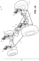
- FIG. 1A a perspective view of a vehicle 50 with a plug and play suspension system 75 having at least one system on a shock assembly 38 is shown in accordance with an embodiment.
- the plug and play suspension system 75 having at least one system on a shock assembly 38 disclosed herein is also suited for use in other vehicles such as, but not limited to a bicycle, an electric bike (e-bike), a hybrid bike, a scooter, a motorcycle, an ATV, a personal water craft (PWC), a vehicle with three or more wheels (e.g., a UTV such as a side-by-side, a car, truck, etc.), an aircraft, and the like.
- a bicycle an electric bike (e-bike), a hybrid bike, a scooter, a motorcycle, an ATV, a personal water craft (PWC), a vehicle with three or more wheels (e.g., a UTV such as a side-by-side, a car, truck, etc.), an aircraft, and the like.
- e-bike electric bike
- the plug and play suspension system 75 having at least one system on a shock assembly 38 is also suited for use in suspension inclusive devices such as, but not limited to, an exoskeleton, a seat frame, a prosthetic, a suspended floor, and the like.
- suspension inclusive devices such as, but not limited to, an exoskeleton, a seat frame, a prosthetic, a suspended floor, and the like.
- a 4-wheeled vehicle 50 is utilized as the example vehicle upon which the plug and play suspension having at least one system on a shock assembly 38 is shown and descri bed.
- vehicle 50 is a generic vehicle such as a car, truck, side-by-side, or the like driven by an engine and consisting of an unsprung portion (such as tires 32, drive train 37, axles, etc.), a sprung portion (such as a cockpit, seating area, etc.), and a plug and play suspension system 75 includes at least one system on a shock assembly 38 to couple the sprung portion of the vehicle with the unsprung portion.
- an unsprung portion such as tires 32, drive train 37, axles, etc.
- a sprung portion such as a cockpit, seating area, etc.
- plug and play suspension system 75 includes at least one system on a shock assembly 38 to couple the sprung portion of the vehicle with the unsprung portion.
- vehicle 50 can include one or more electronically actuated components, interactive components, and/or control features such as for example, a user interface 205, active and/or semi-active system on a shock assemblies 38, vehicle dynamic module (VDM) 21, one or more devices 12 (such as sensor or the like), a power source, smart components, and the like.
- VDM vehicle dynamic module
- the one or more sensor(s) could be used to monitor and/or measure things such as temperature, voltage, current, resistance, noise (such as when a motor is actuated, fluid flow through a flow path, engine knocks, pings, etc.), positions of one or more components of vehicle 50 (e.g., shock positions, ride height, pitch, yaw, roll, etc.), and the like.
- the one or more sensor(s) could be forward looking terrain, vibrations, bump, impact event, angular measurements, and the like.
- plug and play suspension system 75 includes one or more electronically actuated components, interactive components, and/or control features.
- plug and play suspension system 75 includes at least one system on a shock assembly 38, and a communications network 5.
- plug and play suspension system 75 also optionally utilizes a power source 78, and optionally communicates with none, one, some or all of a user interface 205 (or controller), external on-vehicle devices 12 (such as sensor or the like), the vehicle ECU 80, and one or more off-vehicle devices 129.
- an off-vehicle device 129 could be, for example, a trailer being towed.
- system on a shock assemblies (and/or other interactive components) of the trailer can be added to the communications network 5.
- the communications network 5 could expand to the tow vehicle, the trailer, and the side-by-side such that the system on a shock assemblies (and/or other interactive components) on each of the vehicles would be able to work in conjunction.
- the tow vehicle hits bump
- the information is passed to the trailer suspension which would be prepped for the event impact
- the information is also passed to the side-by-side, such that the side-by-side's suspension is adjusted to provide better interaction between the side-by-side and the trailer as the impact event is encountered by the trailer.
- an off-vehicle device 129 could be, for example, components of a second plug and play suspension system (such as located on another vehicle, a suspension inclusive devices such as, but not limited to, an exoskeleton, a seat frame, a prosthetic, a suspended floor, and the like).
- components of the second plug and play suspension system can be added to the communications network 5 such that the plug and play suspension systems would be able to work in conjunction. For example, if the first plug and play suspension system encounters an event such as a dip ahead of the second plug and play suspension system. The event information is passed to the second trailing plug and play suspension system which would be able to prepare one or more components of the plug and play suspension system for the event encounter.
- plug and play suspension system 75 can include suspension components such as sway bars, and the like.
- suspension components such as sway bars, and the like.
- one or a plurality of other component(s) of vehicle 50 are also smart component(s).
- the smart component(s) will include connective features that allow them to communicate wired or wirelessly with one or more of the electronically actuated components, interactive components, control features, and/or the like of plug and play suspension system 75.
- data is collected or provided from the smart component(s), electronically actuated components, interactive components, control features, and/or the like to one or more components of the plug and play suspension system 75.
- the data may be location data, sensor data, telemetry data, and the like.
- telemetry data can include data such as angle, orientation, velocity, acceleration, RPM, operating temperature, and the like.
- plug and play suspension system 75 can include all of the components shown in the schematic diagram of Figure 1B . In one embodiment, by eliminating harnesses and external components, cost and complexity of the plug and play suspension system 75 is reduced while durability is improved, as compared to existing suspension systems.
- plug and play suspension system 75 would include some of the components shown in the schematic diagram of Figure 1B .
- a partial plug and play suspension system 75 might include at least one system on a shock assembly 38 (although all of the shock assemblies on the vehicle 50 might not be system on a shock assemblies 38, some might be standard shock assemblies, active shock assemblies, a combination thereof, or the like), communications network 5, and optionally user interface 205.
- plug and play suspension system 75 will only include a limited number of the system on a shock assemblies 38 shown in the schematic diagram of Figure 1B .
- a plug and play suspension system 75 might only include one or more system on a shock assemblies 38.
- communication network 5 is a stand-alone communications network. That is, instead of utilizing existing vehicle wiring harness or communications systems, the communication network 5 will be specifically designed for use with the plug and play suspension system 75. Thus, in one embodiment, the installation of plug and play suspension system 75 will not require any tapping into existing vehicle wiring.
- communication network 5 may provide communication with one or some components of the vehicle such as an In-Vehicle Infotainment (IVI), external on vehicle devices 12, the vehicle ECU 80, off-vehicle device 129, or the like.
- IVI In-Vehicle Infotainment
- the components of plug and play suspension system 75 are not required to be added to or connected with, the main vehicle wiring harness.
- the components of plug and play suspension system 75 do not require connectivity with the vehicle CAN bus (or ECU 80) to connect, access, control, monitor, adjust, modify, receive feedback, communicate or otherwise operate within the parameters of the vehicle 50 upon which they are installed.
- the components of plug and play suspension system 75 are added to the vehicle and use their own communications network 5 to act as separately controlled items to monitor/adjust/modify or otherwise control the performance characteristics thereof.
- the plug and play suspension system 75 provides a plug and play capability such that one or more component are removed, replaced, added, or the like, to the plug and play suspension system 75 by adding the component to (or removing the component from) the vehicle 50 and then providing the component with access to (or removing the component's access from) the communication network 5.
- the component when a component is added to the plug and play suspension system 75 such that it has access to some, part, or all of the communications network 5, the component may be assigned its function and/or roll in the suspension system by one or more other components of plug and play suspension system 75.
- the component when a component is added to the plug and play suspension system 75 such that it has access to some, part, or all of the communications network 5, the component may automatically recognize or determine its function and/or roll in the suspension system. In one embodiment, when an added component automatically recognizes or determines its function and/or roll in the suspension system, the added component will use communications network 5 to broadcast that information to one or more other components of plug and play suspension system 75 (and/or other components, systems, or the like in communication with plug and play suspension system 75).
- components of plug and play suspension system 75 are added wired/wirelessly or a combination thereof as a none-to-node communications network 5. In one embodiment, they are added wired/wirelessly or a combination thereof as a spoke communications network 5. In one embodiment, they are added wired/wirelessly or a combination thereof as a hybrid communications network 5 that would include both node-to-node communications network 5 and spoke communications network 5 configurations.
- the systems on a shock assembly 38 may communicate with a vehicle ECU 80 via the vehicle CAN bus (or user interface 205, or the like) to provide sensor and/or performance information that can be used by the vehicle ECU 80 for vehicle performance information such as antilock braking, sway information, drift information, wheel spin information, ride height information, and/or data from other on-vehicle device(s) 12 that may be utilized by the vehicle ECU 80.
- vehicle performance information such as antilock braking, sway information, drift information, wheel spin information, ride height information, and/or data from other on-vehicle device(s) 12 that may be utilized by the vehicle ECU 80.
- communication network 5 is a wired communication network 5 (such as via a wiring harness or the like).
- power for one or more of the components of plug and play suspension system 75 is received over a wired connection.
- the motive component such as a solenoid, stepper motor, electric motor, or the like that operates the valving in one or more system on a shock assemblies 38 would receive its power from a power source 78 coupled with the wiring harness (e.g., the vehicle battery, alternator, a power supply incorporated with user interface 205, a power supply coupled with another of the one or more system on a shock assemblies 38, a reserve or extra power supply for auxiliary components, or the like).
- one, some, or all of the components shown in Figures 1A and/or 1B could be located in other locations.
- one, some, or all of the components could be located on the sides of components, at the handlebars, at a foot peg (or footwell), carried by the rider if it is wireless, located on a mount attached to a portion of the vehicle 50, etc.
- the use of the locations of components as shown in Figures 1A and 1B are indicative of one embodiment, which is provided for purposes of clarity.
- communication network 5 is a wireless communication network.
- one or more system on a shock assemblies 38 will be in wireless communication with one or more other system on a shock assemblies 38, the user interface 205 (and/or VDM 21, vehicle devices 12 (such as sensor or the like), or other components such as, but not limited to, those shown in Figure 1B ) without requiring a wiring harness.
- one or more system on a shock assemblies 38 will include its own power source 595 and the actuator(s) (e.g., motive component such as a solenoid, stepper motor, electric motor, or the like) that operates the active valve would receive its operating power therefrom.
- the actuator(s) e.g., motive component such as a solenoid, stepper motor, electric motor, or the like
- one or more of the system on a shock assemblies 38 would be a self-contained unit which would be able to perform an adjustment to at least one performance characteristic of the system on a shock assembly 38.
- the adjustment may be generated by the on-shock ECU 596 as described herein.
- the adjustment may be received vie the communications network 5 from another component such as user interface 205, an off-vehicle device 129, or the like.
- communication network 5 is a combination of wired and wireless connectivity.
- communication network 5 is a hub-spoke communications network.
- a spoke-type communications network 5 configuration one or more of the components of plug and play suspension system 75 would communicate with a main control component such as VDM 21, user interface 205, or the like. The main control component would then be used to manage the components and performance of plug and play suspension system 75.
- one of the systems on a shock assemblies 38 would be designated as the hub component.
- the designated systems on a shock assembly 38 hub component would then be used to manage the components and performance of plug and play suspension system 75.
- communication network 5 is a node-to-node communications network.
- each of the systems on a shock assemblies 38 would communicate wired/wirelessly with each other and optionally with a main control component.
- one, some, or all of the systems on a shock assemblies 38 and the optional main control component would be communicatively coupled (wired and/or wirelessly) with the user interface 205 (such as IVI, infotainment, mobile devices and applications), other peripheral devices, and optionally the vehicle ECU 80, off-vehicle device 129, or the like.
- each of the system on a shock assemblies 38 would communicate wired/wirelessly with each other.
- one, some, or all of the system on a shock assemblies 38 would also be communicatively coupled (wired and/or wirelessly) with the user interface 205 (such as IVI, infotainment, mobile devices and applications), other peripheral devices, and optionally the vehicle ECU 80, off-vehicle device 129, or the like.
- communication network 5 is a hybrid communications network of wired and wireless connectivity.
- each of the components of plug and play suspension system 75 would communicate wired/wirelessly with each other and with a main control component.
- the main control component would be communicatively coupled (wired and/or wirelessly) with the user interface 205 (such as IVI, infotainment, mobile devices and applications), other peripheral devices, and optionally the vehicle ECU 80, off-vehicle device 129, or the like.
- each of the components of plug and play suspension system 75 would communicate wired/wirelessly with each other and with a main control component.
- one, some, or all of the systems on a shock assembly 38 and/or the main control component would be communicatively coupled (wired and/or wirelessly) with the user interface 205 (such as IVI, infotainment, mobile devices and applications), other peripheral devices, and optionally the vehicle ECU 80, off-vehicle device 129, or the like.
- each of the components of plug and play suspension system 75 would communicate wired/wirelessly with each other.
- one, some, or all of the systems on a shock assembly 38 would also be communicatively coupled (wired and/or wirelessly) with the user interface 205 (such as IVI, infotainment, mobile devices and applications), other peripheral devices, and optionally the vehicle ECU 80, off-vehicle device 129, or the like.
- one or more system on a shock assemblies 38 would be in wireless communication with user interface 205 (such as IVI, infotainment, mobile devices and applications), other peripheral devices, and optionally the vehicle ECU 80, off-vehicle device 129, or the like, and any shock assembly adjustment inputs received at the one or more system on a shock assemblies 38 (e.g., the changing of the rebound tunes, compression tunes, lockout, or the like) would be received wirelessly.
- the actuators 99 (or other motive component such as a solenoid, stepper motor, electric motor, or the like) of the system on a shock assembly 38 would receive power from power source 78 via a wired connection with the vehicle battery, a power supply incorporated with user interface 205, a power supply coupled with any of the other system on a shock assemblies 38, a reserve or extra power supply for auxiliary components, or the like.
- system on a shock assembly 38 would include its own power source (such as power source 595 shown in Figure 3 ) and the actuators 99 (or other motive component such as a solenoid, stepper motor, electric motor, or the like) of the system on a shock assembly 38 would receive their operating power therefrom.
- power source 595 shown in Figure 3 the actuators 99 (or other motive component such as a solenoid, stepper motor, electric motor, or the like) of the system on a shock assembly 38 would receive their operating power therefrom.
- system on a shock assembly 38 includes a number of components such as a PCB 596 and actuator 99.
- PCB 596 is an ECU including one or more components such as internal sensors 331, a power source 595, a microcontroller 73, and motor controller 74.
- system on a shock assembly 38 includes a plurality of electronics coupled therewith to collect data, actuate mechanisms, and communicate with external devices through wired and wireless protocols.
- the electronic devices can include Master ECU, other shock-electronic-assemblies, HMIs, IMUs, and other sensors.
- internal sensors 331 may be one or more sensor(s) to monitor and/or measure things such as temperature, voltage, current, resistance, noise (such as when a motor is actuated, fluid flow through a flow path, engine knocks, pings, etc.), positions of one or more components of vehicle 50 such as, system on a shock assembly 38 settings (such as preload, compression settings, rebound settings, lockout, or the like) ride height, pitch, yaw, roll, and the like.
- the one or more sensor(s) could be forward looking terrain sensors, vibration sensors, bump sensors, impact event sensors, angular measurements sensors, and the like. Additional information about sensors, other sensor types, and their operations are provided in U.S. Patents 8,838,335 ; 9,353,818 ; 9,682,604 ; 9,797,467 ; 10,036,443 ; 10,415,662 to which reference is specifically made.
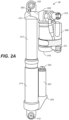
- the system on a shock assembly 38 is a FOX load optimizing air technology (FLOAT) air shock assembly with a reservoir 316.
- FLOAT FOX load optimizing air technology
- the air shock assembly is a high-performance shock assembly that use air as springs, instead of heavy steel coil springs or expensive titanium coil springs.
- system on a shock assembly 38 includes attachment features such as, in one embodiment, a chassis mount (e.g., upper eyelet 105) and a rear suspension mount (e.g., lower eyelet 110) which allow system on a shock assembly 38 to be coupled between the sprung and unsprung portion of vehicle 50.
- a chassis mount e.g., upper eyelet 105
- a rear suspension mount e.g., lower eyelet 110
- system on a shock assembly 38 includes body 312, an expansion component (e.g., main air chamber 314) providing some type of expansive (or spring) force on system on a shock assembly 38, and a main air valve 324 for adding or removing air from main air chamber 314.
- the system on a shock assembly 38 also includes body cap 310, and a reservoir 316 fluidly coupled with the body 312.
- system on a shock assembly 38 includes one or more electronically adjustable valves such as an electronically adjustable rebound damping valve 393, an electronic valve 500, and the like.
- system on a shock assembly 38 includes a main chamber within body 312 that holds the working fluid and a main damping piston.
- system on a shock assembly 38 includes a body cap 310 with a flow path therein fluidly coupling the main chamber within body 312 with a reservoir chamber of reservoir 316.
- the electronic valve 500 is used to modify and/or control the flow rate of the working fluid through the flow path.
- system on a shock assembly 38 includes an expansion component (e.g., main air chamber 314) used to provide some type of expansive (or spring) force to system on a shock assembly 38, a main air valve 324 for adding or removing air from main air chamber 314, and a piston coupled with a piston shaft, where the piston is located somewhere within the internal chamber of body 312.
- expansion component e.g., main air chamber 314 used to provide some type of expansive (or spring) force to system on a shock assembly 38
- main air valve 324 for adding or removing air from main air chamber 314, and a piston coupled with a piston shaft, where the piston is located somewhere within the internal chamber of body 312.
- the resting length of system on a shock assembly 38 when installed, the resting length of system on a shock assembly 38 is maintained in compression by the weight of the body it is suspending (e.g., the sprung portion of vehicle 50), and in expansion by the "spring" force produced by the expansion component (e.g., the main air chamber 314).
- reservoir 316 is fluidly coupled with the body 312 via a flow path(s) through body cap 310.
- the reservoir 316 has a reservoir chamber that is divided by an internal floating piston (IFP).
- IFP internal floating piston
- one side of the IFP divided reservoir chamber is filled with a pressurized gas (e.g., nitrogen, or the like) and the other side of reservoir chamber is fluidly coupled with the main chamber of body 312 via flow path 404 and contains working fluid.
- a pressurized gas e.g., nitrogen, or the like
- the IFP keeps the pressurized gas from mixing with the working fluid and/or reaching the flow path.
- system on a shock assembly 38 is compressed causing the piston and piston shaft to move further into the main chamber of body 312 (e.g., the compression stroke).
- the expansion component e.g., main air chamber 314 which was compressed by body 312 moving thereinto, acts to push body 312 back out of the main air chamber 314, causing the piston and piston shaft to move back toward their original location within the chamber of body 312 (e.g., the rebound stroke).
- system on a shock assembly 38 includes an optional extra volume (Evol) chamber 322 with an Evol air valve 320 (similar in function to main air valve 324 described herein).
- the Evol chamber 322 allows the available air volume of main air chamber 314 of system on a shock assembly 38 to be changed on the fly, e.g., while the vehicle is in operation.
- the change in available air volume is controlled by a user providing an input electronically over a wired or wireless connection with user interface 205.
- the change is automatically provided by an input from a control system on or connected with the vehicle such as VDM 21.
- the change is automatically provided by an input from microcontroller 73 located on PCB 596.
- the change to the air volume can be controlled by an automated system (e.g., microcontroller 73, VDM 21, or the like), while also receiving control inputs from the user via user interface 205.
- the air spring style system on a shock assembly 38 is lightweight and progressive.
- the progressive aspect occurs during the increase in spring force and travel.
- the spring force increase is provided by the body 312 reducing the volume of the main air chamber 314 which compresses the air therein.
- the Evol chamber can be used to add to the spring force increase being generated by the additional compression of the air in the main air chamber 314.
- main air chamber 314 and Evol chamber 322 are separated, they can be independently tuned. However, since they also work together in the described progressive fashion, the range of the combined tuning is greater than that of either alone. Thereby providing adjustability for performance across a wide variety of terrain, riding style, and user weights.
- adjusting the pressure in the main air chamber 314 is similar to changing a tender, and/or secondary springs, and/or the crossover spacers on a coil-over shock.
- adjusting the pressure in the main air chamber 314 will adjust ride height.
- adjusting the pressure in the Evol chamber 322 is similar to changing a main spring on a coil-over shock, that is, it will help control bottom out and chassis roll.
- system on a shock assembly 38 shown is an air shock style shock assembly
- system on a shock assembly 38 may also be a coil-over shock assembly, such as, for example, a FOX 2.0 zero QS3-R shock assembly with a velocity-sensitive shimmed damping system, one or more coil-over springs, a spring preload adjuster, and a reservoir.
- the system on a shock assembly 38 may be another type of shock assembly such as, but not limited to, a stand-alone fluid damper assembly, a coil sprung adjustable shock assembly, an air sprung fluid damper assembly, or the like.
- system on a shock assembly 38 includes a transmitter/receiver 420 which receives data transmissions via communications network 5.
- system on a shock assembly 38 use a communication protocol such as, but not limited to, those disclosed in the communication protocol section herein.
- system on a shock assembly 38 uses small and light electronic componentry with a focus on both the minimizing of power requirements resulting in a long battery life and the minimizing of the weight/rotational inertia of the actuator 99.
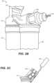
- system on a shock assembly 38 includes a wire 410 extending therefrom.
- the wire 410 provides the wired connection with communications network 5 (and one or more of the other components of plug and play suspension system 75).
- wire 410 of Figure 2B is coupled with a transmitter/receiver 420 and PCB 596 (which in one embodiment includes power source 595, microcontroller 73, motor controller 74, sensor 331) in accordance with an embodiment.
- FIG. 3 a cut-away view of a portion of system on a shock assembly 38 with electronic valve 500, a power source 595, a PCB 596 (which in one embodiment includes microcontroller 73, motor controller 74, sensor 331), and transmitter/receiver 420 are shown in accordance with an embodiment.
- the control process utilizes the wireless radio (at the user interface 205), a microcontroller 73 and a motor controller 74 (in one embodiment, both the microcontroller and the motor controller are located closer (if not physically coupled with) actuator 99).
- microcontroller and motor controller are located on the same PCB 596.
- the wireless radio senses an actuation signal from the trigger unit e.g., the user interacts with user interface 205 to indicate a desired change to the shock assembly tune.
- the microcontroller 73 sends a signal to the motor controller 74.
- the motor controller allows power from the power source (such as 595 or the like) to be applied to the actuator 99.
- full voltage from the power source is supplied to the actuator 99. In one embodiment, full voltage from the power source is supplied such that the actuator 99 is spun as quickly as possible. In one embodiment, less than full voltage from the power source is supplied to the actuator 99.
- one or more components of the control process e.g., microcontroller, motor controller, or the like
- monitor for a condition that occurs during the operation of actuator 99 e.g., current, proxy current, time, resistance, voltage, temperature, other sensors input, or the like
- the condition is met, the power to actuator 99 is removed.
- the motor controller 74 senses the current provided to actuator 99 using a circuit integrated into the motor controller 74.
- the current or other measurable aspect
- the operating current provided to actuator 99 is compared to one or more predetermined values (or current thresholds) stored in the memory of the microcontroller 73.
- the microcontroller 73 when the sensed current meets the predetermined threshold (e.g., a current threshold that represents actuator 99 stall), the microcontroller 73 sends a signal to the motor controller 74 to shut off the power to the actuator 99. In one embodiment, this would complete a "closed” portion of the control strategy (e.g., closing the electronic valve 500) and lockout the system on a shock assembly 38.
- the predetermined threshold e.g., a current threshold that represents actuator 99 stall
- the reverse operation occurs to open electronic valve 500. That is, the wireless radio receives the data.
- the microcontroller 73 sends a signal to the motor controller 74 to once again allow power to be provided to the actuator 99, (however, in one embodiment, it is provided in an opposite polarity from that provided in the electronic valve 500 close operation to cause the actuator 99 to rotate in the opposite direction).
- the current is sensed until the current threshold criteria is met, at which point the microcontroller 73 sends a signal to the motor controller 74 to shut off the power to actuator 99. In one embodiment, this would complete the "unlock" portion of the control strategy (e.g., opening the electronic valve 500).
- the use of the control process described herein to monitor and analyze the sensed current greatly reduces the complexity associated with the opening and closing of conventional electronically-actuated valves.
- only two wires are required to be coupled to actuator 99.
- the two wires provide the power to actuator 99, (e.g., completing a circuit between the power source 595 and actuator 99).
- the microcontroller 73 and/or motor controller 74 would also be included in the circuit to control the flow of power from the power source 595 to actuator 99.
- the current (or other measurable aspect) can be sensed at any desired location of the circuit.
- the current may be sensed at, but not limited to, any of the following locations, at or very near actuator 99, at a location remote from actuator 99, at the same location as the power source 595, at a control unit (such as microcontroller 73 and/or motor controller 74), and the like.
- a condition e.g., current, proxy current, time, resistance, voltage, temperature, other sensors input, or the like
- a timer or the like could be used to control the time the power is supplied to actuator 99. For example, if actuator 99 spins at a rate of 200 rpm and the electronic valve 500 needs to be rotated 180 degrees, then the timer would let the actuator 99 operate for 0.15 seconds.
- the timer and/or filters disclosed herein could also be used as back-up or confirmation settings to ensure against faults/transients such as where the stall current threshold is reached before the electronic valve 500 is completely open or completely closed. Thus, using any and/or all of these methods, there is no need to measure the position of the actuator 99 directly.
- electronic valve 500 is (effectively) a two-state valve. In other words, the electronic valve 500 is either open or closed.
- the electronic valve 500 may have intermediate states (to limit flow, such as a high flow, a medium flow, a slow flow, etc., but not at zero flow).
- there may be a control system an encoder on actuator 99 with different settings thereon, etc. to control/adjust the orifice size of electronic valve 500 into one or more intermediate states, (e.g., between on and off), to provide a regulated flow.
- electronic valve 500 could be a multi-state rotary spool valve having a number of intermediate states (to limit flow, such as a high flow, a medium flow, a slow flow, etc.) between the closed state and the full-open state.
- the multi-state rotary spool electronic valve 500 would include one or more intermediate settings in addition to the softest and the lockout positions to control flow.
- multi-state rotary spool electronic valve 500 would have a firmness range that becomes increasingly firmer as the multi-state rotary spool is rotated from the soft setting to the lockout setting.
- soft setting feature is on one end stop and lockout setting feature is on another end stop.
- soft setting feature and lockout setting feature are set 150 degrees apart. In another embodiment, they may be set at a different range. The use of 150 degrees is one embodiment and provided for purposes of clarity in the following examples.
- the motor controller 74 may overshoot to each end stop to change between the soft setting and lockout setting of multi-state rotary spool electronic valve 500 using the control and operation description provided in the discussion of Figure 3 .
- other measuring devices such as timers, filters, thermometer, other sensors, and the like, may be used to measure time, resistance, voltage, temperature, noise, or the like.
- the control process is looking for a condition (e.g., current, proxy current, time, resistance, voltage, temperature, other sensors input, or the like) supplied to the actuator 99 that satisfies a predetermined criteria.
- a timer is used to time the operation of the actuator 99 such that it moves approximately half way between the soft setting and lockout setting. For example, if a rotational rate for a given power of actuator 99 is known, and the amount of desired rotation of the multi-state rotary spool electronic valve 500 is also known, a timer or the like could be used to control the time the power is supplied to actuator 99. For example, if actuator 99 spins at a rate of 200 rpm and the multi-state rotary spool electronic valve 500 needs to be rotated approximately 75 degrees, then the timer would let the actuator 99 operate for 0.06 seconds.
- the microcontroller/Radio is a Feather MO with RFM69HCW packet radio (433 MHz).
- the motor controller is a DRV8833 2 channel controller with current limiting capabilities.
- the user interface 205 microcontroller/Radio is a Feather M0 with RFM69HCW packet radio (433 MHz).
- user interface 205 includes a voltage regulator such as TSR-12450.
- the buttons on user interface 205 are momentary switches.
- the user interface 205 is a touchpoint interface 205a.
- the user interface 205 is a mobile device 205b.
- the user interface 205 is an IVI interface 205c.
- the user interface 205 is a button/switch type interface 205d.
- user interface 205 is provided in a location convenient for user manipulation during vehicle operation.
- user interface 205 is provided in the cockpit of vehicle 50 (or other part of vehicle 50 that is user accessible during vehicle operation).
- button/switch type interface 205d is coupled with a vehicle component via a clip or other retaining device.
- user interface may be part of an IVI interface 205c or mobile device 205b that is user interactive and may include features such as, but not limited to, voice activation/control, location derivation capabilities (e.g., a GPS device or the like), one or more applications operating thereon, a switch (or lever, button, etc.) or the like.
- the user interface 205 could be located at another portion of the vehicle, on a mount coupled with the vehicle, worn as a smart device, carried by the rider, or the like.
- the user interactive system will provide feedback, command, and/or control capabilities for one or more aspects such as shock performance, stiffness, preload, rebound adjustment, compression adjustment, and/or overall vehicle suspension configurations.
- the control capabilities could be programmable, modifiable, and/or adjustable in real-time by a user input.
- the user input adjustments could be based on aspects such as, but not limited to, pre-defined times, location(s), terrain type, weather, suspension performance data, shock assembly performance data, sensor data, information received from another source, information from other components coupled with the vehicle such as the vehicle can bus, cameras, sensors, monitors, and the like.
- control capabilities could be automatically switched to a different tune, automatically modified, and/or automatically adjusted based on aspects such as, but not limited to, pre-defined times, location(s), distance traveled, terrain type, weather, suspension performance data, shock assembly performance data, sensor data, information received from another source, information from other components coupled with the vehicle such as the vehicle can bus, cameras, sensors, monitors, and the like.
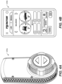
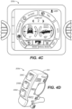
- user interface 205 will be described in conjunction with user interface 205d of Figure 4D .
- similar operation of and interaction between user interface 205 and the one or more system on a shock assemblies 38 of the plug and play suspension system 75 are available in different formats depending upon the different type of user interface 205.
- a signal is sent from the user interface 205 to one or more system on a shock assemblies 38.
- communications component 220 will provide wireless communications between the user interface 205 and the system on a shock assembly 38. In one embodiment, communications component 220 will provide a wired communication between the user interface 205 and the system on a shock assembly 38.
- user interface 205d includes a number of buttons 206A-206C. Although three buttons are shown, this is indicative of one embodiment and is shown for purposes of clarity.
- user interface 205 stores one or more programable (or preset) shock assembly settings (or tunes) that, when selected, cause one or more characteristics of one or more system on a shock assemblies 38 to be changed on the fly.
- a different tune is selected by each of the three buttons, e.g., buttons 206A-206C.
- different tunes provide different performance characteristics for the system on a shock assembly 38.
- the different tunes can make large, medium, and/or small changes to the characteristics of the system on a shock assembly 38.
- one tune might be a softest performance setting, while another tune is a lockout setting.
- button 206A would be a soft mode, e.g., a tune designed for maximum comfort.
- button 206B would provide another tune such as a middle mode (e.g., a tune designed for balanced all-around performance), a firm mode (e.g., a shock assembly tune designed for aggressive trail riding, increased load carrying capacity, etc.), or the like.
- button 206C would cause the lockout to be engaged (or disengaged).
- user interface 205 may have any number of screen selectable options, buttons, switches, levers, dials, or the like, each of which could also have one or more tunes associated therewith.
- the user interface 205 may be integrated with the vehicle structure, suspension components, suspension component controller(s) and data processing system as described in U.S. Pat. Nos. 7,484,603 ; 8,838,335 ; 8,955,653 ; 9,303,712 ; 10,060,499 ; 10,443,671 ; 10,737,546 ; and 10,933,710 the content of each of which are incorporated by reference herein, in their entirety.
- plug and play suspension system 75 when plug and play suspension system 75 includes a plurality of system on a shock assemblies 38, the adjustments provided by user interface 205 could be the same, or different for one or more of the different system on a shock assemblies 38. Moreover, it should be appreciated that if less than all four shock assemblies are system on a shock assemblies 38, the above example, would be similarly applied to the active shock assemblies of the system.
- a user (and/or manufacturer, after market provider, suspension tuner, mechanic, etc.) would be able to set up the same or different configurations for one or more of the system on a shock assemblies 38 for each tune.
- the differences could be due to user skill, terrain type, ride format (e.g., work, fun, race, thrill, extreme, etc.), loaded weight, altitude, temperature, etc.
- the different tunes can be predefined for a given vehicle to cover different performance characteristics such as, but not limited to, smooth ride, fast ride, bumpy ride, hill climb, hill descent, and the like.
- the different tunes may be modified by the user for more personalized performance based on aspects such as, but not limited to user skill, user body type, the vehicle, components on the vehicle, other suspension settings on the vehicle, location of operation, terrain type, weather, temperature, etc.
- the tunes may be downloaded from a user's computer, mobile device, etc.
- the tunes may be obtained via a suspension tune application, library, or the like as described in U.S. Patent 11,459,050 , which is incorporated herein by reference in its entirety.
- one power source could be used to power a plurality of components of plug and play suspension system 75.
- power source 78 may be used as a power source for one, some, or all of the plug and play suspension system 75 components.
- one power source could be used to power some of the plurality of components of plug and play suspension system 75, while other of the components of plug and play suspension system 75 would have their own power source 595.
- power source 78 may be used as a power source for a plurality of components such as any combination of one or more of the user interface 205, system on a shock assemblies 38, one or more sensor(s) 331, smart components, and the like. While the remaining one or more of the user interface 205, system on a shock assemblies 38, one or more sensor(s) 331, smart components, and the like would each have their own power source.
- each of the user interface 205, system on a shock assemblies 38, one or more sensor(s) 331, smart components, and the like, would have its own power source.
- user interface 205 and at least one system on a shock assembly 38 would share a power source.
- the power source is integrated with a component, and as such, is not easily or readily removable without some amount of disassembly.
- the power source may be integrated into user interface 205, system on a shock assemblies 38, one or more sensor(s) 331, smart components, and the like.
- the power source would either have to be replaced during a disassembly procedure, be designed to last for a given amount of time, be wired or wirelessly rechargeable in place, or the like.
- the component might have a charging port that allows a charger to connect with the power source integrated therein.
- the power source is removably coupled with one or more components such that it can be removed, replaced, or the like.
- the power source would be located in an accessible location, such as inside a protective cover or in a housing such as on one or more of the user interface 205, system on a shock assemblies 38, one or more sensor(s) 331, smart components, and the like.
- the power source can be removed by a user for replacement, storage, charging, security (e.g., so it is not stolen), and the like.
- one or more power sources may be externally mounted on the frame and/or one or more other components of the vehicle.
- the power source could be externally mounted such that it is easily and/or quickly removable for charging, replacement, storage, and/or security.
- the power source could be externally mounted such that it is not easily and/or quickly removable for charging, replacement, storage, and/or security.
- one or more power sources may be internally mounted on the frame and/or one or more other components of the vehicle.
- the power source could be internally mounted such that it is easily and/or quickly removable for charging, replacement, storage, and/or security.
- the power source could be internally mounted such that it is not easily and/or quickly removable for charging, replacement, storage, and/or security.
- the power source could be a power source that is not dedicated to any of the components discussed herein.
- power source 78 is the main battery (or a power source for a light, for controlling a suspension state (e.g., raising or lowering the starting point of a front shock, raising or lowering the starting point of a rear shock), for a vehicle display (such as an IVI), for an electronic transmission, starter, seat warmer, etc.) it would have a primary functionality of providing power to the vehicle (or other component). As such, it may not be considered a dedicated battery for any other components.
- the main battery may be used as a power source for one, some, or all of the user interface 205, system on a shock assemblies 38, one or more sensor(s) 331, smart components, and the like.
- the power source is comprised of a power station or power pack.
- the power source is a non-rechargeable battery such as, but not limited to, one or more of a CR2032 battery, a double A battery, a triple A battery, a lithium coin cell battery, a silver oxide cell battery, or the like.
- the power source is a rechargeable battery such as, but not limited to, a lithium-ion battery.
- the power source can be recharged wired or wirelessly.
- a power source having a wirelessly rechargeable capability means it could be charged using a wireless power transfer system. E.g., using an inductive charger (or the like) within a given distance of the wirelessly rechargeable capability of the power source.
- Wireless charging in its most basic form utilizes a copper coil to create an oscillating magnetic field, which can create a current in one or more receiver antennas.
- the wireless charger could be a charging pad that use tightly-coupled electromagnetic inductive or non-radiative charging;
- a charging bowl or through-surface type charger that uses loosely-coupled or radiative electromagnetic resonant charging to transmit a charge a few inches;
- An uncoupled radio frequency wireless charger that allows a trickle charging capability at distances of many feet, or the like.
- Examples of a wireless power transfer systems that could be used in one or more embodiments include those defined by the wireless power consortium (WPC) Qi standard, the AirFuel Alliance (e.g., Duracell Powermat, PowerKiss, etc.), WiTricity, Cota TM real wireless power, and the like.
- WPC wireless power consortium
- AirFuel Alliance e.g., Duracell Powermat, PowerKiss, etc.
- WiTricity e.g., WiTricity, Cota TM real wireless power, and the like.
- the power source can be charged even though if it is sealed within a component. In one embodiment, the power source can be charged while the component is installed on the vehicle 50. In one embodiment, the wireless power transfer capability is dependent upon factors such as, material type (e.g., composite, metal, thin, thick, etc.), the type of wireless power transfer being used, etc.
- the power source is an energy harvesting switch that does not require a battery or other powered connection.
- the energy harvesting switch is capable of operating for an indefinite amount of time without requiring any type of recharge, battery change, etc.
- the energy harvesting switch utilizes a momentary generator such as ZF electronics AFIG-0007 to provide power.
- the power source is a combination or hybridization of two or more of the replaceable battery, the rechargeable battery, the energy harvesting switch, and the like.
- the various power source location and/or configuration embodiments described herein eliminate the need for a user/rider to keep track of, or otherwise monitor, the power level of the power source at the component being powered. Instead, the user/rider is able to remove and "plug in" the power source, for example, after use of the vehicle and the power source will be fully recharged. Upon recharging, the power source is replaced on the vehicle, and the rider/user is assured that ample power will be provided to the component (or components being powered), E.g., user interface 205, system on a shock assemblies 38, one or more sensor(s) 331, smart components, and the like.
- one, some, or all of the user interface 205, system on a shock assemblies 38, one or more sensor(s) 331, smart components, and the like have wired and/or wireless communication capabilities.
- the wireless communications network 5 is selected from one or more of: a wireless personal area network (WPAN), a low power network (LPAN), Internet of things (IoT) connectivity, or the like.
- the wireless communication protocol could be, but is not limited to, Bluetooth, WiFi, Bluetooth Low Energy (BLE), near field communication (NFC), UHF radio signal, Worldwide Interoperability for Microwave Access (WiMax), long-term evolution (LTE), industrial, scientific, and medical (ISM) band, IEEE 802.15.4 standard communicators, Zigbee, ANT, ISA100.11a (wireless systems for industrial automation: process control and related applications) wireless highway addressable remote transducer protocol (HART), MiWi, IPv6 over low-power wireless personal area networks (6LoWPAN), thread network protocol, subnetwork access protocol (SNAP), and the like.
- Bluetooth Bluetooth, WiFi, Bluetooth Low Energy (BLE), near field communication (NFC), UHF radio signal, Worldwide Interoperability for Microwave Access (WiMax), long-term evolution (L
- one, some, or all of the user interface 205, system on a shock assemblies 38, one or more sensor(s) 331, smart components, and the like could form a wireless mesh communications network 5, such as a vehicle area network (VAN) or the like.
- VAN vehicle area network
- one or more components of the VAN could interact with the user/rider in any number of ways such as via touch, sound, vision, radio, wearable, and the like.
- the components within the communications network 5 may include an auxiliary or propriety private network encryption such as AES 128.
- the AES-128 block cipher is operated in the Authenticated Encryption with Associated Data (AEAD) scheme, which allows encrypting the given plaintext, and authenticating associated plain text data.
- AEAD Authenticated Encryption with Associated Data
- the AEAD scheme requires a 13-byte nonce value, referred to herein as AEADNonce. When the AES-128 symmetric key, and AEADNonce are unique for every packet, the connection is secured.
- the AEADNonce is constructed by concatenating the nonce of each device with the sequence number of the particular packet, for a total of 12 bytes, with the 13th byte padded with 00. This ensures the AEADNonce is unique, and the connection is therefore secure.
- one or more components within the communications network 5 may include communication protocols for one or more peers, such as an out-of-VAN wireless device that doesn't want to share its network.
- the out-of-VAN wireless device can provide a hardware interface and it can be piped into the VAN.
- the communications network 5 can be used to connect and/or control almost any wireless aspect, as the network, topology, and features thereof are well suited to interacting with basic device operating structures.
- information broadcast from a given component will include a unique identifier (ID) that identifies the specific component that made the broadcast.
- ID unique identifier
- plug and play suspension system 75 will be able to identify which component sent the signal based on the unique ID.
- the unique ID is used during the programming/pairing of the components with communications network 5 and other components of plug and play suspension system 75.
- the unique ID is used to validate the sending component. Although a unique ID is used in one embodiment, in another embodiment, a different identification methodology may be used to identify the different components in the network.
- the wireless network is an intra-vehicle wireless network (such as a VAN) for data transmission between at least two components coupled with the vehicle, the at least two components including, but not limited to, the user interface 205, system on a shock assemblies 38, one or more sensor(s) 331, smart components, and the like, coupled with the vehicle.
- the intra-vehicle wireless network is a wireless mesh communications network 5.
- the intra-vehicle wireless network includes an intra-vehicle transmission authentication and encryption protocol.
- the broadcast information or data (e.g., message payload) will include additional information/data comprising the wireless network which is passed to and from peripheral devices in the network.
- the communications network 5 will allow for information/data to be exchanged between an off-vehicle device such as located on adjacent vehicles, other vehicle networks, etc.
- the communications network 5 includes an inter-vehicle communication (IVC) wireless network for data transmission between the vehicle and at least another vehicle, between the vehicle and a mobile communications device distinct from the vehicle, between the vehicle and an infrastructure component (such as a traffic light, beacon on a stop sign, road mile marker, a benchmark, or the like).
- IVC wireless network is a wireless mesh network.
- the IVC wireless network includes an IVC transmission authentication and encryption protocol.
- the IVC transmission authentication and encryption protocol can be distinct and different from the intra-vehicle transmission authentication and encryption protocol, such that a device receiving a communication can determine the origin of the communication. Often, the origin of the communication is important depending upon the data provided in the communication. For example, a transmission that includes sensor provided information might only be verified and acted upon if it includes the intra-vehicle transmission authentication and encryption protocol (such as for security purposes or the like).
- the IVC transmission authentication and encryption protocol can include levels of trust.
- a vehicle used by a friend may have a "trusted" IVC transmission authentication and encryption protocol that allows a sensor from the friend's vehicle to provide information to a component on the user's machine, information that is verified and acted upon as sensor data from a "trusted" peripheral.
- an IVC transmission includes sensor provided information but it does not have a "trusted” IVC transmission authentication and encryption protocol it would not be verified and acted upon.
- other information such as stop sign warnings, terrain changing information, or the like from IVC transmissions would be evaluated by one or more components of the user's machine and may be used depending upon context, or the like.
- communication protocol is designed for low latency and long battery life.
- the network implements the proprietary low-latency low-power radio protocol to provide an effective transport for communication between one or more components of plug and play suspension system 75.
- the wireless signal is a "telegram" or the like that includes the unique identifier (ID) that identifies the component that broadcast the telegram signal.
- ID unique identifier
- the telegram signal will identify which component sent the signal.
- the unique ID is used in one embodiment, in another embodiment, a different portion of the telegram signal is used to identify the transmitting device.
- one or more components will periodically send a heartbeat (e.g., check-in message), to inform one or more of the other components that they are still active.
- a heartbeat e.g., check-in message
- the heartbeat is sent at a 1Hz communication rate.
- the component that received, but did not send the heartbeat will provide a response message to confirm that there is a wireless connection therebetween.
- a timer is used to count down a check-in or heartbeat time period.
- the time period measured by the timer is preset by the manufacturer.
- the time period measured by the timer is adjustably set by the manufacturer, by the user, by a mechanic, based on the vehicle location, terrain type, or the like.
- the heartbeat is sent. In one embodiment, once the wireless communication is confirmed, the timer will be restarted.
- one or more of the components can be in a number of different energy states to conserve battery life. Although a number of states are discussed, in one embodiment there may be more, fewer, or a different combination or variation of the described energy states. The use of the disclosed energy states is provided herein as one embodiment and for purposes of clarity.
- One state is referred to as the operating state. This is the highest battery power consumption state. In the operating state, the component is transmitting and/or receiving data.
- a standby state the component is awake and there is a connection therebetween.
- the user interface 205 is waiting to receive input from the user.
- user interface 205 will move into the operating state and transmit the data to system on a shock assemblies 38.
- system on a shock assemblies 38 when system on a shock assemblies 38 responds to the transmission from user interface 205, it will be known to both devices that there is a connection therebetween, that the signal has been received by system on a shock assembly 38, and that one or both the system on a shock assembly 38 and/or the user interface 205 can return to the standby state until the next time the user provides an input to user interface 205.
- system on a shock assembly 38 may not provide a response to the transmission from user interface 205.
- user interface 205 may not expect a response from system on a shock assembly 38 after user interface 205 sends the tra nsmission.
- system on a shock assembly 38 may only provide the heartbeat message to the user interface 205 at pre-defined intervals to evidence the connection between user interface 205 and system on a shock assembly 38.
- user interface 205 if user interface 205 expected but did not receive a response from system on a shock assembly 38, user interface 205 will include a programmed pre-defined number of attempts at transmitting the signal to system on a shock assembly 38 before making the determination that there is a disconnection in the communication between the user interface 205 and the system on a shock assembly 38.
- the user interface 205 determines that the vehicle is not moving (e.g., based on a user input, a sensor input, or the like), such as for example, in one embodiment, a vibration sensor will determine that the vehicle is stationary, the user interface 205 will send a standby message to inform system on a shock assembly 38 and/or any active components of plug and play suspension system 75 that the vehicle is not moving. In one embodiment, the system on a shock assembly 38 and/or any active components of plug and play suspension system 75 will transition to a low-power mode or sleep mode when the standby message is received.
- system on a shock assembly 38 and/or any active components of plug and play suspension system 75 will enter a no-heartbeat standby state (e.g., an intermediate battery power consumption state), where system on a shock assembly 38 and/or any active components of plug and play suspension system 75 are awake and listening but are not sending any transmissions (e.g., heartbeat transmissions, etc.).
- a no-heartbeat standby state e.g., an intermediate battery power consumption state
- system on a shock assembly 38 and/or any active components of plug and play suspension system 75 will remain in the no-heartbeat standby state until the connection with user interface 205 is re-established.
- system on a shock assembly 38 and/or any active components of plug and play suspension system 75 receive a message from user interface 205, it will know that the connection with user interface 205 is established (or re-established) and one or more of the system on a shock assembly 38 and/or any active components of plug and play suspension system 75 will transition from the no-heartbeat standby state to a heartbeat standby state.
- a dormant state the vehicle is stationary. For instance, the vehicle is in storage or otherwise parked and is not moving.
- active components such as the user interface 205, system on a shock assembly 38, components of plug and play suspension system 75, and/or any other active (or power consuming) components, will go into low-power mode.
- system on a shock assembly 38 and/or any active components of plug and play suspension system 75 will periodically wake up to transmit a signal to user interface 205. If no response is received, system on a shock assembly 38, any active components of plug and play suspension system 75 will return to the dormant state, e.g., go back to sleep.
- system on a shock assembly 38 and/or any active components of plug and play suspension system 75 receive a response from user interface 205 during the periodic wakeup, in one embodiment, system on a shock assembly 38 and/or any active components of plug and play suspension system 75 will change from the dormant state into the standby state.
- the vibration sensor while in the dormant state, when motion is detected, the vibration sensor will wake the microcontroller on the user interface 205 (or in another embodiment, on the system on a shock assembly 38, on another active component, or the like) which will then transmit a wake-up signal to the other components.
- the wake-up signal will be transmitted a number of times over a given time period (e.g., a time period longer than the periodic wakeup time period) to ensure the other components receive the wake-up transmission.
- the vibration sensor while in the dormant state, when motion is detected, the vibration sensor will wake the microcontroller on a number of components such as user interface 205, system on a shock assembly 38, and/or another active component.
- a user may interact with a component such as a button on user interface 205 (or turning a key to an on position, pushing a start button, operating the throttle, bouncing the suspension, or the like) which will cause the components to wake from the dormant state.
- the system on a shock assembly 38, and/or any active components of plug and play suspension system 75, and/or the user interface 205 can move between the different states fluidly using the model described above.
- the system on a shock assembly 38, and/or any active components of plug and play suspension system 75, and/or the user interface 205 will try to remain in (or return to) the lowest powered state for the specific situation.
- the power draw for each state is approximated as an average of 150 microamp draw during the active state, an average of 32 microamp draw during either standby state, and an average of 1 microamp draw during the dormant state.
- the capacity is approximately 173 mAh.
- the expected battery life of the battery of the system on a shock assembly 38, and/or any active components of plug and play suspension system 75, and/or the user interface 205 is a number of months. In one embodiment, depending upon the duty cycle, the lifespan of the battery will be different.
Landscapes
- Engineering & Computer Science (AREA)
- Mechanical Engineering (AREA)
- Vehicle Body Suspensions (AREA)
Applications Claiming Priority (2)
| Application Number | Priority Date | Filing Date | Title |
|---|---|---|---|
| US202163280965P | 2021-11-18 | 2021-11-18 | |
| US17/989,593 US20230150333A1 (en) | 2021-11-18 | 2022-11-17 | Plug and play suspension |
Publications (1)
| Publication Number | Publication Date |
|---|---|
| EP4183604A1 true EP4183604A1 (fr) | 2023-05-24 |
Family
ID=84360417
Family Applications (1)
| Application Number | Title | Priority Date | Filing Date |
|---|---|---|---|
| EP22208423.8A Pending EP4183604A1 (fr) | 2021-11-18 | 2022-11-18 | Système de suspension de type prêt à l'emploi |
Country Status (2)
| Country | Link |
|---|---|
| US (1) | US20230150333A1 (fr) |
| EP (1) | EP4183604A1 (fr) |
Families Citing this family (1)
| Publication number | Priority date | Publication date | Assignee | Title |
|---|---|---|---|---|
| EP3849831A1 (fr) * | 2018-09-13 | 2021-07-21 | Firestone Industrial Products Company, LLC | Modules de communication ainsi qu'ensembles ressorts à gaz et systèmes de véhicule les comprenant |
Citations (19)
| Publication number | Priority date | Publication date | Assignee | Title |
|---|---|---|---|---|
| DE202006017550U1 (de) * | 2006-11-17 | 2007-03-15 | Chiao, Shui-Chuan, Bade City | System zur Dämpfungsverstellung/-Regelung für die drahtlose Verstellung von Stossdämpfern für ein Fahrzeug |
| US7484603B2 (en) | 2001-08-30 | 2009-02-03 | Fox Factory, Inc. | Shock absorber with electronic control |
| US20130328277A1 (en) * | 2012-06-08 | 2013-12-12 | Msi Defense Solutions, Llc | Electronically adjustable damper and system |
| US8838335B2 (en) | 2011-09-12 | 2014-09-16 | Fox Factory, Inc. | Methods and apparatus for suspension set up |
| US8955653B2 (en) | 2009-10-13 | 2015-02-17 | Fox Factory, Incorporated | Methods and apparatus for controlling a fluid damper |
| US9303712B2 (en) | 2008-05-09 | 2016-04-05 | Fox Factory, Inc. | Methods and apparatus for position sensitive suspension damping |
| US9353818B2 (en) | 2009-01-07 | 2016-05-31 | Fox Factory, Inc. | Remotely operated bypass for a suspension damper |
| US9682604B2 (en) | 2009-03-19 | 2017-06-20 | Fox Factory, Inc. | Methods and apparatus for selective spring pre-load adjustment |
| US9797467B2 (en) | 2008-03-19 | 2017-10-24 | Fox Factory, Inc. | Methods and apparatus for combined variable damping and variable spring rate suspension |
| US10036443B2 (en) | 2009-03-19 | 2018-07-31 | Fox Factory, Inc. | Methods and apparatus for suspension adjustment |
| US10060499B2 (en) | 2009-01-07 | 2018-08-28 | Fox Factory, Inc. | Method and apparatus for an adjustable damper |
| US20180339566A1 (en) * | 2009-01-07 | 2018-11-29 | Fox Factory, Inc. | Method and apparatus for an adjustable damper |
| US20190100068A1 (en) * | 2017-09-29 | 2019-04-04 | Fox Factory, Inc. | Modular electronic damping control |
| US10443671B2 (en) | 2009-01-07 | 2019-10-15 | Fox Factory, Inc. | Remotely operated bypass for a suspension damper |
| US10737546B2 (en) | 2016-04-08 | 2020-08-11 | Fox Factory, Inc. | Electronic compression and rebound control |
| US20210179227A1 (en) * | 2018-07-13 | 2021-06-17 | öHLINS RACING AB | Suspension system |
| US20210309064A1 (en) * | 2020-04-02 | 2021-10-07 | Fox Factory, Inc. | Vehicle suspension management via an in-vehicle infotainment (ivi) system |
| US20210331550A1 (en) * | 2020-04-24 | 2021-10-28 | Sram, Llc | Adjustable suspension components for bicycles |
| US11459050B2 (en) | 2019-09-03 | 2022-10-04 | Fox Factory, Inc. | Connected component platform |
-
2022
- 2022-11-17 US US17/989,593 patent/US20230150333A1/en active Pending
- 2022-11-18 EP EP22208423.8A patent/EP4183604A1/fr active Pending
Patent Citations (21)
| Publication number | Priority date | Publication date | Assignee | Title |
|---|---|---|---|---|
| US7484603B2 (en) | 2001-08-30 | 2009-02-03 | Fox Factory, Inc. | Shock absorber with electronic control |
| DE202006017550U1 (de) * | 2006-11-17 | 2007-03-15 | Chiao, Shui-Chuan, Bade City | System zur Dämpfungsverstellung/-Regelung für die drahtlose Verstellung von Stossdämpfern für ein Fahrzeug |
| US9797467B2 (en) | 2008-03-19 | 2017-10-24 | Fox Factory, Inc. | Methods and apparatus for combined variable damping and variable spring rate suspension |
| US9303712B2 (en) | 2008-05-09 | 2016-04-05 | Fox Factory, Inc. | Methods and apparatus for position sensitive suspension damping |
| US10060499B2 (en) | 2009-01-07 | 2018-08-28 | Fox Factory, Inc. | Method and apparatus for an adjustable damper |
| US20180339566A1 (en) * | 2009-01-07 | 2018-11-29 | Fox Factory, Inc. | Method and apparatus for an adjustable damper |
| US9353818B2 (en) | 2009-01-07 | 2016-05-31 | Fox Factory, Inc. | Remotely operated bypass for a suspension damper |
| US10443671B2 (en) | 2009-01-07 | 2019-10-15 | Fox Factory, Inc. | Remotely operated bypass for a suspension damper |
| US10415662B2 (en) | 2009-01-07 | 2019-09-17 | Fox Factory, Inc. | Remotely operated bypass for a suspension damper |
| US10036443B2 (en) | 2009-03-19 | 2018-07-31 | Fox Factory, Inc. | Methods and apparatus for suspension adjustment |
| US9682604B2 (en) | 2009-03-19 | 2017-06-20 | Fox Factory, Inc. | Methods and apparatus for selective spring pre-load adjustment |
| US8955653B2 (en) | 2009-10-13 | 2015-02-17 | Fox Factory, Incorporated | Methods and apparatus for controlling a fluid damper |
| US8838335B2 (en) | 2011-09-12 | 2014-09-16 | Fox Factory, Inc. | Methods and apparatus for suspension set up |
| US20130328277A1 (en) * | 2012-06-08 | 2013-12-12 | Msi Defense Solutions, Llc | Electronically adjustable damper and system |
| US10737546B2 (en) | 2016-04-08 | 2020-08-11 | Fox Factory, Inc. | Electronic compression and rebound control |
| US20190100068A1 (en) * | 2017-09-29 | 2019-04-04 | Fox Factory, Inc. | Modular electronic damping control |
| US10933710B2 (en) | 2017-09-29 | 2021-03-02 | Fox Factory, Inc. | Modular electronic damping control |
| US20210179227A1 (en) * | 2018-07-13 | 2021-06-17 | öHLINS RACING AB | Suspension system |
| US11459050B2 (en) | 2019-09-03 | 2022-10-04 | Fox Factory, Inc. | Connected component platform |
| US20210309064A1 (en) * | 2020-04-02 | 2021-10-07 | Fox Factory, Inc. | Vehicle suspension management via an in-vehicle infotainment (ivi) system |
| US20210331550A1 (en) * | 2020-04-24 | 2021-10-28 | Sram, Llc | Adjustable suspension components for bicycles |
Also Published As
| Publication number | Publication date |
|---|---|
| US20230150333A1 (en) | 2023-05-18 |
Similar Documents
| Publication | Publication Date | Title |
|---|---|---|
| US11878678B2 (en) | Vehicle having adjustable suspension | |
| US11975584B2 (en) | Vehicle having adjustable compression and rebound damping | |
| EP4021029A1 (fr) | Commutateur sans fil pour un composant actif | |
| US20220266939A1 (en) | Orientationally flexible bump sensor | |
| US20110022266A1 (en) | Vehicle-suspension system with remote control | |
| US20210309063A1 (en) | Vehicle suspension management via an in-vehicle infotainment (ivi) system | |
| EP4183604A1 (fr) | Système de suspension de type prêt à l'emploi | |
| US11459050B2 (en) | Connected component platform | |
| US11713093B2 (en) | Smart device application with customizable tunes for active valve control | |
| EP4019304A1 (fr) | Système de suspension actif sans fil | |
| US20210065467A1 (en) | Connected component platform | |
| EP3939812A1 (fr) | Détection de mauvaise route | |
| EP4108557A1 (fr) | Tige de selle abaissable actionné électroniquement | |
| US11833876B2 (en) | Rough road detection | |
| US20240092135A1 (en) | Wireless electronic shock assembly | |
| EP4116599A1 (fr) | Valve électronique modale de base | |
| EP4112969A1 (fr) | Ensemble amortisseur réglable | |
| US20230081873A1 (en) | Wireless active suspension system with at least one wireless sensor coupled with at least one unsprung mass | |
| US20220242190A1 (en) | Energy harvesting switch | |
| CN113165466B (zh) | 具有可调节的压缩阻尼和回弹阻尼的车辆 | |
| EP4269137A1 (fr) | Système et procédé |
Legal Events
| Date | Code | Title | Description |
|---|---|---|---|
| PUAI | Public reference made under article 153(3) epc to a published international application that has entered the european phase |
Free format text: ORIGINAL CODE: 0009012 |
|
| STAA | Information on the status of an ep patent application or granted ep patent |
Free format text: STATUS: THE APPLICATION HAS BEEN PUBLISHED |
|
| AK | Designated contracting states |
Kind code of ref document: A1 Designated state(s): AL AT BE BG CH CY CZ DE DK EE ES FI FR GB GR HR HU IE IS IT LI LT LU LV MC ME MK MT NL NO PL PT RO RS SE SI SK SM TR |
|
| STAA | Information on the status of an ep patent application or granted ep patent |
Free format text: STATUS: REQUEST FOR EXAMINATION WAS MADE |
|
| 17P | Request for examination filed |
Effective date: 20231121 |
|
| RBV | Designated contracting states (corrected) |
Designated state(s): AL AT BE BG CH CY CZ DE DK EE ES FI FR GB GR HR HU IE IS IT LI LT LU LV MC ME MK MT NL NO PL PT RO RS SE SI SK SM TR |