EP4183430A1 - Sensor arrangement for a breast pump device and breast pump device using the sensor arrangement - Google Patents
Sensor arrangement for a breast pump device and breast pump device using the sensor arrangement Download PDFInfo
- Publication number
- EP4183430A1 EP4183430A1 EP21208923.9A EP21208923A EP4183430A1 EP 4183430 A1 EP4183430 A1 EP 4183430A1 EP 21208923 A EP21208923 A EP 21208923A EP 4183430 A1 EP4183430 A1 EP 4183430A1
- Authority
- EP
- European Patent Office
- Prior art keywords
- collection vessel
- milk
- reflectance
- breast pump
- sensor
- Prior art date
- Legal status (The legal status is an assumption and is not a legal conclusion. Google has not performed a legal analysis and makes no representation as to the accuracy of the status listed.)
- Withdrawn
Links
- 210000000481 breast Anatomy 0.000 title claims abstract description 75
- 235000013336 milk Nutrition 0.000 claims abstract description 94
- 239000008267 milk Substances 0.000 claims abstract description 94
- 210000004080 milk Anatomy 0.000 claims abstract description 94
- 230000008859 change Effects 0.000 claims abstract description 33
- 230000005670 electromagnetic radiation Effects 0.000 claims abstract description 22
- 230000000638 stimulation Effects 0.000 claims abstract description 19
- 238000005259 measurement Methods 0.000 claims description 26
- 238000000034 method Methods 0.000 claims description 12
- 238000004590 computer program Methods 0.000 claims description 5
- 230000004044 response Effects 0.000 claims description 4
- 230000001225 therapeutic effect Effects 0.000 claims description 2
- 235000020243 first infant milk formula Nutrition 0.000 abstract description 3
- 230000005855 radiation Effects 0.000 description 10
- 238000001514 detection method Methods 0.000 description 6
- 239000012528 membrane Substances 0.000 description 4
- 238000012935 Averaging Methods 0.000 description 3
- 239000012080 ambient air Substances 0.000 description 2
- 230000008901 benefit Effects 0.000 description 2
- 239000011248 coating agent Substances 0.000 description 2
- 238000000576 coating method Methods 0.000 description 2
- 230000001419 dependent effect Effects 0.000 description 2
- 238000004377 microelectronic Methods 0.000 description 2
- 235000016709 nutrition Nutrition 0.000 description 2
- 230000035764 nutrition Effects 0.000 description 2
- 238000012545 processing Methods 0.000 description 2
- 230000011514 reflex Effects 0.000 description 2
- 239000011358 absorbing material Substances 0.000 description 1
- 238000010521 absorption reaction Methods 0.000 description 1
- 239000003570 air Substances 0.000 description 1
- 238000013459 approach Methods 0.000 description 1
- 125000004122 cyclic group Chemical group 0.000 description 1
- 230000000694 effects Effects 0.000 description 1
- 238000000605 extraction Methods 0.000 description 1
- 238000001914 filtration Methods 0.000 description 1
- 235000013305 food Nutrition 0.000 description 1
- 230000036541 health Effects 0.000 description 1
- 210000004251 human milk Anatomy 0.000 description 1
- 235000020256 human milk Nutrition 0.000 description 1
- 239000007788 liquid Substances 0.000 description 1
- 238000004519 manufacturing process Methods 0.000 description 1
- 239000000463 material Substances 0.000 description 1
- 230000019989 milk ejection Effects 0.000 description 1
- 230000003287 optical effect Effects 0.000 description 1
- 230000008520 organization Effects 0.000 description 1
- 229920003023 plastic Polymers 0.000 description 1
- 238000005086 pumping Methods 0.000 description 1
- 238000001228 spectrum Methods 0.000 description 1
- 239000010409 thin film Substances 0.000 description 1
- 230000007704 transition Effects 0.000 description 1
Images

Classifications
-
- A—HUMAN NECESSITIES
- A61—MEDICAL OR VETERINARY SCIENCE; HYGIENE
- A61M—DEVICES FOR INTRODUCING MEDIA INTO, OR ONTO, THE BODY; DEVICES FOR TRANSDUCING BODY MEDIA OR FOR TAKING MEDIA FROM THE BODY; DEVICES FOR PRODUCING OR ENDING SLEEP OR STUPOR
- A61M1/00—Suction or pumping devices for medical purposes; Devices for carrying-off, for treatment of, or for carrying-over, body-liquids; Drainage systems
- A61M1/06—Milking pumps
- A61M1/062—Pump accessories
- A61M1/064—Suction cups
-
- A—HUMAN NECESSITIES
- A61—MEDICAL OR VETERINARY SCIENCE; HYGIENE
- A61M—DEVICES FOR INTRODUCING MEDIA INTO, OR ONTO, THE BODY; DEVICES FOR TRANSDUCING BODY MEDIA OR FOR TAKING MEDIA FROM THE BODY; DEVICES FOR PRODUCING OR ENDING SLEEP OR STUPOR
- A61M1/00—Suction or pumping devices for medical purposes; Devices for carrying-off, for treatment of, or for carrying-over, body-liquids; Drainage systems
- A61M1/06—Milking pumps
- A61M1/062—Pump accessories
- A61M1/064—Suction cups
- A61M1/066—Inserts therefor
-
- A—HUMAN NECESSITIES
- A61—MEDICAL OR VETERINARY SCIENCE; HYGIENE
- A61M—DEVICES FOR INTRODUCING MEDIA INTO, OR ONTO, THE BODY; DEVICES FOR TRANSDUCING BODY MEDIA OR FOR TAKING MEDIA FROM THE BODY; DEVICES FOR PRODUCING OR ENDING SLEEP OR STUPOR
- A61M1/00—Suction or pumping devices for medical purposes; Devices for carrying-off, for treatment of, or for carrying-over, body-liquids; Drainage systems
- A61M1/06—Milking pumps
- A61M1/069—Means for improving milking yield
- A61M1/0693—Means for improving milking yield with programmable or pre-programmed sucking patterns
-
- A—HUMAN NECESSITIES
- A61—MEDICAL OR VETERINARY SCIENCE; HYGIENE
- A61M—DEVICES FOR INTRODUCING MEDIA INTO, OR ONTO, THE BODY; DEVICES FOR TRANSDUCING BODY MEDIA OR FOR TAKING MEDIA FROM THE BODY; DEVICES FOR PRODUCING OR ENDING SLEEP OR STUPOR
- A61M2205/00—General characteristics of the apparatus
- A61M2205/33—Controlling, regulating or measuring
- A61M2205/3306—Optical measuring means
-
- A—HUMAN NECESSITIES
- A61—MEDICAL OR VETERINARY SCIENCE; HYGIENE
- A61M—DEVICES FOR INTRODUCING MEDIA INTO, OR ONTO, THE BODY; DEVICES FOR TRANSDUCING BODY MEDIA OR FOR TAKING MEDIA FROM THE BODY; DEVICES FOR PRODUCING OR ENDING SLEEP OR STUPOR
- A61M2205/00—General characteristics of the apparatus
- A61M2205/33—Controlling, regulating or measuring
- A61M2205/3317—Electromagnetic, inductive or dielectric measuring means
-
- A—HUMAN NECESSITIES
- A61—MEDICAL OR VETERINARY SCIENCE; HYGIENE
- A61M—DEVICES FOR INTRODUCING MEDIA INTO, OR ONTO, THE BODY; DEVICES FOR TRANSDUCING BODY MEDIA OR FOR TAKING MEDIA FROM THE BODY; DEVICES FOR PRODUCING OR ENDING SLEEP OR STUPOR
- A61M2205/00—General characteristics of the apparatus
- A61M2205/33—Controlling, regulating or measuring
- A61M2205/3379—Masses, volumes, levels of fluids in reservoirs, flow rates
- A61M2205/3389—Continuous level detection
Definitions
- the invention relates to a breast pump device and a method of operating a breast pump device, and in particular relates to a sensor arrangement for use as part of the breast pump device.
- Breast pumps are used by breast feeding women to extract milk from their breast such that the extracted milk can be fed to their babies at a later time.
- a motorized breast pump typically has two operating modes, namely a stimulation mode and an extraction mode. During the stimulation mode, the milk ejection reflex is stimulated.
- a pressure source such as a vacuum pump inside the breast pump generates a vacuum and the stimulation mode can be started.
- the vacuum pump is typically driven by an electric motor. For portable breast pumps, these motors are driven by battery power.
- Wearable breast pumps are characterized in that they can be fully worn on the user's body, allowing the user to move around freely. Some of these are small enough to fit into a user's bra.
- a motor, battery and milk container are for example integrated to form a single unit.
- the transition from the stimulation mode to the expression mode is not based on detection of MER, it is either time-based, i.e. a fixed time after switching on, or manual by pushing a button. Both these methods have drawbacks.
- the timing method is based on an average time, so late for a lot of women and too early for others.
- the manual method has the drawback that not every woman feels that the milk is flowing and they have to check the bottle. Therefore, detection when milk starts flowing into the bottle would allow for a personalized solution for automatic switching between the stimulation mode and the expression mode.
- WO 2019/149486 discloses a breast pump which includes a sensor arrangement for detecting a volume of expressed milk.
- the sensor arrangement is used to measure a free fall time of milk droplets, and thereby determine a liquid level of the milk collection vessel into which the milk droplets are falling. It is also recognized that the start of the milk let-down reflex can be detected based on a sudden increase in volume of collected milk. The pump settings of the breast pump may then be adjusted.
- a collection vessel system for use with a breast pump comprising:
- the invention is thus based on the use of a sensor which can detect the first few drops of milk by detecting a change of reflectance against the bottom of the collection vessel.
- the base of the collection vessel may have a dark surface appearance when empty (for the example of visible light). More generally, it has a low reflectance (below 10%) to the electromagnetic radiation used by the sensor system. This will be termed "dark" for simplicity. This dark surface reflects only a few percent of the electromagnetic radiation to which it is exposed. When white milk covers the dark bottom of collection vessel, the reflectance increases significantly (to above 20%).
- the emitter is for example for emitting visible light and the sensor is for detecting visible light.
- the emitter may instead be for emitting infrared light and the sensor is for detecting infrared light.
- the change of reflectance can be measured in several ways, for example by measuring the reflectance directly with visible light or with infrared light. A known amount of light is emitted, and the sensor measures the amount of reflected light.
- the sensor system may comprise a time of flight measurement system.
- a time of flight sensor can measure a distance based on the time it takes for the electromagnetic radiation to travel to the reflecting surface and bounce back. This can enable a milk level within the collection vessel to be determined as well as the initial presence of milk.
- the sensor system is for example adapted to record a time taken to make a time of flight measurement and to derive the change in reflectance from the time taken to make a time of flight measurement.
- time of flight sensor may measure reflectance directly as well as calculating a time of flight.
- many existing time of flight sensors do not provide access to the raw detection signal. Instead, a time taken to obtain a time of flight measurement may also be used as a proxy for a reflectance measurement. This enables many more off-the-shelf time of flight sensors to be used.
- the time of flight sensor When the reflectance is low, the time of flight sensor needs to make more measurements before a time of flight measurement is generated, hence it takes longer to determine the distance. Thus, rather than directly measuring a light reflectance, a difference in measurement time can be used to indicate the reflectance of the bottom of the container and hence determine if there is milk present or not.
- the sensor system is adapted to derive the change in reflectance from a rate of change of the time taken to make time of flight measurements.
- a slope of the change in time taken over time may be used.
- the collection vessel for example comprises, or is associated with, an absorbing layer at or beneath the base of the collection vessel. This provides the desired reflectance contrast between an empty collection vessel and one with a small amount of collected milk. If the collection vessel system comprises a support on which the collection vessel is mounted in use, the support for example comprises an absorbing layer.
- the sensor system is for example faces the base of the collection vessel. It may be mounted at the top or at a side of the collection vessel.
- the sensor system may for example sense the reflectance at a particular location which is preferably the lowest location of the base in use, so that it is where milk will first collect. There may for example be a well for this purpose, so that the sensor system is detected the lowest point of the collection vessel for all intended orientations of the collection vessel in use. Instead, the emitter of the sensor system may provide its output to an area of the base so that milk at any location on the base will result in an increased reflection.
- the invention also provides a breast pump device, comprising at least one breast receiving portion configured to receive a breast of a user; and the collection vessel system as defined above.
- the breast pump device may comprise:
- the invention also provides a method of controlling a breast pump device for the non-therapeutic expression of milk, comprising:
- the method may comprise using the generated output to control the breast pump device to switch from a stimulation mode to an expression mode in response to the determined start of milk expression.
- the invention also provides a computer program comprising computer program code which is adapted, when said program is run on the controller of the breast pump device defined above to implement the method defined above.
- the invention also provides a controller for determining a start of milk collection into a collection vessel, wherein the controller is adapted to:
- the controller may be adapted to interpret the received data by analyzing convergence times of time of flight sensor data.
- the invention provides a sensor system for sensing the start of milk expression into a collection vessel when using a breast pump device.
- a sensor is used to provide a signal indicating the presence of the first milk expressed, for use in controlling the breast pump to switch from a stimulation mode to an expression mode.
- the sensor detects a change in the reflectance of the base of the collection vessel to the electromagnetic sensing radiation used by the sensor.
- Figure 1 shows a known breast pump system 1, comprising an expression unit 2 and a drive arrangement for controlling the expression function of the breast pump.
- the drive arrangement comprises a pump arrangement 3 which is connected via a tube 4 to the expression unit 2.
- the pump arrangement includes various components in addition to a pump impeller and the pump motor, so may be considered to be a general operating unit.
- the expression unit 2 is formed with a main body 7, a funnel 5 (known as a breast shield) for receiving a breast of a user and a receptacle 6 for collecting the expressed milk.
- the funnel 5 and the receptacle 6 are connected to the main body 7.
- the main body 7 comprises a vacuum chamber.
- a flexible membrane known as the diaphragm is located in the vacuum chamber. The diaphragm prevents expressed milk from flowing into the tube 4 leading to the pump arrangement unit 3.
- the operating unit including the pump arrangement 3, may instead be directly mounted and connected to the main body 7.
- the membrane prevents expressed milk from flowing directly into the pump arrangement 3.
- the pump arrangement 3 comprises a controller 10, a power source 12, a motor 14 and a vacuum pump 16 (i.e. the impeller driven by the motor 14).
- the controller controls 10 the operation of the power source 12, motor 14 and vacuum pump 16.
- the pump arrangement 3 further comprises a solenoid valve 18.
- the vacuum pump 16 applies a vacuum to the membrane located in the main body 7 so that it deforms.
- the membrane deforms to create a vacuum in the funnel 5 which in turns applies a vacuum to the breast which enables milk to be expressed.
- the vacuum is applied to the breast at intervals. That is, a pressure differential is applied on a cyclic basis.
- the solenoid valve is an electromechanically operated valve configured to open and close an air passage that connects to the vacuum side of the vacuum pump to ambient air such that when the solenoid valve is closed, the vacuum pump generates a vacuum in the expression unit which enables milk to be expressed from the breast of a user.
- the solenoid valve is opened, the vacuum generated by the vacuum pump is released as ambient air flows towards the vacuum or negative pressure created by the vacuum pump such that the pressure exerted on the breast of a user is partially or completely reduced.
- Figure 2 shows a wearable breast pump, comprising an expression kit 30 attached to a respective milk collection vessel 31.
- the invention provides a sensor system for sensing the start of milk expression into the milk collection vessel when using a breast pump device.
- a sensor is used to provide a signal indicating the presence of the first milk expressed, for use in controlling the breast pump to switch from a stimulation mode to an expression mode.
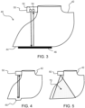
- Figure 3 shows a first example of a collection vessel system 40 for use with a breast pump such as shown in Figures 1 or 2 .
- the collection vessel system 40 comprises a collection vessel 42 for collecting milk expressed during use of the breast pump.
- the collection vessel 42 has a base 44.
- the collection vessel may have a single orientation (e.g. it is placed on a horizontal surface) or it may have a range of possible orientations in the case of a wearable system.
- the base is the lowest surface to which the milk flows in use.
- a sensor system 50 is provided for sensing the start of milk expression into the collection vessel 42.
- the sensor system comprises an emitter 52 for emitting electromagnetic radiation towards the base 44 and a sensor 54 for receiving electromagnetic radiation reflected from the base.
- the sensor system is mounted at a top of the collection vessel 42 facing the base 44 of the collection vessel.
- the base 44 of the collection vessel 42 when empty has a first, relatively low, reflectance to the emitted electromagnetic radiation, in particular below 10%, whereas the collected milk has a second, relatively high, reflectance to the emitted electromagnetic radiation, in particular above 20%.
- the sensor system 50 can thereby detect a change in reflectance to identify when there is a change from an empty collection vessel to a collection vessel containing milk.
- the sensor system can thus detect the first few drops of milk by detecting a change of reflectance from the bottom of the collection vessel.
- the base 44 of the collection vessel may have a dark surface appearance when empty, for example provided by an absorbing layer 46 beneath the base, and the vessel itself is transparent to the radiation used by the sensor system.
- the absorbing layer may be part of the vessel itself (e.g. an external surface coating) or it may be a layer on which the vessel is seated when the breast pump is assembled.
- the absorbing layer 46 for example reflects only a small fraction of the electromagnetic radiation to which it is exposed. When white milk covers a part of the dark bottom of the collection vessel 42, the reflectance increases significantly and that increase can be detected by the sensor system.
- the emitter 52 may be a visible light source or an infrared light source, and correspondingly the sensor 54 may be a visible light sensor or an infrared sensor.
- the sensing may be based on the use of a near infrared LED and suitable detector (which could be a broadband detector with suitable filtering to be selective to the LED frequency).
- the change in reflectance can be obtained simply based on a comparison of the intensity of the emitted radiation and intensity of the received reflected radiation.
- the sensor system In order to detect the first drops of expressed milk, the sensor system should be directed to the lowest point of the base of the vessel 42.
- Figure 4 shows that a well 60 may be provided as the lowest point, so that the first expressed milk drops flow to a known location, for all intended orientations of the vessel in use.
- Figure 5 shows that instead of sensing reflection from a localized point, the emitter and sensor may have a field of view 70 which covers all parts of the base to which the first expressed milk may flow. Milk at any location of the base will result in a reflection. The reflection from the milk surface will be diffuse rather than specular, so a portion of the reflected radiation will be directed back to the sensor, if it has a corresponding field of view.
- the sensor system may comprise a time of flight measurement system, which records a time duration for the emitted radiation to return to the sensor. A distance is thus measured based on the time it takes for the electromagnetic radiation to travel to the reflecting surface and back. This can enable a milk level within the collection vessel to be determined as well as the initial presence of milk.
- the sensor system may record a time taken to make a time of flight measurement and to derive the change in reflectance from the time taken to make time of flight measurement.
- Time of flight (ToF) sensors perform several measurements in rapid succession and then averages out the data. This all happens in a fully automated manner inside the time of flight sensor.
- This time it takes to perform the multiple measurements is for example called the "convergence time” (for example in time of flight sensors of ST microelectronics TM ).
- the convergence time can be looked up in a register of the time of flight sensor.
- the time of flight sensor may record a total execution time, which is the sum of a pre-calibration time (e.g. 3.2ms), a range convergence time (variable) and a readout averaging time (e.g. 4.3ms). There is a maximum overall execution time.
- a pre-calibration time e.g. 3.2ms
- a range convergence time variable
- a readout averaging time e.g. 4.3ms
- a time of flight sensor may be the VL6180 proximity sensing module of ST Microelectronics TM . It uses an IR emitter and range sensor and has the pre-calibration and readout averaging times outlined above.
- the range convergence time is dependent on the reflectance and the range of the target, as shown by table 1 below taken from the production data datasheet of the VL6180.
- the range convergence times are in ms.
- the time taken to obtain a time of flight measurement may in this way be used as a proxy for a reflectance measurement.
- the change in reflectance may be derived from a rate of change of the time taken to make the of flight measurements.
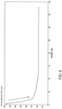
- Figure 6 shows a graph of convergence time versus weight of collected milk.
- the convergence time is initially approximately 0.75ms but it rapidly drops to around 0.3ms during the collection of the initial 10g of milk.
- the steep negative initial slope may be used to detect the initial change in reflectance. This may provide tolerance when there is a small initial amount of residue in the milk vessel.
- the change in convergence time is the result in the change of reflectance.
- reflectance values, convergence times or rate of change of convergence time is used as the measure, a change is detected from the first reflectance (of the empty container vessel base) to a milk reflectance, and thus identify when there is a change from an empty collection vessel to a collection vessel containing milk.
- the reflectance of milk in the IR wavelength range is for example in the range 50% to 70%.
- a minimum reflectance of the milk in the selected wavelength of the sensor system may be 40%, for example 50% for example 60%.
- the reflectance of the container to the IR wavelength can be made to be below 20%, for example below 15% for example below 10%, for example below 5% in the wavelength range of interest.
- the breast pump can be controlled between a stimulation setting and an expression setting.
- the stimulation setting for example involves applying a first, relatively low level of vacuum (by which is meant a pressure only slightly below ambient pressure) at a first relatively high cycle rate (short cycles).
- the expression setting then involves applying a second, relatively high level of vacuum (by which is meant a pressure below ambient pressure by a greater amount) at a second, relatively low cycle rate (long cycles).
- Examples of typical pressure and cycle timings for the stimulation setting are -170mbar (-17kPa, i.e. 17kPa below atmospheric pressure) and a cycle of duration of 0.6 s.
- the pressure is in the range -10kPa to -20kPa with a cycle duration of less than 1.0s.
- Examples of typical pressure and cycle timings for the expression settings are -250mbar (-25kPa, i.e. 25kPa below atmospheric pressure) and a cycle duration of 1.2s.
- the pressure is in the range --22kPa to -35kPa with a cycle duration of more than Is, for example 1.0s to 1.5s.
- the processing of the sensor signals may be performed at various possible locations.
- the processing may built in to the breast pump system, or integrated with the sensor system (for example it may be a clip-on feature) or in a remote device such as a mobile phone, or even hosted remotely in the cloud.
- the example above makes use of a "dark" layer to absorb the radiation used by the sensor system.
- the dark layer may be a black absorbing layer. If IR radiation is used for the sensing, the "dark" layer may be transparent to at least some visible light, and some transparent plastics are IR absorbing.
- the vessel is in particular preferably designed such that for the radiation being used, the reflectance of the at least the base of the vessel when empty is significantly different to the reflectance of milk.
- the absorbing layer may be a coating on the outside of the milk container, or the material of the entire milk container may have the desired absorption characteristics. It will need to meet food standards, particularly if the absorbing layer is in contact with the milk in the container.
- the absorbing material may instead be part of a support on which the milk container is seated, in use. In such a case, the milk container itself may be transparent to the radiation used.
- a single processor or other unit may fulfill the functions of several items recited in the claims.
- a computer program may be stored/distributed on a suitable medium, such as an optical storage medium or a solid-state medium supplied together with or as part of other hardware, but may also be distributed in other forms, such as via the Internet or other wired or wireless telecommunication systems.
- a suitable medium such as an optical storage medium or a solid-state medium supplied together with or as part of other hardware, but may also be distributed in other forms, such as via the Internet or other wired or wireless telecommunication systems.
Abstract
A sensor system is for sensing the start of milk expression into a collection vessel when using a breast pump device. A sensor is used to provide a signal indicating the presence of the first milk expressed, for use in controlling the breast pump to switch from a stimulation mode to an expression mode. The sensor detects a change in the reflectance of the base of the collection vessel to the electromagnetic radiation used by the sensor.
Description
- The invention relates to a breast pump device and a method of operating a breast pump device, and in particular relates to a sensor arrangement for use as part of the breast pump device.
- Breast pumps are used by breast feeding women to extract milk from their breast such that the extracted milk can be fed to their babies at a later time.
- It is well known that best nutrition for babies is breast milk. The world health organization (WHO) recommends to breast feed babies for at least one year, preferably longer. However, mothers often go back to work after only several weeks or months. To provide the best nutrition to their babies, mothers may then express milk using a breast pump. The expressed milk can be stored and given to the baby at a later stage and/or by somebody else.
- To use a breast pump, the breast is typically placed into a funnel-shaped cup and a vacuum is applied such that milk is extracted. A motorized breast pump typically has two operating modes, namely a stimulation mode and an extraction mode. During the stimulation mode, the milk ejection reflex is stimulated. When the breast pump is activated, a pressure source such as a vacuum pump inside the breast pump generates a vacuum and the stimulation mode can be started. The vacuum pump is typically driven by an electric motor. For portable breast pumps, these motors are driven by battery power.
- Wearable breast pumps are characterized in that they can be fully worn on the user's body, allowing the user to move around freely. Some of these are small enough to fit into a user's bra. A motor, battery and milk container are for example integrated to form a single unit.
- However, at the moment, the transition from the stimulation mode to the expression mode is not based on detection of MER, it is either time-based, i.e. a fixed time after switching on, or manual by pushing a button. Both these methods have drawbacks. The timing method is based on an average time, so late for a lot of women and too early for others. The manual method has the drawback that not every woman feels that the milk is flowing and they have to check the bottle. Therefore, detection when milk starts flowing into the bottle would allow for a personalized solution for automatic switching between the stimulation mode and the expression mode.
- It would be desirable to be able to detect the first drop or drops, to enable automatic switching between a stimulation mode and an expression mode.
-
WO 2019/149486 discloses a breast pump which includes a sensor arrangement for detecting a volume of expressed milk. The sensor arrangement is used to measure a free fall time of milk droplets, and thereby determine a liquid level of the milk collection vessel into which the milk droplets are falling. It is also recognized that the start of the milk let-down reflex can be detected based on a sudden increase in volume of collected milk. The pump settings of the breast pump may then be adjusted. - However, this approach requires a volume of milk to be collected before detection is possible of a change in the rate at which the volume increases. Thus, it is not suitable for detecting the first drop or drops of expressed milk.
- There is therefore a need for an improved sensor arrangement for early detection of the initial milk expression.
- The invention is defined by the claims.
- According to examples in accordance with the invention, there is provided a collection vessel system for use with a breast pump, comprising:
- a collection vessel for collecting milk expressed during use of the breast pump, the collection vessel having a base; and
- a sensor system for sensing the start of milk expression into the collection vessel,
- wherein the sensor system comprises an emitter for emitting electromagnetic radiation towards the base and a sensor for receiving electromagnetic radiation reflected from the base,
- wherein:
- the base of the collection vessel when empty has a first reflectance to the emitted electromagnetic radiation below 20%; or
- the collection vessel system comprises a support on which the collection vessel is mounted in use, and the combination of the base (44) of the collection vessel and the support, when the collection vessel is empty, has a first reflectance to the emitted electromagnetic radiation below 20%, and
- wherein the sensor system is for detecting a change from the first reflectance to a milk reflectance, thereby to identify when there is a change from an empty collection vessel to a collection vessel containing milk.
- The invention is thus based on the use of a sensor which can detect the first few drops of milk by detecting a change of reflectance against the bottom of the collection vessel. For example, the base of the collection vessel may have a dark surface appearance when empty (for the example of visible light). More generally, it has a low reflectance (below 10%) to the electromagnetic radiation used by the sensor system. This will be termed "dark" for simplicity. This dark surface reflects only a few percent of the electromagnetic radiation to which it is exposed. When white milk covers the dark bottom of collection vessel, the reflectance increases significantly (to above 20%).
- The emitter is for example for emitting visible light and the sensor is for detecting visible light.
- The emitter may instead be for emitting infrared light and the sensor is for detecting infrared light.
- The change of reflectance can be measured in several ways, for example by measuring the reflectance directly with visible light or with infrared light. A known amount of light is emitted, and the sensor measures the amount of reflected light.
- The sensor system may comprise a time of flight measurement system.
- A time of flight sensor can measure a distance based on the time it takes for the electromagnetic radiation to travel to the reflecting surface and bounce back. This can enable a milk level within the collection vessel to be determined as well as the initial presence of milk.
- The sensor system is for example adapted to record a time taken to make a time of flight measurement and to derive the change in reflectance from the time taken to make a time of flight measurement.
- One option is for the time of flight sensor to measure reflectance directly as well as calculating a time of flight. However, many existing time of flight sensors do not provide access to the raw detection signal. Instead, a time taken to obtain a time of flight measurement may also be used as a proxy for a reflectance measurement. This enables many more off-the-shelf time of flight sensors to be used.
- When the reflectance is low, the time of flight sensor needs to make more measurements before a time of flight measurement is generated, hence it takes longer to determine the distance. Thus, rather than directly measuring a light reflectance, a difference in measurement time can be used to indicate the reflectance of the bottom of the container and hence determine if there is milk present or not.
- In another example, the sensor system is adapted to derive the change in reflectance from a rate of change of the time taken to make time of flight measurements. Thus, rather than relying on the absolute value of the time taken to make a time of flight measurement, a slope of the change in time taken over time may be used.
- The collection vessel for example comprises, or is associated with, an absorbing layer at or beneath the base of the collection vessel. This provides the desired reflectance contrast between an empty collection vessel and one with a small amount of collected milk. If the collection vessel system comprises a support on which the collection vessel is mounted in use, the support for example comprises an absorbing layer.
- The sensor system is for example faces the base of the collection vessel. It may be mounted at the top or at a side of the collection vessel.
- The sensor system may for example sense the reflectance at a particular location which is preferably the lowest location of the base in use, so that it is where milk will first collect. There may for example be a well for this purpose, so that the sensor system is detected the lowest point of the collection vessel for all intended orientations of the collection vessel in use. Instead, the emitter of the sensor system may provide its output to an area of the base so that milk at any location on the base will result in an increased reflection.
- The invention also provides a breast pump device, comprising
at least one breast receiving portion configured to receive a breast of a user; and the collection vessel system as defined above. - The breast pump device may comprise:
- a pressure source coupled to the at least one breast receiving portion; and
- a controller configured to control an operation of the pressure source in a stimulation mode and an expression mode,
- wherein the controller is configured to switch from a stimulation mode to an expression mode in response to a signal from the sensor system of the collection vessel system.
- The invention also provides a method of controlling a breast pump device for the non-therapeutic expression of milk, comprising:
- determining the start of milk expression into a collection vessel system when using the breast pump device based on received data from a sensor system which senses a change in reflectance of a base of the collection vessel system to electromagnetic radiation used by the sensor system from below 20% to a reflectance indicative of a collection vessel containing milk; and
- generating an output based on the determined start of milk expression.
- The method may comprise using the generated output to control the breast pump device to switch from a stimulation mode to an expression mode in response to the determined start of milk expression.
- The invention also provides a computer program comprising computer program code which is adapted, when said program is run on the controller of the breast pump device defined above to implement the method defined above.
- The invention also provides a controller for determining a start of milk collection into a collection vessel, wherein the controller is adapted to:
- receive data from a sensor system, sensing a change in reflectance of a base of the collection vessel to electromagnetic radiation used by the sensor system from below 20% to a reflectance indicative of a collection vessel containing milk; and
- interpret the received data to determine the start of milk collection and generate an output based on the determined start of milk collection.
- The controller may be adapted to interpret the received data by analyzing convergence times of time of flight sensor data.
- These and other aspects of the invention will be apparent from and elucidated with reference to the embodiments described hereinafter.
- For a better understanding of the invention, and to show more clearly how it may be carried into effect, reference will now be made, by way of example only, to the accompanying drawings, in which:
-
Figure 1 shows the typical parts of a known breast pump system; -
Figure 2 shows a wearable breast pump; -
Figure 3 shows a first example of a collection vessel system for use with a breast pump; -
Figure 4 shows a second example of a collection vessel system for use with a breast pump; -
Figure 5 shows a third example of a collection vessel system for use with a breast pump; and -
Figure 6 shows a graph of convergence time versus weight of collected milk. - The invention will be described with reference to the Figures.
- It should be understood that the detailed description and specific examples, while indicating exemplary embodiments of the apparatus, systems and methods, are intended for purposes of illustration only and are not intended to limit the scope of the invention. These and other features, aspects, and advantages of the apparatus, systems and methods of the present invention will become better understood from the following description, appended claims, and accompanying drawings. It should be understood that the Figures are merely schematic and are not drawn to scale. It should also be understood that the same reference numerals are used throughout the Figures to indicate the same or similar parts.
- The invention provides a sensor system for sensing the start of milk expression into a collection vessel when using a breast pump device. A sensor is used to provide a signal indicating the presence of the first milk expressed, for use in controlling the breast pump to switch from a stimulation mode to an expression mode. The sensor detects a change in the reflectance of the base of the collection vessel to the electromagnetic sensing radiation used by the sensor.
-
Figure 1 shows a known breast pump system 1, comprising an expression unit 2 and a drive arrangement for controlling the expression function of the breast pump. - In the example shown, the drive arrangement comprises a
pump arrangement 3 which is connected via a tube 4 to the expression unit 2. The pump arrangement includes various components in addition to a pump impeller and the pump motor, so may be considered to be a general operating unit. - The expression unit 2 is formed with a
main body 7, a funnel 5 (known as a breast shield) for receiving a breast of a user and areceptacle 6 for collecting the expressed milk. Thefunnel 5 and thereceptacle 6 are connected to themain body 7. Themain body 7 comprises a vacuum chamber. A flexible membrane known as the diaphragm is located in the vacuum chamber. The diaphragm prevents expressed milk from flowing into the tube 4 leading to thepump arrangement unit 3. - The operating unit, including the
pump arrangement 3, may instead be directly mounted and connected to themain body 7. In this case, the membrane prevents expressed milk from flowing directly into thepump arrangement 3. - The
pump arrangement 3 comprises acontroller 10, apower source 12, amotor 14 and a vacuum pump 16 (i.e. the impeller driven by the motor 14). The controller controls 10 the operation of thepower source 12,motor 14 andvacuum pump 16. Thepump arrangement 3 further comprises asolenoid valve 18. - In use, the
vacuum pump 16 applies a vacuum to the membrane located in themain body 7 so that it deforms. The membrane deforms to create a vacuum in thefunnel 5 which in turns applies a vacuum to the breast which enables milk to be expressed. - The vacuum is applied to the breast at intervals. That is, a pressure differential is applied on a cyclic basis. After a vacuum has been established, the pressure from the vacuum is released by the use of the solenoid valve which is temporarily opened. The solenoid valve is an electromechanically operated valve configured to open and close an air passage that connects to the vacuum side of the vacuum pump to ambient air such that when the solenoid valve is closed, the vacuum pump generates a vacuum in the expression unit which enables milk to be expressed from the breast of a user. When the solenoid valve is opened, the vacuum generated by the vacuum pump is released as ambient air flows towards the vacuum or negative pressure created by the vacuum pump such that the pressure exerted on the breast of a user is partially or completely reduced.
- This is a basic description of the known operation of a standard breast pump system.
- There are also wearable breast pumps, which are for example for mounting within a feeding bra. All of the drivetrain components described above are then formed within an outer enclosure which fits over the breast. A top part contains the drivetrain (pump, motor, controller) and a bottom part forms the collection vessel. This enables breast pumping to be performed more discretely.
- There are also other types of wearable breast pump whereby the expression unit is fixed to a breast and the pump unit and/or milk container are situated elsewhere on the body of a user.
-
Figure 2 shows a wearable breast pump, comprising anexpression kit 30 attached to a respectivemilk collection vessel 31. - The invention provides a sensor system for sensing the start of milk expression into the milk collection vessel when using a breast pump device. A sensor is used to provide a signal indicating the presence of the first milk expressed, for use in controlling the breast pump to switch from a stimulation mode to an expression mode.
-
Figure 3 shows a first example of acollection vessel system 40 for use with a breast pump such as shown inFigures 1 or 2 . - The
collection vessel system 40 comprises acollection vessel 42 for collecting milk expressed during use of the breast pump. Thecollection vessel 42 has abase 44. In use, the collection vessel may have a single orientation (e.g. it is placed on a horizontal surface) or it may have a range of possible orientations in the case of a wearable system. The base is the lowest surface to which the milk flows in use. - A
sensor system 50 is provided for sensing the start of milk expression into thecollection vessel 42. The sensor system comprises anemitter 52 for emitting electromagnetic radiation towards thebase 44 and asensor 54 for receiving electromagnetic radiation reflected from the base. - The sensor system is mounted at a top of the
collection vessel 42 facing thebase 44 of the collection vessel. - The
base 44 of thecollection vessel 42 when empty has a first, relatively low, reflectance to the emitted electromagnetic radiation, in particular below 10%, whereas the collected milk has a second, relatively high, reflectance to the emitted electromagnetic radiation, in particular above 20%. Thesensor system 50 can thereby detect a change in reflectance to identify when there is a change from an empty collection vessel to a collection vessel containing milk. - The sensor system can thus detect the first few drops of milk by detecting a change of reflectance from the bottom of the collection vessel. For example, the
base 44 of the collection vessel may have a dark surface appearance when empty, for example provided by an absorbinglayer 46 beneath the base, and the vessel itself is transparent to the radiation used by the sensor system. - The absorbing layer may be part of the vessel itself (e.g. an external surface coating) or it may be a layer on which the vessel is seated when the breast pump is assembled. The absorbing
layer 46 for example reflects only a small fraction of the electromagnetic radiation to which it is exposed. When white milk covers a part of the dark bottom of thecollection vessel 42, the reflectance increases significantly and that increase can be detected by the sensor system. - It has been found that only a thin film of milk is needed to enable detection to take place, for example around 2ml for a typical wearable breast pump container.
- The
emitter 52 may be a visible light source or an infrared light source, and correspondingly thesensor 54 may be a visible light sensor or an infrared sensor. For example, the sensing may be based on the use of a near infrared LED and suitable detector (which could be a broadband detector with suitable filtering to be selective to the LED frequency). - The change in reflectance can be obtained simply based on a comparison of the intensity of the emitted radiation and intensity of the received reflected radiation.
- In order to detect the first drops of expressed milk, the sensor system should be directed to the lowest point of the base of the
vessel 42. -
Figure 4 shows that a well 60 may be provided as the lowest point, so that the first expressed milk drops flow to a known location, for all intended orientations of the vessel in use. -
Figure 5 shows that instead of sensing reflection from a localized point, the emitter and sensor may have a field ofview 70 which covers all parts of the base to which the first expressed milk may flow. Milk at any location of the base will result in a reflection. The reflection from the milk surface will be diffuse rather than specular, so a portion of the reflected radiation will be directed back to the sensor, if it has a corresponding field of view. - The sensor system may comprise a time of flight measurement system, which records a time duration for the emitted radiation to return to the sensor. A distance is thus measured based on the time it takes for the electromagnetic radiation to travel to the reflecting surface and back. This can enable a milk level within the collection vessel to be determined as well as the initial presence of milk.
- The sensor system may record a time taken to make a time of flight measurement and to derive the change in reflectance from the time taken to make time of flight measurement.
- Known time of flight (ToF) sensors perform several measurements in rapid succession and then averages out the data. This all happens in a fully automated manner inside the time of flight sensor.
- This time it takes to perform the multiple measurements is for example called the "convergence time" (for example in time of flight sensors of ST microelectronics ™). The convergence time can be looked up in a register of the time of flight sensor.
- For example, the time of flight sensor may record a total execution time, which is the sum of a pre-calibration time (e.g. 3.2ms), a range convergence time (variable) and a readout averaging time (e.g. 4.3ms). There is a maximum overall execution time.
- It is of interest to use the convergence time because the raw receiver data is not externally accessible in many off-the-shelf time of flight sensors.
- By way of example, a time of flight sensor may be the VL6180 proximity sensing module of ST Microelectronics ™. It uses an IR emitter and range sensor and has the pre-calibration and readout averaging times outlined above.
- It returns the actual range convergence time (not including the readout averaging time). The range convergence time is dependent on the reflectance and the range of the target, as shown by table 1 below taken from the production data datasheet of the VL6180. The range convergence times are in ms.
Table 1 Range (mm) Target reflectance 3% 5% 17% 88% 10 0.43 0.33 0.18 0.18 20 0.94 0.73 0.28 0.18 30 1.89 1.40 0.51 0.18 40 3.07 2.25 0.81 0.18 50 4.35 3.24 1.18 0.24 60 5.70 4.22 1.60 0.32 70 7.07 5.35 2.07 0.49 80 8.41 6.45 2.58 0.50 90 9.58 7.56 3.14 0.61 100 10.73 8.65 3.69 0.73 - It can be seen that for a typical 100mm range (the height of the milk container), there is a factor of around 10 between the range convergence time for a 5% reflectance compared to a 88% reflectance.
- This is because when the reflectance is low, the time of flight sensor needs to make more measurements before a time of flight measurement is generated, hence it takes longer to determine the distance. Thus, rather than directly measuring a light reflectance, a difference in measurement time can be used to indicate the reflectance of the bottom of the container and hence determine if there is milk present or not.
- The time taken to obtain a time of flight measurement may in this way be used as a proxy for a reflectance measurement.
- Instead of, or as well as, using the time taken to obtain a time of flight measurement, the change in reflectance may be derived from a rate of change of the time taken to make the of flight measurements.
-
Figure 6 shows a graph of convergence time versus weight of collected milk. - As shown, the convergence time is initially approximately 0.75ms but it rapidly drops to around 0.3ms during the collection of the initial 10g of milk. Thus, rather than using absolute values of the convergence time, the steep negative initial slope may be used to detect the initial change in reflectance. This may provide tolerance when there is a small initial amount of residue in the milk vessel.
- The change in convergence time is the result in the change of reflectance. Thus, whether reflectance values, convergence times or rate of change of convergence time is used as the measure, a change is detected from the first reflectance (of the empty container vessel base) to a milk reflectance, and thus identify when there is a change from an empty collection vessel to a collection vessel containing milk.
- By way of example, the reflectance of milk in the IR wavelength range is for example in the
range 50% to 70%. Thus a minimum reflectance of the milk in the selected wavelength of the sensor system may be 40%, for example 50% for example 60%. - The reflectance of the container to the IR wavelength can be made to be below 20%, for example below 15% for example below 10%, for example below 5% in the wavelength range of interest.
- As mentioned above, by sensing the first expressed milk, the breast pump can be controlled between a stimulation setting and an expression setting.
- The stimulation setting for example involves applying a first, relatively low level of vacuum (by which is meant a pressure only slightly below ambient pressure) at a first relatively high cycle rate (short cycles).
- The expression setting then involves applying a second, relatively high level of vacuum (by which is meant a pressure below ambient pressure by a greater amount) at a second, relatively low cycle rate (long cycles).
- Examples of typical pressure and cycle timings for the stimulation setting are -170mbar (-17kPa, i.e. 17kPa below atmospheric pressure) and a cycle of duration of 0.6 s. Typically, the pressure is in the range -10kPa to -20kPa with a cycle duration of less than 1.0s.
- Examples of typical pressure and cycle timings for the expression settings are -250mbar (-25kPa, i.e. 25kPa below atmospheric pressure) and a cycle duration of 1.2s. Typically, the pressure is in the range --22kPa to -35kPa with a cycle duration of more than Is, for example 1.0s to 1.5s.
- These are just examples to give an indication of the typical difference between the expression mode and the stimulation mode.
- The processing of the sensor signals may be performed at various possible locations. The processing may built in to the breast pump system, or integrated with the sensor system (for example it may be a clip-on feature) or in a remote device such as a mobile phone, or even hosted remotely in the cloud.
- The example above makes use of a "dark" layer to absorb the radiation used by the sensor system.
- In the case of visible or infrared light, the dark layer may be a black absorbing layer. If IR radiation is used for the sensing, the "dark" layer may be transparent to at least some visible light, and some transparent plastics are IR absorbing.
- However, other parts of the electromagnetic spectrum may be used. The vessel is in particular preferably designed such that for the radiation being used, the reflectance of the at least the base of the vessel when empty is significantly different to the reflectance of milk.
- The absorbing layer may be a coating on the outside of the milk container, or the material of the entire milk container may have the desired absorption characteristics. It will need to meet food standards, particularly if the absorbing layer is in contact with the milk in the container. The absorbing material may instead be part of a support on which the milk container is seated, in use. In such a case, the milk container itself may be transparent to the radiation used.
- Variations to the disclosed embodiments can be understood and effected by those skilled in the art in practicing the claimed invention, from a study of the drawings, the disclosure and the appended claims. In the claims, the word "comprising" does not exclude other elements or steps, and the indefinite article "a" or "an" does not exclude a plurality.
- A single processor or other unit may fulfill the functions of several items recited in the claims.
- The mere fact that certain measures are recited in mutually different dependent claims does not indicate that a combination of these measures cannot be used to advantage.
- A computer program may be stored/distributed on a suitable medium, such as an optical storage medium or a solid-state medium supplied together with or as part of other hardware, but may also be distributed in other forms, such as via the Internet or other wired or wireless telecommunication systems.
- If the term "adapted to" is used in the claims or description, it is noted the term "adapted to" is intended to be equivalent to the term "configured to".
- Any reference signs in the claims should not be construed as limiting the scope.
Claims (15)
- A collection vessel system (40) for use with a breast pump, comprising:a collection vessel (42) for collecting milk expressed during use of the breast pump, the collection vessel having a base (44); anda sensor system (50) for sensing the start of milk expression into the collection vessel,wherein the sensor system comprises an emitter (52) for emitting electromagnetic radiation towards the base (44) and a sensor (54) for receiving electromagnetic radiation reflected from the base,wherein:the base (44) of the collection vessel when empty has a first reflectance to the emitted electromagnetic radiation below 20%; orthe collection vessel system comprises a support on which the collection vessel is mounted in use, and the combination of the base (44) of the collection vessel and the support, when the collection vessel is empty, has a first reflectance to the emitted electromagnetic radiation below 20%, andwherein the sensor system is for detecting a change from the first reflectance to a milk reflectance, thereby to identify when there is a change from an empty collection vessel to a collection vessel containing milk.
- The collection vessel system of claim 1, wherein the emitter (52) is for emitting visible light and the sensor (54) is for detecting visible light.
- The collection vessel system of claim 1, wherein the emitter (52) is for emitting infrared light and the sensor (54) is for detecting infrared light.
- The collection vessel system of claim 1, wherein the sensor system comprises a time of flight measurement system.
- The collection vessel system of claim 4, wherein the sensor system is adapted to record a time taken thereby to make a time of flight measurement and to derive the change in reflectance from the time taken to make the time of flight measurement.
- The collection vessel system of claim 5, wherein the sensor system is adapted to derive the change in reflectance from a rate of change of the time taken to make the of flight measurements.
- The collection vessel system of any one of claims 1 to 6, wherein the collection vessel system comprises the support on which the collection vessel is mounted in use, and the support comprises an absorbing layer (46).
- A breast pump device, comprising
at least one breast receiving portion (5) configured to receive a breast of a user; and the collection vessel system of any one of claims 1 to 7. - The breast pump device of claim 8, comprising:a pressure source (16) coupled to the at least one breast receiving portion; anda controller (10) configured to control an operation of the pressure source in a stimulation mode and an expression mode,wherein the controller is configured to switch from a stimulation mode to an expression mode in response to a signal from the sensor system of the collection vessel system.
- The breast pump device of claim 8 or 9, comprising a wearable breast pump.
- A method of controlling a breast pump device for the non-therapeutic expression of milk, comprising:determining the start of milk expression into a collection vessel system when using the breast pump device based on received data from a sensor system which senses a change in reflectance of a base of a collection vessel of the collection vessel system to electromagnetic radiation used by the sensor system from below 20% to a reflectance indicative of a collection vessel containing milk; andgenerating an output based on the determined start of milk expression.
- The method of claim 11, comprising using the generated output to control the breast pump device to switch from a stimulation mode to an expression mode in response to the determined start of milk expression.
- A computer program comprising computer program code which is adapted, when said program is run on the controller of the breast pump device of claim 9 to implement the method of claim 11 or 12.
- A controller for determining a start of milk collection into a collection vessel, wherein the controller is adapted to:receive data from a sensor system, sensing a change in reflectance of a base of the collection vessel to electromagnetic radiation used by the sensor system from below 20% to a reflectance indicative of a collection vessel containing milk; andinterpret the received data to determine the start of milk collection and generate an output based on the determined start of milk collection.
- The controller of claim 14, adapted to interpret the received data by analyzing convergence times of time of flight sensor data.
Priority Applications (4)
| Application Number | Priority Date | Filing Date | Title |
|---|---|---|---|
| EP21208923.9A EP4183430A1 (en) | 2021-11-18 | 2021-11-18 | Sensor arrangement for a breast pump device and breast pump device using the sensor arrangement |
| PCT/EP2022/081375 WO2023088758A1 (en) | 2021-11-18 | 2022-11-10 | Sensor arrangement for a breast pump device and breast pump device using the sensor arrangement |
| CN202223055772.4U CN219847590U (en) | 2021-11-18 | 2022-11-17 | Collecting container system, breast pump device and controller |
| CN202211441683.5A CN116135239A (en) | 2021-11-18 | 2022-11-17 | Sensor device for breast pump device and breast pump device using sensor device |
Applications Claiming Priority (1)
| Application Number | Priority Date | Filing Date | Title |
|---|---|---|---|
| EP21208923.9A EP4183430A1 (en) | 2021-11-18 | 2021-11-18 | Sensor arrangement for a breast pump device and breast pump device using the sensor arrangement |
Publications (1)
| Publication Number | Publication Date |
|---|---|
| EP4183430A1 true EP4183430A1 (en) | 2023-05-24 |
Family
ID=78695543
Family Applications (1)
| Application Number | Title | Priority Date | Filing Date |
|---|---|---|---|
| EP21208923.9A Withdrawn EP4183430A1 (en) | 2021-11-18 | 2021-11-18 | Sensor arrangement for a breast pump device and breast pump device using the sensor arrangement |
Country Status (3)
| Country | Link |
|---|---|
| EP (1) | EP4183430A1 (en) |
| CN (2) | CN116135239A (en) |
| WO (1) | WO2023088758A1 (en) |
Citations (4)
| Publication number | Priority date | Publication date | Assignee | Title |
|---|---|---|---|---|
| WO2019149486A1 (en) | 2018-02-02 | 2019-08-08 | Koninklijke Philips N.V. | Breast pump device comprising an expression kit, a vacuum unit and a milk expression assessment system |
| US20190328945A1 (en) * | 2018-04-27 | 2019-10-31 | Moxxly, Inc. | Liquid level sensor for liquid receptacle |
| US20200016306A1 (en) * | 2016-09-22 | 2020-01-16 | Medela Holding Ag | Breastshield unit |
| US20210268158A1 (en) * | 2017-06-15 | 2021-09-02 | Chiaro Technology Limited | Breast pump system |
Family Cites Families (1)
| Publication number | Priority date | Publication date | Assignee | Title |
|---|---|---|---|---|
| SG184227A1 (en) | 2010-03-25 | 2012-10-30 | Aop Orphan Pharmaceuticals Ag | Novel composition for treatment of essential thrombocythemia |
-
2021
- 2021-11-18 EP EP21208923.9A patent/EP4183430A1/en not_active Withdrawn
-
2022
- 2022-11-10 WO PCT/EP2022/081375 patent/WO2023088758A1/en unknown
- 2022-11-17 CN CN202211441683.5A patent/CN116135239A/en active Pending
- 2022-11-17 CN CN202223055772.4U patent/CN219847590U/en active Active
Patent Citations (4)
| Publication number | Priority date | Publication date | Assignee | Title |
|---|---|---|---|---|
| US20200016306A1 (en) * | 2016-09-22 | 2020-01-16 | Medela Holding Ag | Breastshield unit |
| US20210268158A1 (en) * | 2017-06-15 | 2021-09-02 | Chiaro Technology Limited | Breast pump system |
| WO2019149486A1 (en) | 2018-02-02 | 2019-08-08 | Koninklijke Philips N.V. | Breast pump device comprising an expression kit, a vacuum unit and a milk expression assessment system |
| US20190328945A1 (en) * | 2018-04-27 | 2019-10-31 | Moxxly, Inc. | Liquid level sensor for liquid receptacle |
Also Published As
| Publication number | Publication date |
|---|---|
| CN219847590U (en) | 2023-10-20 |
| CN116135239A (en) | 2023-05-19 |
| WO2023088758A1 (en) | 2023-05-25 |
Similar Documents
| Publication | Publication Date | Title |
|---|---|---|
| CN106724604A (en) | A kind of multifunctional intellectual cup and its health management system arranged | |
| JP2005516687A (en) | Milking cup | |
| EP3746145B1 (en) | Breast pump device comprising an expression kit, a vacuum unit and a milk expression assessment system | |
| AU2017329208B2 (en) | Breastshield unit | |
| EP4183430A1 (en) | Sensor arrangement for a breast pump device and breast pump device using the sensor arrangement | |
| WO2019137013A1 (en) | Smart microwave oven and smart device having food identification function | |
| CN111787962B (en) | Breast pump device | |
| CN205612344U (en) | Food processor | |
| CN209346686U (en) | Water dispenser | |
| US20200061263A1 (en) | Breast pump device comprising a volatile component analysis system | |
| US20150305635A1 (en) | Portable electronic device and heart rate sensing method of the same | |
| CN111220238A (en) | Automatic detection device and detection method for liquid level of oil cup | |
| US20230285646A1 (en) | Sensor arrangement for a breast pump device and breast pump device using the sensor arrangement | |
| CN211066224U (en) | Pot capable of detecting temperature and capacity in pot | |
| EP3970764A1 (en) | Breast pump device and controller for the device, and a control method | |
| EP3474916A2 (en) | Body drainage apparatus | |
| RU2773304C2 (en) | Appliance with a breast pump | |
| CN216256731U (en) | Cooking device with optical detection function | |
| CN114521798B (en) | Cooking appliance, operation control method thereof, controller and readable storage medium | |
| CN211048976U (en) | Multifunctional mirror | |
| EP3960217A1 (en) | Breast pump device and controller for the device, and a control method | |
| CN114533011A (en) | Heart rate detection assembly and terminal | |
| CN117731869A (en) | Milk sucking amount detection method, intelligent breast pump control method and breast pump | |
| CN115175394A (en) | Heating device with weight sensing function and heating method | |
| CN113842057A (en) | Cooking detection device and method and cooking equipment |
Legal Events
| Date | Code | Title | Description |
|---|---|---|---|
| PUAI | Public reference made under article 153(3) epc to a published international application that has entered the european phase |
Free format text: ORIGINAL CODE: 0009012 |
|
| STAA | Information on the status of an ep patent application or granted ep patent |
Free format text: STATUS: THE APPLICATION HAS BEEN PUBLISHED |
|
| AK | Designated contracting states |
Kind code of ref document: A1 Designated state(s): AL AT BE BG CH CY CZ DE DK EE ES FI FR GB GR HR HU IE IS IT LI LT LU LV MC MK MT NL NO PL PT RO RS SE SI SK SM TR |
|
| STAA | Information on the status of an ep patent application or granted ep patent |
Free format text: STATUS: THE APPLICATION IS DEEMED TO BE WITHDRAWN |
|
| 18D | Application deemed to be withdrawn |
Effective date: 20231125 |