EP4183358A1 - Jaw tip support for tapered jaw member - Google Patents
Jaw tip support for tapered jaw member Download PDFInfo
- Publication number
- EP4183358A1 EP4183358A1 EP22207989.9A EP22207989A EP4183358A1 EP 4183358 A1 EP4183358 A1 EP 4183358A1 EP 22207989 A EP22207989 A EP 22207989A EP 4183358 A1 EP4183358 A1 EP 4183358A1
- Authority
- EP
- European Patent Office
- Prior art keywords
- jaw member
- insulative spacer
- insulative
- tissue
- structural frame
- Prior art date
- Legal status (The legal status is an assumption and is not a legal conclusion. Google has not performed a legal analysis and makes no representation as to the accuracy of the status listed.)
- Pending
Links
Images


Classifications
-
- A—HUMAN NECESSITIES
- A61—MEDICAL OR VETERINARY SCIENCE; HYGIENE
- A61B—DIAGNOSIS; SURGERY; IDENTIFICATION
- A61B18/00—Surgical instruments, devices or methods for transferring non-mechanical forms of energy to or from the body
- A61B18/04—Surgical instruments, devices or methods for transferring non-mechanical forms of energy to or from the body by heating
- A61B18/12—Surgical instruments, devices or methods for transferring non-mechanical forms of energy to or from the body by heating by passing a current through the tissue to be heated, e.g. high-frequency current
- A61B18/14—Probes or electrodes therefor
- A61B18/1442—Probes having pivoting end effectors, e.g. forceps
- A61B18/1445—Probes having pivoting end effectors, e.g. forceps at the distal end of a shaft, e.g. forceps or scissors at the end of a rigid rod
-
- A—HUMAN NECESSITIES
- A61—MEDICAL OR VETERINARY SCIENCE; HYGIENE
- A61B—DIAGNOSIS; SURGERY; IDENTIFICATION
- A61B18/00—Surgical instruments, devices or methods for transferring non-mechanical forms of energy to or from the body
- A61B2018/00053—Mechanical features of the instrument of device
- A61B2018/00059—Material properties
- A61B2018/00071—Electrical conductivity
- A61B2018/00083—Electrical conductivity low, i.e. electrically insulating
-
- A—HUMAN NECESSITIES
- A61—MEDICAL OR VETERINARY SCIENCE; HYGIENE
- A61B—DIAGNOSIS; SURGERY; IDENTIFICATION
- A61B18/00—Surgical instruments, devices or methods for transferring non-mechanical forms of energy to or from the body
- A61B2018/00053—Mechanical features of the instrument of device
- A61B2018/00059—Material properties
- A61B2018/00089—Thermal conductivity
- A61B2018/00101—Thermal conductivity low, i.e. thermally insulating
-
- A—HUMAN NECESSITIES
- A61—MEDICAL OR VETERINARY SCIENCE; HYGIENE
- A61B—DIAGNOSIS; SURGERY; IDENTIFICATION
- A61B18/00—Surgical instruments, devices or methods for transferring non-mechanical forms of energy to or from the body
- A61B2018/00571—Surgical instruments, devices or methods for transferring non-mechanical forms of energy to or from the body for achieving a particular surgical effect
- A61B2018/00601—Cutting
-
- A—HUMAN NECESSITIES
- A61—MEDICAL OR VETERINARY SCIENCE; HYGIENE
- A61B—DIAGNOSIS; SURGERY; IDENTIFICATION
- A61B18/00—Surgical instruments, devices or methods for transferring non-mechanical forms of energy to or from the body
- A61B18/04—Surgical instruments, devices or methods for transferring non-mechanical forms of energy to or from the body by heating
- A61B18/12—Surgical instruments, devices or methods for transferring non-mechanical forms of energy to or from the body by heating by passing a current through the tissue to be heated, e.g. high-frequency current
- A61B18/14—Probes or electrodes therefor
- A61B18/1442—Probes having pivoting end effectors, e.g. forceps
- A61B2018/1452—Probes having pivoting end effectors, e.g. forceps including means for cutting
- A61B2018/1455—Probes having pivoting end effectors, e.g. forceps including means for cutting having a moving blade for cutting tissue grasped by the jaws
Definitions
- the present disclosure relates to surgical instruments and, more specifically, to end effector assemblies for surgical instruments, such as for use in robotic surgical systems.
- Robotic surgical systems are increasingly utilized in various different surgical procedures.
- Some robotic surgical systems include a console supporting a robotic arm.
- One or more different surgical instruments may be configured for use with the robotic surgical system and selectively mountable to the robotic arm.
- the robotic arm provides one or more inputs to the mounted surgical instrument to enable operation of the mounted surgical instrument.
- a surgical forceps one type of instrument capable of being utilized with a robotic surgical system, relies on mechanical action between its jaw members to grasp, clamp, and constrict tissue. Electrosurgical forceps utilize both mechanical clamping action and energy to heat tissue to treat, e.g., coagulate, cauterize, or seal, tissue. Typically, once tissue is treated, the tissue is severed using a cutting element. Certain electrosurgical forceps utilize a tapered jaw design to facilitate dissection and access to smaller operating cavities. Manufacturing a jaw member with a consistent strength and stiffness profiles to absorb the necessary closure pressures associated with tissue sealing can present design challenges especially at the tapered distal tip.
- distal refers to the portion that is being described which is further from an operator (whether a human surgeon or a surgical robot), while the term “proximal” refers to the portion that is being described which is closer to the operator.
- proximal refers to the portion that is being described which is closer to the operator.
- the terms "about,” substantially,” and the like, as utilized herein, are meant to account for manufacturing, material, environmental, use, and/or measurement tolerances and variations, and in any event may encompass differences of up to 10%. Further, to the extent consistent, any of the aspects described herein may be used in conjunction with any or all of the other aspects described herein.
- a jaw member of an electrosurgical instrument which includes a U-shaped structural frame defining a cavity therein and extending therealong configured to receive at least a portion of an insulative spacer therein such that the insulative spacer extends distally therefrom.
- the insulative spacer includes a tapered fin at a distal end thereof.
- a tissue treating plate is disposed on the face of the insulative spacer, the tissue treating plate is adapted to connect to a source of energy to treat tissue therewith.
- the tapered fin is configured to extend to and support a distal end of the tissue treating plate.
- the insulative spacer is configured to electrically isolate the structural frame from the tissue treating plate.
- the tapered fin includes an overhang on either side thereof configured to laterally support the distal end of the tissue treating plate.
- the jaw member includes an outer insulative jacket disposed about at least a portion of an outer face of the structural frame and the insulative spacer.
- the outer insulative jacket is overmolded about the structural frame and the insulative spacer.
- the insulative spacer is made from a material selected from the group consisting of: PPA, PTFE, PEEK, PBI and PEI.
- the draft angle of the tapered fin is about 0.5 degrees.
- the draft angle may be in the range of about 3 degrees to about 10 degrees.
- the insulative spacer is configured to receive a thermal cutting element therein and extending therealong. In other aspects of the present disclosure, the insulative spacer is configured to electrically isolate the structural frame from the thermal cutting element.
- an end effector of an electrosurgical instrument which includes first and second jaw members pivotably coupled to one another such that at least one of the first or second jaw members is movable relative to the other from a spaced-apart position to an approximated position to grasp tissue therebetween.
- Each of the first and/or second jaw members includes: a U-shaped structural frame defining a cavity therein and extending therealong configured to receive at least a portion of an insulative spacer therein such that the insulative spacer extends distally therefrom, the insulative spacer includes a tapered fin at a distal end thereof; and a tissue treating plate disposed on the face of the insulative spacer, the tissue treating plates of each jaw member disposed in vertical opposition relative to one another and each tissue treating plate is adapted to connect to an opposite potential from a source of energy to treat tissue therewith, each tapered fin is configured to extend to and support a distal end of the respective tissue treating plate.
- each insulative spacer is configured to electrically isolate the structural frame from the tissue treating plate of each respective jaw member.
- each tapered fin includes an overhang on either side thereof configured to laterally support the distal end of the tissue treating plate of each respective jaw member.
- each jaw member includes an outer insulative jacket disposed about at least a portion of an outer face of the structural frame and the insulative spacer of each respective jaw member.
- the outer insulative jacket is overmolded about the structural frame and the insulative spacer of each respective jaw member.
- the insulative spacer of each jaw member is made from a material selected from the group consisting of: PPA, PTFE, PEEK, PBI and PEI.
- the draft angle of each tapered fin is about 0.5 degrees.
- the draft angle may be in the range of about 3 degrees to about 10 degrees.
- the insulative spacer of the first jaw member is configured to receive a thermal cutting element therein and extending therealong. In other aspects of the present disclosure, the insulative spacer of the first jaw member is configured to electrically isolate the structural frame from the thermal cutting element.
- a surgical instrument 10 provided in accordance with the present disclosure generally includes a housing 20, a shaft 30 extending distally from the housing 20, an end effector assembly 100 extending distally from the shaft 30, and an actuation assembly 300 disposed within the housing 20 and operably associated with the shaft 30 and the end effector assembly 100.
- the surgical instrument 10 is detailed herein as an articulating electrosurgical forceps configured for use with a robotic surgical system, e.g., robotic surgical system 500 ( FIG. 3 ).
- robotic surgical system 500 FIG. 3
- the aspects and features of the surgical instrument 10 provided in accordance with the present disclosure, detailed below, are equally applicable for use with other suitable surgical instruments (including non-robotic surgical instrument) and/or in other suitable surgical systems (including non-robotic surgical systems).
- the housing 20 of the surgical instrument 10 includes first and second body portions 22a, 22b and a proximal faceplate 24 ( FIG. 2 ) that cooperate to enclose the actuation assembly 300 therein.
- the proximal faceplate 24 includes apertures defined therein through which inputs 410, 420, 430, 440 of the actuation assembly 300 extend.
- a pair of latch levers extends outwardly from opposing sides of the housing 20 and enables releasable engagement (directly or indirectly) of the housing 20 with a robotic arm of a surgical system, e.g., robotic surgical system 500 ( FIG. 3 ).
- An aperture 28 defined through the housing 20 permits a thumbwheel 640 to extend therethrough to enable manual manipulation of the thumbwheel 640 from the exterior of the housing 20 to permit manual opening and closing of the end effector assembly 100.
- the shaft 30 of the surgical instrument 10 includes a distal segment 32 (such as, for example, a collar or clevis), a proximal segment 34, and an articulating section 36 disposed between the distal and proximal segments 32, 34, respectively.
- the articulating section 36 includes one or more articulating components 37, e.g., links, joints, etc.
- a plurality of articulation cables 38 e.g., four (4) articulation cables, or other suitable actuators, extends through the articulating section 36.
- the articulation cables 38 are operably coupled to the distal segment 32 of the shaft 30 at the distal ends thereof and extend proximally from the distal segment 32 of the shaft 30, through the articulating section 36 and the proximal segment 34 of the shaft 30, and into the housing 20, wherein the articulation cables 38 operably couple with an articulation assembly 200 of the actuation assembly 300 to enable selective articulation of the distal segment 32 (and, thus the end effector assembly 100) relative to the proximal segment 34 and the housing 20, e.g., about at least two axes of articulation (yaw and pitch articulation, for example).
- the articulation assembly 200 is operably coupled between the first and second inputs 410, 420, respectively, of the actuation assembly 300 and the articulation cables 38 ( FIG. 1 ) such that, upon receipt of appropriate rotational inputs into the first and/or second inputs 410, 420, the articulation assembly 200 manipulates the articulation cables 38 to articulate the end effector assembly 100 in a desired direction, e.g., to pitch and/or yaw the end effector assembly 100.
- the articulation cables 38 are arranged in a generally rectangular configuration, although other suitable configurations are also contemplated.
- actuation of the articulation cables 38 is effected in pairs. More specifically, in order to pitch the end effector assembly 100, the upper pair of cables 38 is actuated in a similar manner while the lower pair of cables 38 is actuated in a similar manner relative to one another but an opposite manner relative to the upper pair of cables 38. With respect to yaw articulation, the right pair of cables 38 is actuated in a similar manner while the left pair of cables 38 is actuated in a similar manner relative to one another but an opposite manner relative to the right pair of cables 38.
- a robotic surgical system 500 is configured for use in accordance with the present disclosure. Aspects and features of the robotic surgical system 500 not germane to the understanding of the present disclosure are omitted to avoid obscuring the aspects and features of the present disclosure in unnecessary detail.
- the robotic surgical system 500 generally includes a plurality of robot arms 502, 503; a control device 504; and an operating console 505 coupled with control device 504.
- the operating console 505 may include a display device 506, which may be set up in particular to display three-dimensional images; and manual input devices 507, 508, by means of which a person, e.g., a surgeon, may be able to telemanipulate the robot arms 502, 503 in a first operating mode.
- the robotic surgical system 500 may be configured for use on a patient 513 lying on a patient table 512 to be treated in a minimally invasive manner.
- the robotic surgical system 500 may further include a database 514, in particular coupled to the control device 504, in which are stored, for example, pre-operative data from the patient 513 and/or anatomical atlases.
- Each of the robot arms 502, 503 may include a plurality of members, which are connected through joints, and a mounted device which may be, for example, a surgical tool "ST.”
- a surgical tool "ST” may be the surgical instrument 10 ( FIG. 1 ), thus providing such functionality on a robotic surgical system 500.
- the actuation assembly 300 ( FIG. 2 ) is configured to operably interface with the robotic surgical system 500 when the surgical instrument 10 is mounted on the robotic surgical system 500 to enable robotic operation of the actuation assembly 300. That is, the robotic surgical system 500 selectively provides rotational inputs to inputs 410, 420, 430, 440 of the actuation assembly 300 to articulate the end effector assembly 100, grasp tissue between the first and second jaw members 110, 120, and/or cut tissue grasped between the first and second jaw members 110, 120.
- the robot arms 502, 503 may be driven by electric drives, e.g., motors, connected to the control device 504.
- the control device 504 e.g., a computer, may be configured to activate the motors, in particular by means of a computer program, in such a way that the robot arms 502, 503, and, thus, their mounted surgical tools "ST" execute a desired movement and/or function according to a corresponding input from the manual input devices 507, 508, respectively.
- the control device 504 may also be configured in such a way that it regulates the movement of the robot arms 502, 503 and/or of the motors.
- end effector assembly 100 includes first and second jaw members 110, 120.
- Either or both jaw members 110, 120 may include a structural frame 111, 121, an insulative spacer 112, 122, a tissue treating plate 113, 123 defining the respective tissue treating surface 114, 124 thereof, and, in aspects, an outer insulative jacket 116, 126.
- Tissue treating plates 113, 123 may be pre-formed and engaged with insulative spacers 112, 122 and/or other portion(s) of jaw members 110, 120 via, for example, overmolding, adhesion, mechanical engagement, etc., or may be deposited onto insulative spacers 112, 122, e.g., via sputtering or other suitable deposition technique.
- jaw member 120 includes a generally U-shaped structural frame 121, an insulative spacer 122, a tissue treating plate 123 defining a tissue treating surface 124, and, in aspects, an outer insulative jacket 126 ( FIG. 4 ).
- Structural frame 121 may be formed from stainless steel or other suitable material configured to provide structural support to jaw member 120.
- Structural frame is typically stamped in a U-shaped configuration and defines a cavity 121a defined therealong configured to at least partially receive the insulative space 122.
- the frame may be forged, cast or otherwise fabricated.
- Structural frame 121 includes a proximal flange portion 152 about which jaw member 120 is pivotably coupled to jaw member 110 via pivot 103 ( FIG. 4 ) and a distal body portion 154 that supports the other components of jaw member 120, e.g., insulative spacer 122, tissue treating plate 123, and outer insulative jacket 126 (where provided).
- proximal flange portion 152 enables operable coupling of jaw member 120 to the actuation assembly 200 to enable pivoting of jaw member 110 relative to jaw member 120 in response to actuation thereof.
- Many suitable drive arrangements are contemplated, e.g., using cam pins and cam slots, a screw-drive mechanism, etc.
- Insulative spacer 122 of jaw member 120 is formed from an electrically insulative material capable of withstanding high temperatures, e.g., above at least 300°C, although other configurations are also contemplated. Insulative spacer 122 may be formed from ceramic or other suitable material, e.g., PPA, PTFE, PEEK, PBI and PEI. Insulative spacer 122 may include various cutout or apertures defined therealong to facilitate assembly of jaw member 120.
- insulative spacer 122 is configured for at least partial receipt within distal body portion 154 of structural frame 121 and may be at least partially shaped complementary thereto. Insulative spacer 122 may include one or more alignment features to facilitate assembly to frame 121, e.g., alignment bosses, flanges, etc.
- Overhang 176 of insulative spacer 122 is configured to be supported on longitudinally extending sides of the distal body portion 154 of structural frame 121 ( FIG. 6 ). Overhang 176 may also be configured to provide electrical insulation between the seal plate and other structural components.
- tissue treating plate 123 is supported or received on insulative spacer 122.
- tissue treating plate 123 overlaps the overhangs 176 of insulative spacer 122, although other configurations are also contemplated.
- tissue treating plate 123 may be pre-formed and engaged with insulative spacer 122 or may be deposited onto insulative spacers 122, e.g., via sputtering or other suitable deposition technique.
- tissue treating plate 123 may be secured to jaw member 120 and, thus, insulative spacer 122, via overmolding of outer insulative jacket 126 about distal body portion 154 of structural frame 121 of tissue treating plate 123.
- Tissue treating plate 123 may include a longitudinally extending slot 128 defined therethrough and along at least a portion of the length thereof.
- Slot 128 may be transversely centered on tissue treating surface 124 or may be offset relative thereto and may be linear, curved, include angled sections, etc. similarly or differently from the configuration, e.g., curvature, of jaw member 120. Slot 128 exposes a portion of insulative spacer 122 and may be recessed relative to tissue treating surface 124, substantially co-planar with tissue treating surface 124, or protruding beyond tissue treating surface 124 towards jaw member 110. In other aspects, slot 128 is omitted and, thus tissue treating plate 123 extends continuously insulative spacer 122 without exposing any portion thereof.
- tissue treating plate 123 Regardless of the particular configuration of tissue treating plate 123, insulative spacer 122 electrically isolates tissue treating plate 123 from structural frame 121.
- Tissue treating plate 123 is electrically connected, e.g., via one or more electrical leads (not shown), to an activation switch (not shown)) and an electrosurgical generator “G" ( FIG. 1 ) to enable selective energization of tissue treating plate 123, e.g., as one pole of a bipolar Radio Frequency (RF) electrosurgical circuit.
- RF Radio Frequency
- Jaw member 120 further includes a thermal cutting element 130 which may be connected to the same (e.g., generator "G") or alternate electrical energy source.
- a mechanical cutting element (not shown) may also be employed which is configured to translate a cutting blade through the tissue upon selective application thereof.
- a second activation switch may be integrated with the robotic system 500 and coupled to the thermal cutting element 130 and to the electrosurgical generator "G" for enabling the selective activation of the supply of energy to the thermal cutting element 130 for thermally cutting tissue.
- Thermal cutting element 130 may be secured within and directly to insulative spacer 122 in any suitable manner, e.g., adhesive, friction fitting, mechanical engagement, etc., or may be indirectly secured within insulative spacer 122 via attachment to one or more other components of jaw member 120. Thermal cutting element 130 may protrude distally beyond the distal tip of insulative spacer 122 of jaw member 120, may be substantially flush therewith, or may be recessed relative thereto. In aspects where end effector assembly 100, or a portion thereof, is curved, thermal cutting element 130 may similarly be curved. Thermal cutting element 130 is electrically connected, e.g., via one or more electrical leads (not shown), to electrosurgical generator "G" ( FIG.
- Thermal cutting element 130 may be configured to cut previously (or concurrently) sealed tissue grasped between jaw members 110, 120, to cut tissue extending across jaw member 120, and/or to cut tissue adjacent the distal end of jaw member 120.
- Thermal cutting element 130 may be any suitable thermal cutting element such as, for example, a resistive cutting element, a ferromagnetic cutting element, a monopolar cutting element, a bipolar cutting element, etc.
- thermal cutting element 130 may include a substrate, e.g., aluminum, ceramic, stainless steel, etc., an insulative coating disposed on the substrate, e.g., a Plasma Electrolytic Oxidation (PEO)-formed coating, a sprayed coating, a deposited coating, or other suitable coating, and a heating circuit trace disposed on the coating such that when an AC voltage is applied to the heating circuit trace, the thermal cutting element 130 is heated for thermally cutting tissue in contact therewith or adjacent thereto.
- PEO Plasma Electrolytic Oxidation
- jaw member 110 includes a structural frame 111, an insulative spacer 112, a tissue treating plate 113 defining tissue treating surface 114, and, in aspects, an outer insulative jacket 116. Jaw member 110 is similar to jaw member 120 with the general exception of thermal cutting element 130 being housed therein.
- Structural frame 121 of jaw member 120 defines a proximal flange portion 152 and a distal body portion 154 extending distally from proximal flange portion 152.
- Proximal flange portion 152 may be bifurcated to define a pair of spaced apart proximal flange portion segments or may define any other suitable configuration.
- Proximal flange portion 152 of jaw member 120 and proximal flange portion 188 of jaw member 110 may define a nestled configuration, e.g., wherein one of the proximal flange portions 152, 188 is received within the other, an overlapping configuration, e.g., wherein proximal flange portions 152, 188 at least partially overlap one another, or an offset configuration, e.g., wherein proximal flange portions 152, 188 are positioned in side-by-side relation.
- proximal flanges are configured for receipt of pivot 103, e.g., welded or otherwise secured therein, to pivotably couple jaw members 110, 120 with one another.
- Insulative spacer 112 of jaw member 110 may be configured similarly as and may include any of the features of insulative spacer 122 of jaw member 120 and, thus, only differences therebetween are described below.
- tissue treating plate 113 defines tissue treating surface 114 and is supported on insulative spacer 112 similarly as tissue treating plate 123 is supported on insulative spacer 122.
- Tissue treating plate 113 may be formed similarly to and/or include any of the features of tissue treating plate 123 and may be secured to jaw member 110 similarly as tissue treating plate 123 is secured to jaw member 120, e.g., via overmolding of outer insulative jacket 116.
- Insulative spacer 112 electrically isolates tissue treating plate 113 from structural frame 111.
- spacer 122 includes a reduced profile at a distal end thereof that is shaped like a fin 122a that extends under and supports the corresponding distal end 123a of the tissue treating plate 123.
- spacer 122 includes a reduced profile at a distal end thereof that is shaped like a fin 122a that extends under and supports the corresponding distal end 123a of the tissue treating plate 123.
- the stamped (or otherwise fabricated) U-shaped configuration of the structure frame, e.g., frame 121, is reduced in length proximate the distal end of the jaw member 120 for manufacturing purposes.
- the structural frame e.g., frame 121, does not support the distal end 123a of the tissue treating plate 123.
- the distal ends 113a, 123a of the of the jaw members 110, 120, respectively, are supported by the corresponding fins 112a ( FIG. 4 ), 122a associated with each of the same.
- This support geometry also allows the tissue treating plates 113, 123 to "fully seat" near the jaw tip, thus reducing the opportunity for flash to leak around and over the distal end of the tissue treating plates 113, 123 during molding.
- Fins 112a, 122a are made from the same materials as the spacers 112, 122 mentioned above, namely, ceramic or other suitable material, e.g., PPA, Polytetrafluoroethylene (PTFE), polyetheretherketone (PEEK), Polyetherimide (PEI), polybenzimidazole (PBI) etc. Fins 112a, 122a are integrally associated, e.g., overmolded in single unitary construction, with spacers 112 and 122 or may be affixed in some other fashion, e.g., adhesive. As such, the fins 112a, 122a are typically overmolded at the same time as the spacers 112, 122 over the respective structural frames 111, 121.
- PPA Polytetrafluoroethylene
- PEEK polyetheretherketone
- PEI Polyetherimide
- PBI polybenzimidazole
- Jaw member 110 typically includes a fin 112a dimensioned having a height "H” of about 0.040 inches, a length “L” of about 0.040 inches, a width “W” of about 0.012 inches and a draft angle alpha " ⁇ " of about 0.5 degrees.
- Jaw member 120 typically includes a fin 122a dimensioned having a height "H” of about 0.050 inches, a length “L” of about 0.040 inches, a width "W” of about 0.012 inches and a draft angle alpha " ⁇ " of about 0.5 degrees.
- the lengths and drafts angles of the jaw members 110, 120 may change depending on the overall size of the jaw members for the particular sealing purpose, e.g., sealing vessels or sealing lungs, the desired length of the tapered distal ends 113a, 123a of the jaw members 110, 120, etc.
- draft angles in the range of 0° to about 10° are contemplated.
Abstract
A jaw member of an electrosurgical instrument includes a U-shaped structural frame defining a cavity therein and extending therealong configured to receive at least a portion of an insulative spacer therein such that the insulative spacer extends distally therefrom. The insulative spacer includes a tapered fin at a distal end thereof. A tissue treating plate is disposed on the face of the insulative spacer, the tissue treating plate is adapted to connect to a source of energy to treat tissue therewith. The tapered fin is configured to extend to and support a distal end of the tissue treating plate.
Description
- This application claims the benefit of
U.S. Provisional Application Serial No. 63/281,185 filed November 19, 2021 - The present disclosure relates to surgical instruments and, more specifically, to end effector assemblies for surgical instruments, such as for use in robotic surgical systems.
- Robotic surgical systems are increasingly utilized in various different surgical procedures. Some robotic surgical systems include a console supporting a robotic arm. One or more different surgical instruments may be configured for use with the robotic surgical system and selectively mountable to the robotic arm. The robotic arm provides one or more inputs to the mounted surgical instrument to enable operation of the mounted surgical instrument.
- A surgical forceps, one type of instrument capable of being utilized with a robotic surgical system, relies on mechanical action between its jaw members to grasp, clamp, and constrict tissue. Electrosurgical forceps utilize both mechanical clamping action and energy to heat tissue to treat, e.g., coagulate, cauterize, or seal, tissue. Typically, once tissue is treated, the tissue is severed using a cutting element. Certain electrosurgical forceps utilize a tapered jaw design to facilitate dissection and access to smaller operating cavities. Manufacturing a jaw member with a consistent strength and stiffness profiles to absorb the necessary closure pressures associated with tissue sealing can present design challenges especially at the tapered distal tip.
- As used herein, the term "distal" refers to the portion that is being described which is further from an operator (whether a human surgeon or a surgical robot), while the term "proximal" refers to the portion that is being described which is closer to the operator. The terms "about," substantially," and the like, as utilized herein, are meant to account for manufacturing, material, environmental, use, and/or measurement tolerances and variations, and in any event may encompass differences of up to 10%. Further, to the extent consistent, any of the aspects described herein may be used in conjunction with any or all of the other aspects described herein.
- Provided in accordance with aspects of the present disclosure is a jaw member of an electrosurgical instrument which includes a U-shaped structural frame defining a cavity therein and extending therealong configured to receive at least a portion of an insulative spacer therein such that the insulative spacer extends distally therefrom. The insulative spacer includes a tapered fin at a distal end thereof. A tissue treating plate is disposed on the face of the insulative spacer, the tissue treating plate is adapted to connect to a source of energy to treat tissue therewith. The tapered fin is configured to extend to and support a distal end of the tissue treating plate.
- In an aspect of the present disclosure, the insulative spacer is configured to electrically isolate the structural frame from the tissue treating plate.
- In an aspect of the present disclosure, the tapered fin includes an overhang on either side thereof configured to laterally support the distal end of the tissue treating plate.
- In an aspect of the present disclosure, the jaw member includes an outer insulative jacket disposed about at least a portion of an outer face of the structural frame and the insulative spacer. In other aspects of the present disclosure, the outer insulative jacket is overmolded about the structural frame and the insulative spacer.
- In an aspect of the present disclosure, the insulative spacer is made from a material selected from the group consisting of: PPA, PTFE, PEEK, PBI and PEI.
- In an aspect of the present disclosure, the draft angle of the tapered fin is about 0.5 degrees. The draft angle may be in the range of about 3 degrees to about 10 degrees.
- In an aspect of the present disclosure, the insulative spacer is configured to receive a thermal cutting element therein and extending therealong. In other aspects of the present disclosure, the insulative spacer is configured to electrically isolate the structural frame from the thermal cutting element.
- Provided in accordance with aspects of the present disclosure is an end effector of an electrosurgical instrument which includes first and second jaw members pivotably coupled to one another such that at least one of the first or second jaw members is movable relative to the other from a spaced-apart position to an approximated position to grasp tissue therebetween. Each of the first and/or second jaw members includes: a U-shaped structural frame defining a cavity therein and extending therealong configured to receive at least a portion of an insulative spacer therein such that the insulative spacer extends distally therefrom, the insulative spacer includes a tapered fin at a distal end thereof; and a tissue treating plate disposed on the face of the insulative spacer, the tissue treating plates of each jaw member disposed in vertical opposition relative to one another and each tissue treating plate is adapted to connect to an opposite potential from a source of energy to treat tissue therewith, each tapered fin is configured to extend to and support a distal end of the respective tissue treating plate.
- In an aspect of the present disclosure, each insulative spacer is configured to electrically isolate the structural frame from the tissue treating plate of each respective jaw member.
- In an aspect of the present disclosure, each tapered fin includes an overhang on either side thereof configured to laterally support the distal end of the tissue treating plate of each respective jaw member.
- In an aspect of the present disclosure, each jaw member includes an outer insulative jacket disposed about at least a portion of an outer face of the structural frame and the insulative spacer of each respective jaw member. In other aspects of the present disclosure, the outer insulative jacket is overmolded about the structural frame and the insulative spacer of each respective jaw member.
- In an aspect of the present disclosure, the insulative spacer of each jaw member is made from a material selected from the group consisting of: PPA, PTFE, PEEK, PBI and PEI.
- In an aspect of the present disclosure, the draft angle of each tapered fin is about 0.5 degrees. The draft angle may be in the range of about 3 degrees to about 10 degrees.
- In an aspect of the present disclosure, the insulative spacer of the first jaw member is configured to receive a thermal cutting element therein and extending therealong. In other aspects of the present disclosure, the insulative spacer of the first jaw member is configured to electrically isolate the structural frame from the thermal cutting element.
- Various aspects and features of the present disclosure are described hereinbelow with reference to the drawings wherein:
-
FIG. 1 is a perspective view of a surgical instrument in accordance with the present disclosure configured for mounting on a robotic arm of a robotic surgical system; -
FIG. 2 is a rear perspective view of a proximal portion of the surgical instrument ofFIG. 1 with an outer housing removed; -
FIG. 3 is a schematic illustration of an exemplary robotic surgical system configured to releasably receive the surgical instrument ofFIG. 1 . -
FIG. 4 is a side view of an end effector assembly of the forceps ofFIG. 1 including first and second jaw members; -
FIG. 5 is a perspective view of a first jaw member of the end effector assembly with outer insulative jackets removed therefrom to expose an insulative spacer; -
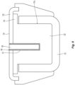
FIG. 6 is a transverse, cross-sectional view of the first jaw member of the end effector assembly as shown inFIG. 4 ; and -
FIG. 7 is an enlarged view of the distal tapered fin of the insulative spacer of the jaw member ofFIG. 5 . - Referring to
FIGS. 1 and2 , asurgical instrument 10 provided in accordance with the present disclosure generally includes ahousing 20, ashaft 30 extending distally from thehousing 20, anend effector assembly 100 extending distally from theshaft 30, and anactuation assembly 300 disposed within thehousing 20 and operably associated with theshaft 30 and theend effector assembly 100. Thesurgical instrument 10 is detailed herein as an articulating electrosurgical forceps configured for use with a robotic surgical system, e.g., robotic surgical system 500 (FIG. 3 ). However, the aspects and features of thesurgical instrument 10 provided in accordance with the present disclosure, detailed below, are equally applicable for use with other suitable surgical instruments (including non-robotic surgical instrument) and/or in other suitable surgical systems (including non-robotic surgical systems). - The
housing 20 of thesurgical instrument 10 includes first andsecond body portions FIG. 2 ) that cooperate to enclose theactuation assembly 300 therein. Theproximal faceplate 24 includes apertures defined therein through whichinputs actuation assembly 300 extend. A pair of latch levers extends outwardly from opposing sides of thehousing 20 and enables releasable engagement (directly or indirectly) of thehousing 20 with a robotic arm of a surgical system, e.g., robotic surgical system 500 (FIG. 3 ). Anaperture 28 defined through thehousing 20 permits athumbwheel 640 to extend therethrough to enable manual manipulation of thethumbwheel 640 from the exterior of thehousing 20 to permit manual opening and closing of theend effector assembly 100. - The
shaft 30 of thesurgical instrument 10 includes a distal segment 32 (such as, for example, a collar or clevis), aproximal segment 34, and an articulating section 36 disposed between the distal andproximal segments articulating components 37, e.g., links, joints, etc. A plurality ofarticulation cables 38, e.g., four (4) articulation cables, or other suitable actuators, extends through the articulating section 36. More specifically, thearticulation cables 38 are operably coupled to thedistal segment 32 of theshaft 30 at the distal ends thereof and extend proximally from thedistal segment 32 of theshaft 30, through the articulating section 36 and theproximal segment 34 of theshaft 30, and into thehousing 20, wherein thearticulation cables 38 operably couple with anarticulation assembly 200 of theactuation assembly 300 to enable selective articulation of the distal segment 32 (and, thus the end effector assembly 100) relative to theproximal segment 34 and thehousing 20, e.g., about at least two axes of articulation (yaw and pitch articulation, for example). Thearticulation assembly 200 is operably coupled between the first andsecond inputs actuation assembly 300 and the articulation cables 38 (FIG. 1 ) such that, upon receipt of appropriate rotational inputs into the first and/orsecond inputs articulation assembly 200 manipulates thearticulation cables 38 to articulate theend effector assembly 100 in a desired direction, e.g., to pitch and/or yaw theend effector assembly 100. Thearticulation cables 38 are arranged in a generally rectangular configuration, although other suitable configurations are also contemplated. - With respect to articulation of the
end effector assembly 100 relative to theproximal segment 34 of theshaft 30, actuation of thearticulation cables 38 is effected in pairs. More specifically, in order to pitch theend effector assembly 100, the upper pair ofcables 38 is actuated in a similar manner while the lower pair ofcables 38 is actuated in a similar manner relative to one another but an opposite manner relative to the upper pair ofcables 38. With respect to yaw articulation, the right pair ofcables 38 is actuated in a similar manner while the left pair ofcables 38 is actuated in a similar manner relative to one another but an opposite manner relative to the right pair ofcables 38. - Turning now to
FIG. 3 , a roboticsurgical system 500 is configured for use in accordance with the present disclosure. Aspects and features of the roboticsurgical system 500 not germane to the understanding of the present disclosure are omitted to avoid obscuring the aspects and features of the present disclosure in unnecessary detail. - The robotic
surgical system 500 generally includes a plurality ofrobot arms control device 504; and anoperating console 505 coupled withcontrol device 504. The operatingconsole 505 may include adisplay device 506, which may be set up in particular to display three-dimensional images; andmanual input devices robot arms surgical system 500 may be configured for use on apatient 513 lying on a patient table 512 to be treated in a minimally invasive manner. The roboticsurgical system 500 may further include adatabase 514, in particular coupled to thecontrol device 504, in which are stored, for example, pre-operative data from thepatient 513 and/or anatomical atlases. - Each of the
robot arms FIG. 1 ), thus providing such functionality on a roboticsurgical system 500. - Specifically, the actuation assembly 300 (
FIG. 2 ) is configured to operably interface with the roboticsurgical system 500 when thesurgical instrument 10 is mounted on the roboticsurgical system 500 to enable robotic operation of theactuation assembly 300. That is, the roboticsurgical system 500 selectively provides rotational inputs toinputs actuation assembly 300 to articulate theend effector assembly 100, grasp tissue between the first andsecond jaw members second jaw members - The
robot arms control device 504. Thecontrol device 504, e.g., a computer, may be configured to activate the motors, in particular by means of a computer program, in such a way that therobot arms manual input devices control device 504 may also be configured in such a way that it regulates the movement of therobot arms - Turning to
FIGS. 4-7 ,end effector assembly 100, as noted above, includes first andsecond jaw members jaw members structural frame insulative spacer tissue treating plate tissue treating surface outer insulative jacket Tissue treating plates insulative spacers jaw members insulative spacers - Referring in particular to
FIG. 5 ,jaw member 120, as noted above, includes a generally U-shapedstructural frame 121, aninsulative spacer 122, atissue treating plate 123 defining atissue treating surface 124, and, in aspects, an outer insulative jacket 126 (FIG. 4 ).Structural frame 121 may be formed from stainless steel or other suitable material configured to provide structural support tojaw member 120. Structural frame is typically stamped in a U-shaped configuration and defines acavity 121a defined therealong configured to at least partially receive theinsulative space 122. The frame may be forged, cast or otherwise fabricated.Structural frame 121 includes aproximal flange portion 152 about whichjaw member 120 is pivotably coupled tojaw member 110 via pivot 103 (FIG. 4 ) and adistal body portion 154 that supports the other components ofjaw member 120, e.g.,insulative spacer 122,tissue treating plate 123, and outer insulative jacket 126 (where provided). In shaft-based or robotic configurations,proximal flange portion 152 enables operable coupling ofjaw member 120 to theactuation assembly 200 to enable pivoting ofjaw member 110 relative tojaw member 120 in response to actuation thereof. Many suitable drive arrangements are contemplated, e.g., using cam pins and cam slots, a screw-drive mechanism, etc. -
Insulative spacer 122 ofjaw member 120 is formed from an electrically insulative material capable of withstanding high temperatures, e.g., above at least 300°C, although other configurations are also contemplated.Insulative spacer 122 may be formed from ceramic or other suitable material, e.g., PPA, PTFE, PEEK, PBI and PEI.Insulative spacer 122 may include various cutout or apertures defined therealong to facilitate assembly ofjaw member 120. - Continuing with reference to
FIG. 5 ,insulative spacer 122 is configured for at least partial receipt withindistal body portion 154 ofstructural frame 121 and may be at least partially shaped complementary thereto.Insulative spacer 122 may include one or more alignment features to facilitate assembly to frame 121, e.g., alignment bosses, flanges, etc.Overhang 176 ofinsulative spacer 122 is configured to be supported on longitudinally extending sides of thedistal body portion 154 of structural frame 121 (FIG. 6 ).Overhang 176 may also be configured to provide electrical insulation between the seal plate and other structural components. - Referring again to
FIGS. 4-7 , as noted above,tissue treating plate 123 is supported or received oninsulative spacer 122. In aspects,tissue treating plate 123 overlaps theoverhangs 176 ofinsulative spacer 122, although other configurations are also contemplated. As noted above,tissue treating plate 123 may be pre-formed and engaged withinsulative spacer 122 or may be deposited ontoinsulative spacers 122, e.g., via sputtering or other suitable deposition technique. In aspects wheretissue treating plate 123 is pre-formed and engaged withinsulative spacer 122,tissue treating plate 123 may be secured tojaw member 120 and, thus,insulative spacer 122, via overmolding of outerinsulative jacket 126 aboutdistal body portion 154 ofstructural frame 121 oftissue treating plate 123.Tissue treating plate 123 may include alongitudinally extending slot 128 defined therethrough and along at least a portion of the length thereof. -
Slot 128 may be transversely centered ontissue treating surface 124 or may be offset relative thereto and may be linear, curved, include angled sections, etc. similarly or differently from the configuration, e.g., curvature, ofjaw member 120.Slot 128 exposes a portion ofinsulative spacer 122 and may be recessed relative totissue treating surface 124, substantially co-planar withtissue treating surface 124, or protruding beyondtissue treating surface 124 towardsjaw member 110. In other aspects,slot 128 is omitted and, thustissue treating plate 123 extends continuouslyinsulative spacer 122 without exposing any portion thereof. - Regardless of the particular configuration of
tissue treating plate 123,insulative spacer 122 electrically isolatestissue treating plate 123 fromstructural frame 121.Tissue treating plate 123 is electrically connected, e.g., via one or more electrical leads (not shown), to an activation switch (not shown)) and an electrosurgical generator "G" (FIG. 1 ) to enable selective energization oftissue treating plate 123, e.g., as one pole of a bipolar Radio Frequency (RF) electrosurgical circuit. However, other suitable energy modalities, e.g., thermal, ultrasonic, light, microwave, infrared, etc., are also contemplated.Jaw member 120 further includes athermal cutting element 130 which may be connected to the same (e.g., generator "G") or alternate electrical energy source. A mechanical cutting element (not shown) may also be employed which is configured to translate a cutting blade through the tissue upon selective application thereof. - A second activation switch (not shown) may be integrated with the
robotic system 500 and coupled to thethermal cutting element 130 and to the electrosurgical generator "G" for enabling the selective activation of the supply of energy to thethermal cutting element 130 for thermally cutting tissue. -
Thermal cutting element 130 may be secured within and directly toinsulative spacer 122 in any suitable manner, e.g., adhesive, friction fitting, mechanical engagement, etc., or may be indirectly secured withininsulative spacer 122 via attachment to one or more other components ofjaw member 120.Thermal cutting element 130 may protrude distally beyond the distal tip ofinsulative spacer 122 ofjaw member 120, may be substantially flush therewith, or may be recessed relative thereto. In aspects whereend effector assembly 100, or a portion thereof, is curved,thermal cutting element 130 may similarly be curved.Thermal cutting element 130 is electrically connected, e.g., via one or more electrical leads (not shown), to electrosurgical generator "G" (FIG. 1 ) to enable selective activation of the supply of energy tothermal cutting element 130 for heatingthermal cutting element 130 to thermally cut tissue.Thermal cutting element 130, more specifically, may be configured to cut previously (or concurrently) sealed tissue grasped betweenjaw members jaw member 120, and/or to cut tissue adjacent the distal end ofjaw member 120. -
Thermal cutting element 130 may be any suitable thermal cutting element such as, for example, a resistive cutting element, a ferromagnetic cutting element, a monopolar cutting element, a bipolar cutting element, etc. With respect to resistive cutting elements,thermal cutting element 130 may include a substrate, e.g., aluminum, ceramic, stainless steel, etc., an insulative coating disposed on the substrate, e.g., a Plasma Electrolytic Oxidation (PEO)-formed coating, a sprayed coating, a deposited coating, or other suitable coating, and a heating circuit trace disposed on the coating such that when an AC voltage is applied to the heating circuit trace, thethermal cutting element 130 is heated for thermally cutting tissue in contact therewith or adjacent thereto. - With reference to
FIG. 4 ,jaw member 110 includes astructural frame 111, aninsulative spacer 112, atissue treating plate 113 definingtissue treating surface 114, and, in aspects, anouter insulative jacket 116.Jaw member 110 is similar tojaw member 120 with the general exception ofthermal cutting element 130 being housed therein. -
Structural frame 121 ofjaw member 120 defines aproximal flange portion 152 and adistal body portion 154 extending distally fromproximal flange portion 152.Proximal flange portion 152 may be bifurcated to define a pair of spaced apart proximal flange portion segments or may define any other suitable configuration.Proximal flange portion 152 ofjaw member 120 andproximal flange portion 188 ofjaw member 110 may define a nestled configuration, e.g., wherein one of theproximal flange portions proximal flange portions proximal flange portions proximal flange portions pivot 103, e.g., welded or otherwise secured therein, to pivotablycouple jaw members -
Insulative spacer 112 ofjaw member 110 may be configured similarly as and may include any of the features ofinsulative spacer 122 ofjaw member 120 and, thus, only differences therebetween are described below. For example,tissue treating plate 113 definestissue treating surface 114 and is supported oninsulative spacer 112 similarly astissue treating plate 123 is supported oninsulative spacer 122.Tissue treating plate 113 may be formed similarly to and/or include any of the features oftissue treating plate 123 and may be secured tojaw member 110 similarly astissue treating plate 123 is secured tojaw member 120, e.g., via overmolding of outerinsulative jacket 116.Insulative spacer 112 electrically isolatestissue treating plate 113 fromstructural frame 111. - Details relating to the
spacer 122 are described in more detail below with reference toFIGS. 4-7 . More particularly,spacer 122 includes a reduced profile at a distal end thereof that is shaped like afin 122a that extends under and supports the correspondingdistal end 123a of thetissue treating plate 123. In order to reduce the configuration of thejaw members 110, 120 (onlyjaw member 120 is shown in detail but the configuration of thespacer 112 is substantially the same) to a tapered profile at a distal end thereof, the stamped (or otherwise fabricated), U-shaped configuration of the structure frame, e.g.,frame 121, is reduced in length proximate the distal end of thejaw member 120 for manufacturing purposes. In other words, the thinner the profile of theframe 121 the more difficult it is to form the U-shape at a distal end. As a result, the structural frame, e.g.,frame 121, does not support thedistal end 123a of thetissue treating plate 123. - To avoid inconsistencies in pressure between the
jaw members distal ends jaw members fins 112a (FIG. 4 ), 122a associated with each of the same. Overhangs 175 (FIG. 4 ) and 176 (FIG. 6 ), which extend laterally fromrespective fins distal tips tissue treating plates tissue treating plates tissue treating plates -
Fins spacers Fins spacers fins spacers structural frames -
Jaw member 110 typically includes afin 112a dimensioned having a height "H" of about 0.040 inches, a length "L" of about 0.040 inches, a width "W" of about 0.012 inches and a draft angle alpha "α" of about 0.5 degrees.Jaw member 120 typically includes afin 122a dimensioned having a height "H" of about 0.050 inches, a length "L" of about 0.040 inches, a width "W" of about 0.012 inches and a draft angle alpha "α" of about 0.5 degrees. The lengths and drafts angles of thejaw members distal ends jaw members - While several aspects of the disclosure have been shown in the drawings, it is not intended that the disclosure be limited thereto, as it is intended that the disclosure be as broad in scope as the art will allow and that the specification be read likewise. For example, the disclosure may incorporate a moving blade (not shown) instead of a
thermal cutting element 130. Obviously various components of thejaw members - It will be understood that various modifications may be made to the aspects and features disclosed herein. Therefore, the above description should not be construed as limiting, but merely as exemplifications of various aspects and features. Those skilled in the art will envision other modifications within the scope and spirit of the claims appended hereto.
- The invention may be described by reference to the following numbered paragraphs:-
- 1. A jaw member of an electrosurgical instrument, comprising:
- a U-shaped structural frame defining a cavity therein and extending therealong configured to receive at least a portion of an insulative spacer therein such that the insulative spacer extends distally therefrom, the insulative spacer including a tapered fin at a distal end thereof; and
- a tissue treating plate disposed on the face of the insulative spacer, the tissue treating plate adapted to connect to a source of energy to treat tissue therewith, the tapered fin configured to extend to and support a distal end of the tissue treating plate.
- 2. The jaw member according to paragraph 1, wherein the insulative spacer is configured to electrically isolate the structural frame from the tissue treating plate.
- 3. The jaw member according to paragraph 1, wherein the tapered fin includes an overhang on either side thereof configured to laterally support the distal end of the tissue treating plate.
- 4. The jaw member according to paragraph 1, further comprising an outer insulative jacket disposed about at least a portion of an outer face of the structural frame and the insulative spacer.
- 5. The jaw member according to
paragraph 4, wherein the outer insulative jacket is overmolded about the structural frame and the insulative spacer. - 6. The jaw member according to paragraph 1, wherein the insulative spacer is made from a material selected from the group consisting of: PPA, PTFE, PEEK, PBI and PEI.
- 7. The jaw member according to paragraph 1, wherein a draft angle of the tapered fin is in the range of zero degrees to about 10 degrees.
- 8. The jaw member according to paragraph 1, wherein the insulative spacer is configured to receive a thermal cutting element therein and extending therealong.
- 9. The jaw member according to paragraph 8, wherein the insulative spacer is configured to electrically isolate the structural frame from the thermal cutting element.
- 10. An end effector of an electrosurgical instrument, comprising:
first and second jaw members pivotably coupled to one another such that at least one of the first or second jaw members is movable relative to the other from a spaced-apart position to an approximated position to grasp tissue therebetween, each of the first or second jaw members including:- a U-shaped structural frame defining a cavity therein and extending therealong configured to receive at least a portion of an insulative spacer therein such that the insulative spacer extends distally therefrom, the insulative spacer including a tapered fin at a distal end thereof; and
- a tissue treating plate disposed on the face of the insulative spacer, the tissue treating plates of each jaw member disposed in vertical opposition relative to one another and each tissue treating plate adapted to connect to an opposite potential from a source of energy to treat tissue therewith, each tapered fin configured to extend to and support a distal end of the respective tissue treating plate.
- 11. The end effector of an electrosurgical instrument according to
paragraph 10, wherein each insulative spacer is configured to electrically isolate the structural frame from the tissue treating plate of each respective jaw member. - 12. The end effector of an electrosurgical instrument according to
paragraph 10, wherein each tapered fin includes an overhang on either side thereof configured to laterally support the distal end of the tissue treating plate of each respective jaw member. - 13. The end effector of an electrosurgical instrument according to
paragraph 10, further comprising an outer insulative jacket disposed about at least a portion of an outer face of the structural frame and the insulative spacer of each respective jaw member. - 14. The end effector of an electrosurgical instrument according to paragraph 13, wherein the outer insulative jacket is overmolded about the structural frame and the insulative spacer of each respective jaw member.
- 15. The end effector of an electrosurgical instrument according to
paragraph 10, wherein the insulative spacer of each jaw member is made from a material selected from the group consisting of: PPA, PTFE, PEEK, PBI and PEI. - 16. The end effector of an electrosurgical instrument according to
paragraph 10, wherein a draft angle of each tapered fin is in the range of zero degrees to about 10 degrees. - 17. The end effector of an electrosurgical instrument according to
paragraph 10, wherein the insulative spacer of the first jaw member is configured to receive a thermal cutting element therein and extending therealong. - 18. The end effector of an electrosurgical instrument according to paragraph 17, wherein the insulative spacer of the first jaw member is configured to electrically isolate the structural frame from the thermal cutting element.
Claims (15)
- A jaw member of an electrosurgical instrument, comprising:a U-shaped structural frame defining a cavity therein and extending therealong configured to receive at least a portion of an insulative spacer therein such that the insulative spacer extends distally therefrom, the insulative spacer including a tapered fin at a distal end thereof; anda tissue treating plate disposed on the face of the insulative spacer, the tissue treating plate adapted to connect to a source of energy to treat tissue therewith, the tapered fin configured to extend to and support a distal end of the tissue treating plate.
- The jaw member according to claim 1, wherein the insulative spacer is configured to electrically isolate the structural frame from the tissue treating plate.
- The jaw member according to claim 1 or claim 2, wherein the tapered fin includes an overhang on either side thereof configured to laterally support the distal end of the tissue treating plate.
- The jaw member according to any preceding claim, further comprising an outer insulative jacket disposed about at least a portion of an outer face of the structural frame and the insulative spacer; preferably wherein the outer insulative jacket is overmolded about the structural frame and the insulative spacer.
- The jaw member according to any preceding claim, wherein the insulative spacer is made from a material selected from the group consisting of: PPA, PTFE, PEEK, PBI and PEI.
- The jaw member according to any preceding claim, wherein a draft angle of the tapered fin is in the range of zero degrees to about 10 degrees.
- The jaw member according to any preceding claim, wherein the insulative spacer is configured to receive a thermal cutting element therein and extending therealong; preferably wherein the insulative spacer is configured to electrically isolate the structural frame from the thermal cutting element.
- An end effector of an electrosurgical instrument, comprising:
first and second jaw members pivotably coupled to one another such that at least one of the first or second jaw members is movable relative to the other from a spaced-apart position to an approximated position to grasp tissue therebetween, each of the first or second jaw members including:a U-shaped structural frame defining a cavity therein and extending therealong configured to receive at least a portion of an insulative spacer therein such that the insulative spacer extends distally therefrom, the insulative spacer including a tapered fin at a distal end thereof; anda tissue treating plate disposed on the face of the insulative spacer, the tissue treating plates of each jaw member disposed in vertical opposition relative to one another and each tissue treating plate adapted to connect to an opposite potential from a source of energy to treat tissue therewith, each tapered fin configured to extend to and support a distal end of the respective tissue treating plate. - The end effector of an electrosurgical instrument according to claim 8, wherein each insulative spacer is configured to electrically isolate the structural frame from the tissue treating plate of each respective jaw member.
- The end effector of an electrosurgical instrument according to claim 8 or claim 9, wherein each tapered fin includes an overhang on either side thereof configured to laterally support the distal end of the tissue treating plate of each respective jaw member.
- The end effector of an electrosurgical instrument according to any of claims 8 to 10, further comprising an outer insulative jacket disposed about at least a portion of an outer face of the structural frame and the insulative spacer of each respective jaw member.
- The end effector of an electrosurgical instrument according to any of claims 8 to 11, wherein the outer insulative jacket is overmolded about the structural frame and the insulative spacer of each respective jaw member.
- The end effector of an electrosurgical instrument according to any of claims 8 to 12, wherein the insulative spacer of each jaw member is made from a material selected from the group consisting of: PPA, PTFE, PEEK, PBI and PEI.
- The end effector of an electrosurgical instrument according to any of claims 8 to 13, wherein a draft angle of each tapered fin is in the range of zero degrees to about 10 degrees.
- The end effector of an electrosurgical instrument according to any of claims 8 to 14, wherein the insulative spacer of the first jaw member is configured to receive a thermal cutting element therein and extending therealong; preferably wherein the insulative spacer of the first jaw member is configured to electrically isolate the structural frame from the thermal cutting element.
Applications Claiming Priority (2)
| Application Number | Priority Date | Filing Date | Title |
|---|---|---|---|
| US202163281185P | 2021-11-19 | 2021-11-19 | |
| US17/958,692 US20230157745A1 (en) | 2021-11-19 | 2022-10-03 | Jaw tip support for tapered jaw member |
Publications (1)
| Publication Number | Publication Date |
|---|---|
| EP4183358A1 true EP4183358A1 (en) | 2023-05-24 |
Family
ID=84358447
Family Applications (1)
| Application Number | Title | Priority Date | Filing Date |
|---|---|---|---|
| EP22207989.9A Pending EP4183358A1 (en) | 2021-11-19 | 2022-11-17 | Jaw tip support for tapered jaw member |
Country Status (2)
| Country | Link |
|---|---|
| US (1) | US20230157745A1 (en) |
| EP (1) | EP4183358A1 (en) |
Cited By (1)
| Publication number | Priority date | Publication date | Assignee | Title |
|---|---|---|---|---|
| WO2023187734A1 (en) * | 2022-03-31 | 2023-10-05 | Covidien Lp | High temperature spacer for jaw member and method for manufacturing same |
Citations (7)
| Publication number | Priority date | Publication date | Assignee | Title |
|---|---|---|---|---|
| WO2013025661A1 (en) * | 2011-08-18 | 2013-02-21 | Covidien Lp | Surgical forceps |
| WO2013026884A2 (en) * | 2011-08-23 | 2013-02-28 | Aesculap Ag | Electrosurgical device and methods of manufacture and use |
| US20140031819A1 (en) * | 2001-04-06 | 2014-01-30 | Covidien Ag | Vessel sealer and divider |
| US20150250529A1 (en) * | 2011-07-11 | 2015-09-10 | Covidien Lp | Surgical forceps and method of manufacturing thereof |
| US20160199122A1 (en) * | 2015-01-14 | 2016-07-14 | Gyrus Medical Limited | Manufacturing electrosurgical instruments |
| WO2020205372A1 (en) * | 2019-03-29 | 2020-10-08 | Gyrus Acmi, Inc. D/B/A Olympus Surgical Technologies America | Forceps motion transfer assembly |
| US20210298814A1 (en) * | 2012-10-08 | 2021-09-30 | Covidien Lp | Jaw assemblies for electrosurgical instruments and methods of manufacturing jaw assemblies |
-
2022
- 2022-10-03 US US17/958,692 patent/US20230157745A1/en active Pending
- 2022-11-17 EP EP22207989.9A patent/EP4183358A1/en active Pending
Patent Citations (7)
| Publication number | Priority date | Publication date | Assignee | Title |
|---|---|---|---|---|
| US20140031819A1 (en) * | 2001-04-06 | 2014-01-30 | Covidien Ag | Vessel sealer and divider |
| US20150250529A1 (en) * | 2011-07-11 | 2015-09-10 | Covidien Lp | Surgical forceps and method of manufacturing thereof |
| WO2013025661A1 (en) * | 2011-08-18 | 2013-02-21 | Covidien Lp | Surgical forceps |
| WO2013026884A2 (en) * | 2011-08-23 | 2013-02-28 | Aesculap Ag | Electrosurgical device and methods of manufacture and use |
| US20210298814A1 (en) * | 2012-10-08 | 2021-09-30 | Covidien Lp | Jaw assemblies for electrosurgical instruments and methods of manufacturing jaw assemblies |
| US20160199122A1 (en) * | 2015-01-14 | 2016-07-14 | Gyrus Medical Limited | Manufacturing electrosurgical instruments |
| WO2020205372A1 (en) * | 2019-03-29 | 2020-10-08 | Gyrus Acmi, Inc. D/B/A Olympus Surgical Technologies America | Forceps motion transfer assembly |
Cited By (1)
| Publication number | Priority date | Publication date | Assignee | Title |
|---|---|---|---|---|
| WO2023187734A1 (en) * | 2022-03-31 | 2023-10-05 | Covidien Lp | High temperature spacer for jaw member and method for manufacturing same |
Also Published As
| Publication number | Publication date |
|---|---|
| US20230157745A1 (en) | 2023-05-25 |
Similar Documents
| Publication | Publication Date | Title |
|---|---|---|
| US10342605B2 (en) | Method of forming a member of an end effector | |
| US6840938B1 (en) | Bipolar cauterizing instrument | |
| US9554845B2 (en) | Surgical forceps for treating and cutting tissue | |
| EP3049006B1 (en) | Electrode for use in a bipolar electrosurgical instrument | |
| EP2762101B1 (en) | Electrosurgical instrument | |
| US10595933B2 (en) | Multifunctional vessel sealing and divider device | |
| EP4183358A1 (en) | Jaw tip support for tapered jaw member | |
| CN116801825A (en) | Thermal cutting element for an electrosurgical instrument, and electrosurgical instrument and system comprising a thermal cutting element | |
| EP4035618A1 (en) | Electrosurgical instruments, jaw members thereof, and methods of manufacturing | |
| US20230397946A1 (en) | End effector assembly with multi-axis thermal cutting element | |
| US20230285065A1 (en) | Electrosurgical instruments including thermal cutting elements | |
| US20220079661A1 (en) | Surgical instruments having an articulating section such as for use in robotic surgical systems | |
| US20220079660A1 (en) | Surgical instruments having an articulating section such as for use in robotic surgical systems | |
| US11925406B2 (en) | End effector assemblies for surgical instruments | |
| US11660109B2 (en) | Cutting elements for surgical instruments such as for use in robotic surgical systems | |
| US20220079662A1 (en) | End effector assemblies for surgical instruments | |
| US20220071651A1 (en) | End effector assemblies for surgical instruments such as for use in robotic surgical systems | |
| US20230285064A1 (en) | Electrosurgical instruments, systems, and methods including use of thermal cutting elements | |
| US20230136246A1 (en) | Hybrid ball joint for articulation shaft of a surgical instrument | |
| US11517370B2 (en) | Surgical forceps having a cutting edge | |
| US20220280227A1 (en) | End effector drive mechanisms for surgical instruments such as for use in robotic surgical systems | |
| WO2022040285A1 (en) | Robotic surgical instrument | |
| WO2022086656A1 (en) | Thermal cutting elements and electrosurgical instruments including thermal cutting elements | |
| CN117355272A (en) | Open incision using sealed instrument |
Legal Events
| Date | Code | Title | Description |
|---|---|---|---|
| PUAI | Public reference made under article 153(3) epc to a published international application that has entered the european phase |
Free format text: ORIGINAL CODE: 0009012 |
|
| STAA | Information on the status of an ep patent application or granted ep patent |
Free format text: STATUS: REQUEST FOR EXAMINATION WAS MADE |
|
| 17P | Request for examination filed |
Effective date: 20221117 |
|
| AK | Designated contracting states |
Kind code of ref document: A1 Designated state(s): AL AT BE BG CH CY CZ DE DK EE ES FI FR GB GR HR HU IE IS IT LI LT LU LV MC ME MK MT NL NO PL PT RO RS SE SI SK SM TR |