EP4183330A1 - Method and system for evaluation and monitoring of muscle hemodynamic performance during a cyclical locomotor activity - Google Patents
Method and system for evaluation and monitoring of muscle hemodynamic performance during a cyclical locomotor activity Download PDFInfo
- Publication number
- EP4183330A1 EP4183330A1 EP21763109.2A EP21763109A EP4183330A1 EP 4183330 A1 EP4183330 A1 EP 4183330A1 EP 21763109 A EP21763109 A EP 21763109A EP 4183330 A1 EP4183330 A1 EP 4183330A1
- Authority
- EP
- European Patent Office
- Prior art keywords
- int
- hhb
- smo
- value
- analyzed
- Prior art date
- Legal status (The legal status is an assumption and is not a legal conclusion. Google has not performed a legal analysis and makes no representation as to the accuracy of the status listed.)
- Granted
Links
Images




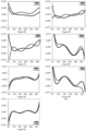


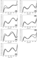
Classifications
-
- A—HUMAN NECESSITIES
- A61—MEDICAL OR VETERINARY SCIENCE; HYGIENE
- A61B—DIAGNOSIS; SURGERY; IDENTIFICATION
- A61B5/00—Measuring for diagnostic purposes; Identification of persons
- A61B5/0059—Measuring for diagnostic purposes; Identification of persons using light, e.g. diagnosis by transillumination, diascopy, fluorescence
- A61B5/0075—Measuring for diagnostic purposes; Identification of persons using light, e.g. diagnosis by transillumination, diascopy, fluorescence by spectroscopy, i.e. measuring spectra, e.g. Raman spectroscopy, infrared absorption spectroscopy
-
- A—HUMAN NECESSITIES
- A61—MEDICAL OR VETERINARY SCIENCE; HYGIENE
- A61B—DIAGNOSIS; SURGERY; IDENTIFICATION
- A61B5/00—Measuring for diagnostic purposes; Identification of persons
- A61B5/02—Detecting, measuring or recording for evaluating the cardiovascular system, e.g. pulse, heart rate, blood pressure or blood flow
- A61B5/0205—Simultaneously evaluating both cardiovascular conditions and different types of body conditions, e.g. heart and respiratory condition
-
- A—HUMAN NECESSITIES
- A61—MEDICAL OR VETERINARY SCIENCE; HYGIENE
- A61B—DIAGNOSIS; SURGERY; IDENTIFICATION
- A61B5/00—Measuring for diagnostic purposes; Identification of persons
- A61B5/02—Detecting, measuring or recording for evaluating the cardiovascular system, e.g. pulse, heart rate, blood pressure or blood flow
- A61B5/024—Measuring pulse rate or heart rate
- A61B5/02438—Measuring pulse rate or heart rate with portable devices, e.g. worn by the patient
-
- A—HUMAN NECESSITIES
- A61—MEDICAL OR VETERINARY SCIENCE; HYGIENE
- A61B—DIAGNOSIS; SURGERY; IDENTIFICATION
- A61B5/00—Measuring for diagnostic purposes; Identification of persons
- A61B5/103—Measuring devices for testing the shape, pattern, colour, size or movement of the body or parts thereof, for diagnostic purposes
- A61B5/11—Measuring movement of the entire body or parts thereof, e.g. head or hand tremor or mobility of a limb
- A61B5/1118—Determining activity level
-
- A—HUMAN NECESSITIES
- A61—MEDICAL OR VETERINARY SCIENCE; HYGIENE
- A61B—DIAGNOSIS; SURGERY; IDENTIFICATION
- A61B5/00—Measuring for diagnostic purposes; Identification of persons
- A61B5/145—Measuring characteristics of blood in vivo, e.g. gas concentration or pH-value ; Measuring characteristics of body fluids or tissues, e.g. interstitial fluid or cerebral tissue
- A61B5/1455—Measuring characteristics of blood in vivo, e.g. gas concentration or pH-value ; Measuring characteristics of body fluids or tissues, e.g. interstitial fluid or cerebral tissue using optical sensors, e.g. spectral photometrical oximeters
- A61B5/14551—Measuring characteristics of blood in vivo, e.g. gas concentration or pH-value ; Measuring characteristics of body fluids or tissues, e.g. interstitial fluid or cerebral tissue using optical sensors, e.g. spectral photometrical oximeters for measuring blood gases
-
- A—HUMAN NECESSITIES
- A61—MEDICAL OR VETERINARY SCIENCE; HYGIENE
- A61B—DIAGNOSIS; SURGERY; IDENTIFICATION
- A61B5/00—Measuring for diagnostic purposes; Identification of persons
- A61B5/45—For evaluating or diagnosing the musculoskeletal system or teeth
- A61B5/4519—Muscles
-
- A—HUMAN NECESSITIES
- A61—MEDICAL OR VETERINARY SCIENCE; HYGIENE
- A61B—DIAGNOSIS; SURGERY; IDENTIFICATION
- A61B5/00—Measuring for diagnostic purposes; Identification of persons
- A61B5/72—Signal processing specially adapted for physiological signals or for diagnostic purposes
- A61B5/7225—Details of analogue processing, e.g. isolation amplifier, gain or sensitivity adjustment, filtering, baseline or drift compensation
-
- G—PHYSICS
- G16—INFORMATION AND COMMUNICATION TECHNOLOGY [ICT] SPECIALLY ADAPTED FOR SPECIFIC APPLICATION FIELDS
- G16H—HEALTHCARE INFORMATICS, i.e. INFORMATION AND COMMUNICATION TECHNOLOGY [ICT] SPECIALLY ADAPTED FOR THE HANDLING OR PROCESSING OF MEDICAL OR HEALTHCARE DATA
- G16H40/00—ICT specially adapted for the management or administration of healthcare resources or facilities; ICT specially adapted for the management or operation of medical equipment or devices
- G16H40/60—ICT specially adapted for the management or administration of healthcare resources or facilities; ICT specially adapted for the management or operation of medical equipment or devices for the operation of medical equipment or devices
- G16H40/67—ICT specially adapted for the management or administration of healthcare resources or facilities; ICT specially adapted for the management or operation of medical equipment or devices for the operation of medical equipment or devices for remote operation
-
- A—HUMAN NECESSITIES
- A61—MEDICAL OR VETERINARY SCIENCE; HYGIENE
- A61B—DIAGNOSIS; SURGERY; IDENTIFICATION
- A61B2562/00—Details of sensors; Constructional details of sensor housings or probes; Accessories for sensors
- A61B2562/04—Arrangements of multiple sensors of the same type
-
- A—HUMAN NECESSITIES
- A61—MEDICAL OR VETERINARY SCIENCE; HYGIENE
- A61B—DIAGNOSIS; SURGERY; IDENTIFICATION
- A61B5/00—Measuring for diagnostic purposes; Identification of persons
- A61B5/02—Detecting, measuring or recording for evaluating the cardiovascular system, e.g. pulse, heart rate, blood pressure or blood flow
- A61B5/024—Measuring pulse rate or heart rate
- A61B5/02416—Measuring pulse rate or heart rate using photoplethysmograph signals, e.g. generated by infrared radiation
-
- A—HUMAN NECESSITIES
- A61—MEDICAL OR VETERINARY SCIENCE; HYGIENE
- A61B—DIAGNOSIS; SURGERY; IDENTIFICATION
- A61B5/00—Measuring for diagnostic purposes; Identification of persons
- A61B5/103—Measuring devices for testing the shape, pattern, colour, size or movement of the body or parts thereof, for diagnostic purposes
- A61B5/11—Measuring movement of the entire body or parts thereof, e.g. head or hand tremor or mobility of a limb
- A61B5/1107—Measuring contraction of parts of the body, e.g. organ or muscle
-
- A—HUMAN NECESSITIES
- A61—MEDICAL OR VETERINARY SCIENCE; HYGIENE
- A61B—DIAGNOSIS; SURGERY; IDENTIFICATION
- A61B5/00—Measuring for diagnostic purposes; Identification of persons
- A61B5/145—Measuring characteristics of blood in vivo, e.g. gas concentration or pH-value ; Measuring characteristics of body fluids or tissues, e.g. interstitial fluid or cerebral tissue
- A61B5/14542—Measuring characteristics of blood in vivo, e.g. gas concentration or pH-value ; Measuring characteristics of body fluids or tissues, e.g. interstitial fluid or cerebral tissue for measuring blood gases
-
- A—HUMAN NECESSITIES
- A61—MEDICAL OR VETERINARY SCIENCE; HYGIENE
- A61B—DIAGNOSIS; SURGERY; IDENTIFICATION
- A61B5/00—Measuring for diagnostic purposes; Identification of persons
- A61B5/145—Measuring characteristics of blood in vivo, e.g. gas concentration or pH-value ; Measuring characteristics of body fluids or tissues, e.g. interstitial fluid or cerebral tissue
- A61B5/14546—Measuring characteristics of blood in vivo, e.g. gas concentration or pH-value ; Measuring characteristics of body fluids or tissues, e.g. interstitial fluid or cerebral tissue for measuring analytes not otherwise provided for, e.g. ions, cytochromes
-
- A—HUMAN NECESSITIES
- A61—MEDICAL OR VETERINARY SCIENCE; HYGIENE
- A61B—DIAGNOSIS; SURGERY; IDENTIFICATION
- A61B5/00—Measuring for diagnostic purposes; Identification of persons
- A61B5/22—Ergometry; Measuring muscular strength or the force of a muscular blow
- A61B5/221—Ergometry, e.g. by using bicycle type apparatus
- A61B5/222—Ergometry, e.g. by using bicycle type apparatus combined with detection or measurement of physiological parameters, e.g. heart rate
-
- A—HUMAN NECESSITIES
- A61—MEDICAL OR VETERINARY SCIENCE; HYGIENE
- A61B—DIAGNOSIS; SURGERY; IDENTIFICATION
- A61B5/00—Measuring for diagnostic purposes; Identification of persons
- A61B5/68—Arrangements of detecting, measuring or recording means, e.g. sensors, in relation to patient
- A61B5/6801—Arrangements of detecting, measuring or recording means, e.g. sensors, in relation to patient specially adapted to be attached to or worn on the body surface
- A61B5/6813—Specially adapted to be attached to a specific body part
- A61B5/6823—Trunk, e.g., chest, back, abdomen, hip
-
- A—HUMAN NECESSITIES
- A61—MEDICAL OR VETERINARY SCIENCE; HYGIENE
- A61B—DIAGNOSIS; SURGERY; IDENTIFICATION
- A61B5/00—Measuring for diagnostic purposes; Identification of persons
- A61B5/68—Arrangements of detecting, measuring or recording means, e.g. sensors, in relation to patient
- A61B5/6801—Arrangements of detecting, measuring or recording means, e.g. sensors, in relation to patient specially adapted to be attached to or worn on the body surface
- A61B5/683—Means for maintaining contact with the body
- A61B5/6831—Straps, bands or harnesses
Definitions
- the present invention relates to a monitoring and evaluation method of muscle hemodynamic performance, in particular a monitoring and evaluation method based on the use of near infrared sensors (NIRS).
- NIRS near infrared sensors
- the object of the present invention is to provide a method and a muscle hemodynamic monitoring and evaluation system that allows to evaluate and analyze the performance of muscle tissues in an analytical way and a global way overall performance of all muscle tissues during a cyclical locomotor activity.
- Indirect calorimetry is a representation of the joint performance of all muscle tissues.
- this evaluation method doesn't allow to know what the performance of each one of the muscular tissues has been like.
- Blood Lactate [La +] measurements are also widely very used in the research and sports world to correlate them with locomotor performance, since certain levels and increases in Blood Lactate values are associated with certain work intensities.
- the closest method that allows to partially measure the performance of the muscular tissues during a Locomotor Activity or Cyclic Physical Activity is the use of electromyography, whether invasive or surface. However, this method only allows obtaining the electrical activation values of each muscle tissue (TM).
- the present invention refers to a method of monitoring and evaluating of muscle hemodynamic performance, in a non-invasive way, through the use of near-infrared spectroscopy (NIRS) devices, to establish the hemodynamic performance of multiple muscles tissues (TM s ) of simultaneously during a Locomotor Activity or Cyclic Physical Activity (AFM) determined.
- NIRS near-infrared spectroscopy
- the monitoring and evaluation method of the invention analyses three aspects of muscle hemodynamic performance which are:
- Oxidative capacity and blood delivery have a series of sub-factors that determine specific aspects of their activity, offering information on the level of performance of each TM individually and collectively, in addition to the link with other physiological systems.
- the method of the invention comprises in general the following differentiated parts:
- the invention refers to a Muscle Hemodynamic Monitoring and Evaluation Method that allows the evaluation and analysis of locomotor performance during AFC M , allowing to analysis and determination of the systemic or analytical physiological factors that limit or impede the perfect locomotor performance of human muscle tissues.
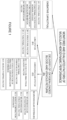
- Figure 1 shows the general scheme of all the factors that allows to evaluate and analyze.
- data capture is carried out, which refers to procedures prior to data recording of the evaluation and monitoring method of the invention.
- the processing system takes care of the data management stage, which includes downloading, synchronization, data filtering, and data analysis.
- the intensity or range of locomotor intensity equivalent to the Minimum Activation Threshold (U Amin ), the Aerobic Threshold (U Ae ) and the Anaerobic Threshold (U Ana ) that the user has developed during the AFC M will be established.
- Thresholds are obtaining from combination of all the data of SmO 2 % , ThB, ⁇ ThB, O 2 HHb, ⁇ O 2 HHb, HHb, ⁇ HHb of all TM M .
- the procedure for calculating the Thresholds, through the processing system, has got the following steps: 1. Filter and exclude all values obtained, calculated and/or recorded during all Rest Intervals (ID) or without AFC. 2. Filter and exclude all values obtained, calculated and/or recorded during the first minute of each work interval (IT). 3. Filter and exclude all the values obtained, calculated and/or registered when the value of locomotor intensity in the same time register is equivalent to "0". 4. Filter and exclude all the values obtained, calculated and / or registered when the value of locomotor movement frequency in the same time register is equivalent to "0". 5. Choose and perform at least one of the following procedures:
- the processing system coming up next determines if there are limitations on the performance of the subject to be analyzed and of what type these limitations are. To do this, a series of values and ranges of the measured and calculated variables are determined that indicate the presence of different types of limitations. The types of limitations that may exist and the steps to follow in determining the presence of each one in the subject's performance are explained below.
- the oxidative capacity is the potential of the muscular tissues to consume the oxygen delivered in the muscular capillaries and with the objective of producing an amount of adenosine triphosphate (ATP) necessary for the locomotor movement.
- ATP adenosine triphosphate
- the performance of the global muscle oxidative capacity is established, that is, the global or average level of the entire locomotor system, and at the same time the individual performance level of each muscle tissue is established. Since there are multiple factors that can affect to the ability of consume oxygen of only one muscle tissue while the consumption potential remains intact in the other muscle tissues.
- a perfect global or general muscle oxidative capacity occurs when each muscle tissue that participates in locomotor activity is capable of consuming all the oxygen delivered by the cardiovascular system.
- Factor (A1) is that factor that analyzes and evaluates the performance of the level of mitochondrial density and / or oxidative enzymes available to muscle tissues. Oxygen is consumed within the mitochondria and the enzymes participate in this process and establish the speed at which it is consumed, a low level of both means a low capacity to consume oxygen and produce high amounts of energy per unit of time. A limitation in this factor means a general limitation of oxidative capacity in practically almost all muscle fibers.
- the functional factor of oxidative capacity is that factor that analyzes and evaluates whether the muscle tissues have the potential or the capacity to consume large amounts of oxygen delivered by the cardiovascular system, but due to factors of general fatigue, the muscle tissues lose part or all its consumption potential. Once the general fatigue disappears, this limitation disappears, it is a temporary limitation of the performance of the oxidative capacity and it is observed in practically all the muscular tissues at the same time.
- the functional factor of the oxidative capacity due to Muscle Inhibition is that factor that analyzes each muscle tissue individually to assess whether the analyzed muscle tissue loses its potential or the ability to consume large amounts of oxygen temporarily due to a muscle inhibition. This factor is usually observed in isolated tissues, which lose their potential while the rest of the muscle tissues keep their oxygen consumption potential intact, unlike what happens in the functional factor due to general fatigue.
- the Neuromuscular factor of Oxidative Capacity is that factor that analyzes and evaluates whether the muscle tissues have the potential or the ability to consume large amounts of oxygen delivered by the cardiovascular system, but certain evaluated muscle tissues that participate in the activity locomotive, they do not, while the other muscular tissues do develop their potential.
- the pattern of muscle recruitment by the nervous system refers to the level of activation and participation in locomotor activity, a perfect muscle recruitment would mean that all the muscle tissues that participate in said movement have the same level of metabolic activation and therefore, the same muscle oxygen consumption.
- the level of performance of this aspect is determined by the ability of the nervous system to recruit and activate all muscle tissues symmetrically during locomotor movement.
- the nervous system is not efficient in muscle recruitment, it activates differently and to a greater or / or lesser degree the different muscle tissues involved in locomotor activity. It should be noted that when this happens, a symmetry is usually observed between muscle tissues and their contralateral muscle tissues in the hemodynamic and activation values.
- the biomechanical pattern refers to the physical movement carried out by the evaluated subject, any type of incorrect and/or inefficient biomechanical pattern may mean that the nervous system must recruit some muscle tissues to a greater or / or lesser extent than other muscle tissues that participate in locomotor activity to be able to cope with said alterations or inefficient biomechanical patterns.
- the Capacity to Deliver Oxygen-Loaded Blood Flow and the Venous Return is a performance performed jointly, dependently, harmonically and synchronized by the different vascular, muscular and nervous tissues together with the multiple organs of the body involved in gas exchange, the maintenance of blood pressure, supply and redistribution of oxygen-laden blood flow throughout the body, the level of metabolic activation of each tissue, and venous return during locomotor movement.
- the limiting factors for performance are divided according to the physiological system that interacts with some aspect of blood flow.
- the 3 systems into which the factors are divided are the pulmonary system, the cardiovascular system and the nervous system.
- the Structural Factor of the Pulmonary System is that factor that analyzes and evaluates if there is any type of limitation in the exchange of gases produced in the lung, negatively affecting and reducing the delivery of oxygen-charged haemoglobin to the muscle tissues.
- the Pulmonary Structural Factor indirectly represents the state and performance of the pulmonary structures involved in gas exchange (for example, the pulmonary alveoli). Any deficiency in these structures can affect to the uptake of oxygen O 2 and the expulsion of CO 2 and H 2 O from the bloodstream.
- This limitation is mainly observed in people with respiratory diseases diagnosed as COPD, people with 1 lung, asthmatics, or smokers generally.
- the Pulmonary Functional Factor (Respiratory Muscles) is that factor that analyzes and evaluates if there is any type of limitation in the exchange of gases in the lungs produced by the inefficiency and/or incapacity of the muscular tissues in charge of the biomechanical phases of respiration [inspiration and expiration].
- the effects are the same as the Pulmonary System Structural Factor, but with a different limiting cause.
- the magnitude of the limitation depends on the level of deconditioning or inefficiency of performance by the respiratory muscle tissues. Even any muscle blockage or "muscle contracture" in muscle tissues that limits the range of motion of the rib cage can prevent the maximum volume of oxygen introduced into the lungs from being generated.
- the Performance Factor of Analytical Delivery of Blood Flow during exercise is that factor that analyzes and evaluates cardiovascular performance in each of the muscle tissues that participate in locomotor activity. This factor analyzes how the cardiovascular system satisfies the demands of blood flow from the muscle and determines how the characteristics of the flow delivered to each muscle are.
- the delivery of blood flow is totally different in each of the muscle tissues, for that reason the characteristics of blood flow are analyzed individually, allowing to identify if there is some type of hierarchy of preference between muscle tissues in terms of the delivery of blood
- vasodilation occurs due to various mechanical, nervous and metabolic factors. If this vasodilation occurs excessively, it can "threaten" the systemic regulation of blood pressure throughout the body, for that reason the sympathetic nervous system does a vascular vasoconstriction to maintain blood pressure and blood flow levels in order to maintain regular oxygen supply to the brain and vital organs (Functional Sympatholysis).
- Regulation of blood flow to skeletal muscle is closely linked to metabolic oxygen demand and with a change in oxygen requirement leading to a proportional change in blood flow.
- the precise control of the regulation of blood flow serves to minimize the work of the heart, while ensuring an adequate supply of oxygen to the working muscles.
- the need for this precise control of blood flow to the muscle becomes apparent when you consider that active skeletal muscle comprises about -40% of body mass and that muscle-specific blood flow can increase nearly 100-fold from rest to intense exercise.
- the heart can only supply a fraction of the active muscles with maximum blood flow and during high intensity exercises involving greater muscle mass, vascular conductance has to be well regulated or pressure blood pressure could drop.
- This factor evaluates and analyzes the performance of Functional Sympatholysis, that is, the performance of the nervous system on cardiovascular function in the redistribution of blood flow.
- Functional Sympatholysis that is, the performance of the nervous system on cardiovascular function in the redistribution of blood flow.
- rest intervals are used, since once the exercise ceases, the vasoconstrictive effect of the nervous system ceases, but the opposing vasodilator effects at the muscular level remain active as they are slower. This allows to analyze the magnitude of their performance during the exercise that was previously carried out.
- the evolution of cardiovascular performance in the delivery/demand of blood flow of a muscle tissue can be evaluated. This factor analyzes the evolution of this performance and for this a comparison is made between the values of the analyzed muscle tissue, in the rest intervals analyzed.
- the Muscle Blood Flow Pumping Factor is that factor that analyzes and evaluates the performance of each muscle tissue during locomotor movement to perform muscle contraction and compress the blood vessels located in said muscle tissues. This compression of the blood vessels causes the venous return of blood flow to the heart.
- Each muscle tissue must be able to generate sufficient mechanical stress on the blood vessels to drive blood flow through the venous system.
- the collective performance of this factor is important to maintain efficient venous return.
- the cardiovascular system is a closed circuit system, any alteration of the maximum venous return potential affects the entire cardiovascular system, because if the maximum volume of blood that returns to the heart through the venous return decreases, cardiac filling will decrease, then the stroke volume will be lower, and later the arterial pressure will drop, since the volume of blood ejected by the heart will be lower.
- the Neuromuscular Activation Factor (Intermuscular Coordination) is that factor that analyzes and evaluates the performance of the nervous system to activate each muscle tissue during locomotor movement. This factor includes the analysis, evaluation and comparison between the different levels of metabolic activation generated by the nervous system between the muscular tissues that participate in locomotor activity (Intermuscular Coordination).
- a perfect or efficient neuromuscular activation of all muscle tissues is one in which all muscle tissues involved in locomotor activity have the same level of metabolic activation to cope with the demands of locomotor movement.
- an optimal (efficient) activation range is established to be able to assess the activation level of each muscle tissue individually.
- a muscle tissue that is below or above said optimal activation zone can be interpreted that that tissue has a higher u / or lower muscle activation and therefore the metabolic efficiency of the set of muscle tissues decreases.
- a greater symmetry in the levels of muscle activation during locomotor work translates into a lower energy cost to cope with said locomotor work/movement, on the other hand, a greater asymmetry of the whole and/or a muscle tissue means a higher energy cost for cope with locomotor work/movement [Running Economy].
- the Neurovascular Structural Factor (Speed and Power of Muscle Contraction) is that factor that analyzes and evaluates the potential of [vasodilation vs vasoconstriction] in each muscle tissue evaluated.
- this nerve potential When the action potential is produced in the muscle tissue to produce the muscle contraction necessary for locomotor movement, this nerve potential also has an inhibitory effect and some chain responses that cause an inhibition of the vasoconstrictive effect of the sympathetic nervous system. On the other hand, it causes marked vasodilation in the arteriolar tissues close to the place where the action potential is produced.
- vasodilation in muscle tissues is directly correlated with the speed of muscle contraction and / or the level of activation of said muscle tissue.
- Muscle tissue must have an optimal level of vasodilation to allow optimal oxygen-laden blood flow to arrive. Excessive vasodilation may mean that excessively vasodilated muscle tissue receives a greater volume of blood flow, more than is necessary to meet the metabolic oxygen demands that muscle tissue requires. This fact causes an inefficiency in the delivery of oxygen-laden blood flow by not being able to deliver this excess blood flow to other muscle tissues that do require it, causing a deficit in the delivery of oxygen-laden blood flow.
- the Muscle Contraction Speed Factor is that factor that analyzes and evaluates the frequency at which muscle contractions occur during locomotor activity.
- the nervous system produces an electrical impulse that causes alterations in cellular metabolism to generate the contraction of muscle fibers.
- Said electrical impulse also has an inhibiting effect on the local vasoconstrictor receptors of the arteriolar network of the muscle.
- a high production of these impulses produces a high inhibition of vasoconstrictors and consequently increases the vasodilation of the arteries in the TM.
- an excessive vasodilation produces an excess delivery of blood flow, whereas a low frequency of electrical impulse discharge in the muscle will produce a low vasodilation and a greater vasoconstriction, producing an arterial occlusion mediated by the sympathetic nervous system.
- this factor is in charge of evaluating muscle performance as a whole to establish which muscle contraction frequency (FCM) or Muscle Contraction Frequency Range (R-FCM) is optimal for the hemodynamic performance of the cardiovascular system.
- FCM muscle contraction frequency
- R-FCM Muscle Contraction Frequency Range
- the monitoring method of the invention described makes it possible to evaluate and monitor the muscle hemodynamic performance of all TM S M analytically, globally and both at the same time, during a AFC.
- This evaluation includes TM S M that are not directly involved in locomotor work, such as the muscular tissues responsible for respiratory movements.
- the method of the invention allows the generation of an individualized physiological profile, as it offers complete information on the factors that affect or limit the analytical hemodynamic performance of each TM M and, at the same time, the general hemodynamic performance of all TM S M as a whole.
- the physiological factors that limit the performance of subject are established, in a very analytical way, the physiological factors that limit the performance of subject.
- the method of the invention allows the analysis to be carried out in the training sessions themselves without the need to make any modification of the AFC that the subject is developing, or any specific protocol, or any environmental or environmental conditions.
- the usual evaluation methods generally require a controlled environment, in laboratories or closed places, moving away from the reality of the AFC developed by the majority of subjects.
- the method of the invention also makes it possible to quantify the running economy or efficiency of work of TM S M from an analytical physiological point of view. By analyzing the individual performance of each TM M separately, then jointly with other TM S M , it allows quantifying the running economy or efficiency of work to be able define it, as well as establishing the specific tissues and / or factors that positively affect and/or negatively to the economy of work.
- the evaluation methods up to now, measured and quantified the efficiency of locomotor performance from general values of the whole body such as the analysis of metabolic gases or blood lactate concentrations, or using external variables such as power development values or measurements of strength in exercises.
- the performance performed by each of the muscle tissues is directly evaluated and at the same time the global work, allowing to identify the muscle tissues that are negatively affecting the economy of work and, at the same time, evaluate how the performance is being in the set of muscular tissues.
- the method of the invention makes it possible to establish action or training protocols to specifically improve said factors optimally and improve locomotor performance.
- the invention also refers to a monitoring and evaluation system of the physical performance of a subject comprising:
- ThB calculated from the values of ThB of each TM M can be observed.
- Table 3. Equation of the Trend Line of
- L Y ⁇ 5 E ⁇ 14 x 6 + 7 E ⁇ 11 x 5 ⁇ 4 E ⁇ 08 x 4 + 1 E ⁇ 05 x 3 ⁇ 0,0016 x 2 + 0,1291 x + 8,6505 RF
- ⁇ ThB calculated from the values of ⁇ ThB of each TM M can be observed.
- Table 4. Equation of the Trend Line of
- O 2 HHb calculated from the values of O 2 HHb of each TM M can be observed.
- L Y ⁇ 3 E ⁇ 12 x 6 + 3 E ⁇ 09 x 5 ⁇ 2 E ⁇ 06 x 4 + 0,0004 x 3 ⁇ 0,0531 x 2 + 3,614 x ⁇ 88,785 RF
- R Y ⁇ 3 E ⁇ 12 x 6 + 4 E ⁇ 09 x 5 ⁇ 2 E ⁇ 06 x 4 + 0,0005 x 3 ⁇ 0,0609 x 2 + 4,0896 x ⁇ 99,856 Represented in Figure 24
- VL L Y ⁇ 3 E ⁇ 12 x 6 + 4 E ⁇ 09 x 5 ⁇ 2 E ⁇ 06 x 4 +
- Equation of the Trend Line IYIHHb calculated from the values of HHb of each TM M can be observed.
- Table 6 Equation of the Trend Line of
- ⁇ O 2 HHb calculated from the values of ⁇ O 2 HHb of each TM M can be observed.
- Table 7. Equation of the Trend Line of
- ⁇ HHb calculated from the values of ⁇ HHb of each TM M can be observed.
- Table 9 Table 10 and Table 11, the calculated values of
- the 1st General Change ( p ) is equals the Minimum Activation Threshold (U Amin ), the 2nd General Change ( p ) is equals the Aerobic Threshold (U Ae ) and the 3rd General Change ( p ) is equals the Threshold Anaerobic (U ANA ), of each TM M .
- Table 30 General changes in trend and physiological thresholds of each TM M .
- NS CSV equivalent to the values of CSV CSV Symmetry Level (NS CSV ) SmO 2 % O 2 HHb - HHb ⁇ O2HHb - ⁇ HHb Perfect ⁇ 0,01 ⁇ 0,001 ⁇ 0,01 Optimum > 0,01 ⁇ 0,05 > 0,001 ⁇ 0,005 > 0,01 ⁇ 0,05 Minimal > 0,05 ⁇ 0,20 > 0,005 ⁇ 0,02 > 0,05 ⁇ 0,2 Asymmetry > 0,20 > 0,02 > 0,2 - There is a Functional Factor Limitation due to Muscular Inhibition of Oxidative Capacity in the Left Rectus Femoris (RF L) because it meets the established criteria of Factor (A3) that can be determined:
- muscle performance factors do not meet the criteria established by each factor to determine that any TM M or all of them develop at least one limitation of said factors:
Landscapes
- Health & Medical Sciences (AREA)
- Life Sciences & Earth Sciences (AREA)
- Engineering & Computer Science (AREA)
- Physics & Mathematics (AREA)
- Biomedical Technology (AREA)
- Public Health (AREA)
- General Health & Medical Sciences (AREA)
- Medical Informatics (AREA)
- Heart & Thoracic Surgery (AREA)
- Pathology (AREA)
- Molecular Biology (AREA)
- Surgery (AREA)
- Animal Behavior & Ethology (AREA)
- Biophysics (AREA)
- Veterinary Medicine (AREA)
- Physiology (AREA)
- Cardiology (AREA)
- Oral & Maxillofacial Surgery (AREA)
- Dentistry (AREA)
- Spectroscopy & Molecular Physics (AREA)
- Pulmonology (AREA)
- Signal Processing (AREA)
- Orthopedic Medicine & Surgery (AREA)
- Rheumatology (AREA)
- Primary Health Care (AREA)
- Epidemiology (AREA)
- General Business, Economics & Management (AREA)
- Optics & Photonics (AREA)
- Power Engineering (AREA)
- Business, Economics & Management (AREA)
- Artificial Intelligence (AREA)
- Computer Vision & Pattern Recognition (AREA)
- Psychiatry (AREA)
- Investigating Or Analysing Biological Materials (AREA)
- Acyclic And Carbocyclic Compounds In Medicinal Compositions (AREA)
- Emergency Medicine (AREA)
- Obesity (AREA)
Abstract
Description
- The present invention relates to a monitoring and evaluation method of muscle hemodynamic performance, in particular a monitoring and evaluation method based on the use of near infrared sensors (NIRS).
- The object of the present invention is to provide a method and a muscle hemodynamic monitoring and evaluation system that allows to evaluate and analyze the performance of muscle tissues in an analytical way and a global way overall performance of all muscle tissues during a cyclical locomotor activity.
- Nowadays, a lot of many assessment methods and devices, both invasive and non-invasive, are used to assess the physiological performance of the human body in a multitude of locomotor movements and in a wide variety of conditions. One of the most used methods to evaluate the physiological performance during exercise is the measurement of indirect calorimetry, from which derive variables relating to the exchange of gases in the human body.
- Indirect calorimetry is a representation of the joint performance of all muscle tissues. On the other hand, this evaluation method doesn't allow to know what the performance of each one of the muscular tissues has been like.
- Blood Lactate [La +] measurements are also widely very used in the research and sports world to correlate them with locomotor performance, since certain levels and increases in Blood Lactate values are associated with certain work intensities.
- The closest method that allows to partially measure the performance of the muscular tissues during a Locomotor Activity or Cyclic Physical Activity (AFM) is the use of electromyography, whether invasive or surface. However, this method only allows obtaining the electrical activation values of each muscle tissue (TM).
- Currently athletes and coaches use one to three NIRS devices to evaluate the physiological performance of an athlete in a physical activity. In these studies, only Muscular Oxygen Saturation (SmO2) and Capillary Hemoglobin (ThB) values are used to establish in a very generic way what the athlete's performance limitation has been during exercise. Thus, the data obtained from one or two muscle tissues are used to determine that the subject evaluated has a general physiological limitation of this nature in his muscles, without taking into account the performance of other muscle tissues.
- Likewise, state-of-the-art studies use only 1 or 2 NIRS devices to evaluate highly analytical aspects of the hemodynamic performance (%SmO2, ThB, O2HHb, HHb) of one or two muscle tissues (mainly: deltoid, vast lateral & rectus femoris). Data obtained from muscle tissues are used to represent the hemodynamic performance of all muscle tissues, assuming that there is symmetry in all active tissues.
- The present invention refers to a method of monitoring and evaluating of muscle hemodynamic performance, in a non-invasive way, through the use of near-infrared spectroscopy (NIRS) devices, to establish the hemodynamic performance of multiple muscles tissues (TMs) of simultaneously during a Locomotor Activity or Cyclic Physical Activity (AFM) determined.
- In general, the monitoring and evaluation method of the invention analyses three aspects of muscle hemodynamic performance which are:
- 1. The Physiological Thresholds: From the monitoring and evaluation of the redirection of blood flow developed in the TM, the Minimum Activation Threshold (UAmin), the Aerobic Threshold (UAe) and the Anaerobic Threshold (UAna) can be established.
- 2. The Muscle Oxidative Capacity: The performance in the capacity that has each TM for consuming the oxygen that is delivered by the cardiovascular system for production of the energy necessary to develop locomotor movement.
- 3. The Delivery of Oxygen Loaded and Oxygen Discharged Blood: The performance in the capacity to deliver the oxygen-loaded blood necessary for TMs to be able to consume it and produce the energy necessary for locomotor movement. It also includes hemodynamic performance in the ability to maintain blood flow and venous return necessary for each work intensity.
- Each one of these aspects determine the general hemodynamic performance of each muscle tissue and at the same time report a collective performance of the muscular system as a whole. Oxidative capacity and blood delivery have a series of sub-factors that determine specific aspects of their activity, offering information on the level of performance of each TM individually and collectively, in addition to the link with other physiological systems.
- The method of the invention comprises in general the following differentiated parts:
- 1. Capture of hemodynamic data during locomotor performance: while the user that is evaluated, perform an AFM with certain characteristics, the NIRS devices are adhered to the human skin in each of the TMs involved in AFM, additionally they can be included other TMs involved in the inspiration and expiration phases. The hemodynamic values are registered by these devices and also the heart rate (HR) values can be registered with a monitor of HR. Also, record data on external locomotor performance developed during AFC, such as power or cadence data.
- 2. Data Management: Doing a process of downloading, synchronization, linking and filtering of the data obtained is carried out, through a data processing system.
- 3. Analysis and Evaluation of the Hemodynamic Data Obtained During Monitored Locomotor Activity or Cyclic Physical Activity (AFCM): The hemodynamic data obtained with the NIRS devices and the other devices during the AFCM are evaluated and analysed analytically for each TM, and jointly for to establish which has been the physiological performance of the all TMs during the AFCM, the physiological thresholds of each TM, the general physiological thresholds, the performance of each subfactor and the physiological factors limiting muscle hemodynamic performance during the developed AFCM.
- The invention refers to a Muscle Hemodynamic Monitoring and Evaluation Method that allows the evaluation and analysis of locomotor performance during AFCM, allowing to analysis and determination of the systemic or analytical physiological factors that limit or impede the perfect locomotor performance of human muscle tissues.
Figure 1 shows the general scheme of all the factors that allows to evaluate and analyze. - In the first place, data capture is carried out, which refers to procedures prior to data recording of the evaluation and monitoring method of the invention.
- 1. The evaluation and monitoring method comprises a first stage of providing the subject to be evaluated of:
- ∘ Two or more near infrared sensors (NIRS).
- ∘ One Heart Rate (HR) monitor.
- ∘ One physical activity monitor or data recording device.
- ∘ One intensity meter or device (GPS, power meter, ...).
- 2. The NIRS are placed or adhered on the muscle tissues (TM) that will be evaluated and will participate in the Monitored Locomotor Activity or Cyclic Physical Activity (AFMM).
Likewise, the HR band will be placed on the subject's chest and any other monitor, devices and/or intensity and/or locomotor and/or physiological performance meter that requires it to obtain data will be placed or added. - 3. The data recording of all devices and activity monitors begins, minimally from the start of the AFM.
- The AFMM comprises one or more of the following characteristics:
- ∘ The subject to be evaluated will carry out a AFCM, such as running, swimming, pedalling, rowing, ...
- ∘ The devices record the data they capture and/or monitor during AFCM.
- ∘ The activity monitor records the full-time scale from the beginning to the end of the AFCM, including the multiple intervals of work and/or rest if performed.
- ∘ Complementary and/or necessary tools can be used for the development of AFCM.
- ∘ The data recording frequency of each device must be less than 6 seconds.
- ∘ The AFCM can be continuous or intervallic.
- ∘ The AFCM can be of stable, incremental, decreasing or variable locomotive intensity.
- ∘ The AFCM may or may not include a warm-up/prior preparation, and if it does not include it, the AFCM may contain a warm-up exercise prior to monitoring without the need to be recorded.
- ∘ The minimum number of records for each device will be equivalent to the minimum number of records to be able to generate the trend line of the variables that the device is monitoring.
- ∘ The characteristics of locomotor exercise (volume, duration, density, intensity, number of intervals, intensity of each interval, properties of the environment, ...) will depend on the physiological factor or factors of muscle performance that want to be evaluated, having a composition, structure and own characteristics in each case.
- ∘ External accessories or materials that participate in the locomotive activity may be introduced, such as a bicycle, a canoeing paddle or skis.
- The processing system takes care of the data management stage, which includes downloading, synchronization, data filtering, and data analysis.
- Thus, once the AFCM is finished, the following steps will be carried out:
- 1. Download all the data from each device with his temporary record of each value. The values downloaded by each device:
- a. NIRS: Muscular Oxygen Saturation (% - SmO2%) and Capillary Hemoglobin (g/dL - ThB).
- b. Heart Rate Monitor: Heart Rate (bpm - HR)
- c. Activity Monitor and/or computing device: temporal scale of AFCM
- d. Intensity device or monitor: Power (Watts) / Speed (Km/h) / Pace (min/Km) / Any locomotor intensity measurement
- e. External locomotor performance devices and/or monitors: Cadence (rpm) / Accelerometer / Pedometer / Any other type of device that provides data on external locomotor performance
- f. Devices and/or monitors of Physiological Locomotor Performance: Metabolic gas analyzers (VO2/CO2), lactate meters, thermal imaging cameras ...
- 2. Sync, link and pair all values on a single grouped data timescale starting from the timescale collected by the activity monitor during AFCM
- 3. Calculate the values for each Monitored Muscle Tissue (TMM) that participate in the AFCM from the recorded data of SmO2% and ThB of:
- ∘ Oxygen-Charged Capillary Hemoglobin - g/dL (O2HHb) % (SmO2) * g/dL (ThB) = g/dL (O2HHb)
- ∘ Oxygen Discharged Capillary Hemoglobin - g/dL (HHb) g/dL (ThB) - g/dL (O2HHb) = g/dL (HHb)
- ∘ Muscle Blood Flow of Muscle Hemoglobin - g/dL/s (ΦThB). [g/dL (ThB) * (HR)] / 60 = g/dL/seg (ΦThB)
- ∘ Muscular Blood Flow of Oxygen-Charged Hemoglobin - g/dL/s (ΦO2HHb). [g/dL (O2HHb) * (HR)] / 60 = g/dL/seg (ΦO2HHb)
- ∘ Muscular Blood Flow of Oxygen Discharged Hemoglobin - g/dL/s (ΦHHb). [g/dL (HHb) * (HR)] / 60 = g/dL/seg (ΦHHb)
- 4. Filter and exclude the data obtained erroneously and/or by registration error by the devices during AFCM. Exclude the data that are not within the following ranges and all the data obtained from the calculation of any of them:
- a. SMO2% [Between 1% SmO2 and 99% SmO2]
- b. ThB [Between 9.5 g/dL and 14,9 g/dL]
- c. HR [Between 40ppm and 230ppm]
- 5. Filter and exclude the data that present a difference greater than that established in the following parameters, between the temporary records of the same previous and subsequent value, and all the data obtained from the calculation of any of them will also be excluded:
- a. Difference of SmO2% [> ±10% SmO2%]
- b. Difference of ThB [> ±0.3 g/dL]
- c. Difference of HR [> ±7ppm]
- Then, through the processing system, an analysis and an evaluation of the data obtained during the AFCM is carried out.
- Previously to the analysis of the physiological factors, the intensity or range of locomotor intensity equivalent to the Minimum Activation Threshold (UAmin), the Aerobic Threshold (UAe) and the Anaerobic Threshold (UAna) that the user has developed during the AFCM will be established.
- To be able to establish each of the thresholds mentioned, it will require that intensities above these thresholds have been developed in the AFCM, in order to be monitored.
- Previous calculating the physiological thresholds, the trend line of each value obtained and/or calculated, for each TMM will be established.
- Thus, it proceeds to perform, through the processing system, an analysis and evaluation of physiological thresholds and the calculation of a trend line of the values obtained.
- To the Physiological Thresholds are obtaining from combination of all the data of SmO2 %, ThB, ΦThB, O2HHb, ΦO2HHb, HHb, ΦHHb of all TMM. The procedure for calculating the Thresholds, through the processing system, has got the following steps:
1. Filter and exclude all values obtained, calculated and/or recorded during all Rest Intervals (ID) or without AFC.
2. Filter and exclude all values obtained, calculated and/or recorded during the first minute of each work interval (IT).
3. Filter and exclude all the values obtained, calculated and/or registered when the value of locomotor intensity in the same time register is equivalent to "0".
4. Filter and exclude all the values obtained, calculated and / or registered when the value of locomotor movement frequency in the same time register is equivalent to "0".
5. Choose and perform at least one of the following procedures: - Procedure A
- A1. Calculate the statistical median value (

- A2. Establish the Trend Line (LinTrend) of the median values (


- A1. Calculate the statistical median value (
- Procedure B
- B1. Calculate the statistical average value (
Y ) of the values of SmO2 %, ThB, ΦThB, O2HHb, ΦO2HHb, HHb, ΦHHb, of each TMM, during AFCM, in each INTTL or R- INTTL , which participates in the AFCM. - B2. Establish the LinTrend of the average values (
Y -INTTL) or (Y -R-INTTL) obtained fromY SmO2 %,Y ThB,Y ΦThB,Y O2HHb,Y ΦO2HHb,Y HHb andY ΦHHb, in each TMM.
- B1. Calculate the statistical average value (
- Procedure C
C1. Establish the LinTrend (Value/INTTL) or (Value/R-INTTL), from all filtered values of SmO2 %, ThB, ΦThB, O2HHb, ΦO2HHb, HHb, ΦHHb, in each TMM. - To set whether a set of values | Y |SmO2 %, | Y |ThB, | Y |ΦThB, | Y |O2HHb, | Y |ΦO2HHb, | Y |HHb and/or | Y |ΦHHb, between two INTTL or two R- INTTL , of at least two TMS M have some level of symmetry or asymmetry, the following procedure must be carried out:
- Calculate, analyze and determine the CSV of the values of | Y |SmO2 %, | Y |ThB, | Y |ΦThB, | Y |O2HHb, | Y |ΦO2HHb, | Y |HHb or | Y |ΦHHb, between two INTTL or two R- INTTL determined, between at least two determined TMs m:
- Establish the Symmetry Level (NSCSV) from the CSV value calculated from the values | Y |SmO2 %, | Y |ThB, | Y |ΦThB, | Y |O2HHb, | Y |ΦO2HHb, | Y |HHb or | Y |ΦHHb, between two INTTL or two R- INTTL determined, between at least two TMS M determined:Symmetry Level (NSCSV) CSV SmO2 % O2HHb - HHb ΦO2HHb - ΦHHb Perfect ≤ 0,01 ≤ 0,001 ≤ 0,01 Optimum > 0,01 ≤ 0,05 > 0,001 ≤ 0,005 > 0,01 ≤ 0,05 Minimal > 0,05 ≤ 0,20 > 0,005 ≤ 0,02 > 0,05 ≤ 0,2 Asymmetry > 0,20 > 0,02 > 0,2 - To establish whether the trend of the values | Y |SmO2 %, | Y |O2HHb, | Y |ΦO2HHb, | Y |HHb and/or | Y |ΦHHb, between two INTTL or two R- INTTL determined, of a TMM have some level of symmetry or asymmetry with the trend of the values | Y |SmO2 %, | Y |O2HHb, | Y |ΦO2HHb, | Y |HHb and/or | Y |ΦHHb, between two INTTL or two R- INTTL determined, of at least one other TMM or a set of TMS M, the following procedure must be carried out:
- Calculate, analyze and determine the slope-trend(p) | Y | of at | Y |SmO2 %, | Y |O2HHb, | Y |ΦO2HHb, | Y |HHb and/or | Y |ΦHHb, between two INTTL or two R-INTTL determined, of at least two TMS M determined:
(p) is the slope-trend; |Y|1 the determined value of SmO2%, O2HHb, ΦO2HHb, HHb o ΦHHb, of the 1ST LNTTL or R-INTTL determined and |Y|2 of the 2nd INTTL or R-INTTL determined; |X| 1 is the 1ST LNTTL or R-INTTL and |X| 2 the 2nd INTTL or R-INTTL determined.
- Calculate, analyze and establish the Coef-( p ) of(p) | Y |SmO2 %,(p) | Y |O2HHb,( p ) | Y |ΦO2HHb,( p ) | Y |HHb and/or( p ) | Y |ΦHHb between two INTTL ortwo R-INTTL determined, of one TMM determined with respect to the trend of the values( p ) | Y |SmO2 %,( p ) | Y |O2HHb,( p ) | Y |ΦO2HHb,( p ) | Y |HHb and/or( p ) | Y |ΦHHb of another TMM or a set of trends of values(p) | Y |SmO2 %,( p ) | Y |O2HHb,( p ) | Y |ΦO2HHb,( p ) | Y |HHb and/or( p ) | Y |ΦHHb of two or more TMS M determined:

( p ) | Y | is the slope-trend of the analyzed TMM.
- Establish the Symmetry Level (NS Coef-(p) ) from the calculated value of Coef-( p ) ( p ) | Y |SmO2 %,( p ) | Y |O2HHb,( p ) | Y |ΦO2HHb,( p ) | Y |HHb o( p ) | Y |ΦHHb of the analyzed TMM:Symmetry Level (NS Coef-(p) ) Coef- (p) SmO2 % O2HHb - HHb ΦO2HHb- ΦHHb Perfect ≤ 0,01 ≤ 0,001 ≤ 0,01 Optimum > 0,01 ≤ 0,05 > 0,001 ≤ 0,005 > 0,01 ≤ 0,05 Minimal > 0,05 ≤ 0,15 > 0,005 ≤ 0,015 > 0,05 ≤ 0,15 Asymmetry > 0,15 > 0,015 > 0,15 - 16. The processing system coming up next determines if there are limitations on the performance of the subject to be analyzed and of what type these limitations are. To do this, a series of values and ranges of the measured and calculated variables are determined that indicate the presence of different types of limitations. The types of limitations that may exist and the steps to follow in determining the presence of each one in the subject's performance are explained below.
- The oxidative capacity is the potential of the muscular tissues to consume the oxygen delivered in the muscular capillaries and with the objective of producing an amount of adenosine triphosphate (ATP) necessary for the locomotor movement.
- When evaluating the hemodynamic performance, the performance of the global muscle oxidative capacity is established, that is, the global or average level of the entire locomotor system, and at the same time the individual performance level of each muscle tissue is established. Since there are multiple factors that can affect to the ability of consume oxygen of only one muscle tissue while the consumption potential remains intact in the other muscle tissues.
- A perfect global or general muscle oxidative capacity occurs when each muscle tissue that participates in locomotor activity is capable of consuming all the oxygen delivered by the cardiovascular system.
- On the contrary, limitations can occur with respect to the maximum potential of oxidative capacity when in at least one, a group or all the muscular tissues do not express the maximum capacity or potential to consume all the oxygen delivered by the cardiovascular system.
- Factor (A1) is that factor that analyzes and evaluates the performance of the level of mitochondrial density and / or oxidative enzymes available to muscle tissues. Oxygen is consumed within the mitochondria and the enzymes participate in this process and establish the speed at which it is consumed, a low level of both means a low capacity to consume oxygen and produce high amounts of energy per unit of time. A limitation in this factor means a general limitation of oxidative capacity in practically almost all muscle fibers.
- To establish that there is a Limitation in Factor A1, the following steps and criteria must be met:
- Evaluate the value of | Y |SmO2 % in each INTTL or R-INTTL , INTTL greater than or equal to UAmin and less than or equal to UAna.
- Calculate, compare, evaluate and establish the Coefficient of Symmetry between Values (CSV) and the Level of Symmetry (NSCSV) between | Y |SmO2 %, | Y |O2HHb and | Y |ΦO2HHb of each TMM and his Contralateral Muscle Tissue Monitored (TMCM), in each INTTL or R-INTTL INTTL greater than or equal to UAmin and less than or equal to UAna.
- Calculate, compare and evaluate the General Trend of the Values (TGV [
( p ) ]) | Y |SmO2 %, | Y |ΦO2HHb and | Y |O2HHb, of all TMS M, in the R-INTTL (UAmin - UAe) and (UAe - UAna). - Calculate, compare and establish the lowest value of Coef-
( p ) and the equivalent NS Coef-(p) of(p) | Y |SmO2 %,(p) | Y |ΦO2HHb and(p) | Y |O2HHb, between the combination of at least 70-75% of the TMS M, in the R-INTTL (UAmin - UAe) and (UAe - UAna). - Determine that the following criteria are met to establish a limitation in Factor (A1):
- 1. The value of | Y |SmO2 % in each INTTL or R-INTTL INTTL greater or equal than UAmin and less than or equal to UAna, is ≥70% SmO2%, in at least 70-75% of TMS M.
- 2. The values of | Y |SmO2 %, | Y |O2HHb and | Y |ΦO2HHb of each TMM and TMCM, have at least one optimal symmetry, in each INTTL or R-INTTL greater than or equal to UAmin and less than or equal to UAna, in at least the 70-75% of TMS M.
- 3. The TGV of de
(p) | Y |SmO2 %,(p) | Y |ΦO2HHb and(p) | Y |O2HHb is symmetric between the combination of at least 70-75% of TMS M, in the R-INTTL (UAmin-UAe) and (UAe - UAna). - 4. The TGV of de
(p) | Y |SmO2 %,(p) | Y |ΦO2HHb and(p) | Y |O2HHb is symmetric between each TMM and his TMCM, in at least 80-85% of TMS M, in the R-INTTL (UAmin - UAe) and (UAe - UAna).
- The functional factor of oxidative capacity is that factor that analyzes and evaluates whether the muscle tissues have the potential or the capacity to consume large amounts of oxygen delivered by the cardiovascular system, but due to factors of general fatigue, the muscle tissues lose part or all its consumption potential. Once the general fatigue disappears, this limitation disappears, it is a temporary limitation of the performance of the oxidative capacity and it is observed in practically all the muscular tissues at the same time.
- To establish a Limitation on Factor (A2) the following steps and criteria must be met:
- Evaluate the values of | Y |SmO2 %, | Y |O2HHb and | Y |ΦO2HHb of each TMM, in each INTTL or R-INTTL greater than or equal to UAmin.
- Calculate and evaluate the difference of SmO2% between the value of | Y |SmO2 % of each TMM and his TMCM, in each INTTL or R-INTTL greater than or equal to UAmin.
- Compare, evaluate and determine the CSV and NSCSV between the values of | Y |SmO2 %, | Y |ΦO2HHb and | Y |O2HHb of each TMM and his TMCM, in each INTTL or R-INTTL greater than or equal to UAmin.
- Calculate, compare and evaluate the TGV [
( p ) of | Y |SmO2 %, | Y |ΦO2HHb and | Y |O2HHb of all TMS M, in the R-INTTL (UAmin - UAe) and (UAe - UAna). - Calculate, compare and establish the lowest value of Coef-
( p ) and the equivalent NS Coef-(p) of( p ) | Y |SmO2 %,( p ) | Y |ΦO2HHb and( p ) | Y |O2HHb, between the combination of at least 50-55% of the TMS M, in the R-INTTL (UAmin - UAe) and (UAe - UAna). - Determine that the following criteria are met to establish a limitation in Factor (A2):
- 1. The difference between the value of | Y |SmO2 % of each TMM and his TMCM is >5% SmO2%, in the 95% of INTTL or R-INTTL greater than or equal to UAmin, in at least the 70-75% of TMS M.
- 2. The value of | Y |SmO2 % is ≥55% SmO2%, in the 80% of TMS M, in each INTTL or R-INTTL greater than or equal to UAmin and less than or equal to UAna.
- 3. The values of | Y |SmO2 %, | Y |O2HHb and | Y |ΦO2HHb are asymmetric in at least the 50% of INTTL or R-INTTL greater than or equal to UAmin, between one TMM and his TMCM, in at least the 70 -75% of TMS M.
- 4. The TGV of de
(p) | Y |SmO2 %,(p) | Y |ΦO2HHb and(p) | Y |O2HHb is asymmetric between the combination of at least the 50-55% of TMS M, in the R-INTTL (UAmin - UAe) and (UAe - UAna).
- If a second evaluation is carried out after a recovery period where the general fatigue disappears, it could be observed how all the muscular tissues regain their oxygen consumption potential and the asymmetries generated by the general fatigue also disappear and the muscle saturation would return to being symmetric in each muscle tissue compared with his contralateral muscle tissue.
- The functional factor of the oxidative capacity due to Muscle Inhibition is that factor that analyzes each muscle tissue individually to assess whether the analyzed muscle tissue loses its potential or the ability to consume large amounts of oxygen temporarily due to a muscle inhibition. This factor is usually observed in isolated tissues, which lose their potential while the rest of the muscle tissues keep their oxygen consumption potential intact, unlike what happens in the functional factor due to general fatigue.
- To establish a Limitation on Factor A3, the following steps and criteria must be met:
- Evaluate the value of | Y |SmO2 % of at least one TMM, in each INTTL or R-INTTL greater than or equal to UAmin.
- Calculate, compare and evaluate the value of | Y |SmO2 %, | Y |O2HHb and | Y |ΦO2HHb of at least one TMM with the values of his TMCM, in each INTTL or R-INTTL greater than or equal to UAmin.
- Calculate, evaluate and determine the value of CSV and NSCSV of | Y |SmO2 %, | Y |ΦO2HHb and | Y |O2HHb, of at least one TMM and his TMCM, in each INTTL or R-INTTL greater than or equal to UAmin.
- Calculate, compare and evaluate the TGV [
( p ) ] of | Y |SmO2 %, | Y |ΦO2HHb and | Y |O2HHb of all TMS M, in the R-INTTL (UAmin - UAe) and (UAe - UAna). - Calculate, evaluate and determine the lowest value of Coef-
( p ) and the equivalent NS Coef-(p) between the values of( p ) | Y |SmO2 %,( p ) | Y |ΦO2HHb and( p ) | Y |O2HHb, of at least the combination of the 50-55% TMS M. - Determine that the following criteria are met to establish a limitation on Factor (A3):
- 1. The value of | Y |SmO2 % is ≥50% SmO2% in the TMM analyzed, in the 95% of INTTL or R-INTTL greater than or equal to UAmin.
- 2. The values of | Y |SmO2 %, | Y |O2HHb | Y |y ΦO2HHb of the TMM analyzed are greater than the values of his TMCM, in the 95% of INTTL or R-INTTL greater than or equal to UAmin.
- 3. The TGV of
( p ) | Y |SmO2 %,( p ) | Y |ΦO2HHb and( p ) | Y |O2HHb is asymmetric between the TMM analyzed and his TMCM, in the R-INTTL (UAmin - UAe) and (UAe - UAna). - 4. The TGV of
( p ) | Y |SmO2 %,( p ) | Y |ΦO2HHb and( p ) | Y |O2HHb is symmetric between the combination of at least the 50-55% of TMS M, in the R-INTTL (UAmin - UAe) and (UAe - UAna).
- The Neuromuscular factor of Oxidative Capacity (Intermuscular Coordination) is that factor that analyzes and evaluates whether the muscle tissues have the potential or the ability to consume large amounts of oxygen delivered by the cardiovascular system, but certain evaluated muscle tissues that participate in the activity locomotive, they do not, while the other muscular tissues do develop their potential.
- This occurs mainly due to two aspects, the muscle recruitment pattern by the nervous system and, on the other hand, the biomechanical pattern performed by the subject during locomotor movement.
- The pattern of muscle recruitment by the nervous system (Intermuscular Coordination) refers to the level of activation and participation in locomotor activity, a perfect muscle recruitment would mean that all the muscle tissues that participate in said movement have the same level of metabolic activation and therefore, the same muscle oxygen consumption. The level of performance of this aspect is determined by the ability of the nervous system to recruit and activate all muscle tissues symmetrically during locomotor movement. When the nervous system is not efficient in muscle recruitment, it activates differently and to a greater or / or lesser degree the different muscle tissues involved in locomotor activity. It should be noted that when this happens, a symmetry is usually observed between muscle tissues and their contralateral muscle tissues in the hemodynamic and activation values. When a lesser degree of recruitment occurs in muscle tissues and its contralateral muscle for the reasons mentioned above, they may present a limitation in oxidative capacity, as they have the potential to consume large amounts of oxygen, but do not develop said potential during locomotor activity due to less nervous activation.
- The biomechanical pattern refers to the physical movement carried out by the evaluated subject, any type of incorrect and/or inefficient biomechanical pattern may mean that the nervous system must recruit some muscle tissues to a greater or / or lesser extent than other muscle tissues that participate in locomotor activity to be able to cope with said alterations or inefficient biomechanical patterns.
- When a muscle tissue and its contralateral muscle tissue are affected by this factor and their level of nerve activation is reduced, these muscle tissues do not express their maximum potential for oxygen consumption due to low nerve activation
- The two previous patterns or factors are the cause of a limitation of the Neuromuscular factor of Oxidative Capacity (Intermuscular Coordination). To establish a Limitation on Factor A4, the following steps and criteria must be met.
- Evaluate the value of | Y |SmO2 %, | Y |ΦO2HHb and | Y |O2HHb, of each TMM, in each INTTL or R-INTTL greater than or equal to UAmin.
- Calculate, evaluate and determine the value of CSV and the equivalent NSCSV of de | Y |SmO2 %, | Y |ΦO2HHb and | Y |O2HHb, of at least one TMM and his TMCM, in each INTTL or R-INTTL greater than or equal to UAmin.
- Calculate, compare and evaluate the TGV [
( p ) ]) of | Y |SmO2 %, | Y |ΦO2HHb and | Y |O2HHb of all TMS M, in the R-INTTL (UAmin - UAe) and (UAe - UAna). - Calculate, evaluate and determine Coef-
( p ) and the equivalent NS Coef-(p) between the values( p ) | Y |SmO2 %,( p ) | Y |ΦO2HHb and(p) | Y |O2HHb, of each TMM and his TMCM, in the R-INTTL (UAmin - UAe) and (UAe - UAna). - Determine that the following criteria are met to establish a limitation on Factor (A4):
- 1. The value of | Y |SmO2 % of the TMM analyzed and of his TMCM is greater than or equal to 65% SmO2 %, in each INTTL or R-INTTL greater than or equal to UAmin.
- 2. The trend of
(p) | Y |SmO2 %,( p ) | Y |ΦO2HHb and(p) | Y |O2HHb, in the 70% of TMS M and their TMSCM are minimally symmetric, in the R-INTTL (UAmin - UAe) and (UAe - UAna). - 3. The values of | Y |SmO2 %, | Y |ΦO2HHb and | Y |O2HHb of the TMM analyzed and his TMCM are greater than the values of at least the 70-75% of the remaining TMS M, in each INTTL or R-INTTL greater than or equal to UAmin.
- 4. The values of | Y |SmO2 % of at least the 50-55% of TMS M is ≤45% SmO2%, in any INTTL or R-INTTL greater than or equal to UAe.
- The Capacity to Deliver Oxygen-Loaded Blood Flow and the Venous Return is a performance performed jointly, dependently, harmonically and synchronized by the different vascular, muscular and nervous tissues together with the multiple organs of the body involved in gas exchange, the maintenance of blood pressure, supply and redistribution of oxygen-laden blood flow throughout the body, the level of metabolic activation of each tissue, and venous return during locomotor movement.
- To fully analyze and evaluate the performance of Oxygen-Charged Blood Delivery Capacity and Venous Return, the limiting factors for performance are divided according to the physiological system that interacts with some aspect of blood flow. The 3 systems into which the factors are divided are the pulmonary system, the cardiovascular system and the nervous system.
- The Structural Factor of the Pulmonary System is that factor that analyzes and evaluates if there is any type of limitation in the exchange of gases produced in the lung, negatively affecting and reducing the delivery of oxygen-charged haemoglobin to the muscle tissues.
- The Pulmonary Structural Factor indirectly represents the state and performance of the pulmonary structures involved in gas exchange (for example, the pulmonary alveoli). Any deficiency in these structures can affect to the uptake of oxygen O2 and the expulsion of CO2 and H2O from the bloodstream.
- Any limitation related to problems in gas exchange or oxygen uptake is observed mainly in greater delays in terms of post-effort recovery periods and in oxygen replenishment in muscle tissues. In people without any type of alteration in this factor, the recovery or replenishment of oxygen is almost immediately, but in people with a certain limitation of this factor, the delay in replenishment can exceed 10 seconds or even reach half a minute in very evident cases.
- This limitation is mainly observed in people with respiratory diseases diagnosed as COPD, people with 1 lung, asthmatics, or smokers generally.
- To establish if there is a limitation of the Pulmonary Structural Factor, the following steps must be followed, and the established criteria must be met:
- Calculate, analyze and evaluate the value of | Y |SmO2 % of at least one TMM involved in the breathing process [inspiration (inhalation) and expiration (exhalation)] during AFCM, in each INTTL or R-INTTL greater than or equal to UAmin.
- Calculate, analyze and evaluate the trend
( p ) of the SmO2 % and ΦO2HHb values of all TMS M, on the initial 5 and 10 seconds of at least one ID after an IT of INTTL or R-INTTL average greater than or equal to UAe. - determine that the following criteria are met to establish a limitation on Factor (B1.1):
- 1. The trend of the values
( p ) SmO2 % and( p ) ΦO2HHb in the initial 5 seconds, in all ID after an IT of INTTL or R-INTTL average greater than or equal to UAe, is less than [( p ) < 0000,5], in at least 70% of TMS M. - 2. The trend of the values
( p ) SmO2 % and( p ) ΦO2HHb in the initial 10 seconds, in all ID after an IT of INTTL or R-INTTL average greater than or equal to UANA, is less than [( p ) < 0000,5], in at least 70% of TMS M. - 3. The value of | Y |SmO2 % is >50% SmO2 % in the TMS M that participate in the breathing process [inspiration (inhalation) and expiration (exhalation)], in at least one INTTL or R-INTTL greater than or equal to UAmin.
- 1. The trend of the values
- The Pulmonary Functional Factor (Respiratory Muscles) is that factor that analyzes and evaluates if there is any type of limitation in the exchange of gases in the lungs produced by the inefficiency and/or incapacity of the muscular tissues in charge of the biomechanical phases of respiration [inspiration and expiration].
- When there is an inefficiency in the performance of these muscle tissues, the maximum potential to introduce the greater volume of oxygen (L/min) into the lungs through negative pressure is reduced, which is generated by the contraction and elevation of the rib cage.
- The effects are the same as the Pulmonary System Structural Factor, but with a different limiting cause. The magnitude of the limitation depends on the level of deconditioning or inefficiency of performance by the respiratory muscle tissues. Even any muscle blockage or "muscle contracture" in muscle tissues that limits the range of motion of the rib cage can prevent the maximum volume of oxygen introduced into the lungs from being generated.
- To establish whether there is a limitation of the Pulmonary Functional Factor, the following steps must be followed and the established criteria must be met:
- Calculate, analyze and evaluate the value of | Y |SmO2 % of at least one TM involved in the breathing process [inspiration (inhalation) and expiration (exhalation)] during AFCM, in each INTTL or R-INTTL greater than or equal to UAmin.
- Calculate, analyze and evaluate the trend
( p ) of the SmO2 % and ΦO2HHb values of all TMS M, in the initial 5 seconds, of at least one ID after an IT of INTTL or R-INTTL average greater than or equal to UAe. - determine that the following criteria are met to establish a limitation on Factor (B1.1):
- 1. The trend of the values
( p ) SmO2 % and( p ) ΦO2HHb in the initial 5 seconds, in all ID after an IT of INTTL or R-INTTL average greater than or equal to UAe, is less than [( p ) < 0000,5], in at least 70% of TMS M. - 2. The value of | Y |SmO2 % is ≤50% SmO2 % in the TMS M that participate in the breathing process [inspiration (inhalation) and expiration (exhalation)], in at least one INTTL or R-INTTL greater than or equal to UAmin.
- 1. The trend of the values
- The Performance Factor of Analytical Delivery of Blood Flow during exercise is that factor that analyzes and evaluates cardiovascular performance in each of the muscle tissues that participate in locomotor activity. This factor analyzes how the cardiovascular system satisfies the demands of blood flow from the muscle and determines how the characteristics of the flow delivered to each muscle are.
- In many cases, the delivery of blood flow is totally different in each of the muscle tissues, for that reason the characteristics of blood flow are analyzed individually, allowing to identify if there is some type of hierarchy of preference between muscle tissues in terms of the delivery of blood
- Composition of Muscular Blood Flow [% of Blood Flow Charged with Oxygen] (Factor B.2.1.1): It is the aspect or qualitative component of blood flow, it represents how much haemoglobin is charged with oxygen in the blood flow of said muscle tissue and whether the blood flow is rich or poor in oxygen.
- Volume of Muscle Hemoglobin Delivery [Oxygen Charged (O 2 HHb) or Discharged (HHbV) (Factor B.2.1.2): It is the absolute quantitative aspect of blood flow. The absolute amount of hemoglobin that is oxygen-loaded and discharged is determined. This aspect serves to know if the muscle tissue receives the correct amount of hemoglobin during locomotor work in the intensity or range of intensities analyzed.
- Velocity/Rate of Blood Flow Delivery [Charged (ΦO 2 HHb - Oxygen Discharged (ΦHHb)] (Factor B.2.1.3): It is the aspect of intensity or speed with which a certain volume of oxygen charged or discharged hemoglobin is delivered This parameter is important to fully analyze the individual cardiovascular performance of muscle tissue because a tissue may have a blood flow with a lower "quality" and "quantity" of oxygen-laden blood delivery, but if the speed at which the blood is delivered is high enough, it may be sufficient to satisfy the metabolic oxygen demands during locomotor work in the intensity or range of intensities analyzed.
- In order to evaluate and establish the performance of Factor (B2.1), the following steps must be followed and the established criteria must be met:
- Calculate the value of | Y |SmO2 %, | Y |O2HHb, | Y |ΦO2HHb, of each TMM, in at least one INTTL or R-INTTL greater than or equal to UAmin.
- Calculate the values of SmO2 %, O2HHb and ΦO2HHb of the Upper Limit of the Optimal Zone (| lim sup | Zona Op ) and the Lower Limit of the Optimal Zone | lim inf | ZonaOp , in the determined INTTL or R-INTTL , from the following calculation:


- Compare and evaluate the values of | Y |SmO2 %, | Y |O2HHb and | Y |ΦO2HHb, of at least one TMM with the values of SmO2 %, O2HHb and ΦO2HHb of | lim inf | ZonaOp and of | lim sup | ZonaOp , in INTTL or R-INTTL greater than or equal to UAmin analyzed.
- Determine the type of performance of the Factor (B.2.1.1) that develops at least one TMM analyzed, in the analyzed INTTL or R-INTTL , based on the following criteria:
- ∘ Excessive Muscle Oxygen Amount if:
- ▪ The value of | Y |SmO2 % of the TMM is ≤80% SmO2 % in the analyzed INTTL or R-INTTL .
- ▪ The value of | Y |SmO2 % of the analyzed TMM is greater than SmO2 %| lim sup | ZonaOp , in the analyzed INTTL or R-INTTL .
- ▪ The difference between the value of | Y |SmO2 % of the analyzed TMM and SmO2 % | lim sup | ZonaOp is ≥15% SmO2%, in the analyzed INTTL or R-INTTL .
- ∘ Greater Amount of Muscular Oxygen if:
- ▪ The value of | Y |SmO2 % of the analyzed TMM is greater than SmO2 %| lim sup | ZonaOp , in the analyzed INTTL or R-INTTL .
- ▪ The difference between the value of | Y |SmO2 % of the analyzed TMM and SmO2 %| lim sup | ZonaOp , is <15% SmO2%, in the analyzed INTTL or R-INTTL .
- ∘ Optimal Amount of Muscular Oxygen if:
- ▪ The value of | Y |SmO2 % of the analyzed TMM is equal or less than SmO2 %| lim sup | ZonaOp , in the analyzed INTTL or R-INTTL .
- ▪ The value of | Y |SmO2 % of the analyzed TMM is equal or greater than SmO2 % | lim inf | ZonaOp , in the analyzed INTTL or R-INTTL .
- ∘ Lower Amount of Muscular Oxygen if:
- ▪ The value of | Y |SmO2 % of the analyzed TMM is greater than SmO2 %| lim inf | ZonaOp , in the analyzed INTTL or R-INTTL .
- ▪ The value of | Y |SmO2 % of the analyzed TMM is >20% SmO2%, in the analyzed INTTL or R-INTTL .
- ∘ Inefficient or Low Amount of Muscular Oxygen if:
- ▪ The value of | Y |SmO2 % of the analyzed TMM is greater than SmO2 %| lim inf | ZonaOp , in the analyzed INTTL or R-INTTL .
- ▪ The value of | Y |SmO2 % of the analyzed TMM is <20% SmO2%, in the analyzed INTTL or R-INTTL .
- ∘ Excessive Muscle Oxygen Amount if:
- Determine the type of performance of the Factor (B.2.1.2) that develops at least one analyzed TMM, in the analyzed INTTL or R-INTTL , based on the following criteria:
- ∘ Higher Hemoglobin Delivery Volume if:
- ▪ The value of | Y |O2HHb of the analyzed TMM is greater than O2HHb | lim sup | ZonaOp , in the INTTL or R-INTTL analyzed.
- ∘ Optimal Hemoglobin Delivery Volume if:
- ▪ The value of | Y |O2HHb of the analyzed TMM analyzed is equal or less than O2HHb | lim sup | ZonaOp , in the analyzed INTTL or R-INTTL .
- ▪ The value of | Y |O2HHb of the analyzed TMM is equal or greater than O2HHb | lim inf | ZonaOp , in the analyzed INTTL or R-INTTL .
- ∘ Lower Hemoglobin Delivery Volume if:
- ▪ The value of | Y |O2HHb of the analyzed TMM a is less than O2HHb | lim inf | ZonaOp , in the analyzed INTTL or R-INTTL .
- ∘ Higher Hemoglobin Delivery Volume if:
- Determine the type of performance of the Factor (B.2.1.3) that develops at least one analyzed TMM, in the analyzed INTTL or R-INTTL , based on the following criteria:
- ∘ Higher Blood Flow Delivery Rate if:
- ▪ The value of | Y |ΦO2HHb of the analyzed TMM is greater than the value of ΦO2HHb| lim sup | ZonaOp , in the analyzed INTTL or R-INTTL .
- ∘ Optimal Blood Flow Delivery Rate if:
- ▪ The value of | Y |ΦO2HHb of the analyzed TMM is equal or less than of ΦO2HHb| lim sup | ZonaOp , in the analyzed INTTL or R-INTTL .
- ▪ The value of | Y |ΦO2HHb of the analyzed TMM is equal or greater than ΦO2HHb | lim inf | ZonaOp , in the analyzed INTTL or R-INTTL .
- ∘ Lower Blood Flow Delivery Rate if:
- ▪ The value of | Y |ΦO2HHb of the analyzed TMM is less than ΦO2HHb | lim inf | ZonaOp , in the analyzed INTTL or R-INTTL .
- ∘ Higher Blood Flow Delivery Rate if:
- During exercise, the active muscles contract and vasodilation occurs due to various mechanical, nervous and metabolic factors. If this vasodilation occurs excessively, it can "threaten" the systemic regulation of blood pressure throughout the body, for that reason the sympathetic nervous system does a vascular vasoconstriction to maintain blood pressure and blood flow levels in order to maintain regular oxygen supply to the brain and vital organs (Functional Sympatholysis).
- Regulation of blood flow to skeletal muscle is closely linked to metabolic oxygen demand and with a change in oxygen requirement leading to a proportional change in blood flow. The precise control of the regulation of blood flow serves to minimize the work of the heart, while ensuring an adequate supply of oxygen to the working muscles. The need for this precise control of blood flow to the muscle becomes apparent when you consider that active skeletal muscle comprises about -40% of body mass and that muscle-specific blood flow can increase nearly 100-fold from rest to intense exercise. Given the limitation in maximum cardiac output, the heart can only supply a fraction of the active muscles with maximum blood flow and during high intensity exercises involving greater muscle mass, vascular conductance has to be well regulated or pressure blood pressure could drop.
- This factor evaluates and analyzes the performance of Functional Sympatholysis, that is, the performance of the nervous system on cardiovascular function in the redistribution of blood flow. In order to analyze this factor, rest intervals are used, since once the exercise ceases, the vasoconstrictive effect of the nervous system ceases, but the opposing vasodilator effects at the muscular level remain active as they are slower. This allows to analyze the magnitude of their performance during the exercise that was previously carried out.
- In order to evaluate and establish the performance of Factor (B2.2), the following steps must be followed and the established criteria must be met:
- Calculate, compare and evaluate the maximum value of SmO2 %, O2HHb and ΦO2HHb of all TMS M, in at least one ID.
- Calculate, evaluate and determine the value of CSV and the equivalent NSCSV of the maximum value of SmO2 %, ΦO2HHb and O2HHb, of all TMS M, in at least one ID.
- Calculate, evaluate and determine the lowest value of CSV and the equivalent NSCSV of the maximum value of SmO2 %, ΦO2HHb and OzHHb, from the combination of at least the 70-75% of the TMS M, in at least one ID.
- Determine the type of performance of the Factor (B.2.2), just at the moment of cessation of locomotor work, based on the following criteria:
- ∘ Perfect performance if:
- ▪ The maximum values of SmO2 %, O2HHb and ΦO2HHb are symmetrically perfect, between all TMS M, in the analyzed ID.
- ∘ Optimal performance if:
- ▪ The maximum values of SmO2 %, O2HHb and ΦO2HHb, are symmetrically optimal, between the combination of at least the 70-75% of the TMS M, in the analyzed ID.
- ∘ Asymmetric Performance if:
- ▪ The maximum values of SmO2 %, O2HHb and ΦO2HHb, are not symmetrically optimal, between the combination of at least the 70-75% of the TMS M, in the analyzed ID.
- ∘ Perfect performance if:
- When multiple work intervals are performed with their respective rest intervals, the evolution of cardiovascular performance in the delivery/demand of blood flow of a muscle tissue can be evaluated. This factor analyzes the evolution of this performance and for this a comparison is made between the values of the analyzed muscle tissue, in the rest intervals analyzed.
- In order to evaluate and establish the performance of Factor (B2.3), the following steps must be followed and the established criteria must be met:
- Calculate, compare and evaluate the maximum value of SmO2% between two ID, separated by at least one IT of at least one TMM.
- Determine the type of performance of the Factor (B.2.3) that develops, at least one analyzed TMM, between two ID, separated by a IT, based on the following criteria:
- ∘ Significant increase:
- ▪ Increase >5% SmO2%, in the maximum value of SmO2%, of the analyzed TMM, in the 2nd ID in compared to the 1ST LD.
- ∘ Slight Increase:
- ▪ Increase between [2,01 - 5 %] SmO2%, in the maximum value of SmO2%, of the analyzed TMM, in the 2nd ID in compared to the 1ST LD.
- ∘ Slight decrease if:
- ▪ Decrease between [2,01 - 5%] SmO2% in the maximum value of SmO2%, of the analyzed TMM, in the 2nd ID in compared to the 1ST LD.
- ∘ Significant decrease if:
- ▪ Decrease >5% SmO2%, in the maximum value of SmO2% of the analyzed TMM, in the 2nd ID in compared to the 1ST LD.
- ∘ Maintenance if:
- ▪ Decrease or increase of between [0-2%] SmO2%, in the maximum value of SmO2%, of the analyzed TMM, in the 2nd ID in compared to the 1ST LD
- ∘ Significant increase:
- The Muscle Blood Flow Pumping Factor is that factor that analyzes and evaluates the performance of each muscle tissue during locomotor movement to perform muscle contraction and compress the blood vessels located in said muscle tissues. This compression of the blood vessels causes the venous return of blood flow to the heart.
- Each muscle tissue must be able to generate sufficient mechanical stress on the blood vessels to drive blood flow through the venous system. The collective performance of this factor is important to maintain efficient venous return.
- The cardiovascular system is a closed circuit system, any alteration of the maximum venous return potential affects the entire cardiovascular system, because if the maximum volume of blood that returns to the heart through the venous return decreases, cardiac filling will decrease, then the stroke volume will be lower, and later the arterial pressure will drop, since the volume of blood ejected by the heart will be lower.
- To establish a Limitation on Factor (B2.4) in at least one TMM, the following steps and criteria must be met:
- Calculate, compare and evaluate the TGV [
( p ) ] of( p ) | Y |ThB of at least one TMM, in the R-INTTL (UAe-UANA) and (UANA-Maximum Intensity [IntMax]). - The value of | Y |SmO2 % of the analyzed TMM is less than or equal to 45% SmO2 %, in at least one INTTL or R-INTTL greater than or equal to UAmin.
- Determine if the following criteria are met to establish a limitation in Factor (B2.4):
- ∘ The TGV
( p ) | Y |ThB of the analyzed TMM is[( p ) >0,0005, in the R-INTTL (UAe-UANA) or (UANA-Maximum Intensity [IntMax]). - ∘ The value of | Y |mO2 % of the analyzed TMM is less than or equal to 45% SmO2 %, in at least one INTTL or R-INTTL greater than or equal to UAmin.
- ∘ The TGV
- The Neuromuscular Activation Factor (Intermuscular Coordination) is that factor that analyzes and evaluates the performance of the nervous system to activate each muscle tissue during locomotor movement. This factor includes the analysis, evaluation and comparison between the different levels of metabolic activation generated by the nervous system between the muscular tissues that participate in locomotor activity (Intermuscular Coordination).
- A perfect or efficient neuromuscular activation of all muscle tissues is one in which all muscle tissues involved in locomotor activity have the same level of metabolic activation to cope with the demands of locomotor movement.
- When there are multiple levels of activation, an optimal (efficient) activation range is established to be able to assess the activation level of each muscle tissue individually. A muscle tissue that is below or above said optimal activation zone can be interpreted that that tissue has a higher u / or lower muscle activation and therefore the metabolic efficiency of the set of muscle tissues decreases.
- A greater symmetry in the levels of muscle activation during locomotor work translates into a lower energy cost to cope with said locomotor work/movement, on the other hand, a greater asymmetry of the whole and/or a muscle tissue means a higher energy cost for cope with locomotor work/movement [Running Economy].
- Therefore, there is an individual muscle activation level of each muscle tissue and a global muscle activation of all muscle tissues for each intensity of locomotor work of an evaluated subject, that is, multiple neuromuscular activation factors.
- To establish a Factor Performance Level (B3.1) of at least one TMM, the following steps and criteria must be met:
- Evaluate the value | Y |SmO2 %, | Y |O2HHb and | Y |ΦO2HHb, of at least one TMM, in at least one INTTL or R-INTTL greater or equal than UAmin.
- Calculate the SmO2 %, O2HHb and ΦO2HHb values of the Upper Limit of the Optimal Zone (|lim sup| ZonaOp) and the Lower Limit of the Optimal Zone (|lim inf| ZonaOp ), in the determined INTTL or R-INTTL, from the following calculation:


- Compare and evaluate the values of | Y |SmO2 %, | Y |O2HHb and | Y |ΦO2HHb, of at least one TMM with the values of (SmO2 %, O2HHb and ΦO2HHb of the |lim sup| ZonaOp and the |lim inf| ZonaOp, in at least one determined INTTL or R-INTTL greater or equal than UAmin.
- determine the level of Neuromuscular Activation performed by at least one TMM (Factor B3.1), based on the following criteria:
- ∘ Null or Very Low Neuromuscular Activation if:
- ▪ The value of | Y |SmO2 %, | Y |O2HHb and | Y |ΦO2HHb of the TMM analyzed is greater than SmO2 %, O2HHb and ΦO2HHb| lim sup| ZonaOp, in the determined INTTL or R-INTTL.
- ▪ The value of | Y |SmO2 % of the TMM analyzed, is ≥75% SmO2 % in the determined INTTL or R-INTTL.
- ∘ Less or Low Neuromuscular Activation if:
- ▪ The value of | Y |SmO2 %, | Y |O2HHb and | Y |ΦO2HHb of the TMM analyzed is greater than SmO2 %, O2HHb and ΦO2HHb| lim sup | ZonaOp , in the determined INTTL or R-INTTL.
- ▪ The value of | Y |mO2 % of the TMM analyzed, is <75% SmO2 %, in the determined INTTL or R-INTTL.
- ∘ Optimal Neuromuscular Activation if:
- ▪ The value of | Y |SmO2 %, | Y |O2HHb and | Y |ΦO2HHb, of the TMM analyzed, is less than SmO2 %, O2HHb and ΦO2HHb |lim sup| ZonaOp, in the determined INTTL or R-INTTL.
- ▪ The value of | Y |SmO2 %, | Y |O2HHb and | Y |ΦO2HHb, of the TMM analyzed, is greater than SmO2 %, O2HHb and ΦO2HHb |lim inf| ZonaOp, in the determined INTTL or R-INTTL.
- ∘ Excessive or Priority Neuromuscular Activation if
- ▪ The value of | Y |SmO2 %, | Y |O2HHb and | Y |ΦO2HHb, of the TMM analyzed, is less than SmO2 %, O2HHb and ΦO2HHb |lim inf| ZonaOp, in the determined INTTL or R-INTTL.
- ▪ The value of | Y |mO2 % of the TMM analyzed is ≤25% SmO2 %, in some INTTL or R-INTTL.
- ∘ High Neuromuscular Activation if:
- ▪ The value of | Y |SmO2 %, | Y |O2HHb and | Y |ΦO2HHb, of the TMM analyzed, is less than SmO2 %, O2HHb and ΦO2HHb |lim inf| ZonaOp, in the determined INTTL or R-INTTL.
- ▪ The value of | Y |mO2 % of the TMM analyzed is >25% SmO2 %, in all the INTTL or R-INTTL greater than or equal to UAmin.
- ∘ Null or Very Low Neuromuscular Activation if:
- The Neurovascular Structural Factor (Speed and Power of Muscle Contraction) is that factor that analyzes and evaluates the potential of [vasodilation vs vasoconstriction] in each muscle tissue evaluated.
- When the action potential is produced in the muscle tissue to produce the muscle contraction necessary for locomotor movement, this nerve potential also has an inhibitory effect and some chain responses that cause an inhibition of the vasoconstrictive effect of the sympathetic nervous system. On the other hand, it causes marked vasodilation in the arteriolar tissues close to the place where the action potential is produced.
- Therefore, vasodilation in muscle tissues is directly correlated with the speed of muscle contraction and / or the level of activation of said muscle tissue. Muscle tissue must have an optimal level of vasodilation to allow optimal oxygen-laden blood flow to arrive. Excessive vasodilation may mean that excessively vasodilated muscle tissue receives a greater volume of blood flow, more than is necessary to meet the metabolic oxygen demands that muscle tissue requires. This fact causes an inefficiency in the delivery of oxygen-laden blood flow by not being able to deliver this excess blood flow to other muscle tissues that do require it, causing a deficit in the delivery of oxygen-laden blood flow.
- To establish a Limitation on Factor (B3.2) in at least one TMM, the following steps and criteria must be met:
- Calculate the median value of ThB (

- Calculate the standard deviation (σ) of at least one TMM, in at least one IT of average INTTL or R-INTTL greater than or equal to UAmin.
- Calculate the minimum value of ThB in at least one ID perform after an IT analyzed, of average INTTL or R-INTTL greater than or equal to UAmin.
- Calculate and evaluate the difference between [( Y̌ ThB) - σ] of at least one IT and the minimum value of ThB of his posterior/successive ID.
- Determine if the following criteria are met to establish a limitation in Factor (B3.2) in at least one TMM:
- ∘ The value [Median Y̌ ThB - σThB] of the analyzed TMM, of the analyzed IT of INTTL or R-INTTL greater than or equal to UAmin, is greater than the minimum value of ThB of the successive ID to the analyzed IT.
- The Muscle Contraction Speed Factor is that factor that analyzes and evaluates the frequency at which muscle contractions occur during locomotor activity.
- To produce a muscle contraction, the nervous system produces an electrical impulse that causes alterations in cellular metabolism to generate the contraction of muscle fibers. Said electrical impulse also has an inhibiting effect on the local vasoconstrictor receptors of the arteriolar network of the muscle.
- A high production of these impulses produces a high inhibition of vasoconstrictors and consequently increases the vasodilation of the arteries in the TM. At a certain point, an excessive vasodilation produces an excess delivery of blood flow, whereas a low frequency of electrical impulse discharge in the muscle will produce a low vasodilation and a greater vasoconstriction, producing an arterial occlusion mediated by the sympathetic nervous system.
- For this reason, this factor is in charge of evaluating muscle performance as a whole to establish which muscle contraction frequency (FCM) or Muscle Contraction Frequency Range (R-FCM) is optimal for the hemodynamic performance of the cardiovascular system.
- To evaluate and establish the performance of Factor (B3.3) in the set of TMM, the following steps and criteria must be met:
- Calculate, compare and evaluate the median value ( Y̌ ) of SmO2 %, O2HHb, ΦO2HHb, HHb and ΦHHb, of each TMM, in at least one determined INTTL or R-INTTL, in each one of the developed FCM and in the determined environmental conditions, during the AFCM.
- Determine all the Optimal FCM or Optimal R-FCM, of at least one determined INTTL or R-INTTL, under certain environmental conditions, during AFCM, based on the fulfillment of the following criteria established for the factor (B3.3):
- ∘ Have the highest value of Y̌ SmO2 % or a difference ≤ (±2.5%) SmO2 % with respect to the highest value Y̌ SmO2 %, of all FCM or R-FCM, in at least the 78-81% of the TMM, in the determined INTTL or R-INTTL, during the determined AFCM.
- ∘ Have the highest value of Y̌ O2HHb % or a difference ≤ (±0,30 g/dL) O2HHb with respect to the highest value Y̌ O2HHb, of all FCM or R-FCM, in at least the 78-81% of the TMM, in the determined INTTL or R-INTTL during the determined AFCM.
- ∘ Have the highest value of Y̌ ΦO2HHb % or a difference ≤ (±1,00 g/dL) ΦO2HHb with respect to the highest value Y̌ ΦO2HHb, of all FCM or R-FCM, in at least the 78-81% of the TMM, in the determined INTTL or R-INTTL, during the determined AFCM.
- ∘ Have the lowest value of Y̌ HHb % or a difference ≤ (±1,00 g/dL) HHb with respect to the lowest value Y̌ HHb, of all FCM or R-FCM, in at least the 78-81% of the TMM, in the determined INTTL or R-INTTL, during the determined AFCM.
- ∘ Have the lowest value of Y̌ ΦHHb % or a difference ≤ (±1,00 g/dL) ΦHHb with respect to the lowest value Y̌ ΦHHb, of all FCM or R-FCM, in at least the 78-81% of the TMM, in the determined INTTL or R-INTTL, during the determined AFCM.
- The method of the invention described is of particular interest in the following practical applications, in which its advantages are evident:
- 1) Sports and Physical Activity Area
- ∘ Evaluation of sports performance and / or physical activity:
- The method of the invention makes it possible to individually evaluate the hemodynamic performance of each TMM during an AFC and establish an individual performance level for each TMM. It also allows you to analyze the global performance of all TMS M developed during the AFC.
- It allows identifying the physiological factor and / or factors that limit locomotor performance or affect positively and/or negatively, to a greater and/or lesser extent to performance.
- It allows to quantify the economy / efficiency of locomotor performance and establish which factor or factors affect positively and negatively.
- It allows to evaluate and monitor the fatigue of the sympathetic nervous system
- It allows to evaluate, monitor and establish the multiple physiological thresholds associated to one INTTL or R-INTTL.
- It allows to evaluate, monitor and establish the optimal muscle contraction frequencies for the AFC performed.
- ∘ Applications in Biomechanical Evaluations, performance evaluations of technical gestures and / or aerodynamic evaluations:
- The described method allows to evaluate the performance of the TMS M in different AFC conditions (modification of biomechanical patterns, technical gestures, body posture ...) and to establish which of the different conditions developed reports a better muscular hemodynamic performance for the analyzed subject.
- ∘ Nutritional and pharmacological applications:
- The method of the invention also makes it possible to evaluate the effect produced by the intake of nutritional supplements, the different dietary habits or the application of subcutaneous substances on muscle hemodynamic performance during AFC.
- ∘ Applications in Rehabilitations, return to sport and injury prevention
- The method of the invention makes it possible to evaluate, monitor and establish the performance of TMS M during evolution or recovery within a rehabilitation program, readaptation (return to sport) of one or more TMS M after an injury, accident and/or illness.
- It allows to evaluate, monitor and establish the performance of the TMS M and detect possible alterations, decreases or inefficiencies in muscle performance during AFC that may pose a risk of injury during the next AFCM
- ∘ Monitoring the hemodynamic performance of TMS M continuously during training plans:
- The method of the invention makes it possible daily to evaluate performance during a training or physical activity plan to determine the evolution of the hemodynamic performance of at least some performance factors
- ∘ Evaluation of sports performance and / or physical activity:
- 2) Area of medicine, physiotherapy, dietetics and research:
- ∘ Evaluate the effect of the application or introduction of medications, drugs, nutritional supplements, ergogenic or similar on muscle hemodynamic performance during locomotor exercise.
- ∘ The method described allows to evaluate the variation in the hemodynamic performance due to the effect of the substance, either the immediate effect, evaluating the alterations that it produces immediately, or for a determined time by means of pre & post evaluation procedure.
- ∘ Scientific studies: The method described allows to evaluate the effect caused by the application of invasive or non-invasive intervention protocols on the hemodynamic performance of muscle tissues during locomotor actions.
- 3) Industrial and textile area:
- ∘ Evaluation of the effect produced by the use of different textile fabrics on muscle hemodynamic performance during locomotor exercise, either through variations in sizes, shapes, composition of materials, colours and/or others.
- ∘ Adjustment of the dimensions and technical measurements of devices or tools that are used in AFC from the patterns obtained in the hemodynamic evaluation. For example, in the manufacture of bikes, prostheses or materials with which physical activity is carried out, adjusting the dimensions and measurements to each person.
- The monitoring method of the invention described makes it possible to evaluate and monitor the muscle hemodynamic performance of all TMS M analytically, globally and both at the same time, during a AFC. This evaluation includes TMS M that are not directly involved in locomotor work, such as the muscular tissues responsible for respiratory movements.
- Likewise, the method of the invention allows the generation of an individualized physiological profile, as it offers complete information on the factors that affect or limit the analytical hemodynamic performance of each TMM and, at the same time, the general hemodynamic performance of all TMS M as a whole. Thus establishing, in a very analytical way, the physiological factors that limit the performance of subject.
- On the other hand, the method of the invention allows the analysis to be carried out in the training sessions themselves without the need to make any modification of the AFC that the subject is developing, or any specific protocol, or any environmental or environmental conditions. On the contrary, the usual evaluation methods generally require a controlled environment, in laboratories or closed places, moving away from the reality of the AFC developed by the majority of subjects.
- The method of the invention also makes it possible to quantify the running economy or efficiency of work of TMS M from an analytical physiological point of view. By analyzing the individual performance of each TMM separately, then jointly with other TMS M, it allows quantifying the running economy or efficiency of work to be able define it, as well as establishing the specific tissues and / or factors that positively affect and/or negatively to the economy of work.
- The evaluation methods, up to now, measured and quantified the efficiency of locomotor performance from general values of the whole body such as the analysis of metabolic gases or blood lactate concentrations, or using external variables such as power development values or measurements of strength in exercises. However, with the method of the invention, the performance performed by each of the muscle tissues is directly evaluated and at the same time the global work, allowing to identify the muscle tissues that are negatively affecting the economy of work and, at the same time, evaluate how the performance is being in the set of muscular tissues.
- By identifying the factors that negatively affect or limit performance, the method of the invention makes it possible to establish action or training protocols to specifically improve said factors optimally and improve locomotor performance.
- Currently, there is no other monitoring method that allows offering analytical and global information on hemodynamic performance in a non-invasive way, with the advantages of the method of the invention.
- The invention also refers to a monitoring and evaluation system of the physical performance of a subject comprising:
- two or more near infrared sensors (NIRS);
- a cardiac monitoring device;
- a locomotor work intensity device or monitor;
- a data processing system connected to the two or more near infrared sensors (NIRS), the cardiac monitoring device and the locomotor work intensity device or monitor and configured to carry out the steps of the method of the invention previously described.
- To complement the description that is being made and in order to help a better understanding of the characteristics of the invention, according to a preferent example of a practical embodiment thereof, a set of drawings is attached as an integral part of said description, in which, for illustrative and non-limiting purposes, the following has been represented:
-
Figure 1 shows the general scheme of all the factors that allows evaluating and analyzing the muscle hemodynamic performance of all muscle tissues as a whole or the analytical performance of each muscle tissue. -
Figure 2 graphically represent the cyclical Physical Activity performed by the subject and the values of (1) Heart Rate [bpm], (2) Pedalling Cadence [rpm] and (3) Power [Watts]. -
Figure 3 graphically represent the relationship between the values of SmO2% (Axis Y) of the RF L (1) and RF R (2) and the values of power (Axis X- Watts), in addition to the representation of the Line of Trend of RF L (3) and RF R (4). -
Figure 4 graphically represent the relationship between the values of SmO2% (Axis Y) of the VL L (1) and VL R (2) and the values of power (Axis X- Watts), in addition to the representation of the Line of Trend of VL L (3) and VL R (4). -
Figure 5 graphically represent the relationship between the values of SmO2% (Axis Y) of the ST L (1) and ST R (2) and the values of power (Axis X- Watts), in addition to the representation of the Line of Trend of ST L (3) and ST R (4). -
Figure 6 graphically represent the relationship between the values of SmO2% (Axis Y) of the GM L (1) and GM R (2) and the values of power (Axis X- Watts), in addition to the representation of the Line of Trend of GM L (3) and GM R (4). -
Figure 7 graphically represent the relationship between the values of SmO2% (Axis Y) of the VI L (1) and VI R (2) and the values of power (Axis X- Watts), in addition to the representation of the Line of Trend of VI L (3) and VI R (4). -
Figure 8 graphically represent the relationship between the values of SmO2% (Axis Y) of the GA L (1) and GA R (2) and the values of power (Axis X- Watts), in addition to the representation of the Line of Trend of GA L (3) and GA R (4). -
Figure 9 graphically represent the relationship between the values of SmO2% (Axis Y) of the TA L (1) and TA R (2) and the values of power (Axis X- Watts), in addition to the representation of the Line of Trend of TA L (3) and TA R (4). -
Figure 10 graphically represent the relationship between the values of ThB (Axis Y) of the RF L (1) and RF R (2) and the values of power (Axis X- Watts), in addition to the representation of the Line of Trend of RF L (3) and RF R (4). -
Figure 11 graphically represent the relationship between the values of ThB (Axis Y) of the VL L (1) and VL R (2) and the values of power (Axis X- Watts), in addition to the representation of the Line of Trend of VL L (3) and VL R (4). -
Figure 12 graphically represent the relationship between the values of ThB (Axis Y) of the ST L (1) and ST R (2) and the values of power (Axis X- Watts), in addition to the representation of the Line of Trend of ST L (3) and ST R (4). -
Figure 13 graphically represent the relationship between the values of ThB (Axis Y) of the GM L (1) and GM R (2) and the values of power (Axis X- Watts), in addition to the representation of the Line of Trend of GM L (3) and GM R (4). -
Figure 14 graphically represent the relationship between the values of ThB (Axis Y) of the VI L (1) and VI R (2) and the values of power (Axis X- Watts), in addition to the representation of the Line of Trend of VI L (3) and VI R (4). -
Figure 15 graphically represent the relationship between the values of ThB (Axis Y) of the GA L (1) and GA R (2) and the values of power (Axis X- Watts), in addition to the representation of the Line of Trend of GA L (3) and GA R (4). -
Figure 16 graphically represent the relationship between the values of ThB (Axis Y) of the TA L (1) and TA R (2) and the values of power (Axis X- Watts), in addition to the representation of the Line of Trend of TA L (3) and TA R (4). -
Figure 17 graphically represent the relationship between the values of ΦThB (Axis Y) of the RF L (1) and RF R (2) and the values of power (Axis X- Watts), in addition to the representation of the Line of Trend of RF L (3) and RF R (4). -
Figure 18 graphically represent the relationship between the values of ΦThB (Axis Y) of the VL L (1) and VL R (2) and the values of power (Axis X- Watts), in addition to the representation of the Line of Trend of VL L (3) and VL R (4). -
Figure 19 graphically represent the relationship between the values of ΦThB (Axis Y) of the ST L (1) and ST R (2) and the values of power (Axis X- Watts), in addition to the representation of the Line of Trend of ST L (3) and ST R (4). -
Figure 20 graphically represent the relationship between the values of ΦThB (Axis Y) of the GM L (1) and GM R (2) and the values of power (Axis X- Watts), in addition to the representation of the Line of Trend of GM L (3) and GM R (4). -
Figure 21 graphically represent the relationship between the values of ΦThB (Axis Y) of the VI L (1) and VI R (2) and the values of power (Axis X- Watts), in addition to the representation of the Line of Trend of VI L (3) and VI R (4). -
Figure 22 graphically represent the relationship between the values of ΦThB (Axis Y) of the GA L (1) and GA R (2) and the values of power (Axis X- Watts), in addition to the representation of the Line of Trend of GA L (3) and GA R (4). -
Figure 23 graphically represent the relationship between the values of ΦThB (Axis Y) of the TA L (1) and TA R (2) and the values of power (Axis X- Watts), in addition to the representation of the Line of Trend of TA L (3) and TA R (4). -
Figure 24 graphically represent the relationship between the values of O2HHb (Axis Y) of the RF L (1) and RF R (2) and the values of power (Axis X- Watts), in addition to the representation of the Line of Trend of RF L (3) and RF R (4). -
Figure 25 graphically represent the relationship between the values of O2HHb (Axis Y) of the VL L (1) and VL R (2) and the values of power (Axis X- Watts), in addition to the representation of the Line of Trend of VL L (3) and VL R (4). -
Figure 26 graphically represent the relationship between the values of O2HHb (Axis Y) of the ST L (1) and ST R (2) and the values of power (Axis X- Watts), in addition to the representation of the Line of Trend of ST L (3) and ST R (4). -
Figure 27 graphically represent the relationship between the values of O2HHb (Axis Y) of the GM L (1) and GM R (2) and the values of power (Axis X- Watts), in addition to the representation of the Line of Trend of GM L (3) and GM R (4). -
Figure 28 graphically represent the relationship between the values of O2HHb (Axis Y) of the VI L (1) and VI R (2) and the values of power (Axis X- Watts), in addition to the representation of the Line of Trend of VI L (3) and VI R (4). -
Figure 29 graphically represent the relationship between the values of O2HHb (Axis Y) of the GA L (1) and GA R (2) and the values of power (Axis X- Watts), in addition to the representation of the Line of Trend of GA L (3) and GA R (4). -
Figure 30 graphically represent the relationship between the values of O2HHb (Axis Y) of the TA L (1) and TA R (2) and the values of power (Axis X- Watts), in addition to the representation of the Line of Trend of TA L (3) and TA R (4). -
Figure 31 graphically represent the relationship between the values of HHb (Axis Y) of the RF L (1) and RF R (2) and the values of power (Axis X- Watts), in addition to the representation of the Line of Trend of RF L (3) and RF R (4). -
Figure 32 graphically represent the relationship between the values of HHb (Axis Y) of the VL L (1) and VL R (2) and the values of power (Axis X- Watts), in addition to the representation of the Line of Trend of VL L (3) and VL R (4). -
Figure 33 graphically represent the relationship between the values of HHb (Axis Y) of the ST L (1) and ST R (2) and the values of power (Axis X- Watts), in addition to the representation of the Line of Trend of ST L (3) and ST R (4). -
Figure 34 graphically represent the relationship between the values of HHb (Axis Y) of the GM L (1) and GM R (2) and the values of power (Axis X- Watts), in addition to the representation of the Line of Trend of GM L (3) and GM R (4). -
Figure 35 graphically represent the relationship between the values of HHb (Axis Y) of the VI L (1) and VI R (2) and the values of power (Axis X- Watts), in addition to the representation of the Line of Trend of VI L (3) and VI R (4). -
Figure 36 graphically represent the relationship between the values of HHb (Axis Y) of the GA L (1) and GA R (2) and the values of power (Axis X- Watts), in addition to the representation of the Line of Trend of GA L (3) and GA R (4). -
Figure 37 graphically represent the relationship between the values of HHb (Axis Y) of the TA L (1) and TA R (2) and the values of power (Axis X- Watts), in addition to the representation of the Line of Trend of TA L (3) and TA R (4). -
Figure 38 graphically represent the relationship between the values of ΦO2HHb (Axis Y) of the RF L (1) and RF R (2) and the values of power (Axis X- Watts), in addition to the representation of the Line of Trend of RF L (3) and RF R (4). -
Figure 39 graphically represent the relationship between the values of ΦO2HHb (Axis Y) of the VL L (1) and VL R (2) and the values of power (Axis X- Watts), in addition to the representation of the Line of Trend of VL L (3) and VL R (4). -
Figure 40 graphically represent the relationship between the values of ΦO2HHb (Axis Y) of the ST L (1) and ST R (2) and the values of power (Axis X- Watts), in addition to the representation of the Line of Trend of ST L (3) and ST R (4). -
Figure 41 graphically represent the relationship between the values of ΦO2HHb (Axis Y) of the GM L (1) and GM R (2) and the values of power (Axis X- Watts), in addition to the representation of the Line of Trend of GM L (3) and GM R (4). -
Figure 42 graphically represent the relationship between the values of ΦO2HHb (Axis Y) of the VI L (1) and VI R (2) and the values of power (Axis X- Watts), in addition to the representation of the Line of Trend of VI L (3) and VI R (4). -
Figure 43 graphically represent the relationship between the values of ΦO2HHb (Axis Y) of the GA L (1) and GA R (2) and the values of power (Axis X- Watts), in addition to the representation of the Line of Trend of GA L (3) and GA R (4). -
Figure 44 graphically represent the relationship between the values of ΦO2HHb (Axis Y) of the TA L (1) and TA R (2) and the values of power (Axis X- Watts), in addition to the representation of the Line of Trend of TA L (3) and TA R (4). -
Figure 45 graphically represent the relationship between the values of ΦHHb (Axis Y) of the RF L (1) and RF R (2) and the values of power (Axis X- Watts), in addition to the representation of the Line of Trend of RF L (3) and RF R (4). -
Figure 46 graphically represent the relationship between the values of ΦHHb (Axis Y) of the VL L (1) and VL R (2) and the values of power (Axis X- Watts), in addition to the representation of the Line of Trend of VL L (3) and VL R (4). -
Figure 47 graphically represent the relationship between the values of ΦHHb (Axis Y) of the ST L (1) and ST R (2) and the values of power (Axis X- Watts), in addition to the representation of the Line of Trend of ST L (3) and ST R (4). -
Figure 48 graphically represent the relationship between the values of ΦHHb (Axis Y) of the GM L (1) and GM R (2) and the values of power (Axis X- Watts), in addition to the representation of the Line of Trend of GM L (3) and GM R (4). -
Figure 49 graphically represent the relationship between the values of ΦHHb (Axis Y) of the VI L (1) and VI R (2) and the values of power (Axis X- Watts), in addition to the representation of the Line of Trend of VI L (3) and VI R (4). -
Figure 50 graphically represent the relationship between the values of ΦHHb (Axis Y) of the GA L (1) and GA R (2) and the values of power (Axis X- Watts), in addition to the representation of the Line of Trend of GA L (3) and GA R (4). -
Figure 51 graphically represent the relationship between the values of ΦHHb (Axis Y) of the TA L (1) and TA R (2) and the values of power (Axis X- Watts), in addition to the representation of the Line of Trend of TA L (3) and TA R (4). -
Figure 52 graphically represent the relationship between the values of the slope( p ) | Y |SmO2 % (Axis Y) of the RF L (1) and RF R (2), and the values of power (Axis X-Watts). -
Figure 53 graphically represent the relationship between the values of the slope( p ) | Y |SmO2 % (Axis Y) of the VL L (1) and VL R (2), and the values of power (Axis X-Watts). -
Figure 54 graphically represent the relationship between the values of the slope( p ) | Y |SmO2 % (Axis Y) of the ST L (1) and ST R (2), and the values of power (Axis X-Watts). -
Figure 55 graphically represent the relationship between the values of the slope( p ) | Y |SmO2 % (Axis Y) of the GM L (1) and GM R (2), and the values of power (Axis X - Watts). -
Figure 56 graphically represent the relationship between the values of the slope( p ) | Y |SmO2 % (Axis Y) of the VI L (1) and VI R (2), and the values of power (Axis X-Watts). -
Figure 57 graphically represent the relationship between the values of the slope( p ) | Y |SmO2 % (Axis Y) of the GA L (1) and GA R (2), and the values of power (Axis X-Watts). -
Figure 58 graphically represent the relationship between the values of the slope( p ) | Y |SmO2 % (Axis Y) of the TA L (1) and TA R (2), and the values of power (Axis X-Watts). -
Figure 59 graphically represent the relationship between the values of the slope( p ) | Y |ThB (Axis Y) of the RF L (1) and RF R (2), and the values of power (Axis X-Watts). -
Figure 60 graphically represent the relationship between the values of the slope( p ) | Y |ThB (Axis Y) of the VL L (1) and VL R (2), and the values of power (Axis X-Watts). -
Figure 61 graphically represent the relationship between the values of the slope( p ) | Y |ThB (Axis Y) of the ST L (1) and ST R (2), and the values of power (Axis X-Watts). -
Figure 62 graphically represent the relationship between the values of the slope( p ) | Y |ThB (Axis Y) of the GM L (1) and GM R (2), and the values of power (Axis X-Watts). -
Figure 63 graphically represent the relationship between the values of the slope( p ) | Y |ThB (Axis Y) of the VI L (1) and VI R (2), and the values of power (Axis X- Watts). -
Figure 64 graphically represent the relationship between the values of the slope( p ) | Y |ThB (Axis Y) of the GA L (1) and GA R (2), and the values of power (Axis X-Watts). -
Figure 65 graphically represent the relationship between the values of the slope( p ) | Y |ThB (Axis Y) of the TA L (1) and TA R (2), and the values of power (Axis X-Watts). -
Figure 66 graphically represent the relationship between the values of the slope( p ) | Y |ΦThB (Axis Y) of the RF L (1) and RF R (2), and the values of power (Axis X-Watts). -
Figure 67 graphically represent the relationship between the values of the slope( p ) | Y |ΦThB (Axis Y) of the VL L (1) and VL R (2), and the values of power (Axis X-Watts). -
Figure 68 graphically represent the relationship between the values of the slope( p ) | Y |ΦThB (Axis Y) of the ST L (1) and ST R (2), and the values of power (Axis X-Watts). -
Figure 69 graphically represent the relationship between the values of the slope( p ) | Y |ΦThB (Axis Y) of the GM L (1) and GM R (2), and the values of power (Axis X-Watts). -
Figure 70 graphically represent the relationship between the values of the slope( p ) | Y |ΦThB (Axis Y) of the VI L (1) and VI R (2), and the values of power (Axis X-Watts). -
Figure 71 graphically represent the relationship between the values of the slope( p ) | Y |ΦThB (Axis Y) of the GA L (1) and GA R (2), and the values of power (Axis X-Watts). -
Figure 72 graphically represent the relationship between the values of the slope( p ) | Y |ΦThB (Axis Y) of the TA L (1) and TA R (2), and the values of power (Axis X-Watts). -
Figure 73 graphically represent the relationship between the values of the slope( p ) | Y |ΦThB (Axis Y) of the RF L (1) and RF R (2), and the values of power (Axis X-Watts). -
Figure 74 graphically represent the relationship between the values of the slope( p ) | Y |O2HHb (Axis Y) of the VL L (1) and VL R (2), and the values of power (Axis X-Watts). -
Figure 75 graphically represent the relationship between the values of the slope( p ) | Y |O2HHb (Axis Y) of the ST L (1) and ST R (2), and the values of power (Axis X-Watts). -
Figure 76 graphically represent the relationship between the values of the slope( p ) | Y |O2HHb (Axis Y) of the GM L (1) and GM R (2), and the values of power (Axis X-Watts). -
Figure 77 graphically represent the relationship between the values of the slope( p ) | Y |O2HHb (Axis Y) of the VI L (1) and VI R (2), and the values of power (Axis X-Watts). -
Figure 78 graphically represent the relationship between the values of the slope( p ) | Y |O2HHb (Axis Y) of the GA L (1) and GA R (2), and the values of power (Axis X-Watts). -
Figure 79 graphically represent the relationship between the values of the slope( p ) | Y |O2HHb (Axis Y) of the TA L (1) and TA R (2), and the values of power (Axis X-Watts). -
Figure 80 graphically represent the relationship between the values of the slope( p ) | Y |HHb (Axis Y) of the RF L (1) and RF R (2), and the values of power (Axis X-Watts). -
Figure 81 graphically represent the relationship between the values of the slope( p ) | Y |HHb (Axis Y) of the VL L (1) and VL R (2), and the values of power (Axis X-Watts). -
Figure 82 graphically represent the relationship between the values of the slope( p ) | Y |HHb (Axis Y) of the ST L (1) and ST R (2), and the values of power (Axis X-Watts). -
Figure 83 graphically represent the relationship between the values of the slope( p ) | Y |HHb (Axis Y) of the GM L (1) and GM R (2), and the values of power (Axis X-Watts). -
Figure 84 graphically represent the relationship between the values of the slope( p ) | Y |HHb (Axis Y) of the VI L (1) and VI R (2), and the values of power (Axis X- Watts). -
Figure 85 graphically represent the relationship between the values of the slope( p ) | Y |HHb (Axis Y) of the GA L (1) and GA R (2), and the values of power (Axis X-Watts). -
Figure 86 graphically represent the relationship between the values of the slope( p ) | Y |HHb (Axis Y) of the TA L (1) and TA R (2), and the values of power (Axis X-Watts). -
Figure 87 graphically represent the relationship between the values of the slope( p ) | Y |ΦO2HHb (Axis Y) of the RF L (1) and RF R (2), and the values of power (Axis X - Watts). -
Figure 88 graphically represent the relationship between the values of the slope( p ) | Y |ΦO2HHb (Axis Y) of the VL L (1) and VL R (2), and the values of power (Axis X - Watts). -
Figure 89 graphically represent the relationship between the values of the slope( p ) | Y |ΦO2HHb (Axis Y) of the ST L (1) and ST R (2), and the values of power (Axis X - Watts). -
Figure 90 graphically represent the relationship between the values of the slope( p ) | Y |ΦO2HHb (Axis Y) of the GM L (1) and GM R (2), and the values of power (Axis X- Watts). -
Figure 91 graphically represent the relationship between the values of the slope( p ) | Y |ΦO2HHb (Axis Y) of the VI L (1) and VI R (2), and the values of power (Axis X-Watts). -
Figure 92 graphically represent the relationship between the values of the slope( p ) | Y |ΦO2HHb (Axis Y) of the GA L (1) and GA R (2), and the values of power (Axis X - Watts). -
Figure 93 graphically represent the relationship between the values of the slope( p ) | Y |ΦO2HHb (Axis Y) of the TA L (1) and TA R (2), and the values of power (Axis X - Watts). -
Figure 94 graphically represent the relationship between the values of the slope( p ) | Y |ΦHHb (Axis Y) of the RF L (1) and RF R (2), and the values of power (Axis X-Watts). -
Figure 95 graphically represent the relationship between the values of the slope( p ) | Y |ΦHHb (Axis Y) of the VL L (1) and VL R (2), and the values of power (Axis X-Watts). -
Figure 96 graphically represent the relationship between the values of the slope( p ) | Y |ΦHHb (Axis Y) of the ST L (1) and ST R (2), and the values of power (Axis X-Watts). -
Figure 97 graphically represent the relationship between the values of the slope( p ) | Y |ΦHHb (Axis Y) of the GM L (1) and GM R (2), and the values of power (Axis X-Watts). -
Figure 98 graphically represent the relationship between the values of the slope( p ) | Y |ΦHHb (Axis Y) of the VI L (1) and VI R (2), and the values of power (Axis X-Watts). -
Figure 99 graphically represent the relationship between the values of the slope( p ) | Y |ΦHHb (Axis Y) of the GA L (1) and GA R (2), and the values of power (Axis X-Watts). -
Figure 100 graphically represent the relationship between the values of the slope( p ) | Y |ΦHHb (Axis Y) of the TA L (1) and TA R (2), and the values of power (Axis X-Watts). -
-
Subject Evaluated
- ∘ Age: 25 years
- ∘ Height: 178 cm
- ∘ Gender: Male
- ∘ Weight: 68 Kg
- ∘ Sport: Cycling
-
Material Used for the Activity or Monitored Locomotor Exercise
- ∘ 14 NIRS devices
- ∘ 1 Power Sensor
- ∘ 1 Direct drive roller
- ∘ 1 Cadence Sensor
- ∘ 1 Heart Rate Band
- ∘ 1 Activity Monitor
- ∘ 1 Road Bike of the subject's own
-
Data Recording Procedures for the Evaluation and Monitoring Method
- 1. Place and adhere 12 near-infrared spectroscopy (NIRS) devices on each monitored muscle tissue that involved in locomotor activity during cycling (TMM):
- a. Right Vastus Lateral (VL R) and Left Vastus Lateral (VL L)
- b. Right Rectus Femoris (RF R) and Left Rectus Femoris (RF L)
- c. Right Vast Internal (VI R) and Left Vast Internal (VI L)
- d. Right Semitendinosus (ST R) and Left Semitendinosus (ST L)
- e. Right Gluteus Maximus (GM R) and Left Gluteus Maximus (GM L)
- f. Right Gastrocnemius (GA R) and Left Gastrocnemius (GA L)
- g. Right Tibialis Anterior (AT R) and Left Tibialis Anterior (TA L)
- 2. Place the heart rate band superficially under the user's chest.
- 3. Start the data logging of all devices and activity monitors when the activity starts, recording of (hour: minute: second) exact of the start of the locomotive activity.
- 4. Locomotive Activity Monitored and Recorded (AFCM):
- a. In the Table 1 shows the characteristics of the locomotor work session carried out and the data related to external locomotor performance parameters. In
Figure 2 , can see the graphic representation of the external locomotor performance values developed by the subject during the session.

- a. In the Table 1 shows the characteristics of the locomotor work session carried out and the data related to external locomotor performance parameters. In
- 5. Ending of locomotor activity and ending of data recording
- 6. Download, synchronization and union of all the data obtained by each device, through the individual registration timescale of each device used during the session.
- 7. The values are calculated for each TMM of Oxygen-Charged Capillary Hemoglobin (O2HHb), Oxygen-Discharged Capillary Hemoglobin (HHb), Muscle Hemoglobin Blood Flow (ΦThB), Muscular Blood Flow of Oxygen-Charged Capillary Hemoglobin (O2HHb) and Muscular Blood Flow of Oxygen-Discharged Hemoglobin (ΦHHb), from the recorded data of Muscle Oxygen Saturation (SmO2 %) and Capillary Hemoglobin (ThB).
- 8. Data obtained erroneously and/or by device registration error during activity are filtered and excluded. Data that are not within the following parameters and all data obtained from the calculation of any of them are excluded:
- a. SMO2 % [Between 1% SmO2 and 99% SmO2]
- b. ThB [Between 9.5 g/dL and 14,9 g/dL]
- c. HR [Between 40bpm and 230bpm]
- 9. The data that present a greater difference than that established in the following parameters between the determined value and the contiguous values in the temporary register are filtered and excluded, and all the data obtained from the calculation of any of the they:
- a. Difference of SMO2% [> ±10% SmO2%]
- b. Difference of ThB [> ±0.3 g/dL]
- c. Difference of HR [> ±7ppm]
- 10. In
Figure 3-9 , the data obtained during the activity in dispersion data where the SmO2 % values obtained and/or calculated are established on the axis (y) and the locomotor performance data values on the axis (x) external power developed during locomotive activity can be observed. - 11. In
Figure 10-16 , the data obtained during the activity in dispersion data where the ThB values obtained and/or calculated are established on the axis (y) and the locomotor performance data values on the axis (x) external power developed during locomotive activity can be observed. - 12. In
Figure 17-23 , the data obtained during the activity in dispersion data where the ΦThB values obtained and/or calculated are established on the axis (y) and the locomotor performance data values on the axis (x) external power developed during locomotive activity can be observed. - 13. In
Figure 24-30 , the data obtained during the activity in dispersion data where the O2HHb values obtained and/or calculated are established on the axis (y) and the locomotor performance data values on the axis (x) external power developed during locomotive activity can be observed. - 14. In
Figure 31-37 , the data obtained during the activity in dispersion data where the HHb values obtained and/or calculated are established on the axis (y) and the locomotor performance data values on the axis (x) external power developed during locomotive activity can be observed. - 15. In
Figure 38-44 , the data obtained during the activity in dispersion data where the ΦO2HHb values obtained and/or calculated are established on the axis (y) and the locomotor performance data values on the axis (x) external power developed during locomotive activity can be observed. - 16. In
Figure 38-44 , the data obtained during the activity in dispersion data where the ΦHHb values obtained and/or calculated are established on the axis (y) and the locomotor performance data values on the axis (x) external power developed during locomotive activity can be observed.
- 1. Place and adhere 12 near-infrared spectroscopy (NIRS) devices on each monitored muscle tissue that involved in locomotor activity during cycling (TMM):
- Analysis and Evaluation of the recorded data of the Locomotor Performance
-
1.1. The values obtained of Power or Cadence of Pedalling equivalent to "0" are filtered and excluded.
1.2. From the values represented inFigures 3-58 , the General Trend Line of the Values is obtained for each graph.
1.3. In Table 2, the Equation of the Trend Line | Y |SmO2 % calculated from the values of SmO2% of each TMM can be observed.Table 2. Equation of the Trend Line of | Y |mO2 % of each TMM TM Equation of the Trend Line | Y |SmO2 RF L 
RF R 
Represented in Figure 3 VL L 
VL R 
Represented in Figure 4 ST L 
ST R 
Represented in Figure 5 GM L 
GM R 
Represented in Figure 6 VI L 
VI R 
Represented in Figure 7 GA L 
GAR 
Represented in Figure 8 TA L 
TAR 
Represented in Figure 9 [(x) represents the analyzed power value; (| Y |) represents the value of SmO2 %]
1.4. In Table 3, the Equation of the Trend Line | Y |ThB calculated from the values of ThB of each TMM can be observed.Table 3. Equation of the Trend Line of | Y |ThB of each TMM TM Equation of the Trend Line | Y |ThB RF L 
RF R 
Represented in Figure 10 VL L 
VL R 
Represented in Figure 11 ST L 
ST R 
Represented in Figure 12 GM L 
GM R 
Represented in Figure 13 VI L 
VI R 
Represented in Figure 14 GA L 
GA R 
Represented in Figure 15 TA L 
TA R 
Represented in Figure 16 [(x) represents the analyzed power value; (| Y |) represents the value of ThB]
1.5. In Table 4, the Equation of the Trend Line | Y |ΦThB calculated from the values of ΦThB of each TMM can be observed.Table 4. Equation of the Trend Line of | Y |ΦThB of each TMM TM Ecuación de la Linea de Tendencia de | Y |ΦThB RF L 
RF R 
Represented in Figure 17 VL L 
VL R 
Represented in Figure 18 ST L 
ST R 
Represented in Figure 19 GM L 
GM R 
Represented in Figure 20 VI L 
VI R 
Represented in Figure 21 GA L 
GA R 
Represented in Figure 22 TA L 
TA R 
Represented in Figure 23 [(x) represents the analyzed power value; (|Y|) represents the value of ΦThB]
1.6. In Table 5, the Equation of the Trend Line | Y |O2HHb calculated from the values of O2HHb of each TMM can be observed.Table 5. Equation of the Trend Line of | Y |O2HHb of each TMM TM Ecuación de la Linea de Tendencia de | Y |O2HHb RF L 
RF R 
Represented in Figure 24 VL L 
VL R 
Represented in Figure 25 ST L 
ST R 
Represented in Figure 26 GM L 
GM R 
Represented in Figure 27 VI L 
VI R 
Represented in Figure 28 GA L 
GA R 
Represented in Figure 29 TA L 
TA R 
Represented in Figure 30 [(x) represents the analyzed power value; (| Y |) represents the value of O2HHb]
1.7. In Table 6, the Equation of the Trend Line IYIHHb calculated from the values of HHb of each TMM can be observed.Table 6. Equation of the Trend Line of | Y |HHb of each TMM TM Ecuación de la Linea de Tendencia de | Y |HHb RF L 
RF R 
Represented in Figure 31 VL L 
VL R 
Represented in Figure 32 ST L 
ST R 
Represented in Figure 33 GM L 
GM R 
Represented in Figure 34 VI L 
VI R 
Represented in Figure 35 GA L 
GA R 
Represented in Figure 36 TA L 
TA R 
Represented in Figure 37 [(x) represents the analyzed power value; (| Y |) represents the value of HHb]
1.8. In Table 7, the Equation of the Trend Line | Y |ΦO2HHb calculated from the values of ΦO2HHb of each TMM can be observed.Table 7. Equation of the Trend Line of | Y |ΦO2HHb of each TMM TM Ecuación de la Linea de Tendencia de | Y |ΦO2HHb RF L 
RF R 
Represented in Figure 38 VL L 
VL R 
Represented in Figure 39 ST L 
ST R 
Represented in Figure 40 GM L 
GM R 
Represented in Figure 41 VI L 
VI R 
Represented in Figure 42 GA L 
GA R 
Represented in Figure 43 TA L 
TA R 
Represented in Figure 44 [(x) represents the analyzed power value; (| Y |) represents the value of ΦO2HHb]
1.9. In Table 8, the Equation of the Trend Line | Y |ΦHHb calculated from the values of ΦHHb of each TMM can be observed.Table 8. Equation of the Trend Line of | Y |ΦHHb of each TMM TM Ecuación de la Linea de Tendencia de | Y |ΦHHb RF L 
RF R 
Represented in Figure 45 VL L 
VL R 
Represented in Figure 46 ST L 
ST R 
Represented in Figure 47 GM L 
GM R 
Represented in Figure 48 VI L 
VI R 
Represented in Figure 49 GA L 
GA R 
Represented in Figure 50 TA L 
TA R 
Represented in Figure 51 [(x) represents the analyzed power value; (| Y |) represents the value of ΦHHb]
1.10. In Table 9, Table 10 and Table 11, the calculated values of | Y |SmO2 % of each TMM, at each intensity can be observed.


1.11. In Table 12, Table 13 and Table 14, the calculated values of | Y |ThB of each TMM, at each intensity can be observed.


1.12. In Table 15, Table 16 and Table 17, the calculated values of | Y |ΦThB of each TMM, at each intensity can be observed.

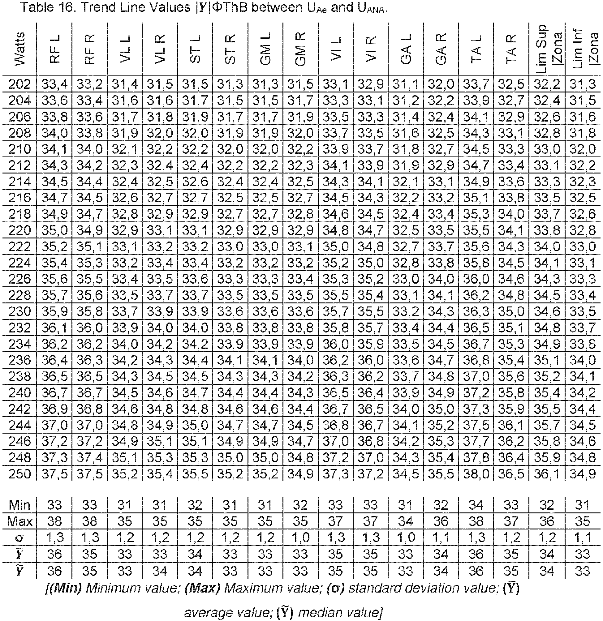


1.13. In Table 18, Table 19 and Table 20, the calculated values of | Y |O2HHb of each TMM, at each intensity can be observed.


1.14. In Table 21, Table 22 and Table 23, the calculated values of | Y |ΦO2HHb of each TMM, at each intensity can be observed.


1.15. In Table 24, Table 25 and Table 26, the calculated values of | Y |HHb of each TMM, at each intensity can be observed.


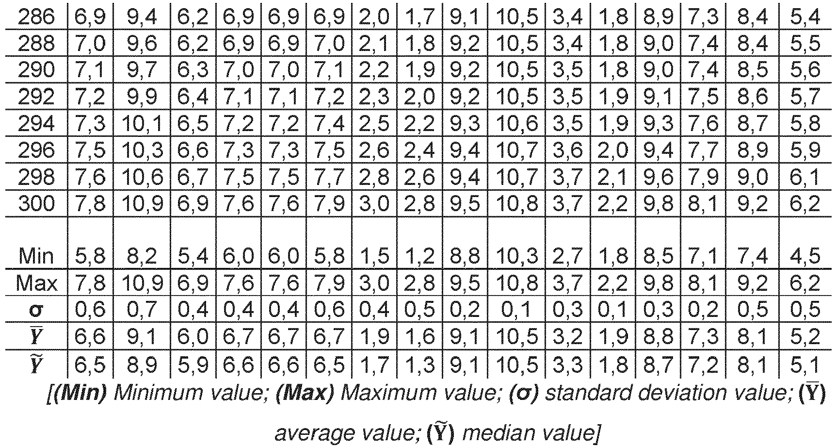
1.16. In Table 27, Table 28 and Table 29, the calculated values of | Y |ΦHHb of each TMM, at each intensity can be observed.


1.17. InFigure 52-100 , the graphical representation of the calculated values corresponding to the slope of the trend line( p ) of | Y |SmO2 %, | Y |O2HHb, | Y |ΦO2HHb, | Y |HHb, | Y |ΦHHb, | Y |ThB and | Y |ΦThB, of each TMM can be observed.
1.18. In Table 30, the intensity ranges which produce the 1st, 2nd and 3rd General Change in the Slopes of the Trend Lines of( p ) | Y |SmO2 %,( p ) | Y |O2HHb,( p ) | Y |ΦO2HHb,( p ) | Y |HHb,( p ) | Y |ThB and( p ) | Y |ΦThB, of each TMM can be observed.
The 1st General Change( p ) is equals the Minimum Activation Threshold (UAmin), the 2nd General Change( p ) is equals the Aerobic Threshold (UAe) and the 3rd General Change( p ) is equals the Threshold Anaerobic (UANA), of each TMM.Table 30. General changes in trend and physiological thresholds of each TMM. TMM 1st Change (p) 2nd Change (p) 3rd Change (p) UAmin Individual UAe Individual UAna Individual Rango| X | (Watts) Rango| X | (Watts) Rango| X | (Watts) | X | (Watts) | X | (Watts) | X | (Watts) RF L 134 - 138 198 - 206 246 - 266 136 202 256 RF R 132 - 142 198 - 208 244 - 266 137 203 255 VL L 130 - 138 192 - 206 254 - 270 134 199 262 VL R 130 - 140 196 - 206 254 - 268 135 201 261 ST L 132 - 144 196 - 206 254 - 268 138 201 261 ST R 130 - 138 192 - 204 254 - 276 134 198 265 GM L 132 - 138 192 - 208 244 - 262 135 200 253 GM R 130 - 140 194 - 206 238 - 262 135 200 250 VI L 132 - 150 190 - 206 244 - 270 141 198 257 VI R 126 - 140 184 - 206 250 - 258 133 195 254 GA L 126 - 138 194 - 214 258 - 274 132 204 266 GA R 126 - 138 190 - 212 256 - 260 132 201 258 TA L 130 - 138 192 - 206 252 - 258 134 199 255 TA R 132 - 144 194 - 210 246 - 270 138 202 258
1.19. In Table 31, the median values of all the general changes of( p ) of the set of TMS M, that are equivalent to UAmin, UAe and UANA of the global locomotor system can be observed.Table 31. General Change in Trend and Global Physiological Thresholds 1st General Change ( p ) 2nd General Change ( p ) 3rd General Change ( p ) UAmin UAe UAna Rango | X̃ | (Watts) 130 - 138 192 - 206 252 - 268 | X̃ | (Watts) 136 201 258 -
- In Table 9-11 and Table 18-23, the calculated value of | Y |SmO2 %, | Y |O2HHb and | Y |ΦO2HHb, of each TMM, in each INTTL greater than or equal to UAmin can be observed
- In Table 32-37, the results of the CSV of | Y |SmO2 %, | Y |ΦO2HHb and | Y |O2HHb, of each TMM and his TMCM, in each INTTL greater than or equal to UAmin can be observed.
- In Table 38, can be observed NSCSV equivalent to the value of CSV.
- In Table 39, Table 40 and Table 41, the values of Coef-( p ) of( p ) | Y |SmO2 %,( p ) | Y |O2HHb and( p ) | Y |ΦO2HHb, between each TMM and his TMCM can be observed.
- In Table 42, the equivalence of Coef-( p ) with the NS Coef-(p) of the general trend between each TMM and his TMCM can be observed.


Table 38. NSCSV equivalent to the values of CSV CSV Symmetry Level (NSCSV ) SmO2 % O2HHb - HHb ΦO2HHb - ΦHHb Perfect ≤ 0,01 ≤ 0,001 ≤ 0,01 Optimum > 0,01 ≤ 0,05 > 0,001 ≤ 0,005 > 0,01 ≤ 0,05 Minimal > 0,05 ≤ 0,20 > 0,005 ≤ 0,02 > 0,05 ≤ 0,2 Asymmetry > 0,20 > 0,02 > 0,2
- There is a Functional Factor Limitation due to Muscular Inhibition of Oxidative Capacity in the Left Rectus Femoris (RF L) because it meets the established criteria of Factor (A3) that can be determined: - 1) In Table 9 and Table 10, the minimum value of | Y |SmO2 % of RF L, is greater than 50% SmO2 %, in the 100% of INTTL greater than or equal to UAe and less than UAna, can be observed
- 2) in Table 34-37, the CSV of | Y |SmO2 %, | Y |O2HHb and | Y |ΦO2HHb of RF L with respect to RF R is asymmetric, in all INTTL greater than or equal to UAe and less than UAna can be observed.
- 3) In Table 39, Table 40 and Table 41, the general trend
( p ) | Y |SmO2 %,( p ) | Y |O2HHb and( p ) | Y |ΦO2HHb is symmetric in the >70% of the TMS M with respect their TMSCM, in the R-INTTL (UAmin- UAe) and (UAe - UAna) can be observed.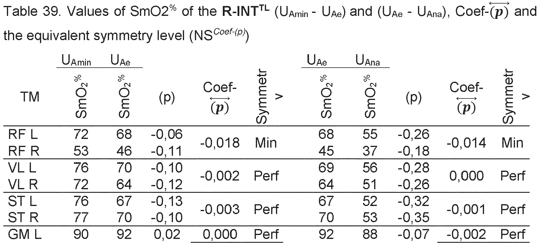
-
- In Table 9-29, the calculated value and minimum value | Y |SmO2 %, | Y |ΦO2HHb and | Y |O2HHb, of all TMS M, in each INTTL greater than or equal to UAmin can be observed
- In Table 32-37, the CSV between the value of | Y |SmO2 %, | Y |O2HHb and | Y |ΦO2HHb, of each TMM and his TMCM, in each INTTL greater than or equal to UAmin and less than UAna can be observed.
- In
Figure 52-100 ,( p ) calculated from | Y |SmO2 %,( p ) | Y |ΦO2HHb and( p ) | Y |O2HHb, of all TMS M, in each INTTL greater than or equal to UAe can be observed. - In Table 32-37, the values and NS Coef-(p) of
( p ) | Y |SmO2 %,( p ) | Y |ΦO2HHb and( p ) | Y |O2HHb, between each TMM and his TMCM, in the R-INTTL (UAmin - UAe) and (UAe - UAna) can be observed. - The TMS M (GM L, GM R, GA L and GA R) present a Limitation of the Neuromuscular Factor of Oxidative Capacity by meeting the criteria of Factor (A.4) that can be established:
- 1) In Table 9 and 10, the calculated values of | Y |SmO2 % of ( GM L, GM R, GA L and GA R) are ≥65% SmO2 %, in each INTTL greater than or equal to UAmin and less than UAna can be observed.
- 2) In Table 32-37, the general trend of
( p ) | Y |SmO2 %,( p ) | Y |ΦO2HHb and( p ) | Y |O2HHb, of each TMM and his TMCM is symmetrically optimal, in more than 70% of TMS M and their TMSCM, in the R-INTTL (UAmin- UAe) and (UAe - UAna) can be observed. - 3) In Table 9-11 and Table 18-23, the calculated values of | Y |SmO2 %, | Y |ΦO2HHb and | Y |O2HHb of ( GM L , GM R, GA L and GA R) are greater than the values of | Y |SmO2 %, | Y |ΦO2HHb and | Y |O2HHb, of the other TMSM, in all INTTL greater than or equal to UAmin can be observed.
- 4) In Table 9-11, the calculated values of | Y |SmO2 % of the TMS M, in more than 60% of the TMS M ( RF L, RF R, VL R, ST L, ST R, VI L, VI R, TA L, TA R ), present values ≤45% SmO2 %, in at least one INTTL greater than or equal to UAe can be observed.
-
- In Table 9-11 and Table 18-23, the calculated values of | Y |SmO2 %, | Y |O2HHb and | Y |ΦO2HHb of each TMM, in each INTTL greater than or equal to UAmin can be observed.
- In Table 9-11 and Table 18-23, the calculated values of SmO2 %, O2HHb and ΦO2HHb, of the Upper Limit of the Optimal Zone |lim sup| ZonaOp ), in each INTTL greater than or equal to UAmin can be observed.
- In Table 9-11 and Table 18-23, the calculated values of SmO2 %, O2HHb and ΦO2HHb, of the Lower Limit of the Optimal Zone | lim inf | ZonaOp ), in each INTTL greater than or equal to UAmin can be observed.
- In Table 43, the type of Analytical Muscular Blood Flow Composition of each TMM, established from the criteria of Factor (B2.1) can be observed.
- In Table 43, the type of Hemoglobin Delivery Volume of each TMM, established from the criteria of Factor (B2.2) can be observed.
- In Table 43, the type of Blood Flow Delivery Rate of each TMM, established from the criteria of Factor (B2.3) can be observed.Table 43. Type of Performance of each TMM of factors (B2.1), (B2.2) and (B2.3), in each R-INTTL TM Rank intensity Flow Composition Delivery Volume Delivery rate RF L UAmin - UAe Optimal Optimal Optimal UAe - UAna >UAna RF R UAmin - UAe Lesser Lesser Lesser UAe - UAna >UAna VL L UAmin - UAe Optimal Optimal Optimal UAe - UAna >UAna VL R UAmin - UAe Optimal Optimal Optimal UAe - UAna >UAna ST L UAmin - UAe Optimal Optimal Optimal UAe - UAna >UAna ST R UAmin - UAe Optimal Optimal Optimal UAe - UAna >UAna GM L UAmin - UAe Excessive Lesser Lesser UAe - UAna >UAna GM R UAmin - UAe Excessive Lesser Lesser UAe - UAna >UAna VI L UAmin - UAe Lesser Lesser Lesser UAe - UAna >UAna VI R UAmin - UAe Lesser Lesser Lesser UAe - UAna Inefficient >UAna GA L UAmin - UAe Excessive Lesser Lesser UAe - UAna >UAna Higher GA R UAmin - UAe Excessive Lesser Lesser UAe - UAna >UAna TA L UAmin - UAe Lesser Lesser Lesser UAe - UAna >UAna TA R UAmin - UAe Lesser Lesser Lesser UAe - UAna >UAna Optimal Optimal Optimal -
- In Table 44-46, the maximum values of SmO2 %, O2HHb and ΦO2HHb of each MM, in each of the rest intervals (ID) performed can be observed.
- In Table 47, the highest level of symmetry (NSCSV) calculated between the combination of >70% of the maximum values of SmO2 %, O2HHb and ΦO2HHb, of each ID after a work interval (IT) of average INTTL greater than or equal to UAmin can be observed.


- In Table 47, the CSV values of the 100% of TMS M and 71 % of TMS M with higher NSCSV, in addition to the type of performance of Factor (B2.2) that the cardiovascular system performs in each IT can be observed.
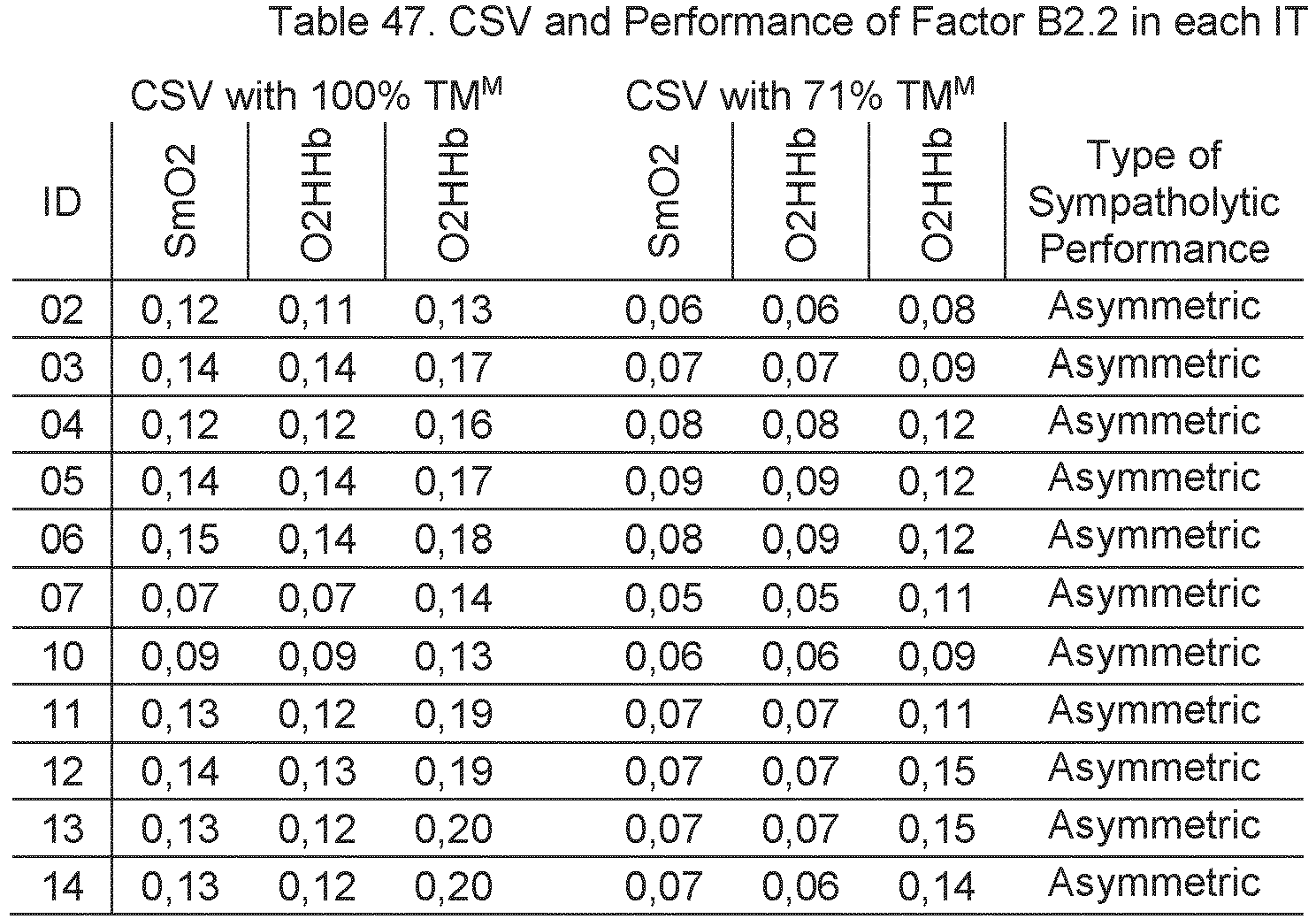
-
- In Table 44-46, the calculated maximum value of SmO2% in each ID, of each TMM can be observed.
- In Table 48, the difference calculated between the maximum values of SmO2 %, between the successive ID, of each TMM can be observed.
- In Table 48, the type of Evolution of Delivery of Oxygen-Loaded Blood established in each TMM analyzed, between each of the successive rest intervals based on the criteria established by Factor (B2.3) can be observed:

-
- In Table 49, the calculated values of | Y |ThB, in each of the Thresholds and in the maximum intensity recorded, of each TMM can be observed.
- In Table 49, the values of( p ) | Y |ThB of each TMM, between in the R-INTTL (UAe - UAna) and (UAe - UAna-IntMax) can be observed.
- In Table 49 and Table 11, the minimum calculated values of SmO2 % of each TMM can be observed.
- In Table 49, the TMM that present a Limitation in the Performance Factor of the Muscle Pumping Factor for Venous Return by meeting the criteria of the Factor (B2.4) that can be observed: - ∘ The general trend of
( p ) | Y |ThB of TMM is[( p ) >0,0005] in one of the two R-INTTL (UAe - UAna) and/or (UAe - UAna - IntMax). - ∘ The values of SmO2 % of the TMM analyzed decrease to values <50% SmO2% during R-INTTL greater than or equal to UAe
-
- In Table 50, the calculated median values of de | Y |SmO2 %, | Ỹ |O2HHb, | Ỹ |ΦO2HHb, of each TMM, in each R-INTTL can be observed.
- In Table 9-11 and Table 18-23, the median calculated values of | Ỹ |SmO2 %, | Ỹ |O2HHb, | Ỹ |ΦO2HHb, of the Upper Limit of the Optimal Zone (| lim sup| ZonaOp )and the Lower Limit of the Optimal Zone (| lim inf | ZonaOp ) can be observed.
- In Table 50, the Type of Neuromuscular Activation Factor performed by each TMM, in each R-INTTL, based on the criteria established in Factor (B3.1) can be observed:


-
- In Table 51, the median values and standard deviation (σ) of ThB of ( RF R, VI R and TA L ), in each work interval (IT) can be observed.
- In Table 51, the minimum value of ThB of ( RF R, VI R and TA L ), in each of the rest intervals (ID), the average work intensity, the average pedalling cadence and the average HR of the previous IT can be observed.
- In Table 51, the calculation of the [( Median Value) - (σ) ], of each IT can be observed.
- There is a Limitation in the Neurovascular Structural Factor of the ( RF R, VI R and TA L ) during each of the work intervals, of average intensity greater than or equal to UAmin, followed by one ID, when complying the criteria established for Factor (B3.2) that can be observed

-
- In Table 52, the median values of SmO2 %, O2HHb, ΦO2HHb, HHb and ΦHHb of each TMM, in each muscle contraction frequency range (R-FCM), in the R-INTTL of 140-160w can be observed.
- In Table 52, the difference in the median value of SmO2 %, O2HHb, ΦO2HHb,HHb and ΦHHb of each TMM, of each R-FCM, with respect to the highest value of SmO2 %, O2HHb, ΦO2HHb,HHb and ΦHHb, of all R-FCM can be observed.
- In Table 52, the difference in the median value of HHb and ΦHHb of each TMM, of each R-FCM, with respect to the lowest value of HHb and ΦHHb, of all R-FCM can be observed.
- The following R-FCM are optimal because meeting the criteria established for Factor (B3.3) that can be established:
- o R- FCM Optimal: 79-80 Rpm
- o R-FCM Optimal: 81-82 Rpm


- The following muscle performance factors do not meet the criteria established by each factor to determine that any TMM or all of them develop at least one limitation of said factors:
- A 1. Structural Factor of Oxidative Capacity
- A2. Functional Factor of Oxidative Capacity by General Fatigue
- B1.1. Pulmonary Structural Factor
- B1.2. Pulmonary Functional Factor
- B2.1. Analytical Blood Flow Delivery Performance Factor)
6. Calculate all values of LinTrend | Y |SmO2 %, | Y |ThB, | Y |ΦThB, | Y |O2HHb, | Y |ΦO2HHb, | Y |HHb and | Y |ΦHHb, of each TMM, for each INTTL or R- INTTL.
7. Calculate the Slope (p) between each of the values of | Y |SmO2 %, | Y |ThB, | Y |ΦThB, | Y |O2HHb, | Y |ΦO2HHb, | Y |HHb and | Y |ΦHHb, from each TMM.
8. Calculate, analyze and determine all the trend changes of (p) in each of the LinTrend, of all the values | Y |SmO2 %, | Y |ThB, | Y |ΦThB, | Y |O2HHb, | Y |ΦO2HHb, | Y |HHb and | Y |ΦHHb, of each TMM.
9. Calculate, analyze and establish between which two values of INTTL or R- INTTL occurs the 1st, 2nd and 3rd General Change of the trend of the slope (p) of LinTrend | Y |SmO2 %, | Y |ThB, | Y |ΦThB, | Y |O2HHb, | Y |ΦO2HHb, | Y |HHb and | Y |ΦHHb, in each TMM.
10. Establish the intensity range in which the 1st General Change of the slope ( p ) trend occurs, of each TMM, through the combining at least 4 of the 7 INTTL or R- INTTL , analyzed and established in the previous step (9), for each TMM.
11. Establish the intensity range in which the 2nd General Change of the slope ( p ) trend occurs, of each TMM, through the combining at least 4 of the 7 INTTL or R- INTTL , analyzed and established in the previous step (9), for each TMM.
12. Establish the intensity range in which the 3rd General Change of the slope ( p ) trend occurs, of each TMM, through the combining at least 4 of the 7 INTTL or R- INTTL , analyzed and established in the previous step (9), for each TMM.
13. Establish the Physiological Thresholds of each TMM from the data calculated and established in the previous points:
| 1st General Change (p) | 2nd General Change (p) | 3rd General Change (p) | |
| UAmin Individual | UAe Individual | UAna Individual | |
| Rank| X | (Watts) | Rank| X | (Watts) | Rank| X | (Watts) | |
| TMM | | X | (Watts) | | X | (Watts) | | X | (Watts) |
14. Establish the central INTTL or R- INTTL of the General Physiological Thresholds from the median of the values of the individual thresholds of all TMs m:
| 1st General Change (p) | 2nd General Change (p) | 3rd General Change (p) | |
| UAmin | UAe | UAna | |
| Rank| X | (Watts) | Rank| X | (Watts) | Rank| X | (Watts) | |
| TMM | | X | (Watts) | | X | (Watts) | | X | (Watts) |
15. Coming up next, the processing system can then also determine the level of symmetry or asymmetry that has been obtained between at least two groups of values and/or trend of the values | Y |SmO2 %, | Y |ThB, | Y |ΦThB, | Y |O2HHb, | Y |ΦO2HHb, | Y |HHb and/or | Y |ΦHHb, between two INTTL or two R- INTTL , between at least two TMs m:


| Symmetry Level (NS Coef-(p) ) | Coef- | |||||
| SmO2 % | O2HHb - HHb | ΦO2HHb- ΦHHb | ||||
| Perfect | ≤ 0,01 | ≤ 0,001 | ≤ 0,01 | |||
| Optimum | > 0,01 | ≤ 0,05 | > 0,001 | ≤ 0,005 | > 0,01 | ≤ 0,05 |
| Minimal | > 0,05 | ≤ 0,15 | > 0,005 | ≤ 0,015 | > 0,05 | ≤ 0,15 |
| Asymmetry | > 0,15 | > 0,015 | > 0,15 | |||


| UAe | UAna | Int Work | Rank | Min | Factor B2.4 | ||
| UAe - UAna | >UAna | | Ỹ |SmO2 % | |||||
| RF L | 12,81 | 12,76 | 12,77 | -0,0009 | 0,0003 | 40 | |
| RF R | 12,72 | 12,77 | 12,94 | 0,0008* | 0,0035* | 20 | Limitation in >UAe |
| VL L | 12,01 | 12,01 | 12,04 | 0,0000 | 0,0007* | 46 | Limitation in >UAna |
| VL R | 12,07 | 12,04 | 12,15 | -0,0007 | 0,0022* | 38 | Limitation in >UAna |
| ST L | 12,10 | 12,06 | 12,23 | -0,0008 | 0,0035* | 33 | Limitation in >UAna |
| ST R | 11,96 | 12,03 | 12,11 | 0,0014* | 0,0017* | 38 | Limitation in >UAe |
| GM L | 12,14 | 11,85 | 11,70 | -0,0057 | -0,0031 | 79 | |
| GM R | 12,13 | 11,85 | 11,75 | -0,0057 | -0,0020 | 84 | |
| VI L | 12,66 | 12,72 | 12,75 | 0,0011* | 0,0006* | 28 | Limitation in >UAe |
| VI R | 12,60 | 12,67 | 12,70 | 0,0015* | 0,0006* | 16 | Limitation in >UAe |
| GA L | 11,93 | 11,71 | 11,55 | -0,0044 | -0,0033 | 55 | |
| GA R | 12,27 | 12,08 | 11,67 | -0,0040 | -0,0082 | 79 | |
| TA L | 12,91 | 12,95 | 12,98 | 0,0008* | 0,0006* | 26 | Limitation in >UAe |
| TA R | 12,43 | 12,47 | 12,53 | 0,0009* | 0,0012* | 38 | Limitation in >UAe |

Claims (17)
- Monitoring and evaluation method of the physical performance of a subject that includes the stages of:a. providing two or more Near-Infrared Spectroscopy sensors (NIRS), a cardiac monitoring device and a locomotor work intensity device or monitor;b. placing or adhering the NIRS sensors on the muscle tissues (TM) to be evaluated, place the heart rate device on the subject's chest, place the activity monitoring device and the locomotive intensity meter;c. starting data recording of all the devices and activity monitors, minimally from the start of the locomotive activity evaluated and sending it to a data processing system;d. recording, through the data processing system, the data captured, during the development of at least one Cyclical Locomotive-Physical Activity (AFC), where:- the Monitored Cyclical Physical Activity (AFCM) is continuous or interval,- the activity monitor records the entire time scale from the beginning to the end of the AFCM, including the multiple intervals of work and/or rest if performed,- the recording frequency of the data for each device is less than 6 seconds,- the AFCM is stable, incremental, decreasing, variable locomotor intensity or a combination of the above,- the AFCM includes a period of previous warm-up,- if the AFCM does not include at least one Rest interval (ID), the data recording will end 1 minute after the AFC ceases and that minute will be counted as an ID,- the Locomotor Work Intensity (INTTL) or the average Locomotor Work Intensity Range (R-INTTL) is greater than or equal to the Minimum Activation Threshold (UAmin);e. obtaining at least the following monitored data from all devices with their respective temporary registration:- Muscular Oxygen Saturation (SmO2% - %) and Absolute Capillary Hemoglobin (ThB - g/dL) of each of the monitored muscle tissues (TMM) that participate in AFCM, through NIRS devices,- Heart rate (HR - bpm), through the heart rate monitor,- Power (Watts), Running Speed (Km/h), through the locomotive intensity meter or monitor,- time record or timescale of the AFCM, with all the time records of the start or end of AFCM, and the start and end of the different intervals developed during the AFCM, through the locomotive activity monitor,- cadence (rpm) or acceleration, through external locomotor performance devices and/or monitors,- analysis of metabolic gases (VO2/CO2), lactate measurements, and data from thermographic cameras, using physiological locomotor performance devices and/or monitors;f. synchronizing, linking and joining the data obtained in a single time scale of joint data from the time record scale collected by the activity monitor during the AFCM and the time record of each device, through the data processing system;g. calculating, through the data processing system, at least the following values for each Monitored Muscle Tissue (TMM) that participates in the AFCM from the recorded data of SmO2 % and ThB of:Oxygen-Charged Capillary Hemoglobin - g/dL (O2HHb), through the formula:
% (SmO2) * g/dL (ThB) = g/dL (O2HHb)
Oxygen Discharged Capillary Hemoglobin - g/dL (HHb), through the formula:
g/dL (ThB) - g/dL (O2HHb) = g/dL (HHb)
Muscle Blood Flow of Muscle Hemoglobin - g/dL/s (ΦThB), through the formula:
[g/dL (ThB) * (HR)] / 60 = g/dL/seg (ΦThB)
Muscular Blood Flow of Oxygen Charged Hemoglobin - g/dL/s (ΦO2HHb), through the formula:
[g/dL (O2HHb) * (HR)] / 60 = g/dL/seg (ΦO2HHb)
Muscular Blood Flow of Oxygen Discharged Hemoglobin - g/dL/s (ΦHHb), through the formula
[g/dL (HHb) * (HR)] / 60 = g/dL/seg (ΦHHb)
h. filtering and excluding, through the data processing system, the data obtained erroneously and/or due to registration error by devices during AFCM;i. filtering and excluding, through the processing system, the values that are not within the following ranges, as well as the data obtained from the calculation of any of them:- SMO2% [Between 1% SmO2 and 99% SmO2]- ThB [Between 9.5 g/dL and 14,9 g/dL]- HR [Between 40ppm and 230ppm];j. filtering and excluding, through the processing system, the values that present a difference greater than that established in the following parameters between the temporary records of the analyzed value with respect to the previous value and the temporally subsequent value, as well as all the data obtained from the calculation of any of them:- Difference of SmO2% [> ±10% SmO2%]- Difference of ThB [> ±0.3 g/dL]- Difference of HR [> ±7ppm]. - Evaluation and monitoring method according to claim 1, which further comprises the steps of:k. filtering and excluding all values obtained, calculated and/or recorded during all ID or without AFC,I. filtering and excluding all values obtained, calculated and/or recorded during the first minute of each work interval (IT),m. filtering and excluding all values obtained, calculated and/or registered when the value of the INTTL or R-INTTL in the same temporary register is equivalent to "0",n. filtering and excluding all the values obtained, calculated and/or registered when the value of Muscle Contraction Frequency (FCM) or Muscle Contraction Frequency Range (R-FCM) in the same time register is equivalent to "0",o. selecting and performing one of the following procedures:- a first procedure comprising the steps of:o calculating the statistical median value (
 o calculating and establishing the Trend Line (LinTrend) of the median values (


 - a second procedure comprising the steps of:o calculating the statistical average value (Y̅) of the values of SmO2 %, ThB, ΦThB, O2HHb, ΦO2HHb, HHb, ΦHHb, of each TMM, during AFCM, in each INTTL or R- INTTL, registered during the AFCM;o calculating and establishing the LinTrend of the average values (Y̅-INTTL) or (Y̅-R-INTTL) obtained from Y̅SmO2 %, Y̅ThB, Y̅ΦThB, Y̅O2HHb, Y̅ΦO2HHb, Y̅HHb and Y̅ΦHHb, in each TMM;- a third procedure comprising a step of:o calculating and establishing the LinTrend (Value/INTTL) or (Value/R-INTTL), from all filtered values of SmO2%, ThB, ΦThB, O2HHb, ΦO2HHb, HHb, ΦHHb, in each TMM;p. calculating all values of LinTrend |Y|SmO2 %, |Y|ThB, |Y|ΦThB, |Y|O2HHb, |Y|ΦO2HHb, |Y|HHb and |Y|ΦHHb, of each TMM, for each INTTL or R- INTTL;q. calculating the Slope (p) between each of the values of |Y|SmO2 %, |Y|ThB, |Y|ΦThB, |Y|O2HHb, |Y|ΦO2HHb, |Y|HHb and |Y|ΦHHb, from each TMM;r. calculating, analyzing and determining all the trend changes of (p) in each of the LinTrend, of all the values |Y|SmO2 %, |Y|ThB, |Y|ΦThB, |Y|O2HHb, |Y|ΦO2HHb, |Y|HHb and |Y|ΦHHb, of each TMM;s. calculating, analyzing and establishing between which two values of INTTL or R-INTTL occurs the 1st, 2nd and 3rd Change in each TMM of the trend of the slope (p) of each LinTrend, through the combining at least 4 of the 7 possible (p) changes of |Y|SmO2 %, |Y|ThB, |Y|ΦThB, |Y|O2HHb, |Y|ΦO2HHb, |Y|HHb and |Y|ΦHHb;t. establishing the Physiological Thresholds of each TMM equivalent to the trend changes:
1st Change (p) 2nd Change (p) 3rd Change (p) UAmin Individual UAe Individual UAna Individual Rank|X| (Watts) Rank|X| (Watts) Rank|X| (Watts) TMM |X| (Watts) |X| (Watts) |X| (Watts) u. establishing the INTTL or R- INTTL of the General Physiological Thresholds from the median of the values of the individual thresholds of all TMs M:1st General 2nd General 3rd General Change (p) Change (p) Change (p) TMM UAmin UAe UAna Rank|X| (Watts) Rank|X| (Watts) Rank|X| (Watts) |X| (Watts) |X| (Watts) |X| (Watts) - Monitoring and evaluation method according to claim 2, further comprising the steps of:- calculating, analyzing and determining the CSV, between at least two sets of values |Y|SmO2 %, |Y|ThB, |Y|ΦThB, |Y|O2HHb, |Y|ΦO2HHb, |Y|HHb or |Y|ΦHHb, established between two determined INTTL or R- INTTL, between at least two determined TMs M:
 - establishing the Symmetry Level (NSCSV) from the CSV value calculated from the values |Y|SmO2 %, |Y|ThB, |Y|ΦThB, |Y|O2HHb, |Y|ΦO2HHb, |Y|HHb or |Y|ΦHHb, between two INTTL or two R- INTTL determined, between at least two TMs M determined:- establishing the Symmetry Level (NSCSV) from the CSV value, where:
Symmetry Level (NSCSV ) CSV SmO2 % O2HHb - HHb ΦO2HHb - ΦHHb Perfect ≤ 0,01 ≤ 0,001 ≤ 0,01 Optimum > 0,01 ≤ 0,05 > 0,001 ≤ 0,005 > 0,01 ≤ 0,05 Minimal > 0,05 ≤ 0,20 > 0,005 ≤ 0,02 > 0,05 ≤ 0,2 Asymmetry > 0,20 > 0,02 > 0,2 - calculating, analyzing and determining the slope-trend(p) |Y| of at least |Y|SmO2 %, |Y|O2HHb, |Y|ΦO2HHb, |Y|HHb and/or |Y|ΦHHb, between two INTTL or two R-INTTL, of at least two TMs M:
(p) is the slope-trend; |Y|1 the determined value of SmO2%, O2HHb, ΦO2HHb, HHb o ΦHHb, of the first LNTTL or R-INTTL and |Y|2 of the second INTTL or R-INTTL; |X| 1 is the first LNTTL or R-INT TL and |X| 2 the second INTTL or R-INTTL;- calculating, analyzing and establishing the Coef-(p) of(p) |Y|SmO2,(p) |Y|O2HHb,(p) |Y|ΦO2HHb,(p) |Y|HHb and/or(p) |Y|ΦHHb between two INTTL or two R-INTTL, of one TMM determined with respect to the trend of(p) |Y|smO2 %,(p) |Y|O2HHb,(p) |Y|ΦO2HHb,(p) |Y|HHb and/or(p) |Y|ΦHHb of another TMM or a set of values trends of(p) |Y|SmO2 %,(p) |Y|O2HHb,(p) |Y|ΦO2HHb,(p) |Y|HHb and/or(p) |Y|ΦHHb of two or more TMs M:

(p 1) |Y| is the slope-trend of the analyzed TMM;- establishing the Symmetry Level (NS Coef-(p) ) from the calculated value of Coef-(p)(p) |Y|SmO2,(p) |Y|O2HHb,(p) |Y|ΦO2HHb,(p) |Y|HHb ∘(p) |Y|ΦHHb of the analyzed TMM:Symmetry Level (NS Coef-(p)) Coef- (p) SmO2 % O2HHb - HHb ΦO2HHb- ΦHHb Perfect ≤ 0,01 ≤ 0,001 ≤ 0,01 Optimum > 0,01 ≤ 0,05 > 0,001 ≤ 0,005 > 0,01 ≤ 0,05 Minimal > 0,05 ≤ 0,15 > 0,005 ≤ 0,015 > 0,05 ≤ 0,15 Asymmetry > 0,15 > 0,015 > 0,15 - Monitoring and evaluation method according to claims 2 and 3, further comprising the steps of:- evaluating the value of |Y|SmO2 % in each INTTL or R-INTTL, INTTL greater than or equal to UAmin and less than or equal to UAna;- calculating, comparing, evaluating and establishing the Coefficient of Symmetry between Values (CSV) and the Level of Symmetry (NSCSV) between |Y|SmO2 %, |Y|O2HHb and |Y|ΦO2HHb of each TMM and his Contralateral Muscle Tissue Monitored (TMCM), in each INTTL or R-INTTL INTTL greater than or equal to UAmin and less than or equal to UAna;- calculating, comparing and evaluating the General Trend of the Values (TGV [
(p) ]) |Y|SmO2 %, |Y|ΦO2HHb and |Y|O2HHb, of all TMS M, in the R-INTTL (UAmin-UAe) and (UAe - UAna),- calculating, comparing and establishing the lowest value of Coef-(p) and the equivalent NS Coef-(p) of(p) |Y|SmO2 %,(p) |Y|ΦO2HHb and(p) |Y|O2HHb, between the combination of at least 70-75% of the TMS M, in the R-INTTL (UAmin - UAe) and (UAe - UAna);- determining that the following criteria are met to establish a limitation in Factor (A1):1) the value of |Y|SmO2 % in each INTTL or R-INTTL INTTL greater or equal than UAmin and less than or equal to UAna, is ≥70% SmO2%, in at least 70-75% of TMS M;2) the values of |Y|SmO2 %, |Y|O2HHb and |Y|ΦO2HHb of each TMM and TMCM, have at least one optimal symmetry, in each INTTL or R-INTTL greater than or equal to UAmin and less than or equal to UAna, in at least the 70-75% of TMS M;3) the TGV of de(p) |Y|SmO2 %,(p) |Y|ΦO2HHb and(p) |Y|O2HHb is symmetric between the combination of at least 70-75% of TMS M, in the R-INTTL (UAmin-UAe) and (UAe - UAna);4) the TGV of de(p) |Y|SmO2 %,(p) |Y|ΦO2HHb and(p) |Y|O2HHb is symmetric between each TMM and his TMCM, in at least 80-85% of TMS M, in the R-INTTL (UAmin - UAe) and (UAe - UAna). - Monitoring and evaluation method according to any of claims 2 to 4, wherein in addition to comprising steps f) to u), also comprise the steps of:- evaluating the values of |Y|SmO2 %, |Y|O2HHb and |Y|ΦO2HHb of each TMM, in each INTTL or R-INTTL greater than or equal to UAmin,- calculating and evaluating the difference of SmO2% between the value of |Y|SmO2 % of each TMM and his TMCM, in each INTTL or R-INTTL greater than or equal to UAmin;- comparing, evaluating and determining the CSV and NSCSV between the values of |Y|SmO2 %, |Y|ΦO2HHb and |Y|O2HHb of each TMM and his TMCM, in each INTTL or R-INTTL greater than or equal to UAmin;- calculating, comparing and evaluating the TGV [
(p) of |Y|SmO2 %, |Y|ΦO2HHb and |Y|O2HHb of all TMS M, in the R-INTTL (UAmin- UAe) and (UAe - UAna);- calculating, comparing and establishing the lowest value of Coef-(p) and the equivalent NS Coef-(p) of(p) |Y|SmO2 %,(p) |Y|ΦO2HHb and(p) |Y|O2HHb, between the combination of at least 50-55% of the TMS M, in the R-INTTL (UAmin - UAe) and (UAe - UAna);- determining that the following criteria are met to establish a limitation in Factor (A2):1) the difference between the value of |Y|SmO2 % of each TMM and his TMCM is >5% SmO2%, in the 95% of INTTL or R-INTTL greater than or equal to UAmin, in at least the 70-75% of TMS M;2) the value of |Y|SmO2 % is ≥55% SmO2%, in the 80% of TMS M, in each INTTL or R-INTTL greater than or equal to UAmin and less than or equal to UAna;3) the values of |Y|SmO2 %, |Y|O2HHb and |Y|ΦO2HHb are asymmetric in at least the 50% of INTTL or R-INTTL greater than or equal to UAmin, between one TMM and his TMCM, in at least the 70 -75% of TMS M;4) the TGV of de(p) |Y|SmO2 %,(p) |Y|ΦO2HHb and(p) |Y|O2HHb is asymmetric between the combination of at least the 50-55% of TMS M, in the R-INTTL (UAmin - UAe) and (UAe - UAna). - Monitoring and evaluation method according to any of claims 2 to 5, further comprising the steps of:- evaluating the value of |Y|SmO2 % of at least one TMM, in each INTTL or R-INTTL greater than or equal to UAmin,- calculate, comparing and evaluating the value of |Y|SmO2 %, |Y|O2HHb and |Y|ΦO2HHb of at least one TMM with the values of his TMCM, in each INTTL or R-INTTL greater than or equal to UAmin;- calculating, evaluating and determining the value of CSV and NSCSV of |Y|SmO2 %, |Y|ΦO2HHb and |Y|O2HHb, of at least one TMM and his TMCM, in each INTTL or R-INTTL greater than or equal to UAmin,- calculating, comparing and evaluating the TGV [
(p) ] of |Y|SmO2 %, |Y|ΦO2HHb and |Y|O2HHb of all TMS M, in the R-INTTL (UAmin- UAe) and (UAe - UAna);- calculating, evaluating and determining the lowest value of Coef-(p) and the equivalent NS Coef-(p) between the values of(p) |Y|SmO2 %,(p) |Y|ΦO2HHb and(p) |Y|O2HHb, of at least the combination of the 50-55% TMS M;- determining that the following criteria are met to establish a limitation on Factor (A3):1) the value of |Y|SmO2 % is ≥50% SmO2% in the TMM analyzed, in the 95% of INTTL or R-INTTL greater than or equal to UAmin,2) the values of |Y|SmO2 %, |Y|O2HHb |Y|y ΦO2HHb of the TMM analyzed are greater than the values of his TMCM, in the 95% of INTTL or R-INTTL greater than or equal to UAmin,3) the TGV of(p) |Y|SmO2 %,(p) |Y|ΦO2HHb and(p) |Y|O2HHb is asymmetric between the TMM analyzed and his TMCM, in the R-INTTL (UAmin- UAe) and (UAe - UAna);4) the TGV of(p) |Y|SmO2 %,(p) |Y|ΦO2HHb and(p) |Y|O2HHb is symmetric between the combination of at least the 50-55% of TMS M, in the R-INTTL (UAmin - UAe) and (UAe - UAna). - Monitoring and evaluation method according to any of claims 2 to 6, further comprising the steps of:- evaluating the value of |Y|SmO2 %, |Y|ΦO2HHb and |Y|O2HHb, of each TMM, in each INTTL or R-INTTL greater than or equal to UAmin,- calculating, evaluating and determining the value of CSV and the equivalent NSCSV of de |Y|SmO2 %, |Y|ΦO2HHb and |Y|O2HHb, of at least one TMM and his TMCM, in each INTTL or R-INTTL greater than or equal to UAmin,- calculating, comparing and evaluating the TGV [
(p) ]) of |Y|SmO2 %, |Y|ΦO2HHb and |Y|O2HHb of all TMS M, in the R-INTTL (UAmin- UAe) and (UAe - UAna);- calculating, evaluating and determining Coef-(p) and the equivalent NSCoef-(p) between the values(p) |Y|SmO2 %,(p) |Y|ΦO2HHb and(p) |Y|O2HHb, of each TMM and his TMCM, in the R-INTTL (UAmin- UAe) and (UAe - UAna);- determining that the following criteria are met to establish a limitation on Factor (A4):1) the value of |Y|SmO2 % of the TMM analyzed and of his TMCM is greater than or equal to 65% SmO2 %, in each INTTL or R-INTTL greater than or equal to UAmin;2) the trend of(p) |Y|SmO2 %,(p) |Y|ΦO2HHb and(p) |Y|O2HHb,in the 70% of TMS M and their TMSCM are minimally symmetric, in the R-INTTL (UAmin - UAe) and (UAe - UAna);3) the values of |Y|SmO2 %, |Y|ΦO2HHb and |Y|O2HHb of the TMM analyzed and his TMCM are greater than the values of at least the 70-75% of the remaining TMS M, in each INTTL or R-INTTL greater than or equal to UAmin,4) the values of |Y|SmO2 % of at least the 50-55% of TMs M is ≤45% SmO2%, in any INTTL or R-INTTL greater than or equal to UAe. - Monitoring and evaluation method according to any of the preceding claims, where in addition to the TMs M to be evaluated, one or more TMs M that participate in the breathing process are evaluated, and where they also comprise the steps of:- calculating, analyzing and evaluating the value of |Y|SmO2 % of at least one TMM involved in the breathing process [inspiration (inhalation) and expiration (exhalation)] during AFCM, in each INTTL or R-INTTL greater than or equal to UAmin,- calculating, analyzing and evaluating the trend
(p) of the SmO2 % and ΦO2HHb values of all TMS M, on the initial 5 and 10 seconds of at least one ID after an IT of INTTL or R-INTTL average greater than or equal to UAe;- determining that the following criteria are met to establish a limitation on Factor (B1.1):1) the trend of the values(p) |Y|SmO2 % and(p) |Y|ΦO2HHb in the initial 5 seconds, in all ID after an IT of INTTL or R-INTTL average greater than or equal to UAe, is less than [(p) < 0000,5], in at least 70% of TMS M;2) the trend of the values(p) SmO2 % and(p) ΦO2HHb in the initial 10 seconds, in all ID after an IT of INTTL or R-INTTL average greater than or equal to UANA, is less than [(p) < 0000,5], in at least 70% of TMS M;3) the value of |Y|SmO2 % is >50% SmO2% in the TMs M that participate in the breathing process [inspiration (inhalation) and expiration (exhalation)], in at least one INTTL or R-INTTL greater than or equal to UAmin. - Monitoring and evaluation method according to any of the preceding claims, where in addition to the TMs M to be evaluated, one or more TMs M that participate in the breathing process are evaluated, and where they also comprise the steps of:- calculating, analyzing and evaluating the value of |Y|SmO2 % of at least one TM involved in the breathing process [inspiration (inhalation) and expiration (exhalation)] during AFCM, in each INTTL or R-INTTL greater than or equal to UAmin,- calculating, analyzing and evaluating the trend
(p) of the SmO2 % and ΦO2HHb values of all TMS M, in the initial 5 seconds, of at least one ID after an IT of INTTL or R-INTTL average greater than or equal to UAe;- determining that the following criteria are met to establish a limitation on Factor (B1.1):1) the trend of the values(p) SmO2 % and(p) ΦO2HHb in the initial 5 seconds, in all ID after an IT of INTTL or R-INTTL average greater than or equal to UAe, is less than [(p) < 0000,5], in at least 70% of TMS M;2) the value of |Y|SmO2 % is ≤50% SmO2 % in the TMS M that participate in the breathing process [inspiration (inhalation) and expiration (exhalation)], in at least one INTTL or R-INTTL greater than or equal to UAmin. - Monitoring and evaluation method according to any of claims 2 to 9, further comprising the steps of:- calculating the value of |Y|SmO2 %, |Y|O2HHb, |Y|ΦO2HHb, of each TMM, in at least one INTTL or R-INTTL greater than or equal to UAmin.- calculating the values of SmO2 %, O2HHb and ΦO2HHb of the Upper Limit of the Optimal Zone (|lim sup| ZonaOp) and the Lower Limit of the Optimal Zone |lim inf| ZonaOp, in the determined INTTL or R-INTTL, from the following calculation:

 - comparing and evaluating the values of |Y|SmO2 %, |Y|O2HHb and |Y|ΦO2HHb, of at least one TMM with the values of SmO2%, O2HHb and ΦO2HHb of |lim inf| ZonaOp and of |lim sup| ZonaOp, in analyzed INTTL or R-INTTL greater than or equal to UAmin,- determining the type of performance of the Factor (B.2.1.1) that develops at least one TMM analyzed, in the analyzed INTTL or R-INTTL, based on the following criteria:o excessive Muscle Oxygen Amount if:▪ the value of |Y|SmO2 % of the TMM is ≤80% SmO2 % in the analyzed INTTL or R-INTTL;▪ the value of |Y|SmO2 % of the analyzed TMM is greater than SmO2 %|lim sup| ZonaOp, in the analyzed INTTL or R-INTTL;▪ the difference between the value of |Y|SmO2 % of the analyzed TMM and SmO2 % |lim sup| ZonaOp is ≥15% SmO2%, in the analyzed INTTL or R-INTTL;o greater Amount of Muscular Oxygen if:▪ the value of |Y|SmO2 % of the analyzed TMM is greater than SmO2 %|lim sup| ZonaOp, in the analyzed INTTL or R-INTTL;▪ the difference between the value of |Y|SmO2 % of the analyzed TMM and SmO2 %|lim sup| ZonaOp, is <15% SmO2%, in the analyzed INTTL or R-INTTL;∘ optimal Amount of Muscular Oxygen if:▪ the value of |Y|SmO2 % of the analyzed TMM is equal or less than SmO2 %|lim sup| ZonaOp, in the analyzed INTTL or R-INTTL;▪ the value of |Y|SmO2 % of the analyzed TMM is equal or greater than SmO2 % |lim inf| ZonaOp, in the analyzed INTTL or R-INTTL;o lower Amount of Muscular Oxygen if:▪ the value of |Y|SmO2 % of the analyzed TMM is greater than SmO2 %|lim inf| ZonaOp, in the analyzed INTTL or R-INTTL;▪ the value of |Y|SmO2 % of the analyzed TMM is >20% SmO2%, in the analyzed INTTL or R-INTTL;o inefficient or Low Amount of Muscular Oxygen if:▪ the value of |Y|SmO2 % of the analyzed TMM is greater than SmO2 %|lim inf| ZonaOp, in the analyzed INTTL or R-INTTL;▪ the value of |Y|SmO2 % of the analyzed TMM is <20% SmO2%, in the analyzed INTTL or R-INTTL;- determining the type of performance of the Factor (B.2.1.2) that develops at least one analyzed TMM, in the analyzed INTTL or R-INTTL, based on the following criteria:o higher Hemoglobin Delivery Volume if:▪ the value of |Y|O2HHb of the analyzed TMM is greater than O2HHb |lim sup| ZonaOp, in the INTTL or R-INTTL analyzed;∘ optimal Hemoglobin Delivery Volume if:▪ the value of |Y|O2HHb of the analyzed TMM analyzed is equal or less than O2HHb |lim sup| ZonaOp, in the analyzed INTTL or R-INTTL;▪ the value of |Y|O2HHb of the analyzed TMM is equal or greater than O2HHb |lim inf| ZonaOp, in the analyzed INTTL or R-INTTL;∘ lower Hemoglobin Delivery Volume if:▪ the value of |Y|O2HHb of the analyzed TMM a is less than O2HHb |lim inf| ZonaOp, in the analyzed INTTL or R-INTTL;- determining the type of performance of the Factor (B.2.1.3) that develops at least one analyzed TMM, in the analyzed INTTL or R-INTTL, based on the following criteria:o higher Blood Flow Delivery Rate if:▪ the value of |Y|ΦO2HHb of the analyzed TMM is greater than the value of ΦO2HHb|lim sup| ZonaOp, in the analyzed INTTL or R-INTTL;∘ optimal Blood Flow Delivery Rate if:▪ the value of |Y|ΦO2HHb of the analyzed TMM is equal or less than of ΦO2HHb|lim sup| ZonaOp, in the analyzed INTTL or R-INTTL;▪ the value of |Y|ΦO2HHb of the analyzed TMM is equal or greater than ΦO2HHb |lim inf| ZonaOp, in the analyzed INTTL or R-INTTL;o lower Blood Flow Delivery Rate if:▪ the value of |Y|ΦO2HHb of the analyzed TMM is less than ΦO2HHb |lim inf| ZonaOp, in the analyzed INTTL or R-INTTL.
 - Monitoring and evaluation method according to any of claims 2 to 10, further comprising the steps of:- calculating, comparing and evaluating the maximum value of SmO2 %, O2HHb and ΦO2HHb of all TMS M, in at least one ID;- calculating, evaluating and determining the value of CSV and the equivalent NSCSV of the maximum value of SmO2 %, ΦO2HHb and OzHHb, of all TMS M, in at least one ID;- calculating, evaluating and determining the lowest value of CSV and the equivalent NSCSV of the maximum value of SmO2 %, ΦO2HHb and O2HHb, from the combination of at least the 70-75% of the TMS M, in at least one ID;- determining the type of performance of the Factor (B.2.2), just at the moment of cessation of locomotor work, based on the following criteria:∘ perfect performance if:▪ the maximum values of SmO2 %, O2HHb and ΦO2HHb are symmetrically perfect, between all TMS M, in the analyzed ID;∘ optimal performance if:▪ the maximum values of SmO2 %, O2HHb and ΦO2HHb, are symmetrically optimal, between the combination of at least the 70-75% of the TMS M, in the analyzed ID;o asymmetric Performance if:▪ the maximum values of SmO2 %, O2HHb and ΦO2HHb, are not symmetrically optimal, between the combination of at least the 70-75% of the TMS M, in the analyzed ID.
- Monitoring and evaluation method according to any of claims 2 to 11, further comprising the steps of:- calculating, comparing and evaluating the maximum value of SmO2% between two ID, separated by at least one IT of at least one TMM;- determining the type of performance of the Factor (B.2.3) that develops, at least one analyzed TMM, between two ID, separated by a IT, based on the following criteria:o Significant increase:▪ increase >5% SmO2%, in the maximum value of SmO2%, of the analyzed TMM, in the 2nd ID in compared to the 1ST LD;o Slight Increase:▪ increase between [2,01 - 5 %] SmO2%, in the maximum value of SmO2%, of the analyzed TMM, in the 2nd ID in compared to the 1ST LD;o Slight decrease if:▪ decrease between [2,01 - 5%] SmO2% in the maximum value of SmO2%, of the analyzed TMM, in the 2nd ID in compared to the 1ST LD;o Significant decrease if:▪ decrease >5% SmO2%, in the maximum value of SmO2% of the analyzed TMM, in the 2nd ID in compared to the 1ST LD;o Maintenance if:▪ decrease or increase of between [0-2%] SmO2%, in the maximum value of SmO2%, of the analyzed TMM, in the 2nd ID in compared to the 1ST LD.
- Monitoring and evaluation method according to any of claims 2 to 12, further comprising the steps of:- calculating, comparing and evaluating the TGV [
(p) ] of(p) |Y|ThB of at least one TMM, in the R-INTTL (UAe-UANA) and (UANA-Maximum Intensity [IntMax]);- the value of |Y|SmO2 % of the analyzed TMM is less than or equal to 45% SmO2 %, in at least one INTTL or R-INTTL greater than or equal to UAmin;- determining if the following criteria are met to establish a limitation in Factor (B2.4):o the TGV(p) |Y|ThB of the analyzed TMM is [(p) >0,0005], in the R-INTTL (UAe-UANA) or (UANA-Maximum Intensity [intMax]);o the value of |Y|SmO2 % of the analyzed TMM is less than or equal to 45% SmO2 %, in at least one INTTL or R-INTTL greater than or equal to UAmin. - Monitoring and evaluation method according to any of claims 2 to 13, further comprising the steps of:- evaluating the value |Y|SmO2 %, |Y|O2HHb and |Y|ΦO2HHb, of at least one TMM, in at least one INTTL or R-INTTL greater or equal than UAmin,- calculating the SmO2 %, O2HHb and ΦO2HHb values of the Upper Limit of the Optimal Zone (|lim sup| ZonaOp) and the Lower Limit of the Optimal Zone (Ilim inf| ZonaOP), in the determined INTTL or R-INTTL, from the following calculation:

 - comparing and evaluating the values of |Y|SmO2 %, |Y|O2HHb and |Y|ΦO2HHb, of at least one TMM with the values of (SmO2 %, O2HHb and ΦO2HHb of the |lim sup| ZonaOp and the |lim inf| ZonaOp, in at least one determined INTTL or R-INTTL greater or equal than UAmin;- determining the level of Neuromuscular Activation performed by at least one TMM (Factor B3.1), based on the following criteria:o Null or Very Low Neuromuscular Activation if:▪ the value of |Y|SmO2 %, |Y|O2HHb and |Y|ΦO2HHb of the TMM analyzed is greater than SmO2%, OzHHb and ΦO2HHb|lim sup| ZonaOp, in the determined INTTL or R-INTTL;▪ the value of |Y|SmO2 % of the TMM analyzed, is ≥75% SmO2 % in the determined INTTL or R-INTTL;∘ Less or Low Neuromuscular Activation if:▪ the value of |Y|SmO2 %, |Y|O2HHb and |Y|ΦO2HHb of the TMM analyzed is greater than SmO2 %, O2HHb and ΦO2HHb|lim sup| ZonaOp , in the determined INTTL or R-INTTL;▪ the value of |Y|SmO2 % of the TMM analyzed, is <75% SmO2 %, in the determined INTTL or R-INTTL;∘ Optimal Neuromuscular Activation if:▪ the value of |Y|SmO2 %, |Y|O2HHb and |Y|ΦO2HHb, of the TMM analyzed, is less than SmO2 %, O2HHb and ΦO2HHb |lim sup| ZonaOp , in the determined INTTL or R-INTTL;▪ the value of |Y|SmO2 %, |Y|O2HHb and |Y|ΦO2HHb, of the TMM analyzed, is greater than SmO2 %, O2HHb and ΦO2HHb |lim inf| ZonaOp, in the determined INTTL or R-INTTL;∘ Excessive or Priority Neuromuscular Activation if▪ the value of |Y|SmO2 %, |Y|O2HHb and |Y|ΦO2HHb, of the TMM analyzed, is less than SmO2 %, O2HHb and ΦO2HHb |lim inf| ZonaOp, in the determined INTTL or R-INTTL;▪ the value of |Y|SmO2 % of the TMM analyzed is ≤25% SmO2 %, in some INTTL or R-INTTL;∘ High Neuromuscular Activation if:▪ the value of |Y|SmO2 %, |Y|O2HHb and |Y|ΦO2HHb, of the TMM analyzed, is less than SmO2 %, O2HHb and ΦO2HHb |lim inf| ZonaOp, in the determined INTTL or R-INTTL;▪ the value of |Y|SmO2 % of the TMM analyzed is >25% SmO2 %, in all the INTTL or R-INTTL greater than or equal to UAmin.
 - Monitoring and evaluation method according to any of claims 2 to 14, further comprising the steps of:- calculating the median value of ThB (Y̌ThB), of at least one TMM, in at least one IT of average INTTL or R-INTTL greater than or equal to UAmin;- calculating the standard deviation (σ) of at least one TMM, in at least one IT of average INTTL or R-INTTL greater than or equal to UAmin;- calculating the minimum value of ThB in at least one ID perform after an IT analyzed, of average INTTL or R-INTTL greater than or equal to UAmin;- calculating and evaluate the difference between [(Y̌ThB) - σ] of at least one IT and the minimum value of ThB of his posterior/successive ID;- determining if the following criteria are met to establish a limitation in Factor (B3.2) in at least one TMM:∘ the value [Median Y̌ThB - σThB] of the analyzed TMM, of the analyzed IT of INTTL or R-INTTL greater than or equal to UAmin, is greater than the minimum value of ThB of the successive ID to the analyzed IT.
- Monitoring and evaluation method according to any of claims 2 to 15, further comprising the steps of:- calculating, comparing and evaluating the median value (Y̌) of SmO2 %, O2HHb, ΦO2HHb, HHb and ΦHHb, of each TMM, in at least one determined INTTL or R-INTTL, in each one of the developed FCM and in the determined environmental conditions, during the AFCM;- determining all the Optimal FCM or Optimal R-FCM, of at least one determined INTTL or R-INTTL, under certain environmental conditions, during AFCM, based on the fulfillment of the following criteria established for the factor (B3.3):∘ have the highest value of Y̌SmO2 % or a difference ≤ (±2.5%) SmO2 % with respect to the highest value Y̌SmO2 %, of all FCM or R-FCM, in at least the 78-81% of the TMM, in the determined INTTL or R-INTTL, during the determined AFCM;∘ have the highest value of Y̌O2HHb % or a difference ≤ (±0,30 g/dL) O2HHb with respect to the highest value Y̌O2HHb, of all FCM or R-FCM, in at least the 78-81% of the TMM, in the determined INTTL or R-INTTL, during the determined AFCM;∘ have the highest value of Y̌ΦO2HHb % or a difference ≤ (±1,00 g/dL) ΦO2HHb with respect to the highest value Y̌ΦO2HHb, of all FCM or R-FCM, in at least the 78-81% of the TMM, in the determined INTTL or R-INTTL, during the determined AFCM;∘ have the lowest value of Y̌HHb % or a difference ≤ (±1,00 g/dL) HHb with respect to the lowest value Y̌HHb, of all FCM or R-FCM, in at least the 78-81% of the TMM, in the determined INTTL or R-INTTL, during the determined AFCM;∘ have the lowest value of Y̌ΦHHb % or a difference ≤ (±1,00 g/dL) ΦHHb with respect to the lowest value Y̌ΦHHb, of all FCM or R-FCM, in at least the 78-81% of the TMM, in the determined INTTL or R-INTTL, during the determined AFCM;
- Monitoring and evaluating system the physical performance of one subject that comprises:- two or more near infrared sensors (NIRS);- a cardiac monitoring device;- a locomotor work intensity device or monitor; and- a data processing system connected to the two or more near infrared sensors (NIRS), the cardiac monitoring device and the locomotor work intensity device or monitor and configured to carry out the steps of the method in accordance with any of claims 1 to 16.
Applications Claiming Priority (2)
| Application Number | Priority Date | Filing Date | Title |
|---|---|---|---|
| ES202030749A ES2891679A1 (en) | 2020-07-17 | 2020-07-17 | METHOD OF EVALUATION AND MONITORING OF MUSCULAR HEMODYNAMIC PERFORMANCE DURING A CYCLIC LOCOMOTIVE ACTIVITY (Machine-translation by Google Translate, not legally binding) |
| PCT/ES2021/070530 WO2022013479A1 (en) | 2020-07-17 | 2021-07-16 | Method and system for evaluation and monitoring of muscle hemodynamic performance during a cyclical locomotor activity |
Publications (3)
| Publication Number | Publication Date |
|---|---|
| EP4183330A1 true EP4183330A1 (en) | 2023-05-24 |
| EP4183330C0 EP4183330C0 (en) | 2026-03-11 |
| EP4183330B1 EP4183330B1 (en) | 2026-03-11 |
Family
ID=77564118
Family Applications (1)
| Application Number | Title | Priority Date | Filing Date |
|---|---|---|---|
| EP21763109.2A Active EP4183330B1 (en) | 2020-07-17 | 2021-07-16 | Method and system for evaluation and monitoring of muscle hemodynamic performance during a cyclical locomotor activity |
Country Status (7)
| Country | Link |
|---|---|
| US (1) | US12539075B2 (en) |
| EP (1) | EP4183330B1 (en) |
| CN (1) | CN116600711A (en) |
| AU (1) | AU2021307653A1 (en) |
| CA (1) | CA3186136A1 (en) |
| ES (1) | ES2891679A1 (en) |
| WO (1) | WO2022013479A1 (en) |
Families Citing this family (1)
| Publication number | Priority date | Publication date | Assignee | Title |
|---|---|---|---|---|
| CN120899211B (en) * | 2025-09-30 | 2025-12-02 | 上海乐活元医学科技有限公司 | Blood pressure compensation measurement methods, devices, and smartwatches for sports scenarios |
Citations (5)
| Publication number | Priority date | Publication date | Assignee | Title |
|---|---|---|---|---|
| US20150265194A1 (en) * | 2014-03-19 | 2015-09-24 | University Of Houston System | Method for measuring physiological parameters of physical activity |
| US20160345891A1 (en) * | 2015-05-29 | 2016-12-01 | Nike, Inc. | Activity Monitoring Device with Assessment of Exercise Intensity |
| US20170303788A1 (en) * | 2016-04-25 | 2017-10-26 | Performance Athlytics | Wearable device for tissue monitoring with effective ambient light blocking |
| WO2019035027A1 (en) * | 2017-08-16 | 2019-02-21 | Performance Athlytics | System and device for non-invasive detection of input and output events |
| US10863935B2 (en) * | 2015-09-11 | 2020-12-15 | Happy Health, Inc. | Apparatus and method for optical tissue detection |
Family Cites Families (9)
| Publication number | Priority date | Publication date | Assignee | Title |
|---|---|---|---|---|
| US20100071696A1 (en) * | 2008-09-25 | 2010-03-25 | Nellcor Puritan Bennett Llc | Model-predictive online identification of patient respiratory effort dynamics in medical ventilators |
| WO2016191588A1 (en) * | 2015-05-26 | 2016-12-01 | Bsx Athletics | Device and method for generating calibration factors for use in determining biological indicator levels in tissue |
| JP6538430B2 (en) | 2015-05-29 | 2019-07-03 | オークマ株式会社 | Vibration information display device for machine tools |
| US20210169417A1 (en) * | 2016-01-06 | 2021-06-10 | David Burton | Mobile wearable monitoring systems |
| US10946263B2 (en) * | 2016-08-22 | 2021-03-16 | Thomas S. Felker | Apparatus and method for optimizing a person's muscle group performance thru modulating active muscle groups exertion rate and oxygen quantum |
| WO2021187307A1 (en) * | 2020-03-17 | 2021-09-23 | データソリューションズ株式会社 | Living body abnormality detection device, living body abnormality detection method, and program |
| IL274078A (en) * | 2020-04-20 | 2021-10-31 | Elta Systems Ltd | System for remote measurement of vital signs |
| WO2021242927A1 (en) * | 2020-05-26 | 2021-12-02 | Arctop Ltd. | Brain state optimization with audio stimuli |
| WO2022250779A1 (en) * | 2021-05-28 | 2022-12-01 | Strados Labs, Inc. | Augmented artificial intelligence system and methods for physiological data processing |
-
2020
- 2020-07-17 ES ES202030749A patent/ES2891679A1/en not_active Withdrawn
-
2021
- 2021-07-16 CN CN202180063064.4A patent/CN116600711A/en active Pending
- 2021-07-16 AU AU2021307653A patent/AU2021307653A1/en active Pending
- 2021-07-16 EP EP21763109.2A patent/EP4183330B1/en active Active
- 2021-07-16 WO PCT/ES2021/070530 patent/WO2022013479A1/en not_active Ceased
- 2021-07-16 US US18/016,199 patent/US12539075B2/en active Active
- 2021-07-16 CA CA3186136A patent/CA3186136A1/en active Pending
Patent Citations (5)
| Publication number | Priority date | Publication date | Assignee | Title |
|---|---|---|---|---|
| US20150265194A1 (en) * | 2014-03-19 | 2015-09-24 | University Of Houston System | Method for measuring physiological parameters of physical activity |
| US20160345891A1 (en) * | 2015-05-29 | 2016-12-01 | Nike, Inc. | Activity Monitoring Device with Assessment of Exercise Intensity |
| US10863935B2 (en) * | 2015-09-11 | 2020-12-15 | Happy Health, Inc. | Apparatus and method for optical tissue detection |
| US20170303788A1 (en) * | 2016-04-25 | 2017-10-26 | Performance Athlytics | Wearable device for tissue monitoring with effective ambient light blocking |
| WO2019035027A1 (en) * | 2017-08-16 | 2019-02-21 | Performance Athlytics | System and device for non-invasive detection of input and output events |
Non-Patent Citations (1)
| Title |
|---|
| See also references of WO2022013479A1 * |
Also Published As
| Publication number | Publication date |
|---|---|
| EP4183330C0 (en) | 2026-03-11 |
| WO2022013479A1 (en) | 2022-01-20 |
| AU2021307653A1 (en) | 2023-02-23 |
| ES2891679A1 (en) | 2022-01-28 |
| EP4183330B1 (en) | 2026-03-11 |
| CN116600711A (en) | 2023-08-15 |
| US12539075B2 (en) | 2026-02-03 |
| WO2022013479A9 (en) | 2023-02-16 |
| CA3186136A1 (en) | 2022-01-20 |
| US20230371887A1 (en) | 2023-11-23 |
Similar Documents
| Publication | Publication Date | Title |
|---|---|---|
| EP3175782B1 (en) | Methods and apparatus for detecting exercise intervals, analyzing anaerobic exercise periods, and analyzing individual training effects | |
| US20240269511A1 (en) | Optimal exercise intensity estimation method, training method, exercise instruction device, and optimal exercise intensity estimation system | |
| EP4183330B1 (en) | Method and system for evaluation and monitoring of muscle hemodynamic performance during a cyclical locomotor activity | |
| McParland et al. | Effect of physical training on breathing pattern during progressive exercise | |
| Lebediev et al. | Dynamics of morphological and functional indicators of 10-12-year-old football players involved in the children and youth sports school program | |
| Gonzalez-Parra et al. | Maximal oxygen consumption in national elite triathletes that train in high altitude | |
| Sporis et al. | Effects of a new experimental training program on VO^ sub 2max^ and running performance | |
| HK40094137A (en) | Method and system for evaluation and monitoring of muscle hemodynamic performance during a cyclical locomotor activity | |
| Ceviz | The effect of 3 breathing techniques on 25 m freestyle swimming performance level in swimming branch | |
| Adams | Relationship and possible causal effect of selected variables to treadmill endurance running performance | |
| Millard-Stafford et al. | Differences in peak physiological responses during running, cycling and swimming | |
| Rimmer et al. | The maximum O2 consumption in dance majors | |
| Ainsworth | How to assess the energy costs of exercise and sport | |
| Grachan et al. | The effects of respiratory muscle resistance training on lactate threshold: a potential effort to prevent muscle fatigue during exercise | |
| Ghosh et al. | Study the impact of short-term training on anthropometric, physiological and physical fitness variables of long-distance runners | |
| Perenc et al. | Endurance training of the respiratory muscles–literature research | |
| Ciccone et al. | Aerobic exercise prescription | |
| Kipp | The mechanics and energetics of the aging pulmonary system during exercise | |
| Hampton | A Comparison of the ACSM and YMCA Submaximal Cycle Ergometer Testing Protocols Within a College-Aged Population | |
| Sutton et al. | Cardiorespiratory Response to a 5 Hole Round in NCAA Division I Male Golfers | |
| Butson et al. | Application of near-infrared spectroscopy (NIRS) in the physiological assessment of sprint triathlon | |
| Mack | Bridging the Gap: Does Individual CrossFitTM Open Performance & Event-Type Influence CrossFitTM Games Team Performance? | |
| Ryan et al. | Reliability and validity characteristics of cardiorespiratory responses on the stairMaster 4000PT® | |
| O'Reilly | Rider energy expenditure during high intensity horse activity | |
| Padilla-Pérez et al. | ESTIMATION OF SUBMAXIMAL EXERCISE STROKE VOLUME OF MEXICAN ATHLETES SUPPORTS PERIPHERAL ADJUSTMENT IN VO 2 MAX. |
Legal Events
| Date | Code | Title | Description |
|---|---|---|---|
| STAA | Information on the status of an ep patent application or granted ep patent |
Free format text: STATUS: UNKNOWN |
|
| STAA | Information on the status of an ep patent application or granted ep patent |
Free format text: STATUS: THE INTERNATIONAL PUBLICATION HAS BEEN MADE |
|
| PUAI | Public reference made under article 153(3) epc to a published international application that has entered the european phase |
Free format text: ORIGINAL CODE: 0009012 |
|
| STAA | Information on the status of an ep patent application or granted ep patent |
Free format text: STATUS: REQUEST FOR EXAMINATION WAS MADE |
|
| 17P | Request for examination filed |
Effective date: 20230116 |
|
| AK | Designated contracting states |
Kind code of ref document: A1 Designated state(s): AL AT BE BG CH CY CZ DE DK EE ES FI FR GB GR HR HU IE IS IT LI LT LU LV MC MK MT NL NO PL PT RO RS SE SI SK SM TR |
|
| DAV | Request for validation of the european patent (deleted) | ||
| DAX | Request for extension of the european patent (deleted) | ||
| REG | Reference to a national code |
Ref country code: HK Ref legal event code: DE Ref document number: 40094137 Country of ref document: HK |
|
| RIC1 | Information provided on ipc code assigned before grant |
Ipc: A61B 5/145 20060101ALI20240826BHEP Ipc: A61B 5/00 20060101ALI20240826BHEP Ipc: A61B 5/024 20060101ALI20240826BHEP Ipc: A61B 5/083 20060101ALI20240826BHEP Ipc: A61B 5/1455 20060101ALI20240826BHEP Ipc: A61B 5/11 20060101ALI20240826BHEP Ipc: A61B 5/22 20060101ALI20240826BHEP Ipc: A61B 5/0205 20060101AFI20240826BHEP |
|
| GRAP | Despatch of communication of intention to grant a patent |
Free format text: ORIGINAL CODE: EPIDOSNIGR1 |
|
| STAA | Information on the status of an ep patent application or granted ep patent |
Free format text: STATUS: GRANT OF PATENT IS INTENDED |
|
| RIC1 | Information provided on ipc code assigned before grant |
Ipc: A61B 5/145 20060101ALI20250321BHEP Ipc: A61B 5/00 20060101ALI20250321BHEP Ipc: A61B 5/024 20060101ALI20250321BHEP Ipc: A61B 5/083 20060101ALI20250321BHEP Ipc: A61B 5/1455 20060101ALI20250321BHEP Ipc: A61B 5/11 20060101ALI20250321BHEP Ipc: A61B 5/22 20060101ALI20250321BHEP Ipc: A61B 5/0205 20060101AFI20250321BHEP |
|
| INTG | Intention to grant announced |
Effective date: 20250416 |
|
| GRAS | Grant fee paid |
Free format text: ORIGINAL CODE: EPIDOSNIGR3 |
|
| GRAA | (expected) grant |
Free format text: ORIGINAL CODE: 0009210 |
|
| STAA | Information on the status of an ep patent application or granted ep patent |
Free format text: STATUS: THE PATENT HAS BEEN GRANTED |
|
| AK | Designated contracting states |
Kind code of ref document: B1 Designated state(s): AL AT BE BG CH CY CZ DE DK EE ES FI FR GB GR HR HU IE IS IT LI LT LU LV MC MK MT NL NO PL PT RO RS SE SI SK SM TR |
|
| REG | Reference to a national code |
Ref country code: CH Ref legal event code: F10 Free format text: ST27 STATUS EVENT CODE: U-0-0-F10-F00 (AS PROVIDED BY THE NATIONAL OFFICE) Effective date: 20260311 Ref country code: GB Ref legal event code: FG4D |
|
| REG | Reference to a national code |
Ref country code: DE Ref legal event code: R096 Ref document number: 602021049767 Country of ref document: DE |
|
| REG | Reference to a national code |
Ref country code: IE Ref legal event code: FG4D |
|
| U01 | Request for unitary effect filed |
Effective date: 20260409 |