EP4182888B1 - Doppelkamera-hmd mit fernkameraausrichtung - Google Patents
Doppelkamera-hmd mit fernkameraausrichtung Download PDFInfo
- Publication number
- EP4182888B1 EP4182888B1 EP21725910.0A EP21725910A EP4182888B1 EP 4182888 B1 EP4182888 B1 EP 4182888B1 EP 21725910 A EP21725910 A EP 21725910A EP 4182888 B1 EP4182888 B1 EP 4182888B1
- Authority
- EP
- European Patent Office
- Prior art keywords
- image
- camera
- cameras
- depth
- overlaid
- Prior art date
- Legal status (The legal status is an assumption and is not a legal conclusion. Google has not performed a legal analysis and makes no representation as to the accuracy of the status listed.)
- Active
Links
Images


Classifications
-
- G—PHYSICS
- G06—COMPUTING OR CALCULATING; COUNTING
- G06T—IMAGE DATA PROCESSING OR GENERATION, IN GENERAL
- G06T7/00—Image analysis
- G06T7/30—Determination of transform parameters for the alignment of images, i.e. image registration
-
- H—ELECTRICITY
- H04—ELECTRIC COMMUNICATION TECHNIQUE
- H04N—PICTORIAL COMMUNICATION, e.g. TELEVISION
- H04N13/00—Stereoscopic video systems; Multi-view video systems; Details thereof
- H04N13/10—Processing, recording or transmission of stereoscopic or multi-view image signals
- H04N13/106—Processing image signals
- H04N13/128—Adjusting depth or disparity
-
- G—PHYSICS
- G03—PHOTOGRAPHY; CINEMATOGRAPHY; ANALOGOUS TECHNIQUES USING WAVES OTHER THAN OPTICAL WAVES; ELECTROGRAPHY; HOLOGRAPHY
- G03B—APPARATUS OR ARRANGEMENTS FOR TAKING PHOTOGRAPHS OR FOR PROJECTING OR VIEWING THEM; APPARATUS OR ARRANGEMENTS EMPLOYING ANALOGOUS TECHNIQUES USING WAVES OTHER THAN OPTICAL WAVES; ACCESSORIES THEREFOR
- G03B35/00—Stereoscopic photography
- G03B35/18—Stereoscopic photography by simultaneous viewing
-
- G—PHYSICS
- G06—COMPUTING OR CALCULATING; COUNTING
- G06T—IMAGE DATA PROCESSING OR GENERATION, IN GENERAL
- G06T7/00—Image analysis
- G06T7/30—Determination of transform parameters for the alignment of images, i.e. image registration
- G06T7/33—Determination of transform parameters for the alignment of images, i.e. image registration using feature-based methods
-
- H—ELECTRICITY
- H04—ELECTRIC COMMUNICATION TECHNIQUE
- H04N—PICTORIAL COMMUNICATION, e.g. TELEVISION
- H04N13/00—Stereoscopic video systems; Multi-view video systems; Details thereof
- H04N13/10—Processing, recording or transmission of stereoscopic or multi-view image signals
- H04N13/106—Processing image signals
- H04N13/111—Transformation of image signals corresponding to virtual viewpoints, e.g. spatial image interpolation
-
- G—PHYSICS
- G02—OPTICS
- G02B—OPTICAL ELEMENTS, SYSTEMS OR APPARATUS
- G02B27/00—Optical systems or apparatus not provided for by any of the groups G02B1/00 - G02B26/00, G02B30/00
- G02B27/01—Head-up displays
- G02B27/0101—Head-up displays characterised by optical features
- G02B2027/0138—Head-up displays characterised by optical features comprising image capture systems, e.g. camera
-
- G—PHYSICS
- G02—OPTICS
- G02B—OPTICAL ELEMENTS, SYSTEMS OR APPARATUS
- G02B27/00—Optical systems or apparatus not provided for by any of the groups G02B1/00 - G02B26/00, G02B30/00
- G02B27/01—Head-up displays
- G02B27/017—Head mounted
- G02B2027/0178—Eyeglass type
-
- G—PHYSICS
- G06—COMPUTING OR CALCULATING; COUNTING
- G06T—IMAGE DATA PROCESSING OR GENERATION, IN GENERAL
- G06T2207/00—Indexing scheme for image analysis or image enhancement
- G06T2207/10—Image acquisition modality
- G06T2207/10004—Still image; Photographic image
- G06T2207/10012—Stereo images
-
- G—PHYSICS
- G06—COMPUTING OR CALCULATING; COUNTING
- G06T—IMAGE DATA PROCESSING OR GENERATION, IN GENERAL
- G06T2207/00—Indexing scheme for image analysis or image enhancement
- G06T2207/10—Image acquisition modality
- G06T2207/10016—Video; Image sequence
- G06T2207/10021—Stereoscopic video; Stereoscopic image sequence
-
- G—PHYSICS
- G06—COMPUTING OR CALCULATING; COUNTING
- G06T—IMAGE DATA PROCESSING OR GENERATION, IN GENERAL
- G06T2207/00—Indexing scheme for image analysis or image enhancement
- G06T2207/20—Special algorithmic details
- G06T2207/20212—Image combination
- G06T2207/20221—Image fusion; Image merging
-
- H—ELECTRICITY
- H04—ELECTRIC COMMUNICATION TECHNIQUE
- H04N—PICTORIAL COMMUNICATION, e.g. TELEVISION
- H04N13/00—Stereoscopic video systems; Multi-view video systems; Details thereof
- H04N13/10—Processing, recording or transmission of stereoscopic or multi-view image signals
- H04N13/106—Processing image signals
- H04N13/122—Improving the three-dimensional [3D] impression of stereoscopic images by modifying image signal contents, e.g. by filtering or adding monoscopic depth cues
Definitions
- MR Mixed-reality
- VR virtual-reality
- AR augmented-reality
- MR systems have received significant attention because of their ability to create truly unique experiences for their users.
- conventional VR systems create completely immersive experiences by restricting their users' views to only virtual environments. This is often achieved through the use of a head-mounted device (HMD) that completely blocks any view of the real world. As a result, a user is entirely immersed within the virtual environment.
- HMD head-mounted device
- conventional AR systems create an augmented-reality experience by visually presenting virtual objects that are placed in or that interact with the real world.
- VR and AR systems are described and referenced interchangeably. Unless stated otherwise, the descriptions herein apply equally to all types of MR systems, which (as detailed above) include AR systems, VR reality systems, and/or any other similar system capable of displaying virtual content.
- a MR system may also employ different types of cameras in order to display content to users, such as in the form of a passthrough image.
- a passthrough image or view can aid users in avoiding disorientation and/or safety hazards when transitioning into and/or navigating within a MR environment.
- a MR system can present views captured by cameras in a variety of ways. The process of using images captured by world-facing cameras to provide views of a real-world environment creates many challenges, however.
- Aligning image content between the detached camera's image and the left camera's image in addition to aligning image content between the detached camera's image and the right camera's image causes many problems in compute efficiency and image alignment. That said, aligning image content provides substantial benefits, especially in terms of hologram placement and generation, so these problems present serious obstacles to the technical field. Accordingly, there is a substantial need in the field to improve how images are aligned with one another.
- US 2016/191887 A1 describes a real-time surgery method and apparatus for displaying a stereoscopic augmented view of a patient from a static or dynamic viewpoint of the surgeon, which employs real-time three-dimensional surface reconstruction for preoperative and intraoperative image registration.
- Stereoscopic cameras provide real-time images of the scene including the patient.
- a stereoscopic video display is used by the surgeon, who sees a graphical representation of the preoperative or intraoperative images blended with the video images in a stereoscopic manner through a see through display.
- HMDs head-mounted displays
- exposure to VR applications on them results in significant discomfort for the majority of people, with symptoms including eye fatigue, headaches, nausea, and sweating.
- a conflict between accommodation and vergence depth cues on stereoscopic displays is a significant cause of visual discomfort.
- Embodiments disclosed herein relate to systems, devices (e.g., hardware storage devices, wearable devices, etc.), and methods that align and stabilize images generated by an integrated stereo camera pair comprising a first camera and a second camera that are physically mounted to a computer system with images generated by a detached camera that is physically unmounted from the computer system.
- devices e.g., hardware storage devices, wearable devices, etc.
- a first image is generated using the first camera; a second image is generated using the second camera; and a third image is generated using the detached camera.
- a first rotation base matrix of the third image is computed relative to the first image, and a second rotation base matrix of the third image is computed relative to the second image.
- the third image is then aligned to the first image using the first rotation base matrix, and the third image is also aligned to the second image using the second rotation base matrix.
- a first overlaid image is generated by overlaying the third image onto the first image based on the alignment process while a second overlaid image is generated by overlaying the third image onto the second image based on the corresponding alignment process.
- Some embodiments optionally perform a first parallax correction on the first overlaid image by modifying the first overlaid image from a first perspective to a first new perspective and optionally also perform a second parallax correction on the second overlaid image by modifying the second overlaid image from a second perspective to a second new perspective.
- the embodiments then optionally display the first overlaid image and the second overlaid image.
- Embodiments disclosed herein relate to systems, devices (e.g., hardware storage devices, wearable devices, etc.), and methods that align and stabilize images generated by an integrated stereo camera pair with images generated by a detached camera.
- devices e.g., hardware storage devices, wearable devices, etc.
- a first image is generated using a first stereo camera; a second image is generated using a second stereo camera; and a third image is generated using the detached camera.
- a first rotation base matrix is computed between the third and first images, and a second rotation base matrix is computed between the third and second images.
- the third image is aligned to the first image using the first rotation base matrix, and the third image is also aligned to the second image using the second rotation base matrix.
- a first overlaid image is generated by overlaying the third image onto the first image, and a second overlaid image is generated by overlaying the third image onto the second image.
- some embodiments perform parallax correction on the two overlaid images.
- Some embodiments also optionally display the first overlaid image and the second overlaid image.
- the disclosed embodiments provide substantial improvements, benefits, and practical applications to the technical field.
- the disclosed embodiments improve how images are generated and displayed and improve how image content is aligned.
- the embodiments solve the problem of aligning image content from a remote or detached camera image with image content from an integrated camera image to create a single composite or overlaid image.
- the overlaid image is generated without requiring the use of timestamp data, but rather is generated based on an assumption of co-location between the integrated cameras and the detached camera and further based on a feature matching process.
- the information regarding the timestamp might not be known. For instance, asynchronous wireless communications might be occurring between multiple devices operating over different time domains, resulting in the occurrence of not knowing the timestamp.
- the disclosed embodiments solve problems related to image alignment when both a left and a right passthrough image are generated despite only a single detached camera image being generated. By performing the disclosed operations, the embodiments are able to significantly improve image quality and image display.
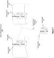
- Figures 1A and 1B illustrate flowcharts of an example method 100 for aligning and stabilizing images generated by an integrated stereo camera pair comprising a first camera and a second camera that are physically mounted to a computer system (e.g., a HMD) with images generated by a detached camera that is physically unmounted from the computer system.
- a computer system e.g., a HMD
- the embodiments are able to generate so-called "passthrough" images that have aligned content generated by different cameras.
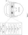
- HMD 200 can be any type of MR system 200A, including a VR system 200B or an AR system 200C. It should be noted that while a substantial portion of this disclosure is focused on the use of an HMD, the embodiments are not limited to being practiced using only an HMD. That is, any type of scanning system can be used, even systems entirely removed or separate from an HMD. As such, the disclosed principles should be interpreted broadly to encompass any type of scanning scenario or device. Some embodiments may even refrain from actively using a scanning device themselves and may simply use the data generated by the scanning device. For instance, some embodiments may at least be partially practiced in a cloud computing environment.
- HMD 200 is shown as including scanning sensor(s) 205 (i.e. a type of scanning or camera system), and HMD 200 can use the scanning sensor(s) 205 to scan environments, map environments, capture environmental data, and/or generate any kind of images of the environment (e.g., by generating a 3D representation of the environment or by generating a "passthrough" visualization).
- Scanning sensor(s) 205 may comprise any number or any type of scanning devices, without limit.
- the HMD 200 may be used to generate a parallax-corrected passthrough visualization of the user's environment.
- a "passthrough" visualization refers to a visualization that reflects what the user would see if the user were not wearing the HMD 200, regardless of whether the HMD 200 is included as a part of an AR system or a VR system.
- the passthrough visualization reflects a different or novel perspective.
- the HMD 200 may use its scanning sensor(s) 205 to scan, map, or otherwise record its surrounding environment, including any objects in the environment, and to pass that data on to the user to view.
- the passed-through data is modified to reflect or to correspond to a perspective of the user's pupils, though other perspectives may be reflected by the image as well.
- the perspective may be determined by any type of eye tracking technique or other data.
- the scanning sensor(s) 205 typically rely on its cameras (e.g., head tracking cameras, hand tracking cameras, depth cameras, or any other type of camera) to obtain one or more raw images (aka texture images) of the environment.
- these raw images may also be used to determine depth data detailing the distance from the sensor to any objects captured by the raw images (e.g., a z-axis range or measurement).
- a depth map can be computed from the depth data embedded or included within the raw images (e.g., based on pixel disparities), and passthrough images can be generated (e.g., one for each pupil) using the depth map for any reprojections.
- a depth map details the positional relationship and depths relative to objects in the environment. Consequently, the positional arrangement, location, geometries, contours, and depths of objects relative to one another can be determined. From the depth maps, a 3D representation of the environment can be generated.
- the disclosed passthrough visualizations will also enhance the user's ability to view objects within his/her environment (e.g., by displaying additional environmental conditions or image data that may not have been detectable by a human eye).
- the embodiments may generate a separate passthrough image for each one of the user's eyes. That is, two passthrough images are typically generated concurrently with one another. Therefore, while frequent reference is made to generating what seems to be a single passthrough image, the embodiments are actually able to simultaneously generate multiple passthrough images.
- scanning sensor(s) 205 include visible light camera(s) 210, low light camera(s) 215, thermal imaging camera(s) 220, potentially (though not necessarily, as represented by the dotted box in Figure 2 ) ultraviolet (UV) camera(s) 225, and potentially (though not necessarily) a dot illuminator (not shown).
- the ellipsis 230 demonstrates how any other type of camera or camera system (e.g., depth cameras, time of flight cameras, virtual cameras, depth lasers, etc.) may be included among the scanning sensor(s) 205.
- a camera structured to detect mid-infrared wavelengths may be included within the scanning sensor(s) 205.
- any number of virtual cameras that are reprojected from an actual camera may be included among the scanning sensor(s) 205 and may be used to generate a stereo pair of images. In this manner and as will be discussed in more detail later, the scanning sensor(s) 205 may be used to generate the stereo pair of images.
- the stereo pair of images may be obtained or generated as a result of performing any one or more of the following operations: active stereo image generation via use of two cameras and one dot illuminator; passive stereo image generation via use of two cameras; image generation using structured light via use of one actual camera, one virtual camera, and one dot illuminator; or image generation using a time of flight (TOF) sensor in which a baseline is present between a depth laser and a corresponding camera and in which a field of view (FOV) of the corresponding camera is offset relative to a field of illumination of the depth laser.
- TOF time of flight
- the visible light camera(s) 210 include two or more red, green, blue (RGB) cameras structured to capture light photons within the visible spectrum.
- RGB cameras are complementary metal-oxide-semiconductor (CMOS) type cameras, though other camera types may be used as well (e.g., charge coupled devices, CCD).
- CMOS complementary metal-oxide-semiconductor
- the RGB cameras are typically stereoscopic cameras, meaning that the fields of view of the two or more RGB cameras at least partially overlap with one another. With this overlapping region, images generated by the visible light camera(s) 210 can be used to identify disparities between certain pixels that commonly represent an object captured by both images. Based on these pixel disparities, the embodiments are able to determine depths for objects located within the overlapping region (i.e. "stereoscopic depth matching" or "stereo depth matching”). As such, the visible light camera(s) 210 can be used to not only generate passthrough visualizations, but they can also be used to determine object depth. In some embodiments, the visible light camera(s) 210 can capture both visible light and IR light.
- the low light camera(s) 215 are structured to capture visible light and IR light. IR light is often segmented into three different classifications, including near-IR, mid-IR, and far-IR (e.g., thermal-IR). The classifications are determined based on the energy of the IR light. By way of example, near-IR has relatively higher energy as a result of having relatively shorter wavelengths (e.g., between about 750 nm and about 1,000 nm). In contrast, far-IR has relatively less energy as a result of having relatively longer wavelengths (e.g., up to about 30,000 nm). Mid-IR has energy values in between or in the middle of the near-IR and far-IR ranges. The low light camera(s) 215 are structured to detect or be sensitive to IR light in at least the near-IR range.
- near-IR has relatively higher energy as a result of having relatively shorter wavelengths (e.g., between about 750 nm and about 1,000 nm).
- far-IR has relatively less energy as a
- the visible light camera(s) 210 and the low light camera(s) 215 (aka low light night vision cameras) operate in approximately the same overlapping wavelength range. In some cases, this overlapping wavelength range is between about 400 nanometers and about 1,000 nanometers. Additionally, in some embodiments these two types of cameras are both silicon detectors.
- the visible light camera(s) 210 are low power cameras and operate in environments where the illuminance is between about a dusk illuminance (e.g., about 10 lux) and a bright noonday sun illuminance (e.g., about 100,000 lux), or rather, the illuminance range begins at about 10 lux and increases beyond 10 lux.
- a dusk illuminance e.g., about 10 lux
- a bright noonday sun illuminance e.g., about 100,000 lux
- the low light camera(s) 215 consume more power and operate in environments where the illuminance range is between about a starlight illumination (e.g., about 1 milli lux) and a dusk illumination (e.g., about 10 lux).
- a starlight illumination e.g., about 1 milli lux
- a dusk illumination e.g., about 10 lux
- the thermal imaging camera(s) 220 are structured to detect electromagnetic radiation or IR light in the far-IR (i.e. thermal-IR) range, though some embodiments also enable the thermal imaging camera(s) 220 to detect radiation in the mid-IR range.
- the thermal imaging camera(s) 220 may be a long wave infrared imaging camera structured to detect electromagnetic radiation by measuring long wave infrared wavelengths.
- the thermal imaging camera(s) 220 detect IR radiation having wavelengths between about 8 microns and 14 microns to detect blackbody radiation from the environment and people in the camera field of view. Because the thermal imaging camera(s) 220 detect far-IR radiation, the thermal imaging camera(s) 220 can operate in any illuminance condition, without restriction.
- the uncooled thermal imaging sensor is used to generate any number of thermal images.
- the bolometer of the uncooled thermal imaging sensor can detect electromagnetic radiation across a wide spectrum, spanning the mid-IR spectrum, the far-IR spectrum, and even up to millimeter-sized waves.
- the UV camera(s) 225 are structured to capture light in the UV range.
- the UV range includes electromagnetic radiation having wavelengths between about 150 nm and about 400 nm.
- the disclosed UV camera(s) 225 should be interpreted broadly and may be operated in a manner that includes both reflected UV photography and UV induced fluorescence photography.
- visible light cameras are cameras that are primarily used for computer vision to perform head tracking. These cameras can detect visible light, or even a combination of visible and IR light (e.g., a range of IR light, including IR light having a wavelength of about 850 nm). In some cases, these cameras are global shutter devices with pixels being about 3 ⁇ m in size. Low light cameras, on the other hand, are cameras that are sensitive to visible light and near-IR. These cameras are larger and may have pixels that are about 8 ⁇ m in size or larger. These cameras are also sensitive to wavelengths that silicon sensors are sensitive to, which wavelengths are between about 350 nm to 1100 nm.
- Thermal / long wavelength IR devices i.e. thermal imaging cameras
- These cameras are sensitive to wavelengths in the 8 ⁇ m to 14 ⁇ m range.
- Some embodiments also include mid-IR cameras configured to detect at least mid-IR light. These cameras often comprise non-silicon materials (e.g., InP or InGaAs) that detect light in the 800 nm to 2 ⁇ m wavelength range.
- the disclosed embodiments may be structured to utilize numerous different camera types.
- the different camera types include, but are not limited to, visible light cameras, low light cameras, thermal imaging cameras, and UV cameras.
- Stereo depth matching may be performed using images generated from any one type or combination of types of the above listed camera types.
- the low light camera(s) 215, the thermal imaging camera(s) 220, and the UV camera(s) 225 consume relatively more power than the visible light camera(s) 210. Therefore, when not in use, the low light camera(s) 215, the thermal imaging camera(s) 220, and the UV camera(s) 225 are typically in the powered-down state in which those cameras are either turned off (and thus consuming no power) or in a reduced operability mode (and thus consuming substantially less power than if those cameras were fully operational). In contrast, the visible light camera(s) 210 are typically in the powered-up state in which those cameras are by default fully operational.
- any number of cameras may be provided on the HMD 200 for each of the different camera types. That is, the visible light camera(s) 210 may include 1, 2, 3, 4, 5, 6, 7, 8, 9, 10, or more than 10 cameras. Often, however, the number of cameras is at least 2 so the HMD 200 can perform stereoscopic depth matching, as described earlier. Similarly, the low light camera(s) 215, the thermal imaging camera(s) 220, and the UV camera(s) 225 may each respectively include 1, 2, 3, 4, 5, 6, 7, 8, 9, 10, or more than 10 corresponding cameras.
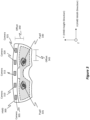
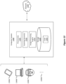
- FIG 3 illustrates an example HMD 300, which is representative of the HMD 200 from Figure 2 .
- HMD 300 is shown as including multiple different cameras, including cameras 305, 310, 315, 320, and 325. Cameras 305-325 are representative of any number or combination of the visible light camera(s) 210, the low light camera(s) 215, the thermal imaging camera(s) 220, and the UV camera(s) 225 from Figure 2 . While only 5 cameras are illustrated in Figure 3 , HMD 300 may include more or less than 5 cameras.
- the cameras can be located at specific positions on the HMD 300.
- a first camera e.g., perhaps camera 320
- the HMD 300 is disposed on the HMD 300 at a position above a designated left eye position of any users who wear the HMD 300 relative to a height direction of the HMD.
- the camera 320 is positioned above the pupil 330.
- the first camera e.g., camera 320
- the first camera is additionally positioned above the designated left eye position relative to a width direction of the HMD. That is, the camera 320 is positioned not only above the pupil 330 but also in-line relative to the pupil 330.
- a camera may be placed directly in front of the designated left eye position.
- a camera may be physically disposed on the HMD 300 at a position in front of the pupil 330 in the z-axis direction.
- the second camera may be disposed on the HMD at a position above a designated right eye position of any users who wear the HMD relative to the height direction of the HMD.
- the camera 310 is above the pupil 335.
- the second camera is additionally positioned above the designated right eye position relative to the width direction of the HMD.
- a camera may be placed directly in front of the designated right eye position.
- a camera may be physically disposed on the HMD 300 at a position in front of the pupil 335 in the z-axis direction.
- HMD 300 When a user wears HMD 300, HMD 300 fits over the user's head and the HMD 300's display is positioned in front of the user's pupils, such as pupil 330 and pupil 335. Often, the cameras 305-325 will be physically offset some distance from the user's pupils 330 and 335. For instance, there may be a vertical offset in the HMD height direction (i.e. the "Y" axis), as shown by offset 340. Similarly, there may be a horizontal offset in the HMD width direction (i.e. the "X" axis), as shown by offset 345.
- HMD 300 is configured to provide passthrough image(s) for the user of HMD 300 to view. In doing so, HMD 300 is able to provide a visualization of the real world without requiring the user to remove or reposition HMD 300. These passthrough image(s) effectively represent the same view the user would see if the user were not wearing HMD 300. Cameras 305-325 are used to provide these passthrough image(s).
- raw images aka texture images
- the parallax correction includes any number of corrections, which will be discussed in more detail later.
- initially method 100 includes an act (act 105) of generating a first image using the first camera, generating a second image using the second camera, and generating a third image using the detached camera.
- the first camera may be any one of the cameras 305-325 illustrated in Figure 3
- the second camera may be any other one of the cameras 305-325.
- the first and second cameras may be any of the camera modalities mentioned earlier (e.g., thermal imaging, etc.).
- the detached camera on the other hand, will not be any of the cameras 305-325. Instead, the detached camera is physically separated or unmounted from the HMD.
- Figure 4 is illustrative of such a scenario.
- the first camera, the second camera, or even the detached camera mentioned in method act 105 may all be visible light cameras, thermal imaging cameras, low light cameras, UV cameras, or, alternatively, any combination of visible light cameras, low light cameras, thermal imaging cameras, or UV cameras.
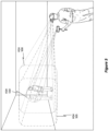
- FIG 4 shows an example environment 400 in which an HMD 405 is operating.
- HMD 405 is representative of HMD 300 of Figure 3 and HMD 200 of Figure 2 .
- HMD 405 is shown as including an integrated stereo camera pair 410 comprising a first camera 415 and a second camera 420, which cameras are representative of the cameras mentioned in method act 105 of Figure 1A and which are representative of the cameras discussed thus far.
- Figure 4 also shows a detached camera 425, which is representative of the detached camera mentioned in method act 105.
- the detached camera 425 is physically unmounted from the HMD 405 such that it is able to move independently of any motion of the HMD 405.
- the detached camera 425 is separated from the HMD 405 by a distance 430.
- This distance 430 may be any distance, but typically it is less than 1.5 meters (i.e. the distance 430 is at most 1.5 meters).
- the various different cameras are being used in a scenario where objects in the environment 400 are relatively far away from the HMD 405, as shown by the distance 435.
- the relationship between the distance 435 and the distance 430 will be discussed in more detail later.
- the first camera 415 is capturing images of the environment 400 from a first perspective 440
- the second camera 420 is capturing images of the environment 400 from a second perspective 445
- the detached camera 425 is capturing images of the environment 400 from a third perspective 450.
- the embodiments initially rely on an assumption that the detached camera 425 is co-located 455 with the stereo camera pair 410.
- co-located 455 it is meant that the detached camera 425 is assumed to be positioned at the same location as the first camera 415 (for one set of operations) and is assumed to be positioned at the same location as the second camera 420 (for a different set of operations) on the HMD 405.
- Being co-located 455 does not mean that the detached camera 425 has the same 3 degree of freedom (3 DOF) pose or perspective as the first or second cameras 415 and 420; rather, it means that the physical placement of the detached camera 425 is assumed to be at the same location as the first and second camera 420 (i.e. same distance 435).
- 3 DOF 3 degree of freedom
- Figure 5 shows a scenario in which the different cameras mentioned in Figure 4 are now being used to generate respective images.
- the first camera 415 of Figure 4 has a FOV 500 and is generating an image based on the FOV 500.
- the second camera 420 of Figure 4 has a FOV 505 and is generating an image based on the FOV 505.
- the detached camera 425 has a FOV 510 and is generating an image based on the FOV 510.
- the size of the FOV 500 is the same as the size of the FOV 505. In some embodiments, the size of FOV 500 may be different from the size of FOV 505. In some embodiments, the size of FOV 510 is smaller than either one of the sizes of FOVs 500 or 505. In some embodiments, the size of FOV 510 may be the same as either one or both of the sizes of FOVs 500 and 505.
- the size of FOV 510 is less than about a 20-degree horizontal spread, such as perhaps a 19, 18, 17, 16, 15, 14, 13, 12, 11, 10, or less than 10-degree horizontal spread. In some cases, either one or both of the sizes of FOVs 500 and 505 is less than about a 65-degree horizontal spread, such as perhaps a 60, 55, 50, 45, 40, or less than 40-degree horizontal spread.
- Figure 6 shows the resulting images, which are representative of the images discussed in method act 105 of Figure 1A .
- Figure 6 shows a first image 600, which was generated by the first camera 415 of Figure 4 .
- the second image 605 was generated by the second camera 420, and the third image 610 was generated by the detached camera 425.
- Figure 6 shows how the first image 600 has a resolution 615, the second image 605 has a resolution 620, and the third image 610 has a resolution 625.
- the resolution 615 is the same as the resolution 620
- the resolution 625 is the same as the resolutions 615 and 620.
- the resolutions may all be different or two of them may be the same while the remaining resolution is different. Because the sizes of the FOVs of the different cameras may be different, the size of the resulting images may also be different. Despite the sizes being different, the resolutions may still be the same. For instance, Figure 6 shows how the third image 610 is smaller than either one of the first image 600 or the second image 605. Notwithstanding this difference in size, the resolutions may all still be the same. Consequently, each pixel included in the third image 610 is smaller and provides a heightened level of detail as compared to each pixel in either the first image 600 or the second image 605.
- the resolution 625 of the third image 610 may be the same as the resolution 615 of the first image 600 (or the resolution 620 of the second image 605) such that, as a result of the FOV of the third image 610 (e.g., FOV 510 in Figure 5 ) being smaller than the FOV of the first image (e.g., FOV 500), each pixel in the third image 610 is smaller than each pixel in the first image 600 (and also the second image 605).
- method 100 further includes an act (act 110) of computing a first rotation base matrix of the third image relative to the first image.
- act 110 of computing a first rotation base matrix of the third image relative to the first image.
- act 115 of computing a second rotation base matrix of the third image relative to the second image.
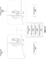
- the embodiments first perform a feature matching process 700, as shown in Figure 7 .
- Figure 7 shows a first image 705, a second image 710, and a third image 715, which correspond to the first image 600, the second image 605, and the third image 610 of Figure 6 , respectively.
- the embodiments identify so-called "feature points" within the different images.
- a “feature point” refers to discrete and identifiable points included within an object or image. Examples of feature points include corners, edges, or other geometric contours having a stark contrast with other areas of the environment.
- the dark circles in each of the images shown in Figure 7 correspond to the corners where two walls meet and are considered to be feature points. While only a few feature points are illustrated in Figure 7 , one will appreciate how the embodiments are able to identify any number of feature points in an image.
- Identifying feature points may be performed using any type of image analysis, image segmentation, or perhaps even machine learning (ML). Any type of ML algorithm, model, or machine learning may be used to identify feature points.
- machine learning or to a ML model may include any type of machine learning algorithm or device, neural network (e.g., convolutional neural network(s), multilayer neural network(s), recursive neural network(s), deep neural network(s), dynamic neural network(s), etc.), decision tree model(s) (e.g., decision trees, random forests, and gradient boosted trees), linear regression model(s) or logistic regression model(s), support vector machine(s) (“SVM”), artificial intelligence device(s), or any other type of intelligent computing system. Any amount of training data may be used (and perhaps later refined) to train the machine learning algorithm to dynamically perform the disclosed operations.
- neural network e.g., convolutional neural network(s), multilayer neural network(s), recursive neural network(s), deep neural network(s), dynamic neural network(s), etc
- Figure 7 specifically identifies feature point 720A in the first image 705.
- the feature point 720B in the second image 710 corresponds to the feature point 720A.
- the feature point 720C identified in the third image 715 corresponds to both the feature points 720A and 720B.
- "correspond" means that the three identified feature points represent the same area or object in the environment (i.e. the specific portion of the corner wall).
- the embodiments are able to analyze the three different images, identify different feature points, and then perform feature point matching 725 to link or associate corresponding feature points with one another.
- the dotted lined labeled as feature point matching 725 symbolically represents the association between the feature points 720A, 720B, and 720C.
- Detecting corresponding feature points requires that the FOVs of the different cameras at least partially overlap with one another, as was shown in Figure 5 . If there is no overlap or not a sufficient amount of overlap between the different FOVs, then the feature matching process 700 may not be able to detect a sufficient number of feature points. If there is a sufficient level of overlap, on the other hand, then the embodiments can detect corresponding feature points.
- the embodiments rely on an assumption that the three different cameras are co-located with one another, as was introduced in Figure 4 .
- the embodiments assume the third camera is co-located with the first camera and separately assume the third camera is co-located with the second camera.
- the embodiments assume the first and third cameras are located at the same position but that the two cameras currently have different poses or rotational alignments.
- the embodiments assume the second and third cameras are located at the same position but that the two cameras currently have different poses or rotational alignments.
- This co-location assumption is valid when the distance 435 shown in Figure 4 between the cameras and objects in the environment is sufficiently large.
- the assumption may break down when the distance 435 is smaller than a minimum threshold distance.
- the minimum threshold distance may be set to any distance, but the assumption will typically be operational for distances over about 3 meters.
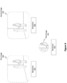
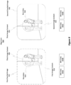
- Figure 8 shows a third image 800, which is representative of the third images discussed thus far (i.e. the one generated by the detached camera), and a first image 805, which is representative of the first images discussed thus far (i.e. the one generated by the first camera).
- the embodiments assume that the detached camera and the first camera are co-located 810 with one another such that there is only a rotational alignment difference, or a 3 DOF 815 difference, between the third image 800 and the first image 805.
- the embodiments then compute a first rotation base matrix 820 between the third image 800 and the first image 805.
- the first rotation base matrix 820 details the angular difference between the position of the third image 800 and the first image 805. Stated differently, the first rotation base matrix 820 provides a mapping on the translational or angular movement that would be required to go from the perspective of the third image 800 to the perspective of the first image 805.
- computing the first rotation base matrix 820 of the third image 800 relative to the first image 805 is performed based on an incorrect, but acceptable, assumption that the third camera and the first camera are co-located 810 with one another (thus there is no translational mapping required, only a rotational mapping). Furthermore, computing the first rotation base matrix 820 of the third image 800 relative to the first image 805 may be performed based on a result of a feature matching process (e.g., feature matching process 700 of Figure 7 ) being performed between the first image 805 and the third image 800.
- a feature matching process e.g., feature matching process 700 of Figure 7
- the first rotation base matrix 820 can be considered a type of motion model.
- a motion model is a type of transformation matrix that enables a model, a known scene, or an object to be projected onto a different model, scene, or object.
- the motion model may simply be a rotational motion model.
- the embodiments are able to shift one image by any number of pixels (e.g., perhaps 5 pixels to the left and 10 pixels up) in order to overlay one image onto another image. For instance, once the feature points are identified, the embodiments can identify the pixel coordinates of those feature points or correspondences. Once the coordinates are identified, then the embodiments can generate the first rotation base matrix 820 by determining the amount or level of shifting required in order to align the feature points from the third image to the feature points of the first image.
- the motion model may be more complex, such as in the form of a similarity transform model.
- the similarity transform model may be configured to allow for (i) rotation of either one of the integrated camera image (i.e. the first image) or the detached camera image (i.e. the third image), (ii) scaling of the first image or the third image, or (iii) homographic transformations of the first image or the third image.
- the similarity transform model approach may be used to determine the first rotation base matrix 820.
- Similar operations may be performed as between the third image 800 and the second image 825, as shown in Figure 8 .
- the embodiments initially assume the third image 800 is co-located 830 with the second image 825. Based on this co-located 830 assumption, the embodiments determine there is only a 3 DOF 835 difference between the third image 800 and the second image 825. With that assumption, the embodiments are able to generate a second rotation base matrix 840 to rotationally translate the perspective of the third image 800 until it aligns with the perspective of the second image 825 based on the pixel locations or coordinates of the detected and corresponding feature points present in those two images.
- computing the second rotation base matrix 840 of the third image 800 relative to the second image 825 may be performed based on an incorrect, but acceptable, assumption that the third camera and the second camera are co-located 830 with one another. Furthermore, computing the second rotation base matrix 840 of the third image 800 relative to the second image 825 may be performed based on a result of a feature matching process (e.g., feature matching process 700 of Figure 7 ) being performed between the second image 825 and the third image 800.
- a feature matching process e.g., feature matching process 700 of Figure 7
- method 100 of Figure 1A continues with an act 120 of aligning the third image to the first image using the first rotation base matrix and aligning the third image to the second image using the second rotation base matrix.
- act 120 involves manipulating the different images so that they are actually overlaid or positioned on one another, perhaps in a layered manner.
- method 100 continues in Figure 1B with an act (act 125) of actually generating a first overlaid image by overlaying the third image onto the first image (based on the alignment process) and an act (act 130) of generating a second overlaid image by overlaying the third image onto the second image (based on that alignment process).
- act 125 an act of actually generating a first overlaid image by overlaying the third image onto the first image (based on the alignment process)
- act 130 act of generating a second overlaid image by overlaying the third image onto the second image (based on that alignment process).
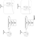
- Figure 9 is representative of these two acts.
- Figure 9 shows an alignment 900 process representative of the alignment processes described in method acts 120 through 130 of Figures 1A and 1B .
- the alignment 900 process involves using the previously computed first rotation base matrix to align third image content 905 with the first image content 910 so as to generate a single, integrated (i.e. perhaps not layered) first overlaid image 915.
- a boundary 920 is visually displayed in the first overlaid image 915 to emphasize or identify pixels that originated from the first image (i.e. the first image content 910) and pixels that originated from the third image (i.e. the third image content 905).
- the resolution of the smaller FOV third image was the same as the resolution of the larger FOV first image. Consequently, the pixels of the third image will give content a sharper, clearer, or more crisp visualization as compared to pixels of the first image. Therefore, by overlaying the third image content 905 onto the first image content 910, the section of the first overlaid image 915 corresponding to the third image content 905 may appear to be clearer or of higher detail than other portions of the first overlaid image 915 (e.g., those pixels corresponding to the first image content 910). Similar operations may be performed as between the third image and the second image.
- the alignment 900 process may additionally involve using the previously computed second rotation base matrix to align third image content 925 with the second image content 930 so as to generate a single, integrated (i.e. perhaps not layered) second overlaid image 935.
- a boundary 940 is visually displayed in the second overlaid image 935 to emphasize or identify pixels that originated from the second image (i.e. the second image content 930) and pixels that originated from the third image (i.e. the third image content 925).
- the alignment 900 process may be dependent on inertial measurement unit (IMU) data obtained from any of the first, second, or detached cameras.
- IMU data 945A is IMU data obtained from an IMU of the first camera and describes movement of the first camera.
- IMU data 945B is IMU data obtained from an IMU of the detached camera and describes movement of the detached camera.
- IMU data 945C is IMU data obtained from an IMU of the second camera and describes movement of the second camera.
- the embodiments are able to utilize the IMU data 945A, 945B, and 945C to update the respective first or second rotational base matrices to account for the new movement. For instance, by multiplying the first rotational base matrix against matrix data generated based on the IMU data 945A and 945B, the embodiments are able to undo the effects of movement of either one of the first camera or the detached camera. Similarly, by multiplying the second rotational base matrix against matrix data generated based on the IMU data 945C and 945B, the embodiments are able to undo the effects of movement of either one of the second camera or the detached camera.
- aligning the third image to the first image using the first rotation base matrix may be performed using inertial measurement unit (IMU) data from the first camera and IMU data from the third camera, with similar operations for the second and detached cameras.
- IMU inertial measurement unit
- the alignment 900 process may be based on the results of the feature matching operations as well as utilizing the rotational base matrices and possibly even IMU data.
- method 100 also includes an act (act 135) of performing a first parallax correction on the first overlaid image by modifying the first overlaid image from a first perspective to a first new perspective.
- act 135 In parallel or in serial with act 135, method 100 includes an act (act 140) of performing a second parallax correction on the second overlaid image by modifying the second overlaid image from a second perspective to a second new perspective. Both acts 135 and 140 are illustrated in Figure 1B using a dotted line to show that these acts are optional.
- the computer system implementing the disclosed operations may be a head-mounted device (HMD) worn by a user.
- the first new perspective may correspond to one of a left eye pupil or a right eye pupil
- the second new perspective may correspond to the other one of the left eye pupil or the right eye pupil.
- Another optional act involves the act 145 of displaying the first overlaid image and the second overlaid image.
- Figures 10 , 11 , and 12 are illustrative of some of these operations.
- Figure 10 shows an overlaid image 1000, which may be either one of the first overlaid image 915 or the second overlaid image 935 from Figure 9 and which may be the overlaid images discussed in method 100.
- the overlaid image 1000 is shown as having an original perspective 1005.
- the embodiments are able to perform a parallax correction 1010 to transform the original perspective 1005 of the overlaid image 1000 into a new or novel perspective.
- the parallax correction 1010 involves the use of a depth map in order to reproject the image content to a new perspective. Additionally, the parallax correction 1010 is shown as including any one or more of a number of different operations. For instance, the parallax correction 1010 may involve distortion corrections 1015 (e.g., to correct for concave or convex wide or narrow angled camera lenses), epipolar transforms 1020 (e.g., to parallelize the optical axes of the cameras), and/or reprojection transforms 1025 (e.g., to reposition the optical axes so as to be essentially in front of or in-line with the user's pupils).
- distortion corrections 1015 e.g., to correct for concave or convex wide or narrow angled camera lenses
- epipolar transforms 1020 e.g., to parallelize the optical axes of the cameras
- reprojection transforms 1025 e.g., to reposition the optical axes so as to be essentially in front of
- the parallax correction 1010 includes performing depth computations to determine the depth of the environment and then reprojecting images to a determined location or as having a determined perspective.
- the phrases "parallax correction” and “image synthesis” may be interchanged with one another and may include performing stereo passthrough parallax correction and/or image reprojection parallax correction.
- the reprojections are based on the original perspective 1005 of the overlaid image 1000 relative to the surrounding environment. Based on the original perspective 1005 and the depth maps that are generated, the embodiments are able to correct parallax by reprojecting a perspective embodied by the overlaid images to coincide with a new perspective, as shown by the parallax-corrected image 1030 and the new perspective 1035.
- the new perspective 1035 is that of one of the user's pupils 330 and 335 from Figure 3 .
- Some embodiments perform three-dimensional (3D) geometric transforms on the overlaid images to transform the perspectives of the overlaid images in a manner so as to correlate with the perspectives of the user's pupils 330 and 335. Additionally, the 3D geometric transforms rely on depth computations in which the objects in the HMD's environment are mapped out to determine their depths as well as the perspective. Based on these depth computations and perspective, the embodiments are able to three-dimensionally reproject or three-dimensionally warp the overlaid images in such a way so as to preserve the appearance of object depth in the parallax-corrected image 1030 (i.e. a type of passthrough image), where the preserved object depth substantially matches, corresponds, or visualizes the actual depths of objects in the real world. Accordingly, the degree or amount of the parallax correction 1010 is at least partially dependent on the degree or amount of the offsets 340 and 345 from Figure 3 .
- the embodiments By performing the parallax correction 1010, the embodiments effectively create "virtual" cameras having positions that are in front of the user's pupils 330 and 335.
- the embodiments programmatically transform images generated by camera 305, or rather the perspectives of those images, so the perspectives appear as though camera 305 were actually positioned immediately in front of pupil 335. That is, even though camera 305 does not actually move, the embodiments are able to transform images generated by camera 305 so those images have the appearance as if camera 305 were positioned in front of pupil 335.
- the parallax correction 1010 relies on a full depth map to perform the reprojections while in other cases the parallax correction 1010 relies on a planar depth map to perform the reprojections.
- Figure 11 illustrates an example usage of a full depth map while Figure 12 illustrates an example usage of a planar depth map.
- FIG. 11 this figure illustrates a scenario involving a full depth map reprojection 1100.
- a third image 1105 which is representative of the third images discussed thus far. Similar to the other third images, third image 1105 is bounded by a circle 1110 (of course, any other shape may be used) comprising any number of pixels 1115.
- a circle 1110 (of course, any other shape may be used) comprising any number of pixels 1115.
- One pixel in particular is emphasized and is shown by the center pixel 1120 (i.e. the pixel located at the center of the circle 1110).
- the embodiments determine a depth 1125 corresponding to the depth of the center pixel 1120 and then attribute 1130 that single depth 1125 to all of the pixels bounded by the circle 1110, as shown by the uniform depth 1135 illustration.
- the resulting depth map will appear as the full depth map 1140, where the color gradients reflect different depth values and where the pixels corresponding to those bounded by the circle 1110 are all given the same shading such that they all have the same depth value.
- the full depth map 1140 is then used to perform the reprojections involved in the parallax correction operations discussed earlier.
- the embodiments prevent skewing from occurring on that image content as a result of performing parallax correction.
- some embodiments use a fixed depth map to perform a fixed depth map reprojection 1200 as shown in Figure 12 .
- a third image 1205 is again shown, which image is representative of the other third images discussed thus far.
- the embodiments select the depth of a particular pixel from the third image 1205.
- the center pixel 1210 is selected, and a depth 1215 of that center pixel 1210 is identified (or perhaps some other pixel or group of pixel's depth).
- the embodiments then attribute that single depth to all of the pixels of a depth map to generate the fixed depth map 1220.
- all of the depth pixels in the fixed depth map 1220 are assigned or attributed the same depth, which is the depth 1215 of the center pixel 1210 (or some other selected pixel).
- the common shading across the entire fixed depth map 1220 symbolizes the uniform depth values or planar depth values in the depth map.
- this depth map may then be used to perform a reprojection (e.g., a planar reprojection) on the overlaid image using the fixed depth map 1220.
- a reprojection e.g., a planar reprojection
- reprojecting the overlaid image (e.g., overlaid image 1000 from Figure 10 ) to generate parallax-corrected image 1030 may be performed using a full depth map 1140 or a fixed depth map 1220.
- the first parallax correction and/or the second parallax correction mentioned in method acts 135 and 140 of Figure 1B may include reprojecting content based on a fixed depth plane or, alternatively, based on a full depth map.
- the embodiments are able to perform the first (or second) parallax correction mentioned in acts 135 and 140 of Figure 1B on the first (or second) overlaid image.
- Such parallax correction may involve a number of different operations.
- one operation includes identifying pixels included within at least a portion (or potentially the entirety) of the third image (e.g., the embodiments may identify all of the pixels bounded by the circle 1110 of Figure 11 ).
- the portion of the third image may be a circle such that the identified pixels form the circle. In other cases, the portion may form a different shape, such as any polygon.
- Another operation includes selecting a depth corresponding to at least one of the identified pixels (e.g., the center pixel 1120 of Figure 11 ). That is, the selected depth may be the depth of the center pixel of the circle mentioned earlier.
- Another operation includes attributing the depth (e.g., attribute 1130 of Figure 11 ) to all of the identified pixels, as shown by the uniform depth 1135.
- another operation involves reprojecting the identified pixels using the attributed depth.
- the disclosed embodiments are able to align images from different cameras and then perform parallax correction on the aligned images in order to generate passthrough images having new perspectives. Such operations significantly enhance the quality of images by enabling new and dynamic image content to be displayed.
- Computer system 1300 may take various different forms.
- computer system 1300 may be embodied as a tablet 1300A, a desktop or laptop 1300B, a wearable device 1300C (e.g., such as any of the disclosed HMDs), a mobile device, a standalone device, or any other embodiment as shown by the ellipsis 1300D.
- Computer system 1300 may also be a distributed system that includes one or more connected computing components/devices that are in communication with computer system 1300.
- computer system 1300 includes various different components.
- Figure 13 shows that computer system 1300 includes one or more processor(s) 1305 (aka a "hardware processing unit"), scanning sensor(s) 1310 (e.g., such as the scanning sensor(s) 205 of Figure 2 ), an image processing engine 1315, and storage 1320.
- processor(s) 1305 aka a "hardware processing unit”
- scanning sensor(s) 1310 e.g., such as the scanning sensor(s) 205 of Figure 2
- an image processing engine 1315 e.g., such as the scanning sensor(s) 205 of Figure 2
- processor(s) 1305 the functionality described herein can be performed, at least in part, by one or more hardware logic components (e.g., the processor(s) 1305).
- illustrative types of hardware logic components/processors include Field-Programmable Gate Arrays ("FPGA"), Program-Specific or Application-Specific Integrated Circuits (“ASIC”), Program-Specific Standard Products (“ASSP”), System-On-A-Chip Systems (“SOC”), Complex Programmable Logic Devices (“CPLD”), Central Processing Units (“CPU”), Graphical Processing Units (“GPU”), or any other type of programmable hardware.
- FPGA Field-Programmable Gate Arrays
- ASIC Program-Specific or Application-Specific Integrated Circuits
- ASSP Program-Specific Standard Products
- SOC System-On-A-Chip Systems
- CPLD Complex Programmable Logic Devices
- CPU Central Processing Unit
- GPU Graphical Processing Units
- any type of depth detection may be utilized by the computer system 1300 and by the scanning sensor(s) 1310.
- Examples include, but are not limited to, stereoscopic depth detection (both active illumination (e.g., using a dot illuminator), structured light illumination (e.g., 1 actual camera, 1 virtual camera, and 1 dot illuminator), and passive (i.e. no illumination)), time of flight depth detection (with a baseline between the laser and the camera, where the field of view of the camera does not perfectly overlap the field of illumination of the laser), range finder depth detection, or any other type of range or depth detection.
- stereoscopic depth detection both active illumination (e.g., using a dot illuminator), structured light illumination (e.g., 1 actual camera, 1 virtual camera, and 1 dot illuminator), and passive (i.e. no illumination)
- time of flight depth detection with a baseline between the laser and the camera, where the field of view of the camera does not perfectly overlap the field of illumination of the
- the image processing engine 1315 may be configured to perform any of the method acts discussed in connection with method 100 of Figure 1 .
- the image processing engine 1315 includes a ML algorithm. That is, ML may also be utilized by the disclosed embodiments, as discussed earlier. ML may be implemented as a specific processing unit (e.g., a dedicated processing unit as described earlier) configured to perform one or more specialized operations for the computer system 1300.
- ML may be implemented as a specific processing unit (e.g., a dedicated processing unit as described earlier) configured to perform one or more specialized operations for the computer system 1300.
- the terms "executable module,” “executable component,” 29 “component,” “module,” “model,” or “engine” can refer to hardware processing units or to software objects, routines, or methods that may be executed on computer system 1300.
- ML models and/or the processor(s) 1305 can be configured to perform one or more of the disclosed method acts or other functionalities.
- Storage 1320 may be physical system memory, which may be volatile, non-volatile, or some combination of the two.
- the term "memory” may also be used herein to refer to non-volatile mass storage such as physical storage media. If computer system 1300 is distributed, the processing, memory, and/or storage capability may be distributed as well.
- Storage 1320 is shown as including executable instructions (i.e. code 1325).
- the executable instructions represent instructions that are executable by the processor(s) 1305 (or perhaps even the image processing engine 1315) of computer system 1300 to perform the disclosed operations, such as those described in the various methods.
- the disclosed embodiments may comprise or utilize a special-purpose or general-purpose computer including computer hardware, such as, for example, one or more processors (such as processor(s) 1305) and system memory (such as storage 1320), as discussed in greater detail below.
- Embodiments also include physical and other computer-readable media for carrying or storing computer-executable instructions and/or data structures. Such computer-readable media can be any available media that can be accessed by a general-purpose or special-purpose computer system.
- Computer-readable media that store computer-executable instructions in the form of data are "physical computer storage media” or a “hardware storage device.”
- Computer-readable media that carry computer-executable instructions are "transmission media.”
- the current embodiments can comprise at least two distinctly different kinds of computer-readable media: computer storage media and transmission media.
- Computer storage media are computer-readable hardware storage devices, such as RAM, ROM, EEPROM, CD-ROM, solid state drives (“SSD”) that are based on RAM, Flash memory, phase-change memory (“PCM”), or other types of memory, or other optical disk storage, magnetic disk storage or other magnetic storage devices, or any other medium that can be used to store desired program code means in the form of computer-executable instructions, data, or data structures and that can be accessed by a general-purpose or special-purpose computer.
- RAM random access memory
- ROM read-only memory
- EEPROM electrically erasable programmable read-only memory
- CD-ROM Compact Disk Read Only Memory
- SSD solid state drives
- PCM phase-change memory
- Computer system 1300 may also be connected (via a wired or wireless connection) to external sensors (e.g., one or more remote cameras) or devices via a network 1330.
- computer system 1300 can communicate with any number devices or cloud services to obtain or process data.
- network 1330 may itself be a cloud network.
- computer system 1300 may also be connected through one or more wired or wireless networks 1330 to remote/separate computer systems(s) that are configured to perform any of the processing described with regard to computer system 1300.
- a "network,” like network 1330, is defined as one or more data links and/or data switches that enable the transport of electronic data between computer systems, modules, and/or other electronic devices.
- a network either hardwired, wireless, or a combination of hardwired and wireless
- Computer system 1300 will include one or more communication channels that are used to communicate with the network 1330.
- Transmissions media include a network that can be used to carry data or desired program code means in the form of computer-executable instructions or in the form of data structures. Further, these computer-executable instructions can be accessed by a general-purpose or special-purpose computer. Combinations of the above should also be included within the scope of computer-readable media.
- program code means in the form of computer-executable instructions or data structures can be transferred automatically from transmission media to computer storage media (or vice versa).
- program code means in the form of computer-executable instructions or data structures received over a network or data link can be buffered in RAM within a network interface module (e.g., a network interface card or "NIC") and then eventually transferred to computer system RAM and/or to less volatile computer storage media at a computer system.
- NIC network interface card
- Computer-executable (or computer-interpretable) instructions comprise, for example, instructions that cause a general-purpose computer, special-purpose computer, or special-purpose processing device to perform a certain function or group of functions.
- the computer-executable instructions may be, for example, binaries, intermediate format instructions such as assembly language, or even source code.
- embodiments may be practiced in network computing environments with many types of computer system configurations, including personal computers, desktop computers, laptop computers, message processors, hand-held devices, multi-processor systems, microprocessor-based or programmable consumer electronics, network PCs, minicomputers, mainframe computers, mobile telephones, PDAs, pagers, routers, switches, and the like.
- the embodiments may also be practiced in distributed system environments where local and remote computer systems that are linked (either by hardwired data links, wireless data links, or by a combination of hardwired and wireless data links) through a network each perform tasks (e.g. cloud computing, cloud services and the like).
- program modules may be located in both local and remote memory storage devices.
Landscapes
- Engineering & Computer Science (AREA)
- Physics & Mathematics (AREA)
- General Physics & Mathematics (AREA)
- Multimedia (AREA)
- Signal Processing (AREA)
- Computer Vision & Pattern Recognition (AREA)
- Theoretical Computer Science (AREA)
- Studio Devices (AREA)
Claims (15)
- Verfahren (100) zum Ausrichten und Stabilisieren von Bildern, die von einem integrierten Stereokamerapaar (410) erzeugt werden, umfassend eine erste Kamera (415) und eine zweite Kamera (420), die physisch an einem Computersystem für gemischte Realität (1300) montiert sind, mit Bildern, die von einer separaten Kamera (425) erzeugt werden, die physisch nicht an dem Computersystem (1300) montiert ist, wobei das Verfahren (100) Folgendes umfasst:Erzeugen (105) eines ersten Bildes (600) unter Verwendung der ersten Kamera (415), Erzeugen eines zweiten Bildes (605) unter Verwendung der zweiten Kamera (420) und Erzeugen eines dritten Bildes (610) unter Verwendung der separaten Kamera (425);Berechnen (110) einer ersten Basis-Drehmatrix (820) des dritten Bildes (610) relativ zu dem ersten Bild (600), wobei das Berechnen der ersten Basis-Drehmatrix des dritten Bildes relativ zu dem ersten Bild basierend auf einer falschen, aber akzeptablen Annahme durchgeführt wird, dass die separate Kamera und die erste Kamera sich in derselben Position befinden;Berechnen (115) einer zweiten Basis-Drehmatrix (840) des dritten Bildes (610) relativ zu dem zweiten Bild (605);Ausrichten (120) des dritten Bildes (610) an dem ersten Bild (600) unter Verwendung der ersten Basis-Drehmatrix (820) und Ausrichten des dritten Bildes (610) an dem zweiten Bild (605) unter Verwendung der zweiten Basis-Drehmatrix (840);Erzeugen (125) eines ersten überlagerten Bildes (915) durch Überlagern des dritten Bildes (610) auf dem ersten Bild (600) basierend auf der Ausrichtung;Erzeugen (130) eines zweiten überlagerten Bildes (935) durch Überlagern des dritten Bildes (610) auf dem zweiten Bild (605) basierend auf der Ausrichtung;Durchführen (135) einer ersten Parallaxenkorrektur an dem ersten überlagerten Bild (915) durch Modifizieren des ersten überlagerten Bildes (915) von einer ersten Perspektive zu einer ersten neuen Perspektive;Durchführen (140) einer zweiten Parallaxenkorrektur an dem zweiten überlagerten Bild (935) durch Modifizieren des zweiten überlagerten Bildes (935) von einer zweiten Perspektive zu einer zweiten neuen Perspektive; undAnzeigen (145) des ersten überlagerten Bildes (915) und des zweiten überlagerten Bildes (935).
- Verfahren nach Anspruch 1, wobei die erste Parallaxenkorrektur und/oder die zweite Parallaxenkorrektur das erneute Projizieren von Inhalten basierend auf einer Ebene mit fester Tiefe einschließt.
- Verfahren nach Anspruch 1, wobei die erste Parallaxenkorrektur und/oder die zweite Parallaxenkorrektur das erneute Projizieren von Inhalten basierend auf einer Karte mit voller Tiefe einschließt.
- Verfahren nach Anspruch 1, wobei die erste Kamera und die zweite Kamera beide Wärmebildkameras sind.
- Verfahren nach Anspruch 1, wobei das Computersystem eine von einem Benutzer getragene, am Kopf montierte Vorrichtung (HMD) ist, wobei die erste neue Perspektive einer von einer Pupille des linken Auges oder einer Pupille des rechten Auges des Benutzers entspricht und wobei die zweite neue Perspektive der anderen der Pupille des linken Auges oder der Pupille des rechten Auges des Benutzers entspricht.
- Verfahren nach Anspruch 1, wobei die Berechnung der ersten Basis-Drehmatrix des dritten Bildes relativ zu dem ersten Bild basierend auf einem Ergebnis eines Merkmalsabgleichs durchgeführt wird, der zwischen dem ersten Bild und dem dritten Bild durchgeführt wird.
- Verfahren nach Anspruch 1, wobei die Durchführung der ersten Parallaxenkorrektur auf dem ersten überlagerten Bild durchgeführt wird durch:Identifizieren von Pixeln, die in das dritte Bild eingeschlossen sind;Auswählen einer Tiefe, die mindestens einem der identifizierten Pixel entspricht;Zuweisen der Tiefe zu allen identifizierten Pixeln; undwenn die erste Parallaxenkorrektur durchgeführt wird, erneutes Projizieren der identifizierten Pixel unter Verwendung der zugewiesenen Tiefe.
- Verfahren nach Anspruch 7, wobei das dritte Bild durch einen Kreis begrenzt ist, so dass die identifizierten Pixel den Kreis bilden.
- Verfahren nach Anspruch 8, wobei die ausgewählte Tiefe eine Tiefe eines Pixels im Mittelpunkt des Kreises ist.
- Verfahren nach Anspruch 1, wobei das Ausrichten des dritten Bildes an dem ersten Bild unter Verwendung der ersten Basis-Drehmatrix durchgeführt wird, wobei Daten einer Trägheitsmesseinheit (IMU) von der ersten Kamera und IMU-Daten von der dritten Kamera verwendet werden.
- Verfahren nach Anspruch 1, wobei die separate Kamera in einer Distanz von höchstens 1,5 Metern entweder von der ersten oder der zweiten Kamera separat angeordnet ist.
- Verfahren nach Anspruch 1, wobei die dritte Kamera eine Wärmebildkamera ist.
- Verfahren nach Anspruch 1, wobei die Auflösung des dritten Bildes gleich der Auflösung des ersten Bildes und/oder des zweiten Bildes ist.
- Verfahren nach Anspruch 5, wobei sich die erste und/oder zweite Parallaxenkorrektur auf eine Korrektur von Unterschieden in der Perspektive zwischen den Kameras (305-325) und den Pupillen des Benutzers bezieht, da die Kameras (305-325) nicht telezentrisch auf die Pupillen des Benutzers ausgerichtet sind.
- Verfahren nach Anspruch 1, wobei das Überlagern des dritten Bildes (610) das Verwenden eines Modells für eine Drehung umfasst.
Applications Claiming Priority (2)
| Application Number | Priority Date | Filing Date | Title |
|---|---|---|---|
| US16/928,162 US11212503B1 (en) | 2020-07-14 | 2020-07-14 | Dual camera HMD with remote camera alignment |
| PCT/US2021/029040 WO2022015384A1 (en) | 2020-07-14 | 2021-04-26 | Dual camera hmd with remote camera alignment |
Publications (2)
| Publication Number | Publication Date |
|---|---|
| EP4182888A1 EP4182888A1 (de) | 2023-05-24 |
| EP4182888B1 true EP4182888B1 (de) | 2025-03-19 |
Family
ID=75919429
Family Applications (1)
| Application Number | Title | Priority Date | Filing Date |
|---|---|---|---|
| EP21725910.0A Active EP4182888B1 (de) | 2020-07-14 | 2021-04-26 | Doppelkamera-hmd mit fernkameraausrichtung |
Country Status (4)
| Country | Link |
|---|---|
| US (1) | US11212503B1 (de) |
| EP (1) | EP4182888B1 (de) |
| CN (1) | CN115836324A (de) |
| WO (1) | WO2022015384A1 (de) |
Families Citing this family (5)
| Publication number | Priority date | Publication date | Assignee | Title |
|---|---|---|---|---|
| US20230255442A1 (en) * | 2022-02-11 | 2023-08-17 | Canon U.S.A., Inc. | Continuum robot apparatuses, methods, and storage mediums |
| US12217383B2 (en) | 2022-02-28 | 2025-02-04 | Microsoft Technology Licensing, Llc | Image alignment using corner and line features |
| TWI851973B (zh) * | 2022-03-11 | 2024-08-11 | 緯創資通股份有限公司 | 虛擬視窗配置裝置、虛擬視窗配置方法及虛擬視窗配置系統 |
| US20240276098A1 (en) * | 2023-02-15 | 2024-08-15 | Apple Inc. | Motion sensor integration |
| US12563176B2 (en) * | 2023-12-07 | 2026-02-24 | Htc Corporation | Virtual image display device and stereoscopic image establishing method |
Family Cites Families (23)
| Publication number | Priority date | Publication date | Assignee | Title |
|---|---|---|---|---|
| US6388666B1 (en) * | 1998-10-27 | 2002-05-14 | Imax Corporation | System and method for generating stereoscopic image data |
| US7084904B2 (en) * | 2002-09-30 | 2006-08-01 | Microsoft Corporation | Foveated wide-angle imaging system and method for capturing and viewing wide-angle images in real time |
| US9251621B2 (en) * | 2008-08-14 | 2016-02-02 | Reald Inc. | Point reposition depth mapping |
| US9091755B2 (en) * | 2009-01-19 | 2015-07-28 | Microsoft Technology Licensing, Llc | Three dimensional image capture system for imaging building facades using a digital camera, near-infrared camera, and laser range finder |
| JP2010278878A (ja) * | 2009-05-29 | 2010-12-09 | Fujifilm Corp | 立体画像表示装置及びその表示画像切替方法 |
| US8576276B2 (en) * | 2010-11-18 | 2013-11-05 | Microsoft Corporation | Head-mounted display device which provides surround video |
| US9600863B2 (en) * | 2012-02-13 | 2017-03-21 | Omnivision Technologies, Inc. | Method for combining images |
| KR102111181B1 (ko) * | 2012-08-21 | 2020-05-15 | 포토내이션 리미티드 | 어레이 카메라를 사용하여 포착된 영상에서의 시차 검출 및 보정을 위한 시스템 및 방법 |
| US20150009359A1 (en) * | 2013-03-19 | 2015-01-08 | Groopic Inc. | Method and apparatus for collaborative digital imaging |
| GB2523555B (en) * | 2014-02-26 | 2020-03-25 | Sony Interactive Entertainment Europe Ltd | Image encoding and display |
| US10154239B2 (en) | 2014-12-30 | 2018-12-11 | Onpoint Medical, Inc. | Image-guided surgery with surface reconstruction and augmented reality visualization |
| JP6582419B2 (ja) * | 2015-01-27 | 2019-10-02 | セイコーエプソン株式会社 | 頭部装着型表示装置、頭部装着型表示装置の制御方法、および、コンピュータープログラム |
| CN109477966B (zh) * | 2016-02-18 | 2022-06-03 | 苹果公司 | 具有内-外位置跟踪、用户身体跟踪和环境跟踪的用于虚拟现实和混合现实的头戴式显示器 |
| CN106371220A (zh) | 2016-11-17 | 2017-02-01 | 上海翊视皓瞳信息科技有限公司 | 一种用于立体成像及视觉增强的智能眼镜 |
| JP2018137505A (ja) * | 2017-02-20 | 2018-08-30 | セイコーエプソン株式会社 | 表示装置およびその制御方法 |
| CN107274400B (zh) * | 2017-06-21 | 2021-02-12 | 歌尔光学科技有限公司 | 空间定位装置、定位处理方法及装置、虚拟现实系统 |
| WO2019048904A1 (en) * | 2017-09-06 | 2019-03-14 | Corephotonics Ltd. | STEREOSCOPIC DEPTH CARTOGRAPHY AND COMBINED PHASE DETECTION IN A DOUBLE-OPENING CAMERA |
| US10701334B2 (en) * | 2017-10-11 | 2020-06-30 | Adobe Inc. | Virtual reality parallax correction |
| JP7383371B2 (ja) * | 2018-02-28 | 2023-11-20 | キヤノン株式会社 | 画像処理装置 |
| JP6931267B2 (ja) * | 2018-06-21 | 2021-09-01 | Kddi株式会社 | 原画像を目標画像に基づいて変形した表示画像を生成するプログラム、装置及び方法 |
| US10614579B1 (en) * | 2018-10-10 | 2020-04-07 | The Boeing Company | Three dimensional model generation using heterogeneous 2D and 3D sensor fusion |
| US10805534B2 (en) * | 2018-11-01 | 2020-10-13 | Korea Advanced Institute Of Science And Technology | Image processing apparatus and method using video signal of planar coordinate system and spherical coordinate system |
| US10866425B1 (en) * | 2019-12-16 | 2020-12-15 | Microsoft Technology Licensing, Llc | Image reprojection based on intra-pupil distance |
-
2020
- 2020-07-14 US US16/928,162 patent/US11212503B1/en active Active
-
2021
- 2021-04-26 WO PCT/US2021/029040 patent/WO2022015384A1/en not_active Ceased
- 2021-04-26 EP EP21725910.0A patent/EP4182888B1/de active Active
- 2021-04-26 CN CN202180049030.XA patent/CN115836324A/zh active Pending
Also Published As
| Publication number | Publication date |
|---|---|
| CN115836324A (zh) | 2023-03-21 |
| EP4182888A1 (de) | 2023-05-24 |
| WO2022015384A1 (en) | 2022-01-20 |
| US11212503B1 (en) | 2021-12-28 |
| US20220021860A1 (en) | 2022-01-20 |
Similar Documents
| Publication | Publication Date | Title |
|---|---|---|
| US12536692B2 (en) | Using 6DOF pose information to align images from separated cameras | |
| EP4150576B1 (de) | Parallaxenkorrektur für teilweise überlappende stereotiefenbilder | |
| EP4182888B1 (de) | Doppelkamera-hmd mit fernkameraausrichtung | |
| US11037359B1 (en) | Real-time rendering stylized passthrough images | |
| US11012677B1 (en) | Systems and methods for correcting rolling shutter artifacts | |
| US11568555B2 (en) | Dense depth computations aided by sparse feature matching | |
| US11516452B2 (en) | Systems and methods for temporal corrections for parallax reprojection | |
| US11539931B2 (en) | Dual system optical alignment for separated cameras | |
| WO2021230943A1 (en) | Systems and methods for low compute depth map generation | |
| WO2021230942A1 (en) | Systems and methods for temporally consistent depth map generation | |
| EP4185940B1 (de) | Computer vision kameras für detektion von infra-rot licht |
Legal Events
| Date | Code | Title | Description |
|---|---|---|---|
| STAA | Information on the status of an ep patent application or granted ep patent |
Free format text: STATUS: UNKNOWN |
|
| STAA | Information on the status of an ep patent application or granted ep patent |
Free format text: STATUS: THE INTERNATIONAL PUBLICATION HAS BEEN MADE |
|
| PUAI | Public reference made under article 153(3) epc to a published international application that has entered the european phase |
Free format text: ORIGINAL CODE: 0009012 |
|
| STAA | Information on the status of an ep patent application or granted ep patent |
Free format text: STATUS: REQUEST FOR EXAMINATION WAS MADE |
|
| 17P | Request for examination filed |
Effective date: 20221208 |
|
| AK | Designated contracting states |
Kind code of ref document: A1 Designated state(s): AL AT BE BG CH CY CZ DE DK EE ES FI FR GB GR HR HU IE IS IT LI LT LU LV MC MK MT NL NO PL PT RO RS SE SI SK SM TR |
|
| DAV | Request for validation of the european patent (deleted) | ||
| DAX | Request for extension of the european patent (deleted) | ||
| REG | Reference to a national code |
Ref country code: DE Ipc: H04N0013111000 Ref legal event code: R079 Ref document number: 602021027804 Country of ref document: DE Free format text: PREVIOUS MAIN CLASS: G06T0007300000 |
|
| GRAP | Despatch of communication of intention to grant a patent |
Free format text: ORIGINAL CODE: EPIDOSNIGR1 |
|
| STAA | Information on the status of an ep patent application or granted ep patent |
Free format text: STATUS: GRANT OF PATENT IS INTENDED |
|
| RIC1 | Information provided on ipc code assigned before grant |
Ipc: G02B 27/01 20060101ALI20241025BHEP Ipc: G06T 7/33 20170101ALI20241025BHEP Ipc: G06T 7/30 20170101ALI20241025BHEP Ipc: H04N 13/111 20180101AFI20241025BHEP |
|
| INTG | Intention to grant announced |
Effective date: 20241111 |
|
| GRAS | Grant fee paid |
Free format text: ORIGINAL CODE: EPIDOSNIGR3 |
|
| GRAA | (expected) grant |
Free format text: ORIGINAL CODE: 0009210 |
|
| STAA | Information on the status of an ep patent application or granted ep patent |
Free format text: STATUS: THE PATENT HAS BEEN GRANTED |
|
| P01 | Opt-out of the competence of the unified patent court (upc) registered |
Free format text: CASE NUMBER: APP_4666/2025 Effective date: 20250128 |
|
| AK | Designated contracting states |
Kind code of ref document: B1 Designated state(s): AL AT BE BG CH CY CZ DE DK EE ES FI FR GB GR HR HU IE IS IT LI LT LU LV MC MK MT NL NO PL PT RO RS SE SI SK SM TR |
|
| REG | Reference to a national code |
Ref country code: GB Ref legal event code: FG4D |
|
| REG | Reference to a national code |
Ref country code: CH Ref legal event code: EP |
|
| REG | Reference to a national code |
Ref country code: DE Ref legal event code: R096 Ref document number: 602021027804 Country of ref document: DE |
|
| REG | Reference to a national code |
Ref country code: IE Ref legal event code: FG4D |
|
| REG | Reference to a national code |
Ref country code: NL Ref legal event code: FP |
|
| PG25 | Lapsed in a contracting state [announced via postgrant information from national office to epo] |
Ref country code: RS Free format text: LAPSE BECAUSE OF FAILURE TO SUBMIT A TRANSLATION OF THE DESCRIPTION OR TO PAY THE FEE WITHIN THE PRESCRIBED TIME-LIMIT Effective date: 20250619 |
|
| PG25 | Lapsed in a contracting state [announced via postgrant information from national office to epo] |
Ref country code: FI Free format text: LAPSE BECAUSE OF FAILURE TO SUBMIT A TRANSLATION OF THE DESCRIPTION OR TO PAY THE FEE WITHIN THE PRESCRIBED TIME-LIMIT Effective date: 20250319 |
|
| PGFP | Annual fee paid to national office [announced via postgrant information from national office to epo] |
Ref country code: DE Payment date: 20250319 Year of fee payment: 5 |
|
| REG | Reference to a national code |
Ref country code: LT Ref legal event code: MG9D |
|
| PG25 | Lapsed in a contracting state [announced via postgrant information from national office to epo] |
Ref country code: NO Free format text: LAPSE BECAUSE OF FAILURE TO SUBMIT A TRANSLATION OF THE DESCRIPTION OR TO PAY THE FEE WITHIN THE PRESCRIBED TIME-LIMIT Effective date: 20250619 |
|
| PG25 | Lapsed in a contracting state [announced via postgrant information from national office to epo] |
Ref country code: HR Free format text: LAPSE BECAUSE OF FAILURE TO SUBMIT A TRANSLATION OF THE DESCRIPTION OR TO PAY THE FEE WITHIN THE PRESCRIBED TIME-LIMIT Effective date: 20250319 |
|
| PG25 | Lapsed in a contracting state [announced via postgrant information from national office to epo] |
Ref country code: LV Free format text: LAPSE BECAUSE OF FAILURE TO SUBMIT A TRANSLATION OF THE DESCRIPTION OR TO PAY THE FEE WITHIN THE PRESCRIBED TIME-LIMIT Effective date: 20250319 |
|
| PG25 | Lapsed in a contracting state [announced via postgrant information from national office to epo] |
Ref country code: BG Free format text: LAPSE BECAUSE OF FAILURE TO SUBMIT A TRANSLATION OF THE DESCRIPTION OR TO PAY THE FEE WITHIN THE PRESCRIBED TIME-LIMIT Effective date: 20250319 Ref country code: GR Free format text: LAPSE BECAUSE OF FAILURE TO SUBMIT A TRANSLATION OF THE DESCRIPTION OR TO PAY THE FEE WITHIN THE PRESCRIBED TIME-LIMIT Effective date: 20250620 |
|
| REG | Reference to a national code |
Ref country code: AT Ref legal event code: MK05 Ref document number: 1777937 Country of ref document: AT Kind code of ref document: T Effective date: 20250319 |
|
| PG25 | Lapsed in a contracting state [announced via postgrant information from national office to epo] |
Ref country code: SE Free format text: LAPSE BECAUSE OF FAILURE TO SUBMIT A TRANSLATION OF THE DESCRIPTION OR TO PAY THE FEE WITHIN THE PRESCRIBED TIME-LIMIT Effective date: 20250319 |
|
| PG25 | Lapsed in a contracting state [announced via postgrant information from national office to epo] |
Ref country code: SM Free format text: LAPSE BECAUSE OF FAILURE TO SUBMIT A TRANSLATION OF THE DESCRIPTION OR TO PAY THE FEE WITHIN THE PRESCRIBED TIME-LIMIT Effective date: 20250319 |
|
| PG25 | Lapsed in a contracting state [announced via postgrant information from national office to epo] |
Ref country code: PT Free format text: LAPSE BECAUSE OF FAILURE TO SUBMIT A TRANSLATION OF THE DESCRIPTION OR TO PAY THE FEE WITHIN THE PRESCRIBED TIME-LIMIT Effective date: 20250721 Ref country code: ES Free format text: LAPSE BECAUSE OF FAILURE TO SUBMIT A TRANSLATION OF THE DESCRIPTION OR TO PAY THE FEE WITHIN THE PRESCRIBED TIME-LIMIT Effective date: 20250319 |
|
| PG25 | Lapsed in a contracting state [announced via postgrant information from national office to epo] |
Ref country code: PL Free format text: LAPSE BECAUSE OF FAILURE TO SUBMIT A TRANSLATION OF THE DESCRIPTION OR TO PAY THE FEE WITHIN THE PRESCRIBED TIME-LIMIT Effective date: 20250319 Ref country code: IT Free format text: LAPSE BECAUSE OF FAILURE TO SUBMIT A TRANSLATION OF THE DESCRIPTION OR TO PAY THE FEE WITHIN THE PRESCRIBED TIME-LIMIT Effective date: 20250319 |
|
| PG25 | Lapsed in a contracting state [announced via postgrant information from national office to epo] |
Ref country code: AT Free format text: LAPSE BECAUSE OF FAILURE TO SUBMIT A TRANSLATION OF THE DESCRIPTION OR TO PAY THE FEE WITHIN THE PRESCRIBED TIME-LIMIT Effective date: 20250319 |
|
| PG25 | Lapsed in a contracting state [announced via postgrant information from national office to epo] |
Ref country code: EE Free format text: LAPSE BECAUSE OF FAILURE TO SUBMIT A TRANSLATION OF THE DESCRIPTION OR TO PAY THE FEE WITHIN THE PRESCRIBED TIME-LIMIT Effective date: 20250319 Ref country code: CZ Free format text: LAPSE BECAUSE OF FAILURE TO SUBMIT A TRANSLATION OF THE DESCRIPTION OR TO PAY THE FEE WITHIN THE PRESCRIBED TIME-LIMIT Effective date: 20250319 |
|
| PG25 | Lapsed in a contracting state [announced via postgrant information from national office to epo] |
Ref country code: RO Free format text: LAPSE BECAUSE OF FAILURE TO SUBMIT A TRANSLATION OF THE DESCRIPTION OR TO PAY THE FEE WITHIN THE PRESCRIBED TIME-LIMIT Effective date: 20250319 |
|
| PG25 | Lapsed in a contracting state [announced via postgrant information from national office to epo] |
Ref country code: SK Free format text: LAPSE BECAUSE OF FAILURE TO SUBMIT A TRANSLATION OF THE DESCRIPTION OR TO PAY THE FEE WITHIN THE PRESCRIBED TIME-LIMIT Effective date: 20250319 |
|
| PG25 | Lapsed in a contracting state [announced via postgrant information from national office to epo] |
Ref country code: IS Free format text: LAPSE BECAUSE OF FAILURE TO SUBMIT A TRANSLATION OF THE DESCRIPTION OR TO PAY THE FEE WITHIN THE PRESCRIBED TIME-LIMIT Effective date: 20250719 |
|
| REG | Reference to a national code |
Ref country code: CH Ref legal event code: H13 Free format text: ST27 STATUS EVENT CODE: U-0-0-H10-H13 (AS PROVIDED BY THE NATIONAL OFFICE) Effective date: 20251125 |
|
| PG25 | Lapsed in a contracting state [announced via postgrant information from national office to epo] |
Ref country code: LU Free format text: LAPSE BECAUSE OF NON-PAYMENT OF DUE FEES Effective date: 20250426 |
|
| PG25 | Lapsed in a contracting state [announced via postgrant information from national office to epo] |
Ref country code: MC Free format text: LAPSE BECAUSE OF FAILURE TO SUBMIT A TRANSLATION OF THE DESCRIPTION OR TO PAY THE FEE WITHIN THE PRESCRIBED TIME-LIMIT Effective date: 20250319 |
|
| REG | Reference to a national code |
Ref country code: DE Ref legal event code: R097 Ref document number: 602021027804 Country of ref document: DE |
|
| REG | Reference to a national code |
Ref country code: BE Ref legal event code: MM Effective date: 20250430 |
|
| PG25 | Lapsed in a contracting state [announced via postgrant information from national office to epo] |
Ref country code: DK Free format text: LAPSE BECAUSE OF FAILURE TO SUBMIT A TRANSLATION OF THE DESCRIPTION OR TO PAY THE FEE WITHIN THE PRESCRIBED TIME-LIMIT Effective date: 20250319 |
|
| PG25 | Lapsed in a contracting state [announced via postgrant information from national office to epo] |
Ref country code: BE Free format text: LAPSE BECAUSE OF NON-PAYMENT OF DUE FEES Effective date: 20250430 |
|
| PG25 | Lapsed in a contracting state [announced via postgrant information from national office to epo] |
Ref country code: CH Free format text: LAPSE BECAUSE OF NON-PAYMENT OF DUE FEES Effective date: 20250430 |
|
| PLBE | No opposition filed within time limit |
Free format text: ORIGINAL CODE: 0009261 |
|
| STAA | Information on the status of an ep patent application or granted ep patent |
Free format text: STATUS: NO OPPOSITION FILED WITHIN TIME LIMIT |
|
| REG | Reference to a national code |
Ref country code: CH Ref legal event code: L10 Free format text: ST27 STATUS EVENT CODE: U-0-0-L10-L00 (AS PROVIDED BY THE NATIONAL OFFICE) Effective date: 20260128 |
|
| 26N | No opposition filed |
Effective date: 20251222 |
|
| PGFP | Annual fee paid to national office [announced via postgrant information from national office to epo] |
Ref country code: GB Payment date: 20260319 Year of fee payment: 6 |
|
| PG25 | Lapsed in a contracting state [announced via postgrant information from national office to epo] |
Ref country code: IE Free format text: LAPSE BECAUSE OF NON-PAYMENT OF DUE FEES Effective date: 20250426 |
|
| PGFP | Annual fee paid to national office [announced via postgrant information from national office to epo] |
Ref country code: NL Payment date: 20260319 Year of fee payment: 6 |
|
| PG25 | Lapsed in a contracting state [announced via postgrant information from national office to epo] |
Ref country code: FR Free format text: LAPSE BECAUSE OF NON-PAYMENT OF DUE FEES Effective date: 20250519 |