EP4181360A1 - Electric machine - Google Patents
Electric machine Download PDFInfo
- Publication number
- EP4181360A1 EP4181360A1 EP22201783.2A EP22201783A EP4181360A1 EP 4181360 A1 EP4181360 A1 EP 4181360A1 EP 22201783 A EP22201783 A EP 22201783A EP 4181360 A1 EP4181360 A1 EP 4181360A1
- Authority
- EP
- European Patent Office
- Prior art keywords
- baffle
- stator
- electric machine
- coolant
- outlet
- Prior art date
- Legal status (The legal status is an assumption and is not a legal conclusion. Google has not performed a legal analysis and makes no representation as to the accuracy of the status listed.)
- Granted
Links
Images




Classifications
-
- H—ELECTRICITY
- H02—GENERATION; CONVERSION OR DISTRIBUTION OF ELECTRIC POWER
- H02K—DYNAMO-ELECTRIC MACHINES
- H02K9/00—Arrangements for cooling or ventilating
- H02K9/19—Arrangements for cooling or ventilating for machines with closed casing and closed-circuit cooling using a liquid cooling medium, e.g. oil
- H02K9/197—Arrangements for cooling or ventilating for machines with closed casing and closed-circuit cooling using a liquid cooling medium, e.g. oil in which the rotor or stator space is fluid-tight, e.g. to provide for different cooling media for rotor and stator
-
- B—PERFORMING OPERATIONS; TRANSPORTING
- B64—AIRCRAFT; AVIATION; COSMONAUTICS
- B64D—EQUIPMENT FOR FITTING IN OR TO AIRCRAFT; FLIGHT SUITS; PARACHUTES; ARRANGEMENT OR MOUNTING OF POWER PLANTS OR PROPULSION TRANSMISSIONS IN AIRCRAFT
- B64D33/00—Arrangement in aircraft of power plant parts or auxiliaries not otherwise provided for
- B64D33/08—Arrangement in aircraft of power plant parts or auxiliaries not otherwise provided for of power plant cooling systems
-
- H—ELECTRICITY
- H02—GENERATION; CONVERSION OR DISTRIBUTION OF ELECTRIC POWER
- H02K—DYNAMO-ELECTRIC MACHINES
- H02K1/00—Details of the magnetic circuit
- H02K1/06—Details of the magnetic circuit characterised by the shape, form or construction
- H02K1/12—Stationary parts of the magnetic circuit
- H02K1/20—Stationary parts of the magnetic circuit with channels or ducts for flow of cooling medium
-
- H—ELECTRICITY
- H02—GENERATION; CONVERSION OR DISTRIBUTION OF ELECTRIC POWER
- H02K—DYNAMO-ELECTRIC MACHINES
- H02K3/00—Details of windings
- H02K3/04—Windings characterised by the conductor shape, form or construction, e.g. with bar conductors
- H02K3/24—Windings characterised by the conductor shape, form or construction, e.g. with bar conductors with channels or ducts for cooling medium between the conductors
-
- H—ELECTRICITY
- H02—GENERATION; CONVERSION OR DISTRIBUTION OF ELECTRIC POWER
- H02K—DYNAMO-ELECTRIC MACHINES
- H02K9/00—Arrangements for cooling or ventilating
- H02K9/19—Arrangements for cooling or ventilating for machines with closed casing and closed-circuit cooling using a liquid cooling medium, e.g. oil
-
- B—PERFORMING OPERATIONS; TRANSPORTING
- B64—AIRCRAFT; AVIATION; COSMONAUTICS
- B64D—EQUIPMENT FOR FITTING IN OR TO AIRCRAFT; FLIGHT SUITS; PARACHUTES; ARRANGEMENT OR MOUNTING OF POWER PLANTS OR PROPULSION TRANSMISSIONS IN AIRCRAFT
- B64D27/00—Arrangement or mounting of power plants in aircraft; Aircraft characterised by the type or position of power plants
- B64D27/02—Aircraft characterised by the type or position of power plants
- B64D27/30—Aircraft characterised by electric power plants
- B64D27/33—Hybrid electric aircraft
Definitions
- the present disclosure concerns an electric machine suitable for an aircraft propulsion system, and a propulsion system comprising the electric machine.
- Electric machines can take the form of either generators, which convert mechanical torque to electrical energy, or motors, which convert electrical energy to mechanical torque. In either case, it is desirable to provide electric machines having a high power density, i.e. a high power per unit mass or volume. Such high power densities are particularly useful for applications such as aircraft propulsion systems, where both high power and low mass are desirable.
- Such high power densities can result in cooling challenges.
- it can be difficult to provide sufficient coolant flow at a sufficiently low temperature to maintain low electric machine temperatures during use, where the electric machine has a physically small volume.
- the coolant comprises a gaseous coolant such as air, which has a low heat transfer coefficient.
- the present disclosure seeks to provide an electric machine having improved cooling.
- an electric machine comprising:
- the effectiveness of the coolant in reducing stator winding temperatures is increased relative to conventional flood cooling, since the apertures within the baffle direct coolant at higher velocity toward the stator windings, which increases cooling effectiveness.
- the baffle may be provided adjacent an end winding of the stator.
- the baffle may at least partly surround generally opposite sides of the end winding.
- the baffle may comprise at least one aperture adjacent each side of the end winding.
- the stator winding may comprise first and second end windings at opposite sides of the stator housing.
- the baffle may be provided adjacent the first end winding, and the outlet may be provided adjacent the second end winding.
- the stator winding may define a channel through which coolant is configured to flow from the baffle to the outlet.
- a first outlet may be provided adjacent a first end winding separated from a first inlet by a first baffle, and a second outlet may be provided at a second end winding separated from a second inlet by a second baffle.
- the second baffle may comprise an end plate of the stator housing.
- the first inlet may be configured to provide a lower coolant flow rate in use relative to the second inlet.
- the first outlet may be configured to pass a higher coolant flow rate in use relative to the second outlet.
- the winding may define a channel configured to communicate between the second inlet and first outlet. Consequently, coolant may flow in use from both the first and second inlets and through the stator winding to the first outlet, thereby preventing hot-spots in the winding.
- the or each aperture in the or each baffle may comprise a nozzle configured to accelerate flow through the aperture.
- an aircraft propulsion system comprising an electric machine in accordance with the first aspect.
- the electric machine may comprise one or both of a generator and a motor.
- the propulsion system may comprise an internal combustion engine, and the generator may be configured to be driven by the internal combustion engine.
- the propulsion system may comprise a propulsor, and the motor may be configured to drive the propulsor.
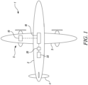
- an aircraft 1 is shown.
- the aircraft is of conventional configuration, having a fuselage 2, wings 3, tail 4 and a pair of propulsion systems 5.
- One of the propulsion systems 5 is shown in figure detail in figure 2 .
- Each propulsion system is provided with electrical energy from an energy storage system and / or a generator 20, which may be driven by a prime mover such as a gas turbine engine 22.
- FIG. 2 shows the propulsion system 5 schematically.
- the propulsion system 5 comprises an electrical machine in the form of an electric motor 28 configured to drive a propulsor in the form of a ducted fan 12 via a fan shaft 14.
- the motor 28 is fed with cooling fluid such as air or liquid coolant via cooling air duct 16, which is provided with pressurised cooling flow from the fan 12.
- the fan 12 is housed within a nacelle 24.
- the motor 28 is of a conventional type, comprising a permanent magnet electric machine, though other types of electric machines could utilise the disclosed cooling arrangement, such as induction machines and brushed machines.
- FIG. 3 shows the motor 28 in more detail.
- the motor 28 comprises a motor housing 30 which houses motor components.
- the motor housing 30 provides structural support for motor components, and is mounted to structural components of the propulsion system. Additionally, the housing 30 is generally fluid tight, save for openings where coolant ducts and electrical connections are provided.
- the motor comprises a rotor 32 which is coupled to the fan shaft 14, and is surrounded by a stator 34, provided radially outward of the rotor 32.
- the rotor 32 is configured to rotate about an axis X.
- the stator 34 comprises electrical windings 36, which can be energised to produce a rotating magnetic field.
- the electrical windings 36 comprise end windings 37, which are provided at axially forward and aft ends of the stator winding 36. This rotating magnetic field interacts with a magnetic field of the rotor 29, to cause rotation when acting as a motor.
- the windings are wound round a stator core 38, which typically comprises a plurality of laminations made of steel or similar ferromagnetic material.
- the motor housing 30 forms a stator housing, which contains the stator 34, including the windings 36 and core 38.
- a drive plate 31 is provided at an axial end, through which an axle (not shown) extends, for providing motive power.
- the stator housing 30 is penetrated by a coolant inlet duct 40, and a coolant outlet duct 42.
- the coolant inlet duct 40 communicates with an inlet chamber in the form of a coolant manifold 44 provided within the stator housing 30.
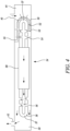
- the coolant inlet manifold 48 comprises a space defined by the inner walls of the stator housing 30 and by a baffle 50.
- the baffle 50 is positioned between the stator end windings 37 and the housing 30, and thereby controls fluid flow between the coolant inlet manifold 48 and stator end windings 37.
- the baffle 50 is shown in further detail in figure 5 , and is in the form of a ring or toroid which extends around the end windings 37 of the stator.
- the baffle 50 has a curved profile, which is curved to approximately match the curvature of the end windings 37, is spaced from the end windings 37 in use, and has an open end at an axially extending inward side to accept the end windings 37.
- seals 53, 55 are provided to seal between the baffle 50 and housing 30.
- the baffle 50 further comprises a plurality of apertures 52, which extend through the baffle 50 between the inlet manifold 44 and the stator end windings 37.
- the baffle apertures are distributed about the whole circumference of the baffle ring, and various apertures preferably extend radially inwardly and outwardly, as well as axially, in a direction generally toward the end windings 37.
- the apertures 37 may be shaped to define a convergent nozzle, with the apertures converging in the direction of the end windings 37.
- the baffle 50 is formed by Additive Layer Manufacture (ALM) such as Direct Layer Deposition (DLD) to allow for complex nozzle geometries, which may direct coolant flow in desired directions at desired velocities and flow rates.
- a further plurality of apertures 54 are provided within the stator windings 36.
- the stator core 38 comprises a hollow portion, through which coolant can flow. Similarly, at the other axial end, further apertures 56 are provided in the stator windings 36, which lead to an outlet manifold 58, which in turn communicates with the coolant outlet 42.
- a sleeve 33 is provided at each end, to confine the coolant within the stator, and provides a seal between the stator and rotor.
- a coolant passageway is therefore defined by the inlet 40, baffle apertures 52, end winding apertures 52, stator core 38, aperture 56, outlet manifold 58 and outlet 42.
- coolant fluid in this case air, though liquid coolants such as water and glycol could also be used
- coolant entering the inlet manifold is held back by the baffle 50.
- the apertures 52 in the baffle 50 act to restrict the flow of coolant, whilst also accelerating the coolant and acting as nozzles, thereby directing coolant to impinge upon the stator end windings.
- the maximum number of holes and the diameter of the holes could be adjusted to provide optimum cooling.
- this increased coolant effectiveness is believed to result from the increased local flow velocity at the end winding surface caused by the apertures acting as nozzles, resulting in an increased heat transfer coefficient.
- the high-velocity coolant jets create a thing boundary layer of coolant over the windings, thus increasing the surface area in contact with the high-velocity coolant, and reducing hot-spots.
- Figure 6 shows a first alternative cooling arrangement for an electric machine in the form of a motor 128.
- the motor 128 is similar to the motor 28, having a rotor 132 and stator 134 comprising a core 138 and stator winding 136 provided within a housing 130.
- the arrangement of cooling inlets, outlets and baffles differs from that of the motor 28.
- first and second inlets 140a, 140b are provided, which communicate respectively with first and second outlets 142a, 142b.
- Each inlet 140a, 140b is provided at a respective axial end of the stator housing 130, and feeds into a respective inlet manifold 148a, 148b.
- Each inlet 140a, 140b is separated from its respective outlet 142a, 142b by a respective baffle 150a, 150b.
- the baffles 150a, 150b are similar to the baffle 50 of the first embodiment, having apertures (not shown) extending therethrough, to provide fluid communication between the respective inlets 140a, 140b and outlets 142a, 142b.
- Each baffle 150a, 150b is positioned adjacent a respective end winding 137a, 137b of the stator winding 136.
- coolant such as air or a liquid coolant
- in use coolant flows from respective inlets 140a, 140b into respective inlet manifolds 148a, 148b, through the apertures provided in the respective baffles 150a, 150b, whereupon the coolant flow impinges on the end windings 137a, 137b.
- Spent coolant is then directed out of respective outlets 142a, 142b.
- each end winding is actively cooled by impingement cooling, while the stator core 138 is not actively cooled by the coolant.
- Such a design may be appropriate where room can be provided for a coolant system at each end, and where temperatures of the uncooled stator core are acceptable in use.
- stator winding In order to prevent leakage between the two ends of the stator, full vacuum impregnation of the stator winding may be utilised, to ensure that no fluid passage is provided through the central portion of the stator winding.
- Figure 7 shows a second alternative cooling arrangement for an electric machine in the form of a motor 228.
- the motor 228 is again similar to the motors 28, 128, having a rotor 332 and stator 334 comprising a core 238 and stator winding 236 provided within a housing 230.
- the housing 230 comprises a drive plate 231 through which an axle extends.
- the arrangement of cooling inlets, outlets and baffles differs from that of the motors 28, 128.
- first and second inlets 240a, 240b are provided, which communicate respectively with first and second outlets 242a, 242b via respective baffles 250a, 250b.
- Each inlet 240a, 240b is provided at a respective axial end of the stator housing 230, and feeds into a respective inlet manifold 248a, 248b.
- the first inlet 240a is separated from its outlet 242a by a baffle 250a.
- the baffle 150a is similar to the baffles 50, 150 of the first and second embodiments, having apertures (not shown) extending therethrough, to provide fluid communication between the inlets 240a, and outlet 242a.
- the baffle 150a is positioned adjacent a first end winding 237a, of the stator winding 236, and extends around radially inner and outer sides of the end winding 237a.
- the second end winding 237b is provided with a baffle 250b having a different form.
- the baffle 250b forms part of the housing, and is provided at the end of the motor opposite the drive plate 231. Again, apertures 252 are provided through the baffle 250b, which extend in a generally axial direction, toward the end winding 237b. Consequently, impingement cooling is provided in this location, though the impingement may be less effective, since coolant is provided in an axial direction only. As such, either reduced cooling effectiveness is achieved, or increased coolant flow is required.
- flow through the stator core 238 may be provided by providing a second inlet 240b and first outlet 242a having a larger diameter relative to the first inlet 240a and second outlet 242b. Coolant flow may be permitted through channels (not shown) in the stator core 238, resulting in the airflow shown in figure 7 .
- Such an arrangement allows for increased space in the stator housing for winding terminations on the non-drive end of the stator housing 230.
- coolant such as air or a liquid coolant
- in use coolant flows from respective inlets 140a, 140b into respective inlet manifolds 148a, 148b, through the apertures provided in the respective baffles 150a, 150b, whereupon the coolant flow impinges on the end windings 137a, 137b.
- Spent coolant is then directed out of respective outlets 142a, 142b.
- the electric machine may comprise a generator, such as the generator 20 driven by the gas turbine engine 22 of a propulsion system.
- the electric machine may be utilised in non-aerospace applications, or for non-propulsive purposes in an aircraft. Examples include fuel and hydraulic pumps.
Landscapes
- Engineering & Computer Science (AREA)
- Power Engineering (AREA)
- Aviation & Aerospace Engineering (AREA)
- Chemical & Material Sciences (AREA)
- Combustion & Propulsion (AREA)
- Mechanical Engineering (AREA)
- Motor Or Generator Cooling System (AREA)
Abstract
Description
- The present disclosure concerns an electric machine suitable for an aircraft propulsion system, and a propulsion system comprising the electric machine.
- Electric machines can take the form of either generators, which convert mechanical torque to electrical energy, or motors, which convert electrical energy to mechanical torque. In either case, it is desirable to provide electric machines having a high power density, i.e. a high power per unit mass or volume. Such high power densities are particularly useful for applications such as aircraft propulsion systems, where both high power and low mass are desirable.
- Such high power densities can result in cooling challenges. In particular, it can be difficult to provide sufficient coolant flow at a sufficiently low temperature to maintain low electric machine temperatures during use, where the electric machine has a physically small volume. Such problems are exacerbated where the coolant comprises a gaseous coolant such as air, which has a low heat transfer coefficient.
- The present disclosure seeks to provide an electric machine having improved cooling.
- According to a first aspect there is provided an electric machine comprising:
- a stator winding located within a stator housing;
- the stator housing comprising an inlet chamber configured to communicate with a supply of coolant, and an outlet;
- the stator housing comprising a baffle configured to separate the stator winding and outlet from the inlet chamber; wherein
- the baffle comprises at least one aperture therethrough configured to supply an impingement flow of coolant to the stator winding.
- Advantageously, for a given coolant flow and inlet temperature, the effectiveness of the coolant in reducing stator winding temperatures is increased relative to conventional flood cooling, since the apertures within the baffle direct coolant at higher velocity toward the stator windings, which increases cooling effectiveness.
- The baffle may be provided adjacent an end winding of the stator. The baffle may at least partly surround generally opposite sides of the end winding. The baffle may comprise at least one aperture adjacent each side of the end winding.
- The stator winding may comprise first and second end windings at opposite sides of the stator housing.
- The baffle may be provided adjacent the first end winding, and the outlet may be provided adjacent the second end winding. The stator winding may define a channel through which coolant is configured to flow from the baffle to the outlet.
- Alternatively, a first outlet may be provided adjacent a first end winding separated from a first inlet by a first baffle, and a second outlet may be provided at a second end winding separated from a second inlet by a second baffle. The second baffle may comprise an end plate of the stator housing. Advantageously, interference between the baffle and winding terminations is avoided.
- The first inlet may be configured to provide a lower coolant flow rate in use relative to the second inlet. The first outlet may be configured to pass a higher coolant flow rate in use relative to the second outlet. The winding may define a channel configured to communicate between the second inlet and first outlet. Consequently, coolant may flow in use from both the first and second inlets and through the stator winding to the first outlet, thereby preventing hot-spots in the winding.
- The or each aperture in the or each baffle may comprise a nozzle configured to accelerate flow through the aperture.
- According to a second aspect of the invention there is provided an aircraft propulsion system comprising an electric machine in accordance with the first aspect.
- The electric machine may comprise one or both of a generator and a motor.
- The propulsion system may comprise an internal combustion engine, and the generator may be configured to be driven by the internal combustion engine.
- Alternatively or additionally, the propulsion system may comprise a propulsor, and the motor may be configured to drive the propulsor.
- The skilled person will appreciate that except where mutually exclusive, a feature described in relation to any one of the above aspects may be applied mutatis mutandis to any other aspect. Furthermore except where mutually exclusive any feature described herein may be applied to any aspect and/or combined with any other feature described herein.
- Embodiments will now be described by way of example only, with reference to the Figures, in which:
-
Figure 1 is a plan view of an aircraft comprising an electric propulsion system; -
Figure 2 is a cross-sectional side view of the propulsion system of the aircraft offigure 1 ; -
Figure 3 is a cross-sectional view of an electric machine in the form of a motor for use in the propulsion system offigure 2 ; -
Figure 4 is a cross-sectional side view of part of a stator and stator housing of the electric machine offigure 3 ; -
Figure 5 is a perspective side view of a baffle of the electric machine offigure 3 ; -
Figure 6 is a cross-sectional side view of part of a first alternative stator for the electric machine offigure 3 ; and -
Figure 7 is a cross-sectional side view of part of a second alternative stator for the electric machine offigure 3 . - With reference to
Figure 1 , an aircraft 1 is shown. The aircraft is of conventional configuration, having afuselage 2,wings 3,tail 4 and a pair ofpropulsion systems 5. One of thepropulsion systems 5 is shown in figure detail infigure 2 . Each propulsion system is provided with electrical energy from an energy storage system and / or agenerator 20, which may be driven by a prime mover such as agas turbine engine 22. -
Figure 2 shows thepropulsion system 5 schematically. Thepropulsion system 5 comprises an electrical machine in the form of anelectric motor 28 configured to drive a propulsor in the form of aducted fan 12 via afan shaft 14. Themotor 28 is fed with cooling fluid such as air or liquid coolant viacooling air duct 16, which is provided with pressurised cooling flow from thefan 12. Thefan 12 is housed within anacelle 24. - The
motor 28 is of a conventional type, comprising a permanent magnet electric machine, though other types of electric machines could utilise the disclosed cooling arrangement, such as induction machines and brushed machines. -
Figure 3 shows themotor 28 in more detail. Themotor 28 comprises amotor housing 30 which houses motor components. Themotor housing 30 provides structural support for motor components, and is mounted to structural components of the propulsion system. Additionally, thehousing 30 is generally fluid tight, save for openings where coolant ducts and electrical connections are provided. - The motor comprises a
rotor 32 which is coupled to thefan shaft 14, and is surrounded by astator 34, provided radially outward of therotor 32. Therotor 32 is configured to rotate about an axis X. Thestator 34 compriseselectrical windings 36, which can be energised to produce a rotating magnetic field. Theelectrical windings 36 compriseend windings 37, which are provided at axially forward and aft ends of the stator winding 36. This rotating magnetic field interacts with a magnetic field of the rotor 29, to cause rotation when acting as a motor. The windings are wound round astator core 38, which typically comprises a plurality of laminations made of steel or similar ferromagnetic material. - The
motor housing 30 forms a stator housing, which contains thestator 34, including thewindings 36 andcore 38. Adrive plate 31 is provided at an axial end, through which an axle (not shown) extends, for providing motive power. Thestator housing 30 is penetrated by acoolant inlet duct 40, and acoolant outlet duct 42. Thecoolant inlet duct 40 communicates with an inlet chamber in the form of acoolant manifold 44 provided within thestator housing 30. Thecoolant inlet manifold 48 comprises a space defined by the inner walls of thestator housing 30 and by abaffle 50. Thebaffle 50 is positioned between thestator end windings 37 and thehousing 30, and thereby controls fluid flow between thecoolant inlet manifold 48 and stator end windings 37. - Part of the
stator 34 is shown in further detail infigure 4 . Thebaffle 50 is shown in further detail infigure 5 , and is in the form of a ring or toroid which extends around theend windings 37 of the stator. Thebaffle 50 has a curved profile, which is curved to approximately match the curvature of theend windings 37, is spaced from theend windings 37 in use, and has an open end at an axially extending inward side to accept theend windings 37. Referring again tofigure 4 , seals 53, 55 are provided to seal between thebaffle 50 andhousing 30. Thebaffle 50 further comprises a plurality ofapertures 52, which extend through thebaffle 50 between theinlet manifold 44 and the stator end windings 37. The baffle apertures are distributed about the whole circumference of the baffle ring, and various apertures preferably extend radially inwardly and outwardly, as well as axially, in a direction generally toward theend windings 37. In some cases, theapertures 37 may be shaped to define a convergent nozzle, with the apertures converging in the direction of theend windings 37. In one embodiment, thebaffle 50 is formed by Additive Layer Manufacture (ALM) such as Direct Layer Deposition (DLD) to allow for complex nozzle geometries, which may direct coolant flow in desired directions at desired velocities and flow rates. A further plurality ofapertures 54 are provided within thestator windings 36. Thestator core 38 comprises a hollow portion, through which coolant can flow. Similarly, at the other axial end,further apertures 56 are provided in thestator windings 36, which lead to anoutlet manifold 58, which in turn communicates with thecoolant outlet 42. Asleeve 33 is provided at each end, to confine the coolant within the stator, and provides a seal between the stator and rotor. - A coolant passageway is therefore defined by the
inlet 40,baffle apertures 52,end winding apertures 52,stator core 38,aperture 56,outlet manifold 58 andoutlet 42. In use therefore, coolant fluid (in this case air, though liquid coolants such as water and glycol could also be used) flows through theinlet 40,baffle apertures 52,end winding apertures 52,stator core 38,aperture 56,outlet manifold 58 and out theoutlet 42, as shown by the arrows infigure 4 , picking up heat and cooling thestator windings 36 andstator core 38 in use. - It has however been found that particular attention needs to be paid to cooling of the stator end windings 37. These experience high heat loads and temperatures in use, which can lead to failure. The present arrangement provides improved cooling of this area in particular.
- As shown by the arrows in
figure 4 , coolant entering the inlet manifold is held back by thebaffle 50. Theapertures 52 in thebaffle 50 act to restrict the flow of coolant, whilst also accelerating the coolant and acting as nozzles, thereby directing coolant to impinge upon the stator end windings. - This direct impingement flow toward the
stator end windings 37 has been found to greatly increase cooling effectiveness. Computer Fluid Dynamics (CFD) simulations were performed on a simulated motor. In the simulation, 5 litres / minute of coolant was supplied, which resulted in end winding temperatures of 108°C. In comparison simulations, with the same geometry, coolant temperatures and cooling flows, but with the baffle removed, hot spots of 131 °C were found at the end windings. Consequently, the impingement cooling provided by the baffle provided a 23°C reduction in end winding temperatures. By raising the coolant flow rate to 19 litres / minute, a maximum winding temperature of 97°C could be achieved - a 34 °C reduction. As will be understood, for various applications, the maximum number of holes and the diameter of the holes could be adjusted to provide optimum cooling. Without wishing to be limited by theory, this increased coolant effectiveness is believed to result from the increased local flow velocity at the end winding surface caused by the apertures acting as nozzles, resulting in an increased heat transfer coefficient. Additionally, the high-velocity coolant jets create a thing boundary layer of coolant over the windings, thus increasing the surface area in contact with the high-velocity coolant, and reducing hot-spots. -
Figure 6 shows a first alternative cooling arrangement for an electric machine in the form of amotor 128. Themotor 128 is similar to themotor 28, having arotor 132 andstator 134 comprising acore 138 and stator winding 136 provided within ahousing 130. However, the arrangement of cooling inlets, outlets and baffles differs from that of themotor 28. - In the
motor 128, first andsecond inlets inlet stator housing 130, and feeds into arespective inlet manifold 148a, 148b. Eachinlet respective baffle baffles baffle 50 of the first embodiment, having apertures (not shown) extending therethrough, to provide fluid communication between therespective inlets baffle - Consequently, in use, coolant (such as air or a liquid coolant) flows from
respective inlets respective inlet manifolds 148a, 148b, through the apertures provided in therespective baffles end windings 137a, 137b. Spent coolant is then directed out of respective outlets 142a, 142b. - Consequently, each end winding is actively cooled by impingement cooling, while the
stator core 138 is not actively cooled by the coolant. Such a design may be appropriate where room can be provided for a coolant system at each end, and where temperatures of the uncooled stator core are acceptable in use. - In order to prevent leakage between the two ends of the stator, full vacuum impregnation of the stator winding may be utilised, to ensure that no fluid passage is provided through the central portion of the stator winding.
-
Figure 7 shows a second alternative cooling arrangement for an electric machine in the form of amotor 228. - The
motor 228 is again similar to themotors core 238 and stator winding 236 provided within ahousing 230. Thehousing 230 comprises adrive plate 231 through which an axle extends. However, the arrangement of cooling inlets, outlets and baffles differs from that of themotors - In the
motor 228, first andsecond inlets 240a, 240b are provided, which communicate respectively with first andsecond outlets 242a, 242b viarespective baffles inlet 240a, 240b is provided at a respective axial end of thestator housing 230, and feeds into arespective inlet manifold 248a, 248b. Thefirst inlet 240a is separated from its outlet 242a by abaffle 250a. Thebaffle 150a is similar to thebaffles 50, 150 of the first and second embodiments, having apertures (not shown) extending therethrough, to provide fluid communication between theinlets 240a, and outlet 242a. Thebaffle 150a is positioned adjacent a first end winding 237a, of the stator winding 236, and extends around radially inner and outer sides of the end winding 237a. - The second end winding 237b is provided with a
baffle 250b having a different form. Thebaffle 250b forms part of the housing, and is provided at the end of the motor opposite thedrive plate 231. Again,apertures 252 are provided through thebaffle 250b, which extend in a generally axial direction, toward the end winding 237b. Consequently, impingement cooling is provided in this location, though the impingement may be less effective, since coolant is provided in an axial direction only. As such, either reduced cooling effectiveness is achieved, or increased coolant flow is required. - In one embodiment, flow through the
stator core 238 may be provided by providing a second inlet 240b and first outlet 242a having a larger diameter relative to thefirst inlet 240a andsecond outlet 242b. Coolant flow may be permitted through channels (not shown) in thestator core 238, resulting in the airflow shown infigure 7 . - Such an arrangement allows for increased space in the stator housing for winding terminations on the non-drive end of the
stator housing 230. - Consequently, in use, coolant (such as air or a liquid coolant) flows from
respective inlets respective inlet manifolds 148a, 148b, through the apertures provided in therespective baffles end windings 137a, 137b. Spent coolant is then directed out of respective outlets 142a, 142b. - It will be understood that the invention is not limited to the embodiments above-described and various modifications and improvements can be made without departing from the concepts described herein. For example, the electric machine may comprise a generator, such as the
generator 20 driven by thegas turbine engine 22 of a propulsion system. The electric machine may be utilised in non-aerospace applications, or for non-propulsive purposes in an aircraft. Examples include fuel and hydraulic pumps. - Except where mutually exclusive, any of the features may be employed separately or in combination with any other features and the disclosure extends to and includes all combinations and sub-combinations of one or more features described herein.
Claims (13)
- An electric machine (28) comprising:a stator winding (34) located within a stator housing (31);the stator housing comprising an inlet chamber (48) configured to communicate with a supply of coolant, and an outlet (42);the stator housing comprising a baffle (50) configured to separate the stator winding and outlet from the inlet chamber; whereinthe baffle comprises at least one aperture (52) therethrough configured to supply an impingement flow of coolant to the stator winding.
- An electric machine according to claim 1, wherein the baffle is provided adjacent an end winding (37) of the stator.
- An electric machine according to claim 2, wherein the baffle at least partly surrounds generally opposite sides of the end winding.
- An electric machine according to claim 2 or claim 3, wherein the stator winding defines a channel through which coolant is configured to flow from the baffle to the outlet.
- An electric machine according to any of the preceding claims, wherein a first outlet (142a) is provided adjacent a first end winding (137a) separated from a first inlet (140a) by a first baffle (150a), and a second outlet (142b) is provided at second end winding (137b) separated from a second inlet (104b) by a second baffle (150b).
- An electric machine according to claim 5, wherein the first inlet is configured to provide a lower coolant flow rate in use relative to the second inlet.
- An electric machine according to claim 5 or claim 6, wherein the first outlet is configured to pass a higher coolant flow rate in use relative to the second outlet.
- An electric machine according to any of claims 5 to 7, wherein the winding (134) defines a channel configured to communicate between the second inlet and first outlet.
- An electric machine according to any of the preceding claims, wherein the or each aperture in the or each baffle comprises a nozzle (52) configured to accelerate flow through the aperture.
- An aircraft propulsion system (5) comprising an electric machine (28) in accordance with any of the preceding claims.
- An aircraft propulsion system according to claim 10, wherein the electric machine comprises one or both of a generator (20) and a motor (28).
- An aircraft propulsion system according to claim 10 or claim 11, wherein the propulsion system comprises an internal combustion engine (22), and the generator (20) is configured to be driven by the internal combustion engine.
- An aircraft propulsion system according to any of claims 10 to 12, wherein the propulsion system comprises a propulsor (12), and the motor (28) is configured to drive the propulsor.
Applications Claiming Priority (1)
| Application Number | Priority Date | Filing Date | Title |
|---|---|---|---|
| GBGB2116498.3A GB202116498D0 (en) | 2021-11-16 | 2021-11-16 | Electric machine |
Publications (2)
| Publication Number | Publication Date |
|---|---|
| EP4181360A1 true EP4181360A1 (en) | 2023-05-17 |
| EP4181360B1 EP4181360B1 (en) | 2025-05-07 |
Family
ID=79163686
Family Applications (1)
| Application Number | Title | Priority Date | Filing Date |
|---|---|---|---|
| EP22201783.2A Active EP4181360B1 (en) | 2021-11-16 | 2022-10-17 | Electric machine |
Country Status (3)
| Country | Link |
|---|---|
| US (1) | US20230150683A1 (en) |
| EP (1) | EP4181360B1 (en) |
| GB (1) | GB202116498D0 (en) |
Families Citing this family (2)
| Publication number | Priority date | Publication date | Assignee | Title |
|---|---|---|---|---|
| US12531453B2 (en) * | 2022-06-27 | 2026-01-20 | Garrett Transportation I Inc. | E-machine with a cooling system including manifold member for spray of stator cooling fluid |
| US20250119004A1 (en) * | 2023-10-06 | 2025-04-10 | Rolls-Royce North American Technologies, Inc. | Electric machine cooling |
Citations (6)
| Publication number | Priority date | Publication date | Assignee | Title |
|---|---|---|---|---|
| JPS56110770U (en) * | 1980-01-24 | 1981-08-27 | ||
| JP2000041361A (en) * | 1998-07-22 | 2000-02-08 | Toshiba Corp | Rotating electric machine |
| JP2001078391A (en) * | 1999-09-08 | 2001-03-23 | Toshiba Corp | Rotating electric machine |
| EP2242164A1 (en) * | 2008-08-22 | 2010-10-20 | Aisin AW Co., Ltd. | Rotating electric machine |
| WO2020120611A1 (en) * | 2018-12-12 | 2020-06-18 | Thyssenkrupp Ag | Cooling channel for a winding overhang of a stator, and stator comprising a cooling channel of this type |
| US10756598B2 (en) * | 2017-10-02 | 2020-08-25 | Ge Aviation Systems Llc | Method and apparatus for cooling a rotor assembly |
-
2021
- 2021-11-16 GB GBGB2116498.3A patent/GB202116498D0/en not_active Ceased
-
2022
- 2022-10-17 EP EP22201783.2A patent/EP4181360B1/en active Active
- 2022-10-31 US US18/051,113 patent/US20230150683A1/en not_active Abandoned
Patent Citations (6)
| Publication number | Priority date | Publication date | Assignee | Title |
|---|---|---|---|---|
| JPS56110770U (en) * | 1980-01-24 | 1981-08-27 | ||
| JP2000041361A (en) * | 1998-07-22 | 2000-02-08 | Toshiba Corp | Rotating electric machine |
| JP2001078391A (en) * | 1999-09-08 | 2001-03-23 | Toshiba Corp | Rotating electric machine |
| EP2242164A1 (en) * | 2008-08-22 | 2010-10-20 | Aisin AW Co., Ltd. | Rotating electric machine |
| US10756598B2 (en) * | 2017-10-02 | 2020-08-25 | Ge Aviation Systems Llc | Method and apparatus for cooling a rotor assembly |
| WO2020120611A1 (en) * | 2018-12-12 | 2020-06-18 | Thyssenkrupp Ag | Cooling channel for a winding overhang of a stator, and stator comprising a cooling channel of this type |
Also Published As
| Publication number | Publication date |
|---|---|
| GB202116498D0 (en) | 2021-12-29 |
| EP4181360B1 (en) | 2025-05-07 |
| US20230150683A1 (en) | 2023-05-18 |
Similar Documents
| Publication | Publication Date | Title |
|---|---|---|
| EP3780344B1 (en) | Stator assembly, electrical motor, wind power generator set and method for cooling stator assembly | |
| US20230150683A1 (en) | Electric machine | |
| EP3422533B1 (en) | Electrical machine apparatus | |
| WO2021089188A1 (en) | Axial flux motor with cooling jacket | |
| EP3764523B1 (en) | Electric machine with integrated cooling system | |
| EP4253729B1 (en) | THERMAL INSULATION SYSTEM FOR A MICROTURBINE GENERATOR | |
| US11346247B2 (en) | Turbine engine including a heat exchanger formed in a platform | |
| US6392326B1 (en) | Flow-through spaceblocks with deflectors and method for increased electric generator endwinding cooling | |
| WO2023199066A1 (en) | Electric propulsion systems | |
| CN117318395A (en) | A motor with a self-circulating oil-immersed cooling structure | |
| US11255215B2 (en) | Gas turbine engine with microchannel cooled electric device | |
| US6417586B1 (en) | Gas cooled endwindings for dynamoelectric machine rotor and endwinding cool method | |
| EP4253761B1 (en) | High speed turbo-alternator with integrated cooling fan | |
| EP4183996B1 (en) | Cooling system for tail cone mounted generator | |
| US7342345B2 (en) | Paddled rotor spaceblocks | |
| CN119966155A (en) | Marine motor cooling system | |
| US20100237723A1 (en) | System and method for thermal management in electrical machines | |
| JP2024142037A (en) | Housing for rotating electrical machine and manufacturing method thereof | |
| CN118783684A (en) | Electric Motors, Powertrains and Vehicles | |
| CN221328758U (en) | Motor | |
| US20110221288A1 (en) | System and method for cooling in electric machines | |
| CN113708550A (en) | Electric machine | |
| US12510029B1 (en) | Electric generator in turbine engine | |
| EP4518107A1 (en) | Motor radiator | |
| JP2024142042A (en) | Housing for rotating electrical machine and manufacturing method thereof |
Legal Events
| Date | Code | Title | Description |
|---|---|---|---|
| PUAI | Public reference made under article 153(3) epc to a published international application that has entered the european phase |
Free format text: ORIGINAL CODE: 0009012 |
|
| STAA | Information on the status of an ep patent application or granted ep patent |
Free format text: STATUS: THE APPLICATION HAS BEEN PUBLISHED |
|
| AK | Designated contracting states |
Kind code of ref document: A1 Designated state(s): AL AT BE BG CH CY CZ DE DK EE ES FI FR GB GR HR HU IE IS IT LI LT LU LV MC ME MK MT NL NO PL PT RO RS SE SI SK SM TR |
|
| STAA | Information on the status of an ep patent application or granted ep patent |
Free format text: STATUS: REQUEST FOR EXAMINATION WAS MADE |
|
| 17P | Request for examination filed |
Effective date: 20230831 |
|
| RBV | Designated contracting states (corrected) |
Designated state(s): AL AT BE BG CH CY CZ DE DK EE ES FI FR GB GR HR HU IE IS IT LI LT LU LV MC ME MK MT NL NO PL PT RO RS SE SI SK SM TR |
|
| GRAP | Despatch of communication of intention to grant a patent |
Free format text: ORIGINAL CODE: EPIDOSNIGR1 |
|
| STAA | Information on the status of an ep patent application or granted ep patent |
Free format text: STATUS: GRANT OF PATENT IS INTENDED |
|
| RIC1 | Information provided on ipc code assigned before grant |
Ipc: H02K 3/24 20060101ALI20250220BHEP Ipc: H02K 9/197 20060101AFI20250220BHEP |
|
| GRAS | Grant fee paid |
Free format text: ORIGINAL CODE: EPIDOSNIGR3 |
|
| GRAA | (expected) grant |
Free format text: ORIGINAL CODE: 0009210 |
|
| STAA | Information on the status of an ep patent application or granted ep patent |
Free format text: STATUS: THE PATENT HAS BEEN GRANTED |
|
| INTG | Intention to grant announced |
Effective date: 20250305 |
|
| P01 | Opt-out of the competence of the unified patent court (upc) registered |
Free format text: CASE NUMBER: APP_12558/2025 Effective date: 20250313 |
|
| AK | Designated contracting states |
Kind code of ref document: B1 Designated state(s): AL AT BE BG CH CY CZ DE DK EE ES FI FR GB GR HR HU IE IS IT LI LT LU LV MC ME MK MT NL NO PL PT RO RS SE SI SK SM TR |
|
| REG | Reference to a national code |
Ref country code: GB Ref legal event code: FG4D |
|
| REG | Reference to a national code |
Ref country code: CH Ref legal event code: EP |
|
| REG | Reference to a national code |
Ref country code: DE Ref legal event code: R096 Ref document number: 602022014178 Country of ref document: DE |
|
| REG | Reference to a national code |
Ref country code: IE Ref legal event code: FG4D |
|
| REG | Reference to a national code |
Ref country code: NL Ref legal event code: MP Effective date: 20250507 |
|
| PG25 | Lapsed in a contracting state [announced via postgrant information from national office to epo] |
Ref country code: PT Free format text: LAPSE BECAUSE OF FAILURE TO SUBMIT A TRANSLATION OF THE DESCRIPTION OR TO PAY THE FEE WITHIN THE PRESCRIBED TIME-LIMIT Effective date: 20250908 Ref country code: ES Free format text: LAPSE BECAUSE OF FAILURE TO SUBMIT A TRANSLATION OF THE DESCRIPTION OR TO PAY THE FEE WITHIN THE PRESCRIBED TIME-LIMIT Effective date: 20250507 Ref country code: FI Free format text: LAPSE BECAUSE OF FAILURE TO SUBMIT A TRANSLATION OF THE DESCRIPTION OR TO PAY THE FEE WITHIN THE PRESCRIBED TIME-LIMIT Effective date: 20250507 |
|
| REG | Reference to a national code |
Ref country code: LT Ref legal event code: MG9D |
|
| PG25 | Lapsed in a contracting state [announced via postgrant information from national office to epo] |
Ref country code: NO Free format text: LAPSE BECAUSE OF FAILURE TO SUBMIT A TRANSLATION OF THE DESCRIPTION OR TO PAY THE FEE WITHIN THE PRESCRIBED TIME-LIMIT Effective date: 20250807 Ref country code: GR Free format text: LAPSE BECAUSE OF FAILURE TO SUBMIT A TRANSLATION OF THE DESCRIPTION OR TO PAY THE FEE WITHIN THE PRESCRIBED TIME-LIMIT Effective date: 20250808 |
|
| PG25 | Lapsed in a contracting state [announced via postgrant information from national office to epo] |
Ref country code: NL Free format text: LAPSE BECAUSE OF FAILURE TO SUBMIT A TRANSLATION OF THE DESCRIPTION OR TO PAY THE FEE WITHIN THE PRESCRIBED TIME-LIMIT Effective date: 20250507 Ref country code: PL Free format text: LAPSE BECAUSE OF FAILURE TO SUBMIT A TRANSLATION OF THE DESCRIPTION OR TO PAY THE FEE WITHIN THE PRESCRIBED TIME-LIMIT Effective date: 20250507 |
|
| REG | Reference to a national code |
Ref country code: AT Ref legal event code: MK05 Ref document number: 1793601 Country of ref document: AT Kind code of ref document: T Effective date: 20250507 |
|
| PG25 | Lapsed in a contracting state [announced via postgrant information from national office to epo] |
Ref country code: BG Free format text: LAPSE BECAUSE OF FAILURE TO SUBMIT A TRANSLATION OF THE DESCRIPTION OR TO PAY THE FEE WITHIN THE PRESCRIBED TIME-LIMIT Effective date: 20250507 |
|
| PG25 | Lapsed in a contracting state [announced via postgrant information from national office to epo] |
Ref country code: HR Free format text: LAPSE BECAUSE OF FAILURE TO SUBMIT A TRANSLATION OF THE DESCRIPTION OR TO PAY THE FEE WITHIN THE PRESCRIBED TIME-LIMIT Effective date: 20250507 |
|
| PG25 | Lapsed in a contracting state [announced via postgrant information from national office to epo] |
Ref country code: AT Free format text: LAPSE BECAUSE OF FAILURE TO SUBMIT A TRANSLATION OF THE DESCRIPTION OR TO PAY THE FEE WITHIN THE PRESCRIBED TIME-LIMIT Effective date: 20250507 |
|
| PG25 | Lapsed in a contracting state [announced via postgrant information from national office to epo] |
Ref country code: RS Free format text: LAPSE BECAUSE OF FAILURE TO SUBMIT A TRANSLATION OF THE DESCRIPTION OR TO PAY THE FEE WITHIN THE PRESCRIBED TIME-LIMIT Effective date: 20250807 |
|
| PG25 | Lapsed in a contracting state [announced via postgrant information from national office to epo] |
Ref country code: IS Free format text: LAPSE BECAUSE OF FAILURE TO SUBMIT A TRANSLATION OF THE DESCRIPTION OR TO PAY THE FEE WITHIN THE PRESCRIBED TIME-LIMIT Effective date: 20250907 |
|
| PG25 | Lapsed in a contracting state [announced via postgrant information from national office to epo] |
Ref country code: LV Free format text: LAPSE BECAUSE OF FAILURE TO SUBMIT A TRANSLATION OF THE DESCRIPTION OR TO PAY THE FEE WITHIN THE PRESCRIBED TIME-LIMIT Effective date: 20250507 |
|
| PGFP | Annual fee paid to national office [announced via postgrant information from national office to epo] |
Ref country code: DE Payment date: 20251028 Year of fee payment: 4 |
|
| PG25 | Lapsed in a contracting state [announced via postgrant information from national office to epo] |
Ref country code: SM Free format text: LAPSE BECAUSE OF FAILURE TO SUBMIT A TRANSLATION OF THE DESCRIPTION OR TO PAY THE FEE WITHIN THE PRESCRIBED TIME-LIMIT Effective date: 20250507 Ref country code: DK Free format text: LAPSE BECAUSE OF FAILURE TO SUBMIT A TRANSLATION OF THE DESCRIPTION OR TO PAY THE FEE WITHIN THE PRESCRIBED TIME-LIMIT Effective date: 20250507 |
|
| PGFP | Annual fee paid to national office [announced via postgrant information from national office to epo] |
Ref country code: FR Payment date: 20251027 Year of fee payment: 4 |
|
| PG25 | Lapsed in a contracting state [announced via postgrant information from national office to epo] |
Ref country code: CZ Free format text: LAPSE BECAUSE OF FAILURE TO SUBMIT A TRANSLATION OF THE DESCRIPTION OR TO PAY THE FEE WITHIN THE PRESCRIBED TIME-LIMIT Effective date: 20250507 |
|
| PG25 | Lapsed in a contracting state [announced via postgrant information from national office to epo] |
Ref country code: EE Free format text: LAPSE BECAUSE OF FAILURE TO SUBMIT A TRANSLATION OF THE DESCRIPTION OR TO PAY THE FEE WITHIN THE PRESCRIBED TIME-LIMIT Effective date: 20250507 |
|
| PG25 | Lapsed in a contracting state [announced via postgrant information from national office to epo] |
Ref country code: SK Free format text: LAPSE BECAUSE OF FAILURE TO SUBMIT A TRANSLATION OF THE DESCRIPTION OR TO PAY THE FEE WITHIN THE PRESCRIBED TIME-LIMIT Effective date: 20250507 |
|
| PG25 | Lapsed in a contracting state [announced via postgrant information from national office to epo] |
Ref country code: IT Free format text: LAPSE BECAUSE OF FAILURE TO SUBMIT A TRANSLATION OF THE DESCRIPTION OR TO PAY THE FEE WITHIN THE PRESCRIBED TIME-LIMIT Effective date: 20250507 |
|
| REG | Reference to a national code |
Ref country code: DE Ref legal event code: R097 Ref document number: 602022014178 Country of ref document: DE |
|
| PG25 | Lapsed in a contracting state [announced via postgrant information from national office to epo] |
Ref country code: RO Free format text: LAPSE BECAUSE OF FAILURE TO SUBMIT A TRANSLATION OF THE DESCRIPTION OR TO PAY THE FEE WITHIN THE PRESCRIBED TIME-LIMIT Effective date: 20250507 |
|
| PLBE | No opposition filed within time limit |
Free format text: ORIGINAL CODE: 0009261 |
|
| STAA | Information on the status of an ep patent application or granted ep patent |
Free format text: STATUS: NO OPPOSITION FILED WITHIN TIME LIMIT |
|
| REG | Reference to a national code |
Ref country code: CH Ref legal event code: L10 Free format text: ST27 STATUS EVENT CODE: U-0-0-L10-L00 (AS PROVIDED BY THE NATIONAL OFFICE) Effective date: 20260318 |
|
| 26N | No opposition filed |
Effective date: 20260210 |