EP4181310A1 - Secondary battery - Google Patents
Secondary battery Download PDFInfo
- Publication number
- EP4181310A1 EP4181310A1 EP22195835.8A EP22195835A EP4181310A1 EP 4181310 A1 EP4181310 A1 EP 4181310A1 EP 22195835 A EP22195835 A EP 22195835A EP 4181310 A1 EP4181310 A1 EP 4181310A1
- Authority
- EP
- European Patent Office
- Prior art keywords
- secondary battery
- layer
- cutout parts
- active material
- cathode
- Prior art date
- Legal status (The legal status is an assumption and is not a legal conclusion. Google has not performed a legal analysis and makes no representation as to the accuracy of the status listed.)
- Pending
Links
Images


Classifications
-
- H—ELECTRICITY
- H01—ELECTRIC ELEMENTS
- H01M—PROCESSES OR MEANS, e.g. BATTERIES, FOR THE DIRECT CONVERSION OF CHEMICAL ENERGY INTO ELECTRICAL ENERGY
- H01M10/00—Secondary cells; Manufacture thereof
- H01M10/04—Construction or manufacture in general
-
- H—ELECTRICITY
- H01—ELECTRIC ELEMENTS
- H01M—PROCESSES OR MEANS, e.g. BATTERIES, FOR THE DIRECT CONVERSION OF CHEMICAL ENERGY INTO ELECTRICAL ENERGY
- H01M50/00—Constructional details or processes of manufacture of the non-active parts of electrochemical cells other than fuel cells, e.g. hybrid cells
- H01M50/10—Primary casings; Jackets or wrappings
- H01M50/172—Arrangements of electric connectors penetrating the casing
- H01M50/174—Arrangements of electric connectors penetrating the casing adapted for the shape of the cells
- H01M50/176—Arrangements of electric connectors penetrating the casing adapted for the shape of the cells for prismatic or rectangular cells
-
- H—ELECTRICITY
- H01—ELECTRIC ELEMENTS
- H01M—PROCESSES OR MEANS, e.g. BATTERIES, FOR THE DIRECT CONVERSION OF CHEMICAL ENERGY INTO ELECTRICAL ENERGY
- H01M50/00—Constructional details or processes of manufacture of the non-active parts of electrochemical cells other than fuel cells, e.g. hybrid cells
- H01M50/50—Current conducting connections for cells or batteries
- H01M50/543—Terminals
- H01M50/547—Terminals characterised by the disposition of the terminals on the cells
-
- H—ELECTRICITY
- H01—ELECTRIC ELEMENTS
- H01M—PROCESSES OR MEANS, e.g. BATTERIES, FOR THE DIRECT CONVERSION OF CHEMICAL ENERGY INTO ELECTRICAL ENERGY
- H01M50/00—Constructional details or processes of manufacture of the non-active parts of electrochemical cells other than fuel cells, e.g. hybrid cells
- H01M50/10—Primary casings; Jackets or wrappings
- H01M50/102—Primary casings; Jackets or wrappings characterised by their shape or physical structure
- H01M50/103—Primary casings; Jackets or wrappings characterised by their shape or physical structure prismatic or rectangular
-
- H—ELECTRICITY
- H01—ELECTRIC ELEMENTS
- H01M—PROCESSES OR MEANS, e.g. BATTERIES, FOR THE DIRECT CONVERSION OF CHEMICAL ENERGY INTO ELECTRICAL ENERGY
- H01M50/00—Constructional details or processes of manufacture of the non-active parts of electrochemical cells other than fuel cells, e.g. hybrid cells
- H01M50/10—Primary casings; Jackets or wrappings
- H01M50/116—Primary casings; Jackets or wrappings characterised by the material
- H01M50/121—Organic material
-
- H—ELECTRICITY
- H01—ELECTRIC ELEMENTS
- H01M—PROCESSES OR MEANS, e.g. BATTERIES, FOR THE DIRECT CONVERSION OF CHEMICAL ENERGY INTO ELECTRICAL ENERGY
- H01M50/00—Constructional details or processes of manufacture of the non-active parts of electrochemical cells other than fuel cells, e.g. hybrid cells
- H01M50/50—Current conducting connections for cells or batteries
- H01M50/531—Electrode connections inside a battery casing
- H01M50/533—Electrode connections inside a battery casing characterised by the shape of the leads or tabs
-
- H—ELECTRICITY
- H01—ELECTRIC ELEMENTS
- H01M—PROCESSES OR MEANS, e.g. BATTERIES, FOR THE DIRECT CONVERSION OF CHEMICAL ENERGY INTO ELECTRICAL ENERGY
- H01M50/00—Constructional details or processes of manufacture of the non-active parts of electrochemical cells other than fuel cells, e.g. hybrid cells
- H01M50/50—Current conducting connections for cells or batteries
- H01M50/543—Terminals
- H01M50/547—Terminals characterised by the disposition of the terminals on the cells
- H01M50/548—Terminals characterised by the disposition of the terminals on the cells on opposite sides of the cell
-
- H—ELECTRICITY
- H01—ELECTRIC ELEMENTS
- H01M—PROCESSES OR MEANS, e.g. BATTERIES, FOR THE DIRECT CONVERSION OF CHEMICAL ENERGY INTO ELECTRICAL ENERGY
- H01M50/00—Constructional details or processes of manufacture of the non-active parts of electrochemical cells other than fuel cells, e.g. hybrid cells
- H01M50/50—Current conducting connections for cells or batteries
- H01M50/543—Terminals
- H01M50/552—Terminals characterised by their shape
- H01M50/553—Terminals adapted for prismatic, pouch or rectangular cells
-
- H—ELECTRICITY
- H01—ELECTRIC ELEMENTS
- H01M—PROCESSES OR MEANS, e.g. BATTERIES, FOR THE DIRECT CONVERSION OF CHEMICAL ENERGY INTO ELECTRICAL ENERGY
- H01M50/00—Constructional details or processes of manufacture of the non-active parts of electrochemical cells other than fuel cells, e.g. hybrid cells
- H01M50/50—Current conducting connections for cells or batteries
- H01M50/572—Means for preventing undesired use or discharge
- H01M50/584—Means for preventing undesired use or discharge for preventing incorrect connections inside or outside the batteries
- H01M50/586—Means for preventing undesired use or discharge for preventing incorrect connections inside or outside the batteries inside the batteries, e.g. incorrect connections of electrodes
-
- H—ELECTRICITY
- H01—ELECTRIC ELEMENTS
- H01M—PROCESSES OR MEANS, e.g. BATTERIES, FOR THE DIRECT CONVERSION OF CHEMICAL ENERGY INTO ELECTRICAL ENERGY
- H01M50/00—Constructional details or processes of manufacture of the non-active parts of electrochemical cells other than fuel cells, e.g. hybrid cells
- H01M50/50—Current conducting connections for cells or batteries
- H01M50/572—Means for preventing undesired use or discharge
- H01M50/584—Means for preventing undesired use or discharge for preventing incorrect connections inside or outside the batteries
- H01M50/59—Means for preventing undesired use or discharge for preventing incorrect connections inside or outside the batteries characterised by the protection means
- H01M50/595—Tapes
-
- Y—GENERAL TAGGING OF NEW TECHNOLOGICAL DEVELOPMENTS; GENERAL TAGGING OF CROSS-SECTIONAL TECHNOLOGIES SPANNING OVER SEVERAL SECTIONS OF THE IPC; TECHNICAL SUBJECTS COVERED BY FORMER USPC CROSS-REFERENCE ART COLLECTIONS [XRACs] AND DIGESTS
- Y02—TECHNOLOGIES OR APPLICATIONS FOR MITIGATION OR ADAPTATION AGAINST CLIMATE CHANGE
- Y02E—REDUCTION OF GREENHOUSE GAS [GHG] EMISSIONS, RELATED TO ENERGY GENERATION, TRANSMISSION OR DISTRIBUTION
- Y02E60/00—Enabling technologies; Technologies with a potential or indirect contribution to GHG emissions mitigation
- Y02E60/10—Energy storage using batteries
Definitions
- the present disclosure relates to a secondary battery.
- Patent Literature 1 discloses a secondary battery comprising a rectangular exterior body in a plan view, an electrode body housed in the exterior body, and a cathode terminal and an anode terminal that are at one or respective two sides of the exterior body, wherein the respective two sides are opposite to each other.
- Patent Literature 1 JP 2005-56815 A
- an object of the present disclosure is to provide a secondary battery having a structure that can reduce a space therefor.
- a secondary battery comprising: exterior bodies that look a quadrilateral as a whole in a plan view; an electrode body that is housed in the exterior bodies; cutout parts at respective two sides among sides of the quadrilateral, the two sides being opposite to each other; a cathode terminal disposed in one of the cutout parts; and an anode terminal disposed in another one of the cutout parts.
- the two cutout parts may be provided at respective corners of the quadrilateral, the corners being opposite to each other.
- the electrode body which is housed in the exterior bodies, may be also provided with cutout parts, at least part of each of the cutout parts a resin layer being placed.
- the secondary battery according to the present disclosure can suppress generation of a wasted space due to protrusion of electrode terminals, and can reduce a space for the secondary battery.
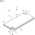
- Figs. 1 to 5 illustrate a secondary battery 10 according to one embodiment.
- Fig. 1 is an external perspective view
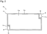
- Fig. 2 is a plan view (looking in the direction pointed by the arrow II in Fig. 1 )
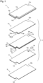
- Fig. 3 is an exploded perspective view
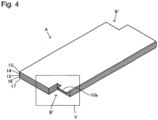
- Fig. 4 is an external perspective view showing an electrode body A that is a layered body to be placed inside exterior bodies of the secondary battery 10
- Fig. 5 is an enlarged view focusing on a portion where a cutout part B' is formed in Fig. 4 .
- the secondary battery 10 is a quadrilateral as a whole in a plan view (from the viewpoint of Fig. 2 ) which is provided with cutout parts B at respective two corners that are opposite to each other.
- a quadrilateral as a whole means that: it can be acknowledged that a quadrilateral would be formed if no cutout parts B were cut out; and the quadrilateral is not necessary to be a quadrilateral in a strict sense, but may have roughness with some necessary member and has a form that can be regarded as a quadrilateral as a whole.
- the secondary battery 10 has a first exterior body 11, a second exterior body 12, a cathode current collector layer 13, a cathode active material layer 14, a separator layer 15, an anode active material layer 16, an anode current collector layer 17, a cathode terminal 18, and an anode terminal 19.
- the secondary battery 10 is formed by layering these layers.
- the secondary battery 10 is also provided with resin layers 20 (refer to Fig. 5 ). The structure of each member and the relationship thereof will be hereinafter described.
- a layered body portion formed by the cathode current collector layer 13, the cathode active material layer 14, the separator layer 15, the anode active material layer 16, and the anode current collector layer 17 may be expressed as "electrode body A".
- the first exterior body 11 and the second exterior body 12 are each a sheet member of an exterior material.
- the first exterior body 11 and the second exterior body 12 are each formed by joining circumferential end portions thereof as including the electrode body A, a part of the cathode terminal 18, and a part of the anode terminal 19 therebetween. Therefore, these exterior bodies form a bag.
- the electrode body A is included and sealed in these exterior bodies.
- the first exterior body 11 has a depressed part 11a including an opening in one face thereof (the opening is invisible in Fig. 3 because being in the face on the bottom side in the sheet, and thus, entering a blind spot).
- the electrode body A is housed inside this depressed part 11a.
- the circumferential edge of the depressed part 11a is provided with a joined part 11b, so that the joined part 11b protrudes from the edge.
- This joined part 11b and a circumferential end portion of a face of the second exterior body 12 are joined to each other.
- the first exterior body 11 is a quadrilateral as a whole in a plan view, and in order to form the cutout parts B, is provided with cutout parts 11c at respective two corners that are opposite to each other.
- the second exterior body 12 is in the form of a sheet, and is a quadrilateral member as a whole in a plan view. In order to form the cutout parts B, the second exterior body 12 is also provided with cutout parts 12c at respective two corners that are opposite to each other.
- the first exterior body 11 and the second exterior body 12 are each formed of a laminate sheet.
- the laminate sheet is a sheet having a metal layer and a sealant layer.
- a metal etc. used for the laminate sheet include aluminum and stainless steel.
- the material used for the sealant layer include polypropylene, polyethylene, polystyrene and polyvinyl chloride which are thermoplastic resins.
- the way of joining the first exterior body 11 and the second exterior body 12 to each other, that is, joining the laminate sheets is not particularly limited, but any known way may be used therefor. Specific examples of the way include: ways of welding (e.g., hot plate welding, ultrasonic welding, vibration welding, and laser welding) the sealant layers of the laminate sheets to each other; and adhering with an adhesive.
- ways of welding e.g., hot plate welding, ultrasonic welding, vibration welding, and laser welding
- the cathode current collector layer 13 is a layer included in the electrode body A, and is layered on the cathode active material layer 14 to collect a current from the cathode active material layer 14.
- the cathode current collector layer 13 is in the form of quadrilateral foil as a whole in a plan view, and in order to form the cutout parts B, is provided with cutout parts 13c at respective two corners that are opposite to each other.
- a cathode tab 13a to which the cathode terminal 18 is to be connected is arranged inside one of the two cutout parts 13c of the cathode current collector layer 13.
- the cathode tab 13a is a part to electrically connect the cathode current collector layer 13 and the cathode terminal 18.
- Examples of the material constituting the cathode current collector layer 13 include stainless steel, aluminum, nickel, iron, titanium, and carbon.
- the cathode active material layer 14 is a layer included in the electrode body A.
- the cathode current collector layer 13 is layered on one face of the cathode active material layer 14; and the separator layer 15 is layered on the other face of the cathode active material layer 14.
- the cathode active material layer 14 is in the form of a quadrilateral sheet as a whole in a plan view, and in order to form the cutout parts B, is provided with cutout parts 14c at respective two corners that are opposite to each other.
- the cathode active material layer 14 is a layer containing a cathode active material, and may further contain at least one of a solid electrolyte material, a conductive material, and a binder, if necessary.
- any known active material may be used as the cathode active material.
- the cathode active material include cobalt-based (such as LiCoO 2 ), nickel-based (such as LiNiO 2 ), manganese-based (such as LiMn 2 O 4 and Li 2 Mn 2 O 3 ), iron phosphate-based (such as LiFePO 4 and Li 2 FeP 2 O 7 ), NCA-based (such as a compound of nickel, cobalt and aluminum), and NMC-based (such as a compound of nickel, manganese and cobalt) active materials, and a more specific example thereof is LiNi 1/3 Co 1/3 Mn 1/3 O 2 .
- the surface of the cathode active material may be coated with an oxide layer such as a lithium niobate layer, a lithium titanate layer and a lithium phosphate layer.
- the solid electrolyte is preferably an inorganic solid electrolyte because the inorganic solid electrolyte has high ionic conductivity and is excellent in heat resistance, compared with the organic polymer electrolyte.
- examples of the inorganic solid electrolyte include sulfide solid electrolytes and oxide solid electrolytes.
- Examples of sulfide solid electrolyte materials having Li-ion conductivity include Li 2 S-P 2 S 5 , Li 2 S-P 2 S 5 -LiI, Li 2 S-P 2 S 5 -Li 2 O, Li 2 S-P 2 S 5 -Li 2 O-LiI, Li 2 S-SiS 2 , Li 2 S-SiS 2 -LiI, Li 2 S-SiS 2 -LiBr, Li 2 S-SiS 2 -LiCl, Li 2 S-SiS 2 -B 2 S 3 -LiI, Li 2 S-SiS 2 -P 2 S 5 -LiI, Li 2 S-B 2 S 3 , Li 2 S-P 2 S 5 -Z m S n (m and n are positive numbers, and Z is any of Ge, Zn and Ga), Li 2 S-GeS 2 , Li 2 S-SiS 2 -Li 3 PO 4 and Li 2 S-SiS 2
- oxide solid electrolyte materials having Li-ion conductivity include compounds having a NASICON-type structure.
- compounds having a NASICON-type structure include compounds represented by the general formula Li 1+x Al x Ge 2-x (PO 4 ) 3 (0 ⁇ x ⁇ 2) (LAGP), and compounds represented by the general formula Li 1+x Al x Ti 2-x (PO 4 ) 3 (0 ⁇ x ⁇ 2) (LATP).
- Other examples of the oxide solid electrolyte materials include LiLaTiO (such as Li 0.34 La 0.51 TiO 3 ), LiPON (such as Li 2.9 PO 3.3 N 0.46 ) and LiLaZrO (such as Li 7 La 3 Zr 2 O 12 ).
- the binder is not particularly limited as long as being chemically and electrically stable.
- the binder include fluorine-based binders such as polyvinylidene fluoride (PVDF) and polytetrafluoroethylene (PTFE), rubber-based binders such as styrenebutadiene rubber (SBR), olefinic binders such as polypropylene (PP) and polyethylene (PE), and cellulose-based binders such as carboxymethyl cellulose (CMC).
- a carbon material such as acetylene black (AB), Ketjen black, or carbon fiber, or a metal material such as nickel, aluminum and stainless steel may be used.
- the content of each component in the cathode active material layer 14 may be the same as a conventional one.
- the cathode active material layer 14 preferably has a thickness of, for example, 0.1 ⁇ m to 1 mm, and more preferably has a thickness of 1 ⁇ m to 150 ⁇ m.
- the separator layer (solid electrolyte layer) 15 is a layer formed by containing a solid electrolyte material as being placed between the cathode active material layer 14 and the anode active material layer 16.
- the separator layer 15 contains at least a solid electrolyte material.
- the solid electrolyte material may be considered in the same manner as that described for the cathode active material layer 14.
- the separator layer 15 is a layer included in the electrode body A, is in the form of a quadrilateral sheet as a whole in a plan view, and in order to form the cutout parts B, is provided with cutout parts 15c at respective two corners that are opposite to each other.
- the anode active material layer 16 is a layer included in the electrode body A and containing at least an anode active material.
- the anode active material layer 16 may contain a binder, a conductive material, and a solid electrolyte material, if necessary.
- the binder, the conductive material, and the solid electrolyte material may be considered in the same manner as those for the cathode active material layer 14.
- the anode active material is not particularly limited.
- examples of the anode active material include carbon materials such as graphite and hard carbon, various oxides such as lithium titanate, Si and Si alloys, and metallic lithium and lithium alloys.
- the anode active material layer 16 is in the form of a quadrilateral sheet as a whole in a plan view.
- the separator layer 15 is layered on one face of the anode active material layer 16; and the anode current collector layer 17 is layered on the other face of the anode active material layer 16.
- the anode active material layer 16 is provided with cutout parts 16c at respective two corners that are opposite to each other.
- the content of each component in the anode active material layer 16 may be the same as a conventional one.
- the anode active material layer 16 preferably has a thickness of, for example, 0.1 ⁇ m to 1 mm, and more preferably has a thickness of 1 ⁇ m to 150 ⁇ m.
- the anode current collector layer 17 is a layer included in the electrode body A, and is layered on the anode active material layer 16 to collect a current from the anode active material layer 16.
- the anode current collector layer 17 is in the form of quadrilateral foil as a whole in a plan view, and in order to form the cutout parts B, is provided with cutout parts 17c at respective two corners that are opposite to each other.
- An anode tab 17a to which the anode terminal 19 is to be connected is arranged inside one of the two cutout parts 17c of the anode current collector layer 17.
- the anode tab 17a is a part to electrically connect the anode current collector layer 17 and the anode terminal 19.
- the anode tab 17a is arranged in the cutout part B on the opposite side of the cutout part B where the cathode tab 13a of the cathode current collector layer 13 is arranged, among the two cutout parts 17c.
- Examples of the material constituting the anode current collector layer 17 include stainless steel, copper, nickel, and carbon.
- the cathode terminal 18 and the anode terminal 19 are electroconductive members, and are to be terminals for electrically connecting respective electrodes to the outside.
- one end of the cathode terminal 18 is electrically connected to the cathode tab 13a, and the other end thereof penetrates a joined portion of the first exterior body 11 and the second exterior body 12 to be exposed to the outside. At this time, the cathode terminal 18 is placed in one of the two cutout parts B of the secondary battery 10.
- One end of the anode terminal 19 is electrically connected to the anode tab 17a, and the other end thereof penetrates a joined portion of the first exterior body 11 and the second exterior body 12 to be exposed to the outside. At this time, the anode terminal 19 is placed in the other one of the two cutout parts B of the secondary battery 10, where the cathode terminal 18 is not placed.
- the resin layer 20 is a resin layer layered on a face that appeared in each of the cutout parts B' formed by layering the cutout parts (13c, 14c, 15c, 16c, 17c) provided in the respective layers in the electrode body A.
- This resin layer 20 can prevent short-circuiting.
- an electrical insulating material may be applied as the material constituting the resin layer 20, and examples thereof include urethane acrylate resins, epoxy resins, and olefin resins. Any of various curable resins or any of various thermoplastic resins can be used.
- the curable resin may be a thermosetting resin, a photocurable resin (e.g., UV curable resin) or an electron beam curable resin.
- the resin layer may be formed from one or plural resin(s).
- the area the placed resin layer 20 has is not particularly limited.
- the resin layer 20 may be placed only on part of the face that appeared in the cutout part B', or may be placed on the entire face, as long as short-circuiting can be prevented.
- the resin layer 20 like this can be formed by applying, onto the face, a resin before curing, and curing the resin by an appropriate way.
- Fig. 6 is an external perspective view of a secondary battery 30 according to another embodiment.
- the secondary battery 30 in the form of a quadrilateral as a whole in a plan view is different from the secondary battery 10 in that the cutout parts B are not provided at corners, but at the respective centers of sides that are opposite to each other.
- Such a secondary battery also exerts effect as the secondary battery according to the present disclosure.
- a stack of secondary batteries 100 can be obtained by stacking the plural secondary batteries 10 each as unit cells.
- the secondary batteries can be connected in series by: disposing the secondary batteries 10, so that the electrodes are different from each other between the facing electrode terminals (cathode and anode terminals) of every two secondary batteries 10 that are adjacent to each other in the stacking direction; and connecting the facing terminals to each other.
- the secondary batteries can be connected in parallel by: disposing the secondary batteries 10, so that the electrodes of the facing terminals of every two secondary batteries 10 that are adjacent to each other are the same; and connecting the facing terminals to each other.
- the secondary battery 30 may be also considered in the same manner.
- the secondary battery according to the present disclosure can suppress generation of a wasted space because, as well understood from, for example, Fig. 2 , all or most of the cathode terminal 18 and the anode terminal 19 can be housed inside the cutout parts B, and thus, the secondary battery has no protruding portions of the terminals only.
- the protruding electrode terminals make it difficult to use the spaces indicated by the dotted lines, and as a result, the spaces adjacent to the electrode terminals are also for the electrode terminals substantially.
- the shape and size of each of the cutout parts B are not particularly limited, but are preferably made, so that all or most of the cathode terminal and the anode terminal can be housed inside the cutout parts B in a plan view.
- the secondary battery according to the present disclosure can suppress generation of a wasted space, can reduce the proportion of the secondary battery in a device, and can realize an efficient arrangement in structure.
- Arranging the two cutout parts at such positions that these cutout parts are symmetrical in a plan view can suppress an unstable reaction (deviation) of the electrodes.
- the above effect is exerted even when only exterior bodies are provided with cutout parts corresponding to the cutout parts B but an electrode body is not provided therewith.
- providing the electrode body A to be housed in the exterior bodies with the cutout parts B' corresponding to the cutout parts B as well makes the shapes inside the exterior bodies and the outer shape of the electrode body similar, which can make the proportion of the electrode body in the space inside the exterior bodies larger, can reduce a wasted space, and can make the space efficiently utilized. Therefore, providing the electrode body with the cutout parts B' can further suppress generation of a wasted space in the secondary battery, can reduce the proportion of the secondary battery in a device, and can realize an efficient arrangement in structure.
Landscapes
- Chemical & Material Sciences (AREA)
- Chemical Kinetics & Catalysis (AREA)
- Electrochemistry (AREA)
- General Chemical & Material Sciences (AREA)
- Engineering & Computer Science (AREA)
- Manufacturing & Machinery (AREA)
- Sealing Battery Cases Or Jackets (AREA)
- Connection Of Batteries Or Terminals (AREA)
- Secondary Cells (AREA)
Abstract
Provided is a secondary battery having a structure that can reduce a space for the secondary battery. The secondary battery includes: exterior bodies that look a quadrilateral as a whole in a plan view; an electrode body that is housed in the exterior bodies; cutout parts at respective two sides among the sides of the quadrilateral, the two sides being opposite to each other; a cathode terminal disposed in one of the cutout parts; and an anode terminal disposed in another one of the cutout parts.
Description
- The present disclosure relates to a secondary battery.
- Patent Literature 1 discloses a secondary battery comprising a rectangular exterior body in a plan view, an electrode body housed in the exterior body, and a cathode terminal and an anode terminal that are at one or respective two sides of the exterior body, wherein the respective two sides are opposite to each other.
- Patent Literature 1:
JP 2005-56815 A - When plural secondary batteries are stacked and each terminal thereof is connected, the connection is that the terminals protruding from a rectangular exterior body in a plan view are connected to each other as in Patent Literature 1 to form a wasted space. Thus, improvement in structural efficiency (reduction of the space for the secondary batteries) is desired.
- In view of the above problem, an object of the present disclosure is to provide a secondary battery having a structure that can reduce a space therefor.
- As one measure to solve the above problem, the present application discloses a secondary battery comprising: exterior bodies that look a quadrilateral as a whole in a plan view; an electrode body that is housed in the exterior bodies; cutout parts at respective two sides among sides of the quadrilateral, the two sides being opposite to each other; a cathode terminal disposed in one of the cutout parts; and an anode terminal disposed in another one of the cutout parts.
- The two cutout parts may be provided at respective corners of the quadrilateral, the corners being opposite to each other.
- The electrode body, which is housed in the exterior bodies, may be also provided with cutout parts, at least part of each of the cutout parts a resin layer being placed. Advantageous Effects
- The secondary battery according to the present disclosure can suppress generation of a wasted space due to protrusion of electrode terminals, and can reduce a space for the secondary battery.
-
-
Fig. 1 is an external perspective view of asecondary battery 10; -
Fig. 2 is a plan view of thesecondary battery 10; -
Fig. 3 is an exploded perspective view of thesecondary battery 10; -
Fig. 4 is an external perspective view of an electrode body A; -
Fig. 5 focuses on a portion of a cutout part B' inFig. 4 ; -
Fig. 6 is an external perspective view of asecondary battery 30; -
Fig. 7 is an external perspective view of abattery stack 100; and -
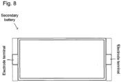
Fig. 8 illustrates a conventional secondary battery. - The present disclosure will be hereinafter described using embodiments. Here, the embodiments to be described are examples. The present disclosure is not limited to these embodiments.
-
Figs. 1 to 5 illustrate asecondary battery 10 according to one embodiment.Fig. 1 is an external perspective view,Fig. 2 is a plan view (looking in the direction pointed by the arrow II inFig. 1 ),Fig. 3 is an exploded perspective view,Fig. 4 is an external perspective view showing an electrode body A that is a layered body to be placed inside exterior bodies of thesecondary battery 10, andFig. 5 is an enlarged view focusing on a portion where a cutout part B' is formed inFig. 4 . - As seen from
Figs. 1 to 5 , thesecondary battery 10 according to the present embodiment is a quadrilateral as a whole in a plan view (from the viewpoint ofFig. 2 ) which is provided with cutout parts B at respective two corners that are opposite to each other. Here, "a quadrilateral as a whole" means that: it can be acknowledged that a quadrilateral would be formed if no cutout parts B were cut out; and the quadrilateral is not necessary to be a quadrilateral in a strict sense, but may have roughness with some necessary member and has a form that can be regarded as a quadrilateral as a whole. - The
secondary battery 10 has a firstexterior body 11, a secondexterior body 12, a cathodecurrent collector layer 13, a cathodeactive material layer 14, aseparator layer 15, an anodeactive material layer 16, an anodecurrent collector layer 17, acathode terminal 18, and ananode terminal 19. Thesecondary battery 10 is formed by layering these layers. Thesecondary battery 10 is also provided with resin layers 20 (refer toFig. 5 ). The structure of each member and the relationship thereof will be hereinafter described. - Here, a layered body portion formed by the cathode
current collector layer 13, the cathodeactive material layer 14, theseparator layer 15, the anodeactive material layer 16, and the anodecurrent collector layer 17 may be expressed as "electrode body A". - The first
exterior body 11 and the secondexterior body 12 are each a sheet member of an exterior material. The firstexterior body 11 and the secondexterior body 12 are each formed by joining circumferential end portions thereof as including the electrode body A, a part of thecathode terminal 18, and a part of theanode terminal 19 therebetween. Therefore, these exterior bodies form a bag. The electrode body A is included and sealed in these exterior bodies. - The first
exterior body 11 has adepressed part 11a including an opening in one face thereof (the opening is invisible inFig. 3 because being in the face on the bottom side in the sheet, and thus, entering a blind spot). The electrode body A is housed inside thisdepressed part 11a. The circumferential edge of thedepressed part 11a is provided with a joinedpart 11b, so that the joinedpart 11b protrudes from the edge. This joinedpart 11b and a circumferential end portion of a face of the secondexterior body 12 are joined to each other. - In the present embodiment, the first
exterior body 11 is a quadrilateral as a whole in a plan view, and in order to form the cutout parts B, is provided withcutout parts 11c at respective two corners that are opposite to each other. - The second
exterior body 12 is in the form of a sheet, and is a quadrilateral member as a whole in a plan view. In order to form the cutout parts B, the secondexterior body 12 is also provided withcutout parts 12c at respective two corners that are opposite to each other. - As described above, the circumferential end portion of a face among the faces of the second
exterior body 12 which faces the firstexterior body 11 is superposed on and joined to the joinedpart 11b of the firstexterior body 11. - In the present embodiment, the first
exterior body 11 and the secondexterior body 12 are each formed of a laminate sheet. Here, the laminate sheet is a sheet having a metal layer and a sealant layer. Examples of a metal etc. used for the laminate sheet include aluminum and stainless steel. Examples of the material used for the sealant layer include polypropylene, polyethylene, polystyrene and polyvinyl chloride which are thermoplastic resins. - The way of joining the first
exterior body 11 and the secondexterior body 12 to each other, that is, joining the laminate sheets is not particularly limited, but any known way may be used therefor. Specific examples of the way include: ways of welding (e.g., hot plate welding, ultrasonic welding, vibration welding, and laser welding) the sealant layers of the laminate sheets to each other; and adhering with an adhesive. - The cathode
current collector layer 13 is a layer included in the electrode body A, and is layered on the cathodeactive material layer 14 to collect a current from the cathodeactive material layer 14. The cathodecurrent collector layer 13 is in the form of quadrilateral foil as a whole in a plan view, and in order to form the cutout parts B, is provided withcutout parts 13c at respective two corners that are opposite to each other. - A
cathode tab 13a to which thecathode terminal 18 is to be connected is arranged inside one of the twocutout parts 13c of the cathodecurrent collector layer 13. Thecathode tab 13a is a part to electrically connect the cathodecurrent collector layer 13 and thecathode terminal 18. - Examples of the material constituting the cathode
current collector layer 13 include stainless steel, aluminum, nickel, iron, titanium, and carbon. - The cathode
active material layer 14 is a layer included in the electrode body A. The cathodecurrent collector layer 13 is layered on one face of the cathodeactive material layer 14; and theseparator layer 15 is layered on the other face of the cathodeactive material layer 14. The cathodeactive material layer 14 is in the form of a quadrilateral sheet as a whole in a plan view, and in order to form the cutout parts B, is provided withcutout parts 14c at respective two corners that are opposite to each other. - The cathode
active material layer 14 is a layer containing a cathode active material, and may further contain at least one of a solid electrolyte material, a conductive material, and a binder, if necessary. - Any known active material may be used as the cathode active material. Examples of the cathode active material include cobalt-based (such as LiCoO2), nickel-based (such as LiNiO2), manganese-based (such as LiMn2O4 and Li2Mn2O3), iron phosphate-based (such as LiFePO4 and Li2FeP2O7), NCA-based (such as a compound of nickel, cobalt and aluminum), and NMC-based (such as a compound of nickel, manganese and cobalt) active materials, and a more specific example thereof is LiNi1/3Co1/3Mn1/3O2.
- The surface of the cathode active material may be coated with an oxide layer such as a lithium niobate layer, a lithium titanate layer and a lithium phosphate layer.
- The solid electrolyte is preferably an inorganic solid electrolyte because the inorganic solid electrolyte has high ionic conductivity and is excellent in heat resistance, compared with the organic polymer electrolyte. Examples of the inorganic solid electrolyte include sulfide solid electrolytes and oxide solid electrolytes.
- Examples of sulfide solid electrolyte materials having Li-ion conductivity include Li2S-P2S5, Li2S-P2S5-LiI, Li2S-P2S5-Li2O, Li2S-P2S5-Li2O-LiI, Li2S-SiS2, Li2S-SiS2-LiI, Li2S-SiS2-LiBr, Li2S-SiS2-LiCl, Li2S-SiS2-B2S3-LiI, Li2S-SiS2-P2S5-LiI, Li2S-B2S3, Li2S-P2S5-ZmSn (m and n are positive numbers, and Z is any of Ge, Zn and Ga), Li2S-GeS2, Li2S-SiS2-Li3PO4 and Li2S-SiS2-LixMOy (x and y are positive numbers, and M is any of P, Si, Ge, B, Al, Ga and In). The expression "Li2S-P2S5" means any sulfide solid electrolyte material made with a raw material composition containing Li2S and P2S5. The same is applied to the other expressions.
- Examples of oxide solid electrolyte materials having Li-ion conductivity include compounds having a NASICON-type structure. Examples of compounds having a NASICON-type structure include compounds represented by the general formula Li1+xAlxGe2-x(PO4)3 (0 ≤ x ≤ 2) (LAGP), and compounds represented by the general formula Li1+xAlxTi2-x(PO4)3 (0 ≤ x ≤ 2) (LATP). Other examples of the oxide solid electrolyte materials include LiLaTiO (such as Li0.34La0.51TiO3), LiPON (such as Li2.9PO3.3N0.46) and LiLaZrO (such as Li7La3Zr2O12).
- The binder is not particularly limited as long as being chemically and electrically stable. Examples of the binder include fluorine-based binders such as polyvinylidene fluoride (PVDF) and polytetrafluoroethylene (PTFE), rubber-based binders such as styrenebutadiene rubber (SBR), olefinic binders such as polypropylene (PP) and polyethylene (PE), and cellulose-based binders such as carboxymethyl cellulose (CMC).
- As the conductive material, a carbon material such as acetylene black (AB), Ketjen black, or carbon fiber, or a metal material such as nickel, aluminum and stainless steel may be used.
- The content of each component in the cathode
active material layer 14 may be the same as a conventional one. The cathodeactive material layer 14 preferably has a thickness of, for example, 0.1 µm to 1 mm, and more preferably has a thickness of 1 µm to 150 µm. - The separator layer (solid electrolyte layer) 15 is a layer formed by containing a solid electrolyte material as being placed between the cathode
active material layer 14 and the anodeactive material layer 16. Theseparator layer 15 contains at least a solid electrolyte material. The solid electrolyte material may be considered in the same manner as that described for the cathodeactive material layer 14. - The
separator layer 15 is a layer included in the electrode body A, is in the form of a quadrilateral sheet as a whole in a plan view, and in order to form the cutout parts B, is provided withcutout parts 15c at respective two corners that are opposite to each other. - The anode
active material layer 16 is a layer included in the electrode body A and containing at least an anode active material. The anodeactive material layer 16 may contain a binder, a conductive material, and a solid electrolyte material, if necessary. The binder, the conductive material, and the solid electrolyte material may be considered in the same manner as those for the cathodeactive material layer 14. - The anode active material is not particularly limited. When a lithium ion battery is formed, examples of the anode active material include carbon materials such as graphite and hard carbon, various oxides such as lithium titanate, Si and Si alloys, and metallic lithium and lithium alloys.
- The anode
active material layer 16 is in the form of a quadrilateral sheet as a whole in a plan view. Theseparator layer 15 is layered on one face of the anodeactive material layer 16; and the anodecurrent collector layer 17 is layered on the other face of the anodeactive material layer 16. In order to form the cutout parts B, the anodeactive material layer 16 is provided withcutout parts 16c at respective two corners that are opposite to each other. - The content of each component in the anode
active material layer 16 may be the same as a conventional one. The anodeactive material layer 16 preferably has a thickness of, for example, 0.1 µm to 1 mm, and more preferably has a thickness of 1 µm to 150 µm. - The anode
current collector layer 17 is a layer included in the electrode body A, and is layered on the anodeactive material layer 16 to collect a current from the anodeactive material layer 16. The anodecurrent collector layer 17 is in the form of quadrilateral foil as a whole in a plan view, and in order to form the cutout parts B, is provided withcutout parts 17c at respective two corners that are opposite to each other. - An
anode tab 17a to which theanode terminal 19 is to be connected is arranged inside one of the twocutout parts 17c of the anodecurrent collector layer 17. Theanode tab 17a is a part to electrically connect the anodecurrent collector layer 17 and theanode terminal 19. Here, as seen fromFigs. 1 to 3 , in the electrode body A, theanode tab 17a is arranged in the cutout part B on the opposite side of the cutout part B where thecathode tab 13a of the cathodecurrent collector layer 13 is arranged, among the twocutout parts 17c. - Examples of the material constituting the anode
current collector layer 17 include stainless steel, copper, nickel, and carbon. - The
cathode terminal 18 and theanode terminal 19 are electroconductive members, and are to be terminals for electrically connecting respective electrodes to the outside. - Therefore, one end of the
cathode terminal 18 is electrically connected to thecathode tab 13a, and the other end thereof penetrates a joined portion of the firstexterior body 11 and the secondexterior body 12 to be exposed to the outside. At this time, thecathode terminal 18 is placed in one of the two cutout parts B of thesecondary battery 10. - One end of the
anode terminal 19 is electrically connected to theanode tab 17a, and the other end thereof penetrates a joined portion of the firstexterior body 11 and the secondexterior body 12 to be exposed to the outside. At this time, theanode terminal 19 is placed in the other one of the two cutout parts B of thesecondary battery 10, where thecathode terminal 18 is not placed. - As shown in
Fig. 5 , theresin layer 20 is a resin layer layered on a face that appeared in each of the cutout parts B' formed by layering the cutout parts (13c, 14c, 15c, 16c, 17c) provided in the respective layers in the electrode body A. Thisresin layer 20 can prevent short-circuiting. Accordingly, an electrical insulating material may be applied as the material constituting theresin layer 20, and examples thereof include urethane acrylate resins, epoxy resins, and olefin resins. Any of various curable resins or any of various thermoplastic resins can be used. The curable resin may be a thermosetting resin, a photocurable resin (e.g., UV curable resin) or an electron beam curable resin. The resin layer may be formed from one or plural resin(s). - The area the placed
resin layer 20 has is not particularly limited. Theresin layer 20 may be placed only on part of the face that appeared in the cutout part B', or may be placed on the entire face, as long as short-circuiting can be prevented. Theresin layer 20 like this can be formed by applying, onto the face, a resin before curing, and curing the resin by an appropriate way. -
Fig. 6 is an external perspective view of asecondary battery 30 according to another embodiment. In this embodiment, thesecondary battery 30 in the form of a quadrilateral as a whole in a plan view is different from thesecondary battery 10 in that the cutout parts B are not provided at corners, but at the respective centers of sides that are opposite to each other. Such a secondary battery also exerts effect as the secondary battery according to the present disclosure. - As shown in
Fig. 7 , a stack ofsecondary batteries 100 can be obtained by stacking the pluralsecondary batteries 10 each as unit cells. At this time, as shown inFig. 7 , the secondary batteries can be connected in series by: disposing thesecondary batteries 10, so that the electrodes are different from each other between the facing electrode terminals (cathode and anode terminals) of every twosecondary batteries 10 that are adjacent to each other in the stacking direction; and connecting the facing terminals to each other. - The secondary batteries can be connected in parallel by: disposing the
secondary batteries 10, so that the electrodes of the facing terminals of every twosecondary batteries 10 that are adjacent to each other are the same; and connecting the facing terminals to each other. - The
secondary battery 30 may be also considered in the same manner. - The secondary battery according to the present disclosure can suppress generation of a wasted space because, as well understood from, for example,
Fig. 2 , all or most of thecathode terminal 18 and theanode terminal 19 can be housed inside the cutout parts B, and thus, the secondary battery has no protruding portions of the terminals only. For example, as a conventional secondary battery shown inFig. 8 , the protruding electrode terminals make it difficult to use the spaces indicated by the dotted lines, and as a result, the spaces adjacent to the electrode terminals are also for the electrode terminals substantially. Accordingly, the shape and size of each of the cutout parts B are not particularly limited, but are preferably made, so that all or most of the cathode terminal and the anode terminal can be housed inside the cutout parts B in a plan view. - In this way, the secondary battery according to the present disclosure can suppress generation of a wasted space, can reduce the proportion of the secondary battery in a device, and can realize an efficient arrangement in structure.
- Arranging the two cutout parts at such positions that these cutout parts are symmetrical in a plan view (point-symmetrical with respect to the center of the quadrilateral in the
secondary battery 10, and line-symmetrical with respect to a center line of the quadrilateral in the secondary battery 30) can suppress an unstable reaction (deviation) of the electrodes. - In view of the external appearance of a secondary battery, the above effect is exerted even when only exterior bodies are provided with cutout parts corresponding to the cutout parts B but an electrode body is not provided therewith. However, providing the electrode body A to be housed in the exterior bodies with the cutout parts B' corresponding to the cutout parts B as well makes the shapes inside the exterior bodies and the outer shape of the electrode body similar, which can make the proportion of the electrode body in the space inside the exterior bodies larger, can reduce a wasted space, and can make the space efficiently utilized. Therefore, providing the electrode body with the cutout parts B' can further suppress generation of a wasted space in the secondary battery, can reduce the proportion of the secondary battery in a device, and can realize an efficient arrangement in structure.
-
- 10 secondary battery
- 11 exterior body (first exterior body)
- 12 exterior body (second exterior body)
- 13 cathode current collector layer
- 13a cathode tab
- 13c cutout part
- 14 cathode active material layer
- 14c cutout part
- 15 separator layer (solid electrolyte layer)
- 15c cutout part
- 16 anode active material layer
- 16c cutout part
- 17 anode current collector layer
- 17c cutout part
- 18 cathode terminal
- 19 anode terminal
- 20 resin layer
Claims (3)
- A secondary battery comprising:exterior bodies that look a quadrilateral as a whole in a plan view;an electrode body that is housed in the exterior bodies;cutout parts at respective two sides among sides of the quadrilateral, the two sides being opposite to each other;a cathode terminal disposed in one of the cutout parts; andan anode terminal disposed in another one of the cutout parts.
- The secondary battery according to claim 1, wherein
the two cutout parts are provided at respective comers of the quadrilateral, the corners being opposite to each other. - The secondary battery according to claim 1 or 2, wherein
the electrode body, which is housed in the exterior bodies, is also provided with cutout parts, at least part of each of the cutout parts a resin layer being placed.
Applications Claiming Priority (1)
| Application Number | Priority Date | Filing Date | Title |
|---|---|---|---|
| JP2021183785A JP7540423B2 (en) | 2021-11-11 | 2021-11-11 | Secondary battery |
Publications (1)
| Publication Number | Publication Date |
|---|---|
| EP4181310A1 true EP4181310A1 (en) | 2023-05-17 |
Family
ID=83355299
Family Applications (1)
| Application Number | Title | Priority Date | Filing Date |
|---|---|---|---|
| EP22195835.8A Pending EP4181310A1 (en) | 2021-11-11 | 2022-09-15 | Secondary battery |
Country Status (5)
| Country | Link |
|---|---|
| US (1) | US20230143046A1 (en) |
| EP (1) | EP4181310A1 (en) |
| JP (1) | JP7540423B2 (en) |
| KR (1) | KR102899012B1 (en) |
| CN (1) | CN116111164A (en) |
Families Citing this family (1)
| Publication number | Priority date | Publication date | Assignee | Title |
|---|---|---|---|---|
| CN118040003A (en) * | 2024-02-18 | 2024-05-14 | 宁德新能源科技有限公司 | Battery core and electric equipment |
Citations (3)
| Publication number | Priority date | Publication date | Assignee | Title |
|---|---|---|---|---|
| JP2005056815A (en) | 2003-07-22 | 2005-03-03 | Toyota Motor Corp | Secondary battery and manufacturing method thereof |
| US20140170467A1 (en) * | 2012-12-14 | 2014-06-19 | Samsung Sdi Co., Ltd. | Stack type battery |
| WO2019186932A1 (en) * | 2018-03-29 | 2019-10-03 | 株式会社 東芝 | Battery and battery pack |
Family Cites Families (4)
| Publication number | Priority date | Publication date | Assignee | Title |
|---|---|---|---|---|
| JPH117983A (en) * | 1997-06-17 | 1999-01-12 | Yuasa Corp | Solid electrolyte cell and multicellular solid electrolyte battery using the same |
| JP2012018795A (en) | 2010-07-07 | 2012-01-26 | Nec Energy Devices Ltd | Laminate-type battery and battery module |
| JP6354454B2 (en) | 2014-08-26 | 2018-07-11 | 株式会社豊田自動織機 | Power storage device |
| JP6859059B2 (en) | 2015-09-30 | 2021-04-14 | 積水化学工業株式会社 | Lithium-ion secondary battery and its manufacturing method |
-
2021
- 2021-11-11 JP JP2021183785A patent/JP7540423B2/en active Active
-
2022
- 2022-09-15 EP EP22195835.8A patent/EP4181310A1/en active Pending
- 2022-10-20 US US17/970,253 patent/US20230143046A1/en active Pending
- 2022-10-27 CN CN202211322248.0A patent/CN116111164A/en active Pending
- 2022-10-28 KR KR1020220141189A patent/KR102899012B1/en active Active
Patent Citations (3)
| Publication number | Priority date | Publication date | Assignee | Title |
|---|---|---|---|---|
| JP2005056815A (en) | 2003-07-22 | 2005-03-03 | Toyota Motor Corp | Secondary battery and manufacturing method thereof |
| US20140170467A1 (en) * | 2012-12-14 | 2014-06-19 | Samsung Sdi Co., Ltd. | Stack type battery |
| WO2019186932A1 (en) * | 2018-03-29 | 2019-10-03 | 株式会社 東芝 | Battery and battery pack |
Also Published As
| Publication number | Publication date |
|---|---|
| US20230143046A1 (en) | 2023-05-11 |
| JP2023071191A (en) | 2023-05-23 |
| JP7540423B2 (en) | 2024-08-27 |
| KR20230069000A (en) | 2023-05-18 |
| CN116111164A (en) | 2023-05-12 |
| KR102899012B1 (en) | 2025-12-12 |
Similar Documents
| Publication | Publication Date | Title |
|---|---|---|
| US20220263206A1 (en) | Secondary battery | |
| US9142811B2 (en) | Current collector having built-in sealing means, and bipolar battery including such a collector | |
| US12531298B2 (en) | Secondary battery including an exterior part having openings in respective two facing faces thereof | |
| JP5413129B2 (en) | Solid battery manufacturing method | |
| US11522227B2 (en) | Secondary battery and comb-type electrode | |
| US12401079B2 (en) | All-solid-state battery | |
| KR20250163264A (en) | Battery | |
| WO2020256023A1 (en) | Secondary battery | |
| US7754379B2 (en) | Secondary battery | |
| EP4181310A1 (en) | Secondary battery | |
| US20210020895A1 (en) | Secondary battery and manufacturing method thereof | |
| JP5429304B2 (en) | Solid battery module | |
| JP2021099949A (en) | All-solid battery | |
| US20230207980A1 (en) | Battery | |
| US20230207979A1 (en) | Battery | |
| JP2020102418A (en) | Manufacturing method of electrode plate group for secondary battery, electrode plate group for secondary battery, and secondary battery | |
| KR102796773B1 (en) | Battery | |
| JP7632435B2 (en) | Solid-state battery | |
| US20230216114A1 (en) | Battery | |
| KR20200070723A (en) | All-solid state batteery comprising an insulating member for short circuit protection and preparing method thereof | |
| JP2025120817A (en) | Electrode laminate and battery | |
| JP2025077154A (en) | battery | |
| CN120527474A (en) | Preventing gas trap formation during bipolar stack battery manufacturing | |
| JP2025077158A (en) | battery |
Legal Events
| Date | Code | Title | Description |
|---|---|---|---|
| PUAI | Public reference made under article 153(3) epc to a published international application that has entered the european phase |
Free format text: ORIGINAL CODE: 0009012 |
|
| STAA | Information on the status of an ep patent application or granted ep patent |
Free format text: STATUS: REQUEST FOR EXAMINATION WAS MADE |
|
| 17P | Request for examination filed |
Effective date: 20220915 |
|
| AK | Designated contracting states |
Kind code of ref document: A1 Designated state(s): AL AT BE BG CH CY CZ DE DK EE ES FI FR GB GR HR HU IE IS IT LI LT LU LV MC MK MT NL NO PL PT RO RS SE SI SK SM TR |