EP4181299A1 - Venting device and battery module including same - Google Patents
Venting device and battery module including same Download PDFInfo
- Publication number
- EP4181299A1 EP4181299A1 EP22842318.2A EP22842318A EP4181299A1 EP 4181299 A1 EP4181299 A1 EP 4181299A1 EP 22842318 A EP22842318 A EP 22842318A EP 4181299 A1 EP4181299 A1 EP 4181299A1
- Authority
- EP
- European Patent Office
- Prior art keywords
- gas
- venting device
- connection portion
- sealing cap
- gas inlet
- Prior art date
- Legal status (The legal status is an assumption and is not a legal conclusion. Google has not performed a legal analysis and makes no representation as to the accuracy of the status listed.)
- Granted
Links
Images
Classifications
-
- H—ELECTRICITY
- H01—ELECTRIC ELEMENTS
- H01M—PROCESSES OR MEANS, e.g. BATTERIES, FOR THE DIRECT CONVERSION OF CHEMICAL ENERGY INTO ELECTRICAL ENERGY
- H01M50/00—Constructional details or processes of manufacture of the non-active parts of electrochemical cells other than fuel cells, e.g. hybrid cells
- H01M50/30—Arrangements for facilitating escape of gases
- H01M50/375—Vent means sensitive to or responsive to temperature
-
- H—ELECTRICITY
- H01—ELECTRIC ELEMENTS
- H01M—PROCESSES OR MEANS, e.g. BATTERIES, FOR THE DIRECT CONVERSION OF CHEMICAL ENERGY INTO ELECTRICAL ENERGY
- H01M50/00—Constructional details or processes of manufacture of the non-active parts of electrochemical cells other than fuel cells, e.g. hybrid cells
- H01M50/30—Arrangements for facilitating escape of gases
- H01M50/317—Re-sealable arrangements
-
- F—MECHANICAL ENGINEERING; LIGHTING; HEATING; WEAPONS; BLASTING
- F16—ENGINEERING ELEMENTS AND UNITS; GENERAL MEASURES FOR PRODUCING AND MAINTAINING EFFECTIVE FUNCTIONING OF MACHINES OR INSTALLATIONS; THERMAL INSULATION IN GENERAL
- F16K—VALVES; TAPS; COCKS; ACTUATING-FLOATS; DEVICES FOR VENTING OR AERATING
- F16K17/00—Safety valves; Equalising valves, e.g. pressure relief valves
- F16K17/02—Safety valves; Equalising valves, e.g. pressure relief valves opening on surplus pressure on one side; closing on insufficient pressure on one side
- F16K17/12—Safety valves; Equalising valves, e.g. pressure relief valves opening on surplus pressure on one side; closing on insufficient pressure on one side weight-loaded
-
- F—MECHANICAL ENGINEERING; LIGHTING; HEATING; WEAPONS; BLASTING
- F16—ENGINEERING ELEMENTS AND UNITS; GENERAL MEASURES FOR PRODUCING AND MAINTAINING EFFECTIVE FUNCTIONING OF MACHINES OR INSTALLATIONS; THERMAL INSULATION IN GENERAL
- F16K—VALVES; TAPS; COCKS; ACTUATING-FLOATS; DEVICES FOR VENTING OR AERATING
- F16K17/00—Safety valves; Equalising valves, e.g. pressure relief valves
- F16K17/36—Safety valves; Equalising valves, e.g. pressure relief valves actuated in consequence of extraneous circumstances, e.g. shock, change of position
- F16K17/38—Safety valves; Equalising valves, e.g. pressure relief valves actuated in consequence of extraneous circumstances, e.g. shock, change of position of excessive temperature
-
- H—ELECTRICITY
- H01—ELECTRIC ELEMENTS
- H01M—PROCESSES OR MEANS, e.g. BATTERIES, FOR THE DIRECT CONVERSION OF CHEMICAL ENERGY INTO ELECTRICAL ENERGY
- H01M10/00—Secondary cells; Manufacture thereof
- H01M10/42—Methods or arrangements for servicing or maintenance of secondary cells or secondary half-cells
- H01M10/48—Accumulators combined with arrangements for measuring, testing or indicating the condition of cells, e.g. the level or density of the electrolyte
-
- H—ELECTRICITY
- H01—ELECTRIC ELEMENTS
- H01M—PROCESSES OR MEANS, e.g. BATTERIES, FOR THE DIRECT CONVERSION OF CHEMICAL ENERGY INTO ELECTRICAL ENERGY
- H01M50/00—Constructional details or processes of manufacture of the non-active parts of electrochemical cells other than fuel cells, e.g. hybrid cells
- H01M50/30—Arrangements for facilitating escape of gases
-
- H—ELECTRICITY
- H01—ELECTRIC ELEMENTS
- H01M—PROCESSES OR MEANS, e.g. BATTERIES, FOR THE DIRECT CONVERSION OF CHEMICAL ENERGY INTO ELECTRICAL ENERGY
- H01M50/00—Constructional details or processes of manufacture of the non-active parts of electrochemical cells other than fuel cells, e.g. hybrid cells
- H01M50/30—Arrangements for facilitating escape of gases
- H01M50/317—Re-sealable arrangements
- H01M50/325—Re-sealable arrangements comprising deformable valve members, e.g. elastic or flexible valve members
-
- H—ELECTRICITY
- H01—ELECTRIC ELEMENTS
- H01M—PROCESSES OR MEANS, e.g. BATTERIES, FOR THE DIRECT CONVERSION OF CHEMICAL ENERGY INTO ELECTRICAL ENERGY
- H01M2200/00—Safety devices for primary or secondary batteries
- H01M2200/20—Pressure-sensitive devices
-
- Y—GENERAL TAGGING OF NEW TECHNOLOGICAL DEVELOPMENTS; GENERAL TAGGING OF CROSS-SECTIONAL TECHNOLOGIES SPANNING OVER SEVERAL SECTIONS OF THE IPC; TECHNICAL SUBJECTS COVERED BY FORMER USPC CROSS-REFERENCE ART COLLECTIONS [XRACs] AND DIGESTS
- Y02—TECHNOLOGIES OR APPLICATIONS FOR MITIGATION OR ADAPTATION AGAINST CLIMATE CHANGE
- Y02E—REDUCTION OF GREENHOUSE GAS [GHG] EMISSIONS, RELATED TO ENERGY GENERATION, TRANSMISSION OR DISTRIBUTION
- Y02E60/00—Enabling technologies; Technologies with a potential or indirect contribution to GHG emissions mitigation
- Y02E60/10—Energy storage using batteries
Definitions
- the present invention relates to a venting device capable of automatically discharging gas generated in a battery cell to the outside and a battery module including the same.
- secondary batteries which are energy sources substituting for fossil fuels causing air pollution, have been applied to an electric vehicle (EV), a hybrid electric vehicle (HEV), a plug-in hybrid electric vehicle (P-HEV), and an energy storage system (ESS).
- EV electric vehicle
- HEV hybrid electric vehicle
- P-HEV plug-in hybrid electric vehicle
- ESS energy storage system
- a lithium ion battery a lithium polymer battery, a nickel-cadmium battery, a nickel-hydride battery, and a nickel-zinc battery as secondary batteries that are widely used at present.
- the operating voltage of a unit secondary battery cell i.e. a unit battery cell, is about 2.0V to 5.0V.
- a plurality of battery cells may be connected to each other in series to constitute a cell module assembly.
- cell module assemblies may be connected to each other in series or in parallel to constitute a battery module depending on required output voltage or charge and discharge capacities.
- a battery pack is manufactured using at least one battery module by adding an additional component.
- gas may be generated from the battery cell. Gas may be generated due to exposure to high temperature, internal short circuit, overcharging, or reaction between an electrolyte and an electrode active material caused by repeated charging and discharging.
- the battery cell may be provided with a structure capable of discharging gas, or a battery module or a battery pack including the battery cell may be provided with a venting device.
- the present invention has been made in view of the above problems, and it is an object of the present invention to provide a venting device capable of automatically discharging gas depending on internal gas pressure or internal temperature and having an alarm means configured to inform thereof and a battery module including the same.
- a venting device to accomplish the above object is a venting device provided at one side of a battery cell or a battery module and configured to discharge gas in the battery cell or the battery module to an outside, the venting device including a gas inlet configured to allow gas in the battery cell or the battery module to be introduced therethrough, a gas outlet configured to allow the gas introduced through the gas inlet to be discharged to the outside therethrough, an alarm means provided at one side of the gas outlet, the alarm means being configured to generate a sound when the gas is discharged to the outside, a connection portion configured to connect the gas inlet and the gas outlet to each other, and a sealing cap located in the connection portion, the sealing cap being configured to automatically discharge gas to the outside, wherein the sealing cap blocks connection between the gas inlet and the gas outlet, thereby blocking discharge of gas and introduction of external air, in a normal state, and moves in the connection portion under a predetermined condition such that the gas inlet and the gas outlet are connected to each other.
- the sealing cap when the pressure of gas in the battery cell or the battery module is increased to a predetermined level or higher, the sealing cap may move in the connection portion such that the gas inlet and the gas outlet are connected to each other.
- the sealing cap when the internal temperature is increased to a predetermined level or higher due to gas generated in the battery cell or the battery module, the sealing cap may move in the connection portion such that the gas inlet and the gas outlet are connected to each other.
- connection portion may be made of a heat shrink tube configured to shrink at a predetermined temperature or higher.
- the heat shrink tube may be formed from polyethylene (PE) and polypropylene (PP).
- the heat shrink tube may be formed from silicone.
- the heat shrink tube may be formed from polyethylene terephthalate (PET).
- the sealing cap may include a main body portion and a recessed portion formed at one side of the main body portion such that a part of the main body portion shrinks when the heat shrink tube shrinks.
- a part of the heat shrink tube close to the gas inlet may thermally shrink at the lowest temperature.
- a battery cell according to the present invention has the venting device according to the present invention.
- a battery module according to the present invention has the venting device according to the present invention.
- a venting device has an advantage in that a sealing cap configured to be automatically opened and closed depending on gas pressure is provided, whereby it is possible to automatically discharge gas in a battery cell or a battery module when the pressure of the gas is equal to or greater than a predetermined level and to block the introduction of air from the outside when the pressure of the gas is less than the predetermined level.
- the venting device has an advantage in that a sealing cap configured to be automatically opened and closed depending on temperature is provided, whereby it is possible to automatically discharge gas when the temperature in the battery cell or the battery module is equal to or greater than a predetermined level and to block the introduction of air from the outside when the temperature is less than the predetermined level.
- venting device has an advantage in that an alarm means is provided, whereby it is possible to check gas discharge in real time.
- the venting device according to the present invention has an advantage in that the venting device is applied to the battery cell or the battery module, whereby it is possible to reduce a danger of explosion or damage due to an increase in internal gas pressure.
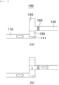
- FIG. 1 is a sectional view schematically showing a venting device according to an embodiment of the present invention.
- the venting device 100 includes a gas inlet 110, a gas outlet 120, a sealing cap 130, a connection portion 140, and an alarm means 150.
- the gas inlet 110 is a part that has one side coupled to a battery cell or a battery module and serves as a path through which gas is introduced into the venting device 100 from the interior thereof, and the gas outlet 120 is a part that serves as a path through which the gas introduced from the gas inlet 110 is discharged to the outside of the venting device 100.
- Each of the gas inlet and the gas outlet may generally be configured in the form of a pipe. However, the present invention is not limited thereto, and various forms capable of introducing and discharging gas may be employed.
- connection portion 140 is provided between the gas inlet 110 and the gas outlet 120 so as to connect the gas inlet and the gas outlet to each other, and a protrusion 141 configured to space a lower surface of the sealing cap 130 and a bottom surface of the connection portion 140 apart from each other is provided at a lower end of the connection portion 140.
- the gas inlet 110 is located at a lower end of the connection portion 140 while the gas outlet 120 is located at about a middle part of the connection portion 140 in a direction opposite the gas inlet 110, as shown in FIG. 1 .
- the gas outlet 120 may be provided at various positions, such as a direction perpendicular to the gas inlet 110, not the direction opposite the gas inlet 110.
- connection portion 140 the sealing cap 130 movable in the connection portion 140 is located.
- the sealing cap 130 In a normal state, i.e. when the pressure of gas in the battery cell or the battery module is similar to external air pressure, the sealing cap 130 is located at the lower end of the connection portion 140 to block the flow of gas between the gas inlet 110 and the gas outlet 120, as shown in (a) of FIG. 1 .
- the sealing cap 130 When gas is generated in the battery cell and thus gas pressure in the battery cell or the battery module is increased, however, the sealing cap 130 is raised in the connection portion 140 by the internal gas pressure, as shown in (b) of FIG. 1 .
- gas introduced from the gas inlet 110 may be discharged to the gas outlet 120 through the connection portion 140.
- the sealing cap 130 is lowered to the lower end of the connection portion 140 to block the discharge of gas and the introduction of air from the outside.
- the material for each of the gas inlet 110, the gas outlet 120, the sealing cap 130, and the connection portion 140 of the venting device 100 may be appropriately selected from among plastics and metals that exhibit high shapeability and heat resistance.
- the alarm means 150 which generates sound at the time of gas discharge to inform of the gas discharge, is provided at the gas outlet 120.
- the alarm means 150 may be used as the alarm means 150, and the alarm means may be appropriately located in the gas outlet 120.
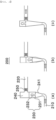
- FIG. 2 is a view schematically showing a venting device according to another embodiment of the present invention.
- the venting device 200 When describing the venting device 200 different in shape and operating mechanism from the venting device 100 described above with reference to FIG. 2 , the venting device 200 includes a gas inlet 210, a gas outlet 220, a sealing cap 230, a connection portion 240, and an alarm means 250.
- the functions and positions of the gas inlet 210 and the gas outlet 220 are similar to those of the venting device 100 of FIG. 1 , and therefore a separate description thereof will be omitted.
- connection portion 240 has a pipe form configured such that a lower part of the pipe, which is a part connected to the gas inlet 210, is narrow, and the pipe is gradually widened upwards, whereby the pipe has a trapezoidal section, and thereafter the pipe has a constant width.
- connection portion 240 is made of a heat shrink tube 241 configured to shrink at a predetermined temperature or higher.
- the heat shrink tube 241 which is a tube having characteristics in which the tub shrinks at a predetermined temperature or higher, may be made of various polymer materials, which may be appropriately combined or selected to set the shrink temperature to a desired range.
- various materials such as polyethylene (PE), polypropylene (PP), polyethylene terephthalate (PET), polyvinylidene fluoride (PVDF), polyvinylchloride (PVC), polytetrafluorethylene (PTFE), and silicone, may be used alone or in a mixed state.
- PE polyethylene
- PP polypropylene
- PET polyethylene terephthalate
- PVDF polyvinylidene fluoride
- PVDF polyvinylchloride
- PTFE polytetrafluorethylene
- silicone silicone
- the heat shrink tube 241 according to the present invention is formed including a mixture of polyethylene (PE) and polypropylene (PP), silicone, or PET in consideration of the shrink temperature thereof, etc.
- the heat shrink tube 241 is preferable for the heat shrink tube 241 to be made of a material that shrinks at the lowest temperature at the entirety of the connection portion 240 at a part close to the gas inlet 210 and a material that shrinks at a higher temperature with an increase in distance from the gas inlet 210.
- the sealing cap 230 is located in the connection portion 240 made of the heat shrink tube 241.
- the sealing cap 230 includes a main body portion 231 and a recessed portion 232 formed in a lower surface of the main body portion 231, and it is preferable for the sealing cap to be made of a heat resistant material that does not shrink even at the temperature at which the heat shrink tube 241 shrinks.
- the sealing cap 230 prefferably has a size corresponding to the inner diameter of the connection portion 240 such that the sealing cap is located at a uniform width part of the connection portion 240 to block the flow of gas between the gas inlet 210 and the gas outlet 220.
- the alarm means 250 which is capable of informing of gas discharge using sound, is attached to the gas outlet 220.
- FIG. 2 shows a normal state in which internal temperature is lower than the shrink temperature of the heat shrink tube 241.
- the sealing cap 230 in the connection portion 240 is located immediately above the narrow part of the connection portion 240 to block the flow of gas between the gas inlet 210 and the gas outlet 220.
- the heat shrink tube 241 made of the lowest shrink temperature material starts to shrink from a lower side thereof, as shown in (b) of FIG. 2 .
- a part of the lower surface of the sealing cap 230, in which the recessed portion 232 is formed shrinks and is pushed upwards to an upper side of the connection portion 240.
- the sealing cap 230 is raised to an upper end of the connection portion 240, as shown in (c) of FIG. 2 .
- the gas inlet 210 and the gas outlet 220 are connected to each other, whereby gas is discharged.
- the venting device 100 or 200 blocks the introduction of air from the outside in a normal state and automatically discharges internal gas under a predetermined condition, whereby an effect of preventing explosion, fire outbreak, etc. due to the generation of gas may be achieved, and gas discharge may be checked through sound using the alarm means 150 or 250.
- the venting device 100 or 200 may be attached to various battery products, such as a battery pack, in addition to the battery cell or the battery module mentioned above, and the number of venting devices 100 or 200 to be attached may be appropriately selected as needed.
- venting devices 100 and 200 having different operating mechanisms may be simultaneously attached to one battery product.
Landscapes
- Chemical & Material Sciences (AREA)
- Chemical Kinetics & Catalysis (AREA)
- Electrochemistry (AREA)
- General Chemical & Material Sciences (AREA)
- Engineering & Computer Science (AREA)
- General Engineering & Computer Science (AREA)
- Manufacturing & Machinery (AREA)
- Mechanical Engineering (AREA)
- Gas Exhaust Devices For Batteries (AREA)
- Sealing Battery Cases Or Jackets (AREA)
Abstract
Description
- This application claims the benefit of priority to
Korean Patent Application No. 2021-0092129 filed on July 14, 2021 - The present invention relates to a venting device capable of automatically discharging gas generated in a battery cell to the outside and a battery module including the same.
- With technological development of mobile devices, such as smartphones, laptop computers, and digital cameras, and an increase in demand therefor, research on secondary batteries, which are capable of being charged and discharged, has been actively conducted. In addition, secondary batteries, which are energy sources substituting for fossil fuels causing air pollution, have been applied to an electric vehicle (EV), a hybrid electric vehicle (HEV), a plug-in hybrid electric vehicle (P-HEV), and an energy storage system (ESS).
- There are a lithium ion battery, a lithium polymer battery, a nickel-cadmium battery, a nickel-hydride battery, and a nickel-zinc battery as secondary batteries that are widely used at present. The operating voltage of a unit secondary battery cell, i.e. a unit battery cell, is about 2.0V to 5.0V. When output voltage higher than the above operating voltage is required, therefore, a plurality of battery cells may be connected to each other in series to constitute a cell module assembly. In addition, cell module assemblies may be connected to each other in series or in parallel to constitute a battery module depending on required output voltage or charge and discharge capacities. In general, a battery pack is manufactured using at least one battery module by adding an additional component.
- During use of the battery pack, gas may be generated from the battery cell. Gas may be generated due to exposure to high temperature, internal short circuit, overcharging, or reaction between an electrolyte and an electrode active material caused by repeated charging and discharging.
- If the pressure or temperature in the battery cell is increased due to such generation of gas, problems, such as damage to a battery case, internal short circuit, explosion, and fire outbreak, may occur.
- In order to prevent these problems, the battery cell may be provided with a structure capable of discharging gas, or a battery module or a battery pack including the battery cell may be provided with a venting device.
- In most conventional venting devices, however, emphasis is placed only on discharging of internal gas, and therefore a device capable of rapidly checking whether gas is generated and at the same time automatically discharging the generated gas is required.
- The present invention has been made in view of the above problems, and it is an object of the present invention to provide a venting device capable of automatically discharging gas depending on internal gas pressure or internal temperature and having an alarm means configured to inform thereof and a battery module including the same.
- A venting device according to the present invention to accomplish the above object is a venting device provided at one side of a battery cell or a battery module and configured to discharge gas in the battery cell or the battery module to an outside, the venting device including a gas inlet configured to allow gas in the battery cell or the battery module to be introduced therethrough, a gas outlet configured to allow the gas introduced through the gas inlet to be discharged to the outside therethrough, an alarm means provided at one side of the gas outlet, the alarm means being configured to generate a sound when the gas is discharged to the outside, a connection portion configured to connect the gas inlet and the gas outlet to each other, and a sealing cap located in the connection portion, the sealing cap being configured to automatically discharge gas to the outside, wherein the sealing cap blocks connection between the gas inlet and the gas outlet, thereby blocking discharge of gas and introduction of external air, in a normal state, and moves in the connection portion under a predetermined condition such that the gas inlet and the gas outlet are connected to each other.
- Also, in the venting device according to the present invention, when the pressure of gas in the battery cell or the battery module is increased to a predetermined level or higher, the sealing cap may move in the connection portion such that the gas inlet and the gas outlet are connected to each other.
- Also, in the venting device according to the present invention, when the internal temperature is increased to a predetermined level or higher due to gas generated in the battery cell or the battery module, the sealing cap may move in the connection portion such that the gas inlet and the gas outlet are connected to each other.
- Also, in the venting device according to the present invention, the connection portion may be made of a heat shrink tube configured to shrink at a predetermined temperature or higher.
- Also, in the venting device according to the present invention, the heat shrink tube may be formed from polyethylene (PE) and polypropylene (PP).
- Also, in the venting device according to the present invention, the heat shrink tube may be formed from silicone.
- Also, in the venting device according to the present invention, the heat shrink tube may be formed from polyethylene terephthalate (PET).
- Also, in the venting device according to the present invention, the sealing cap may include a main body portion and a recessed portion formed at one side of the main body portion such that a part of the main body portion shrinks when the heat shrink tube shrinks.
- Also, in the venting device according to the present invention, a part of the heat shrink tube close to the gas inlet may thermally shrink at the lowest temperature.
- In addition, a battery cell according to the present invention has the venting device according to the present invention.
- In addition, a battery module according to the present invention has the venting device according to the present invention.
- A venting device according to the present invention has an advantage in that a sealing cap configured to be automatically opened and closed depending on gas pressure is provided, whereby it is possible to automatically discharge gas in a battery cell or a battery module when the pressure of the gas is equal to or greater than a predetermined level and to block the introduction of air from the outside when the pressure of the gas is less than the predetermined level.
- In addition, the venting device according to the present invention has an advantage in that a sealing cap configured to be automatically opened and closed depending on temperature is provided, whereby it is possible to automatically discharge gas when the temperature in the battery cell or the battery module is equal to or greater than a predetermined level and to block the introduction of air from the outside when the temperature is less than the predetermined level.
- In addition, the venting device according to the present invention has an advantage in that an alarm means is provided, whereby it is possible to check gas discharge in real time.
- In addition, the venting device according to the present invention has an advantage in that the venting device is applied to the battery cell or the battery module, whereby it is possible to reduce a danger of explosion or damage due to an increase in internal gas pressure.
-
-
FIG. 1 is a sectional view schematically showing a venting device according to an embodiment of the present invention. -
FIG. 2 is a view schematically showing a venting device according to another embodiment of the present invention. - In the present application, it should be understood that the terms "comprises," "has," "includes," etc. specify the presence of stated features, numbers, steps, operations, elements, components, or combinations thereof, but do not preclude the presence or addition of one or more other features, numbers, steps, operations, elements, components, or combinations thereof.
- In addition, the same reference numbers will be used throughout the drawings to refer to parts that perform similar functions or operations. In the case in which one part is said to be connected to another part in the specification, not only may the one part be directly connected to the other part, but also, the one part may be indirectly connected to the other part via a further part. In addition, that a certain element is included does not mean that other elements are excluded, but means that such elements may be further included unless mentioned otherwise.
- Hereinafter, a venting device according to the present invention will be described with reference to the accompanying drawings.
-
FIG. 1 is a sectional view schematically showing a venting device according to an embodiment of the present invention. - When describing the
venting device 100 according to the present invention with reference toFIG. 1 , theventing device 100 includes agas inlet 110, agas outlet 120, asealing cap 130, aconnection portion 140, and an alarm means 150. - The
gas inlet 110 is a part that has one side coupled to a battery cell or a battery module and serves as a path through which gas is introduced into theventing device 100 from the interior thereof, and thegas outlet 120 is a part that serves as a path through which the gas introduced from thegas inlet 110 is discharged to the outside of theventing device 100. Each of the gas inlet and the gas outlet may generally be configured in the form of a pipe. However, the present invention is not limited thereto, and various forms capable of introducing and discharging gas may be employed. - In addition, the
connection portion 140 is provided between thegas inlet 110 and thegas outlet 120 so as to connect the gas inlet and the gas outlet to each other, and aprotrusion 141 configured to space a lower surface of thesealing cap 130 and a bottom surface of theconnection portion 140 apart from each other is provided at a lower end of theconnection portion 140. - When describing the positions of the
gas inlet 110 and thegas outlet 120 attached to theconnection portion 140, thegas inlet 110 is located at a lower end of theconnection portion 140 while thegas outlet 120 is located at about a middle part of theconnection portion 140 in a direction opposite thegas inlet 110, as shown inFIG. 1 . - Of course, depending on circumstances, the
gas outlet 120 may be provided at various positions, such as a direction perpendicular to thegas inlet 110, not the direction opposite thegas inlet 110. - In the
connection portion 140, thesealing cap 130 movable in theconnection portion 140 is located. In a normal state, i.e. when the pressure of gas in the battery cell or the battery module is similar to external air pressure, the sealingcap 130 is located at the lower end of theconnection portion 140 to block the flow of gas between thegas inlet 110 and thegas outlet 120, as shown in (a) ofFIG. 1 . - When gas is generated in the battery cell and thus gas pressure in the battery cell or the battery module is increased, however, the sealing
cap 130 is raised in theconnection portion 140 by the internal gas pressure, as shown in (b) ofFIG. 1 . When the sealing cap is raised higher than the coupling portion with thegas outlet 120, gas introduced from thegas inlet 110 may be discharged to thegas outlet 120 through theconnection portion 140. - Afterwards, when the internal gas pressure is lowered due to discharge of the gas, the sealing
cap 130 is lowered to the lower end of theconnection portion 140 to block the discharge of gas and the introduction of air from the outside. - The material for each of the
gas inlet 110, thegas outlet 120, thesealing cap 130, and theconnection portion 140 of theventing device 100 may be appropriately selected from among plastics and metals that exhibit high shapeability and heat resistance. - In addition, the alarm means 150, which generates sound at the time of gas discharge to inform of the gas discharge, is provided at the
gas outlet 120. - Various known devices that generate sound when gas flows may be used as the alarm means 150, and the alarm means may be appropriately located in the
gas outlet 120. - Meanwhile,
FIG. 2 is a view schematically showing a venting device according to another embodiment of the present invention. - When describing the
venting device 200 different in shape and operating mechanism from theventing device 100 described above with reference toFIG. 2 , theventing device 200 includes agas inlet 210, agas outlet 220, asealing cap 230, aconnection portion 240, and an alarm means 250. - Here, the functions and positions of the
gas inlet 210 and thegas outlet 220 are similar to those of theventing device 100 ofFIG. 1 , and therefore a separate description thereof will be omitted. - The
connection portion 240 has a pipe form configured such that a lower part of the pipe, which is a part connected to thegas inlet 210, is narrow, and the pipe is gradually widened upwards, whereby the pipe has a trapezoidal section, and thereafter the pipe has a constant width. - In addition, the
connection portion 240 is made of aheat shrink tube 241 configured to shrink at a predetermined temperature or higher. - The
heat shrink tube 241, which is a tube having characteristics in which the tub shrinks at a predetermined temperature or higher, may be made of various polymer materials, which may be appropriately combined or selected to set the shrink temperature to a desired range. - As the material used in the
heat shrink tube 241, various materials, such as polyethylene (PE), polypropylene (PP), polyethylene terephthalate (PET), polyvinylidene fluoride (PVDF), polyvinylchloride (PVC), polytetrafluorethylene (PTFE), and silicone, may be used alone or in a mixed state. - It is preferable for the
heat shrink tube 241 according to the present invention to be formed including a mixture of polyethylene (PE) and polypropylene (PP), silicone, or PET in consideration of the shrink temperature thereof, etc. - Also, it is preferable for the
heat shrink tube 241 to be made of a material that shrinks at the lowest temperature at the entirety of theconnection portion 240 at a part close to thegas inlet 210 and a material that shrinks at a higher temperature with an increase in distance from thegas inlet 210. - Meanwhile, the sealing
cap 230 is located in theconnection portion 240 made of theheat shrink tube 241. - The sealing
cap 230 includes amain body portion 231 and a recessedportion 232 formed in a lower surface of themain body portion 231, and it is preferable for the sealing cap to be made of a heat resistant material that does not shrink even at the temperature at which theheat shrink tube 241 shrinks. - It is preferable for the sealing
cap 230 to have a size corresponding to the inner diameter of theconnection portion 240 such that the sealing cap is located at a uniform width part of theconnection portion 240 to block the flow of gas between thegas inlet 210 and thegas outlet 220. - In addition, the alarm means 250, which is capable of informing of gas discharge using sound, is attached to the
gas outlet 220. - When describing the operating mechanism of the
venting device 200 having the above construction with reference toFIG. 2, (a) ofFIG. 2 shows a normal state in which internal temperature is lower than the shrink temperature of theheat shrink tube 241. - In the normal state, the sealing
cap 230 in theconnection portion 240 is located immediately above the narrow part of theconnection portion 240 to block the flow of gas between thegas inlet 210 and thegas outlet 220. - When the temperature in the battery cell or the battery module is increased due to generation of gas, however, the
heat shrink tube 241 made of the lowest shrink temperature material starts to shrink from a lower side thereof, as shown in (b) ofFIG. 2 . As a result, a part of the lower surface of the sealingcap 230, in which the recessedportion 232 is formed, shrinks and is pushed upwards to an upper side of theconnection portion 240. - When this process is continuously performed, the sealing
cap 230 is raised to an upper end of theconnection portion 240, as shown in (c) ofFIG. 2 . As a result, thegas inlet 210 and thegas outlet 220 are connected to each other, whereby gas is discharged. - When the internal temperature is lowered as the result of gas discharge, the
heat shrink tube 241 is relaxed to the original shape thereof. As a result, the sealingcap 230 moves downwards to block the flow of air, as shown in (a) ofFIG. 2 . - As described above, the
venting device - The
venting device devices - In addition, two venting
devices - Although the specific details of the present invention have been described in detail, those skilled in the art will appreciate that the detailed description thereof discloses only preferred embodiments of the present invention and thus does not limit the scope of the present invention. Accordingly, those skilled in the art will appreciate that various changes and modifications are possible, without departing from the category and technical idea of the present invention, and it will be obvious that such changes and modifications fall within the scope of the appended claims.
-
- 100, 200: Venting devices
- 110, 210: Gas inlets
- 120, 220: Gas outlets
- 130, 230: Sealing caps
- 231: Main body portion
- 232: Recessed portion
- 140, 240: Connection portions
- 141: Protrusion
- 241: Heat shrink tube
- 150, 250: Alarm means
Claims (11)
- A venting device provided at one side of a battery cell or a battery module and configured to discharge gas in the battery cell or the battery module to an outside, the venting device comprising:a gas inlet configured to allow gas in the battery cell or the battery module to be introduced therethrough;a gas outlet configured to allow the gas introduced through the gas inlet to be discharged to the outside therethrough;an alarm means provided at one side of the gas outlet, the alarm means being configured to generate a sound when the gas is discharged to the outside;a connection portion configured to connect the gas inlet and the gas outlet to each other; anda sealing cap located in the connection portion, the sealing cap being configured to automatically discharge gas to the outside, whereinthe sealing cap blocks connection between the gas inlet and the gas outlet, thereby blocking discharge of gas and introduction of external air, in a normal state, and moves in the connection portion under a predetermined condition such that the gas inlet and the gas outlet are connected to each other.
- The venting device according to claim 1, wherein, when a pressure of gas in the battery cell or the battery module is increased to a predetermined level or higher, the sealing cap moves in the connection portion such that the gas inlet and the gas outlet are connected to each other.
- The venting device according to claim 1, wherein, when an internal temperature is increased to a predetermined level or higher due to gas generated in the battery cell or the battery module, the sealing cap moves in the connection portion such that the gas inlet and the gas outlet are connected to each other.
- The venting device according to claim 3, wherein the connection portion is made of a heat shrink tube configured to shrink at a predetermined temperature or higher.
- The venting device according to claim 4, wherein the heat shrink tube is formed from polyethylene (PE) and polypropylene (PP).
- The venting device according to claim 4, wherein the heat shrink tube is formed from silicone.
- The venting device according to claim 4, wherein the heat shrink tube is formed from polyethylene terephthalate (PET).
- The venting device according to claim 4, wherein the sealing cap comprises a main body portion and a recessed portion formed at one side of the main body portion such that a part of the main body portion shrinks when the heat shrink tube shrinks.
- The venting device according to claim 4, wherein a part of the heat shrink tube close to the gas inlet thermally shrinks at a lowest temperature.
- A battery cell having the venting device according to any one of claims 1 to 9.
- A battery module having the venting device according to any one of claims 1 to 9.
Applications Claiming Priority (2)
| Application Number | Priority Date | Filing Date | Title |
|---|---|---|---|
| KR1020210092129A KR102935497B1 (en) | 2021-07-14 | 2021-07-14 | Venting device including sealing cap and battery module including same |
| PCT/KR2022/009045 WO2023287056A1 (en) | 2021-07-14 | 2022-06-24 | Venting device and battery module including same |
Publications (3)
| Publication Number | Publication Date |
|---|---|
| EP4181299A1 true EP4181299A1 (en) | 2023-05-17 |
| EP4181299A4 EP4181299A4 (en) | 2024-10-16 |
| EP4181299B1 EP4181299B1 (en) | 2025-07-30 |
Family
ID=84919462
Family Applications (1)
| Application Number | Title | Priority Date | Filing Date |
|---|---|---|---|
| EP22842318.2A Active EP4181299B1 (en) | 2021-07-14 | 2022-06-24 | Venting device and battery module including the same |
Country Status (6)
| Country | Link |
|---|---|
| EP (1) | EP4181299B1 (en) |
| JP (1) | JP7527715B2 (en) |
| KR (1) | KR102935497B1 (en) |
| ES (1) | ES3037988T3 (en) |
| HU (1) | HUE072523T2 (en) |
| WO (1) | WO2023287056A1 (en) |
Family Cites Families (14)
| Publication number | Priority date | Publication date | Assignee | Title |
|---|---|---|---|---|
| JPH10184373A (en) * | 1996-12-27 | 1998-07-14 | Fuji Oozx Inc | Relief valve device with audible alarm in engine |
| JPH10334875A (en) * | 1997-06-04 | 1998-12-18 | Toyota Motor Corp | Lithium ion secondary battery |
| JP3539620B2 (en) * | 1999-02-04 | 2004-07-07 | トヨタ自動車株式会社 | Rechargeable battery |
| JP2006040626A (en) * | 2004-07-23 | 2006-02-09 | Toyota Motor Corp | Sealed secondary battery |
| CN2872043Y (en) * | 2006-02-10 | 2007-02-21 | 中国气动工业股份有限公司 | Universal air inlet joint for multifunctional portable pneumatic tools |
| KR101310435B1 (en) * | 2010-12-20 | 2013-09-24 | 삼성전기주식회사 | An air valve for energy storage device and energy storage device including the same |
| KR101316319B1 (en) * | 2011-10-10 | 2013-10-08 | 기아자동차주식회사 | Air breather for high voltage battery of vehicle |
| CN203131137U (en) * | 2012-12-10 | 2013-08-14 | 中国人民解放军63971部队 | Safe gas discharging valve |
| KR20160109513A (en) * | 2015-03-11 | 2016-09-21 | 삼성에스디아이 주식회사 | Battery pack |
| CN206786085U (en) * | 2017-05-31 | 2017-12-22 | 李志宏 | A kind of safety valve for pressure pipeline |
| KR102448322B1 (en) * | 2018-11-21 | 2022-09-29 | 주식회사 엘지에너지솔루션 | battery pack |
| JP2021012761A (en) * | 2019-07-03 | 2021-02-04 | 三菱自動車工業株式会社 | Abnormality detection device of battery pack |
| US11205243B2 (en) | 2020-01-14 | 2021-12-21 | Arm Limited | Data processing systems |
| US20240380068A1 (en) * | 2021-06-18 | 2024-11-14 | Lg Energy Solution, Ltd. | Vent Sealing Cap for Secondary Battery and Secondary Battery Including the Same |
-
2021
- 2021-07-14 KR KR1020210092129A patent/KR102935497B1/en active Active
-
2022
- 2022-06-24 WO PCT/KR2022/009045 patent/WO2023287056A1/en not_active Ceased
- 2022-06-24 EP EP22842318.2A patent/EP4181299B1/en active Active
- 2022-06-24 JP JP2023506325A patent/JP7527715B2/en active Active
- 2022-06-24 HU HUE22842318A patent/HUE072523T2/en unknown
- 2022-06-24 ES ES22842318T patent/ES3037988T3/en active Active
Also Published As
| Publication number | Publication date |
|---|---|
| CN116114111A (en) | 2023-05-12 |
| JP7527715B2 (en) | 2024-08-05 |
| KR102935497B1 (en) | 2026-03-06 |
| KR20230011645A (en) | 2023-01-25 |
| JP2023537876A (en) | 2023-09-06 |
| HUE072523T2 (en) | 2025-11-28 |
| EP4181299A4 (en) | 2024-10-16 |
| ES3037988T3 (en) | 2025-10-08 |
| WO2023287056A1 (en) | 2023-01-19 |
| EP4181299B1 (en) | 2025-07-30 |
| US20230268611A1 (en) | 2023-08-24 |
Similar Documents
| Publication | Publication Date | Title |
|---|---|---|
| US11942617B2 (en) | Battery module, and battery rack and energy storage system including the same | |
| EP3509134B1 (en) | Safety-improved battery cell including thermal expansion tape and method of manufacturing same | |
| EP3982475A1 (en) | Battery module, and battery rack and power storage device comprising battery module | |
| EP4117092A1 (en) | Battery pack comprising structure for suppressing thermal diffusion | |
| KR20190002992A (en) | Secondary cell | |
| CN115917867A (en) | Secondary battery and device including same | |
| US12592448B2 (en) | Battery module, and battery pack and vehicle comprising same | |
| EP4181299B1 (en) | Venting device and battery module including the same | |
| US12633618B2 (en) | Venting device and battery module including the same | |
| CN116114111B (en) | Exhaust device, battery cell, and battery module including exhaust device | |
| EP4020673A1 (en) | Cylindrical battery and method for manufacturing cylindrical battery | |
| KR20220077517A (en) | Battery pack having gas discharging unit | |
| EP4329070A1 (en) | Vent sealing cap for secondary battery and secondary battery comprising same | |
| US20220238954A1 (en) | Venting Device for Secondary Batteries and Pouch-Shaped Secondary Battery Including the Same | |
| KR102328738B1 (en) | Overdischarge test appratus | |
| KR102850649B1 (en) | Cooling apparatus for double-sided type battery module | |
| EP4496100A1 (en) | Battery pack for releasing internal pressure during thermal runaway | |
| EP4383420A1 (en) | Rechargeable battery module | |
| KR20220169418A (en) | Vent sealing cap for secondary battery and secondary battery including same | |
| KR101690576B1 (en) | Secondary battery | |
| CN118661327A (en) | Battery pack and vehicle including the battery pack | |
| KR20260033364A (en) | Battery cell and battery module including the same | |
| KR20240085140A (en) | Rechargeable battery module |
Legal Events
| Date | Code | Title | Description |
|---|---|---|---|
| STAA | Information on the status of an ep patent application or granted ep patent |
Free format text: STATUS: THE INTERNATIONAL PUBLICATION HAS BEEN MADE |
|
| PUAI | Public reference made under article 153(3) epc to a published international application that has entered the european phase |
Free format text: ORIGINAL CODE: 0009012 |
|
| STAA | Information on the status of an ep patent application or granted ep patent |
Free format text: STATUS: REQUEST FOR EXAMINATION WAS MADE |
|
| 17P | Request for examination filed |
Effective date: 20230213 |
|
| AK | Designated contracting states |
Kind code of ref document: A1 Designated state(s): AL AT BE BG CH CY CZ DE DK EE ES FI FR GB GR HR HU IE IS IT LI LT LU LV MC MK MT NL NO PL PT RO RS SE SI SK SM TR |
|
| RIC1 | Information provided on ipc code assigned before grant |
Ipc: H01M 10/48 20060101ALI20240531BHEP Ipc: H01M 50/325 20210101ALI20240531BHEP Ipc: H01M 50/317 20210101AFI20240531BHEP |
|
| A4 | Supplementary search report drawn up and despatched |
Effective date: 20240912 |
|
| RIC1 | Information provided on ipc code assigned before grant |
Ipc: H01M 10/48 20060101ALI20240906BHEP Ipc: H01M 50/325 20210101ALI20240906BHEP Ipc: H01M 50/317 20210101AFI20240906BHEP |
|
| DAV | Request for validation of the european patent (deleted) | ||
| DAX | Request for extension of the european patent (deleted) | ||
| GRAP | Despatch of communication of intention to grant a patent |
Free format text: ORIGINAL CODE: EPIDOSNIGR1 |
|
| STAA | Information on the status of an ep patent application or granted ep patent |
Free format text: STATUS: GRANT OF PATENT IS INTENDED |
|
| INTG | Intention to grant announced |
Effective date: 20250124 |
|
| GRAJ | Information related to disapproval of communication of intention to grant by the applicant or resumption of examination proceedings by the epo deleted |
Free format text: ORIGINAL CODE: EPIDOSDIGR1 |
|
| STAA | Information on the status of an ep patent application or granted ep patent |
Free format text: STATUS: REQUEST FOR EXAMINATION WAS MADE |
|
| P01 | Opt-out of the competence of the unified patent court (upc) registered |
Free format text: CASE NUMBER: APP_6068/2025 Effective date: 20250205 |
|
| GRAP | Despatch of communication of intention to grant a patent |
Free format text: ORIGINAL CODE: EPIDOSNIGR1 |
|
| STAA | Information on the status of an ep patent application or granted ep patent |
Free format text: STATUS: GRANT OF PATENT IS INTENDED |
|
| INTG | Intention to grant announced |
Effective date: 20250318 |
|
| GRAS | Grant fee paid |
Free format text: ORIGINAL CODE: EPIDOSNIGR3 |
|
| GRAA | (expected) grant |
Free format text: ORIGINAL CODE: 0009210 |
|
| STAA | Information on the status of an ep patent application or granted ep patent |
Free format text: STATUS: THE PATENT HAS BEEN GRANTED |
|
| AK | Designated contracting states |
Kind code of ref document: B1 Designated state(s): AL AT BE BG CH CY CZ DE DK EE ES FI FR GB GR HR HU IE IS IT LI LT LU LV MC MK MT NL NO PL PT RO RS SE SI SK SM TR |
|
| REG | Reference to a national code |
Ref country code: GB Ref legal event code: FG4D |
|
| REG | Reference to a national code |
Ref country code: CH Ref legal event code: EP |
|
| REG | Reference to a national code |
Ref country code: DE Ref legal event code: R096 Ref document number: 602022018650 Country of ref document: DE |
|
| REG | Reference to a national code |
Ref country code: IE Ref legal event code: FG4D |
|
| REG | Reference to a national code |
Ref country code: ES Ref legal event code: FG2A Ref document number: 3037988 Country of ref document: ES Kind code of ref document: T3 Effective date: 20251008 |
|
| REG | Reference to a national code |
Ref country code: HU Ref legal event code: AG4A Ref document number: E072523 Country of ref document: HU |
|
| REG | Reference to a national code |
Ref country code: NL Ref legal event code: MP Effective date: 20250730 |
|
| REG | Reference to a national code |
Ref country code: AT Ref legal event code: MK05 Ref document number: 1820064 Country of ref document: AT Kind code of ref document: T Effective date: 20250730 |
|
| PG25 | Lapsed in a contracting state [announced via postgrant information from national office to epo] |
Ref country code: PT Free format text: LAPSE BECAUSE OF FAILURE TO SUBMIT A TRANSLATION OF THE DESCRIPTION OR TO PAY THE FEE WITHIN THE PRESCRIBED TIME-LIMIT Effective date: 20251202 |
|
| PG25 | Lapsed in a contracting state [announced via postgrant information from national office to epo] |
Ref country code: IS Free format text: LAPSE BECAUSE OF FAILURE TO SUBMIT A TRANSLATION OF THE DESCRIPTION OR TO PAY THE FEE WITHIN THE PRESCRIBED TIME-LIMIT Effective date: 20251130 |
|
| PG25 | Lapsed in a contracting state [announced via postgrant information from national office to epo] |
Ref country code: NO Free format text: LAPSE BECAUSE OF FAILURE TO SUBMIT A TRANSLATION OF THE DESCRIPTION OR TO PAY THE FEE WITHIN THE PRESCRIBED TIME-LIMIT Effective date: 20251030 |
|
| REG | Reference to a national code |
Ref country code: LT Ref legal event code: MG9D |
|
| PG25 | Lapsed in a contracting state [announced via postgrant information from national office to epo] |
Ref country code: AT Free format text: LAPSE BECAUSE OF FAILURE TO SUBMIT A TRANSLATION OF THE DESCRIPTION OR TO PAY THE FEE WITHIN THE PRESCRIBED TIME-LIMIT Effective date: 20250730 |
|
| PG25 | Lapsed in a contracting state [announced via postgrant information from national office to epo] |
Ref country code: FI Free format text: LAPSE BECAUSE OF FAILURE TO SUBMIT A TRANSLATION OF THE DESCRIPTION OR TO PAY THE FEE WITHIN THE PRESCRIBED TIME-LIMIT Effective date: 20250730 |
|
| PG25 | Lapsed in a contracting state [announced via postgrant information from national office to epo] |
Ref country code: HR Free format text: LAPSE BECAUSE OF FAILURE TO SUBMIT A TRANSLATION OF THE DESCRIPTION OR TO PAY THE FEE WITHIN THE PRESCRIBED TIME-LIMIT Effective date: 20250730 Ref country code: NL Free format text: LAPSE BECAUSE OF FAILURE TO SUBMIT A TRANSLATION OF THE DESCRIPTION OR TO PAY THE FEE WITHIN THE PRESCRIBED TIME-LIMIT Effective date: 20250730 |
|
| PG25 | Lapsed in a contracting state [announced via postgrant information from national office to epo] |
Ref country code: GR Free format text: LAPSE BECAUSE OF FAILURE TO SUBMIT A TRANSLATION OF THE DESCRIPTION OR TO PAY THE FEE WITHIN THE PRESCRIBED TIME-LIMIT Effective date: 20251031 |
|
| PG25 | Lapsed in a contracting state [announced via postgrant information from national office to epo] |
Ref country code: SE Free format text: LAPSE BECAUSE OF FAILURE TO SUBMIT A TRANSLATION OF THE DESCRIPTION OR TO PAY THE FEE WITHIN THE PRESCRIBED TIME-LIMIT Effective date: 20250730 |
|
| PG25 | Lapsed in a contracting state [announced via postgrant information from national office to epo] |
Ref country code: LV Free format text: LAPSE BECAUSE OF FAILURE TO SUBMIT A TRANSLATION OF THE DESCRIPTION OR TO PAY THE FEE WITHIN THE PRESCRIBED TIME-LIMIT Effective date: 20250730 |
|
| PG25 | Lapsed in a contracting state [announced via postgrant information from national office to epo] |
Ref country code: BG Free format text: LAPSE BECAUSE OF FAILURE TO SUBMIT A TRANSLATION OF THE DESCRIPTION OR TO PAY THE FEE WITHIN THE PRESCRIBED TIME-LIMIT Effective date: 20250730 Ref country code: PL Free format text: LAPSE BECAUSE OF FAILURE TO SUBMIT A TRANSLATION OF THE DESCRIPTION OR TO PAY THE FEE WITHIN THE PRESCRIBED TIME-LIMIT Effective date: 20250730 |
|
| PG25 | Lapsed in a contracting state [announced via postgrant information from national office to epo] |
Ref country code: RS Free format text: LAPSE BECAUSE OF FAILURE TO SUBMIT A TRANSLATION OF THE DESCRIPTION OR TO PAY THE FEE WITHIN THE PRESCRIBED TIME-LIMIT Effective date: 20251030 |
|
| PG25 | Lapsed in a contracting state [announced via postgrant information from national office to epo] |
Ref country code: SM Free format text: LAPSE BECAUSE OF FAILURE TO SUBMIT A TRANSLATION OF THE DESCRIPTION OR TO PAY THE FEE WITHIN THE PRESCRIBED TIME-LIMIT Effective date: 20250730 |
|
| PG25 | Lapsed in a contracting state [announced via postgrant information from national office to epo] |
Ref country code: DK Free format text: LAPSE BECAUSE OF FAILURE TO SUBMIT A TRANSLATION OF THE DESCRIPTION OR TO PAY THE FEE WITHIN THE PRESCRIBED TIME-LIMIT Effective date: 20250730 |
|
| PG25 | Lapsed in a contracting state [announced via postgrant information from national office to epo] |
Ref country code: IT Free format text: LAPSE BECAUSE OF FAILURE TO SUBMIT A TRANSLATION OF THE DESCRIPTION OR TO PAY THE FEE WITHIN THE PRESCRIBED TIME-LIMIT Effective date: 20250730 |
|
| PG25 | Lapsed in a contracting state [announced via postgrant information from national office to epo] |
Ref country code: CZ Free format text: LAPSE BECAUSE OF FAILURE TO SUBMIT A TRANSLATION OF THE DESCRIPTION OR TO PAY THE FEE WITHIN THE PRESCRIBED TIME-LIMIT Effective date: 20250730 |
|
| PG25 | Lapsed in a contracting state [announced via postgrant information from national office to epo] |
Ref country code: EE Free format text: LAPSE BECAUSE OF FAILURE TO SUBMIT A TRANSLATION OF THE DESCRIPTION OR TO PAY THE FEE WITHIN THE PRESCRIBED TIME-LIMIT Effective date: 20250730 Ref country code: SK Free format text: LAPSE BECAUSE OF FAILURE TO SUBMIT A TRANSLATION OF THE DESCRIPTION OR TO PAY THE FEE WITHIN THE PRESCRIBED TIME-LIMIT Effective date: 20250730 |