EP4181289A1 - Battery module and battery pack comprising same - Google Patents
Battery module and battery pack comprising same Download PDFInfo
- Publication number
- EP4181289A1 EP4181289A1 EP21883041.2A EP21883041A EP4181289A1 EP 4181289 A1 EP4181289 A1 EP 4181289A1 EP 21883041 A EP21883041 A EP 21883041A EP 4181289 A1 EP4181289 A1 EP 4181289A1
- Authority
- EP
- European Patent Office
- Prior art keywords
- battery
- battery cell
- barrier
- barrier layer
- battery module
- Prior art date
- Legal status (The legal status is an assumption and is not a legal conclusion. Google has not performed a legal analysis and makes no representation as to the accuracy of the status listed.)
- Pending
Links
Images


Classifications
-
- H—ELECTRICITY
- H01—ELECTRIC ELEMENTS
- H01M—PROCESSES OR MEANS, e.g. BATTERIES, FOR THE DIRECT CONVERSION OF CHEMICAL ENERGY INTO ELECTRICAL ENERGY
- H01M50/00—Constructional details or processes of manufacture of the non-active parts of electrochemical cells other than fuel cells, e.g. hybrid cells
- H01M50/20—Mountings; Secondary casings or frames; Racks, modules or packs; Suspension devices; Shock absorbers; Transport or carrying devices; Holders
- H01M50/233—Mountings; Secondary casings or frames; Racks, modules or packs; Suspension devices; Shock absorbers; Transport or carrying devices; Holders characterised by physical properties of casings or racks, e.g. dimensions
- H01M50/24—Mountings; Secondary casings or frames; Racks, modules or packs; Suspension devices; Shock absorbers; Transport or carrying devices; Holders characterised by physical properties of casings or racks, e.g. dimensions adapted for protecting batteries from their environment, e.g. from corrosion
-
- H—ELECTRICITY
- H01—ELECTRIC ELEMENTS
- H01M—PROCESSES OR MEANS, e.g. BATTERIES, FOR THE DIRECT CONVERSION OF CHEMICAL ENERGY INTO ELECTRICAL ENERGY
- H01M10/00—Secondary cells; Manufacture thereof
- H01M10/60—Heating or cooling; Temperature control
- H01M10/61—Types of temperature control
- H01M10/613—Cooling or keeping cold
-
- H—ELECTRICITY
- H01—ELECTRIC ELEMENTS
- H01M—PROCESSES OR MEANS, e.g. BATTERIES, FOR THE DIRECT CONVERSION OF CHEMICAL ENERGY INTO ELECTRICAL ENERGY
- H01M50/00—Constructional details or processes of manufacture of the non-active parts of electrochemical cells other than fuel cells, e.g. hybrid cells
- H01M50/30—Arrangements for facilitating escape of gases
- H01M50/383—Flame arresting or ignition-preventing means
-
- H—ELECTRICITY
- H01—ELECTRIC ELEMENTS
- H01M—PROCESSES OR MEANS, e.g. BATTERIES, FOR THE DIRECT CONVERSION OF CHEMICAL ENERGY INTO ELECTRICAL ENERGY
- H01M10/00—Secondary cells; Manufacture thereof
- H01M10/60—Heating or cooling; Temperature control
- H01M10/65—Means for temperature control structurally associated with the cells
- H01M10/658—Means for temperature control structurally associated with the cells by thermal insulation or shielding
-
- H—ELECTRICITY
- H01—ELECTRIC ELEMENTS
- H01M—PROCESSES OR MEANS, e.g. BATTERIES, FOR THE DIRECT CONVERSION OF CHEMICAL ENERGY INTO ELECTRICAL ENERGY
- H01M50/00—Constructional details or processes of manufacture of the non-active parts of electrochemical cells other than fuel cells, e.g. hybrid cells
- H01M50/20—Mountings; Secondary casings or frames; Racks, modules or packs; Suspension devices; Shock absorbers; Transport or carrying devices; Holders
- H01M50/204—Racks, modules or packs for multiple batteries or multiple cells
- H01M50/207—Racks, modules or packs for multiple batteries or multiple cells characterised by their shape
- H01M50/211—Racks, modules or packs for multiple batteries or multiple cells characterised by their shape adapted for pouch cells
-
- H—ELECTRICITY
- H01—ELECTRIC ELEMENTS
- H01M—PROCESSES OR MEANS, e.g. BATTERIES, FOR THE DIRECT CONVERSION OF CHEMICAL ENERGY INTO ELECTRICAL ENERGY
- H01M50/00—Constructional details or processes of manufacture of the non-active parts of electrochemical cells other than fuel cells, e.g. hybrid cells
- H01M50/20—Mountings; Secondary casings or frames; Racks, modules or packs; Suspension devices; Shock absorbers; Transport or carrying devices; Holders
- H01M50/233—Mountings; Secondary casings or frames; Racks, modules or packs; Suspension devices; Shock absorbers; Transport or carrying devices; Holders characterised by physical properties of casings or racks, e.g. dimensions
- H01M50/242—Mountings; Secondary casings or frames; Racks, modules or packs; Suspension devices; Shock absorbers; Transport or carrying devices; Holders characterised by physical properties of casings or racks, e.g. dimensions adapted for protecting batteries against vibrations, collision impact or swelling
-
- H—ELECTRICITY
- H01—ELECTRIC ELEMENTS
- H01M—PROCESSES OR MEANS, e.g. BATTERIES, FOR THE DIRECT CONVERSION OF CHEMICAL ENERGY INTO ELECTRICAL ENERGY
- H01M50/00—Constructional details or processes of manufacture of the non-active parts of electrochemical cells other than fuel cells, e.g. hybrid cells
- H01M50/20—Mountings; Secondary casings or frames; Racks, modules or packs; Suspension devices; Shock absorbers; Transport or carrying devices; Holders
- H01M50/258—Modular batteries; Casings provided with means for assembling
-
- H—ELECTRICITY
- H01—ELECTRIC ELEMENTS
- H01M—PROCESSES OR MEANS, e.g. BATTERIES, FOR THE DIRECT CONVERSION OF CHEMICAL ENERGY INTO ELECTRICAL ENERGY
- H01M50/00—Constructional details or processes of manufacture of the non-active parts of electrochemical cells other than fuel cells, e.g. hybrid cells
- H01M50/20—Mountings; Secondary casings or frames; Racks, modules or packs; Suspension devices; Shock absorbers; Transport or carrying devices; Holders
- H01M50/271—Lids or covers for the racks or secondary casings
-
- H—ELECTRICITY
- H01—ELECTRIC ELEMENTS
- H01M—PROCESSES OR MEANS, e.g. BATTERIES, FOR THE DIRECT CONVERSION OF CHEMICAL ENERGY INTO ELECTRICAL ENERGY
- H01M50/00—Constructional details or processes of manufacture of the non-active parts of electrochemical cells other than fuel cells, e.g. hybrid cells
- H01M50/20—Mountings; Secondary casings or frames; Racks, modules or packs; Suspension devices; Shock absorbers; Transport or carrying devices; Holders
- H01M50/289—Mountings; Secondary casings or frames; Racks, modules or packs; Suspension devices; Shock absorbers; Transport or carrying devices; Holders characterised by spacing elements or positioning means within frames, racks or packs
- H01M50/291—Mountings; Secondary casings or frames; Racks, modules or packs; Suspension devices; Shock absorbers; Transport or carrying devices; Holders characterised by spacing elements or positioning means within frames, racks or packs characterised by their shape
-
- H—ELECTRICITY
- H01—ELECTRIC ELEMENTS
- H01M—PROCESSES OR MEANS, e.g. BATTERIES, FOR THE DIRECT CONVERSION OF CHEMICAL ENERGY INTO ELECTRICAL ENERGY
- H01M50/00—Constructional details or processes of manufacture of the non-active parts of electrochemical cells other than fuel cells, e.g. hybrid cells
- H01M50/20—Mountings; Secondary casings or frames; Racks, modules or packs; Suspension devices; Shock absorbers; Transport or carrying devices; Holders
- H01M50/289—Mountings; Secondary casings or frames; Racks, modules or packs; Suspension devices; Shock absorbers; Transport or carrying devices; Holders characterised by spacing elements or positioning means within frames, racks or packs
- H01M50/293—Mountings; Secondary casings or frames; Racks, modules or packs; Suspension devices; Shock absorbers; Transport or carrying devices; Holders characterised by spacing elements or positioning means within frames, racks or packs characterised by the material
-
- A—HUMAN NECESSITIES
- A62—LIFE-SAVING; FIRE-FIGHTING
- A62C—FIRE-FIGHTING
- A62C3/00—Fire prevention, containment or extinguishing specially adapted for particular objects or places
- A62C3/16—Fire prevention, containment or extinguishing specially adapted for particular objects or places in electrical installations, e.g. cableways
-
- H—ELECTRICITY
- H01—ELECTRIC ELEMENTS
- H01M—PROCESSES OR MEANS, e.g. BATTERIES, FOR THE DIRECT CONVERSION OF CHEMICAL ENERGY INTO ELECTRICAL ENERGY
- H01M2200/00—Safety devices for primary or secondary batteries
-
- H—ELECTRICITY
- H01—ELECTRIC ELEMENTS
- H01M—PROCESSES OR MEANS, e.g. BATTERIES, FOR THE DIRECT CONVERSION OF CHEMICAL ENERGY INTO ELECTRICAL ENERGY
- H01M2220/00—Batteries for particular applications
- H01M2220/20—Batteries in motive systems, e.g. vehicle, ship, plane
-
- Y—GENERAL TAGGING OF NEW TECHNOLOGICAL DEVELOPMENTS; GENERAL TAGGING OF CROSS-SECTIONAL TECHNOLOGIES SPANNING OVER SEVERAL SECTIONS OF THE IPC; TECHNICAL SUBJECTS COVERED BY FORMER USPC CROSS-REFERENCE ART COLLECTIONS [XRACs] AND DIGESTS
- Y02—TECHNOLOGIES OR APPLICATIONS FOR MITIGATION OR ADAPTATION AGAINST CLIMATE CHANGE
- Y02E—REDUCTION OF GREENHOUSE GAS [GHG] EMISSIONS, RELATED TO ENERGY GENERATION, TRANSMISSION OR DISTRIBUTION
- Y02E60/00—Enabling technologies; Technologies with a potential or indirect contribution to GHG emissions mitigation
- Y02E60/10—Energy storage using batteries
Definitions
- the present disclosure relates to a battery module and a battery pack including the same, and more particularly, to a battery module that effectively delays a heat propagation speed between battery cells, and a battery pack including the same.
- a secondary battery has attracted considerable attention as an energy source for power-driven devices, such as an electric bicycle, an electric vehicle, and a hybrid electric vehicle, as well as an energy source for mobile devices, such as a mobile phone, a digital camera, a laptop computer and a wearable device.
- the middle or large-sized battery module is preferably manufactured so as to have as small a size and weight as possible. For this reason, a prismatic battery, a pouch-type battery or the like, which can be stacked with high integration and has a small weight to capacity ratio, is usually used as a battery cell of the middle or large-sized battery module. Meanwhile, in order to protect the battery cell stack from external impact, heat or vibration, the battery module may include a module frame in which a front surface and rear surface are opened to house the battery cell stack in an internal space.
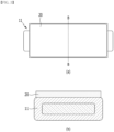
- Fig. 1 is a perspective view of a conventional battery module.
- Fig. 2 is a top view of a battery cell stack included in a conventional battery module.
- Fig. 3 (a) is a top view of the region A of Fig. 2 as viewed from above, and Fig. 3 (b) is a cross-sectional view taken along the cutting surface B-B of (a).
- the conventional battery module includes a battery cell stack 12 in which a plurality of battery cells 11 are stacked in one direction, module frames 30 and 40 for accommodating the battery cell stack 12, an end plate 15 for covering the front and rear surfaces of the battery cell stack 12.
- the module frames 30 and 40 include a lower frame 30 for covering the lower and both side surfaces of the battery cell stack 12, and an upper plate 40 for covering the upper surface of the battery cell stack 12.
- the battery cell stack 12 includes a fixing member 17 for fixing the plurality of battery cells 11 to each other, and the fixing member 17 is located at the central part and/or the end part of the battery cell stack 12. Further, a compression pad 20 is located between a pair of battery cells adjacent to each other in the battery cell stack 12.
- the compression pad 20 located in the conventional battery cell stack is in contact with the upper surface or the lower surface of the battery cells 11.
- the compression pad 20 can absorb the impact propagated to adjacent battery cells 11. Further, when the battery cell 11 ignites, the heat propagation speed can be delayed due to the thickness possessed by the compression pad 20.
- pressure and/or heat is applied to the compression pad 20. At this time, the compression rate of the conventional compression pad 20 appears differently in accordance with the position, and thus the physical properties of the compression pad 20 may be changed.
- a battery module comprising: a plurality of battery modules including a battery cell stack in which a plurality of battery cells are stacked, and a barrier layer interposed between battery cells adjacent to each other among the plurality of battery cells, wherein the barrier layer has a different thickness in accordance with the position.
- the thickness of the barrier layer may increase toward the edge with respect to the surface facing a body part of the battery cell.
- the barrier layer may include a first barrier part that covers the body part of the battery cell, and a second barrier part that extends from the first barrier part and covers a top part of the battery cell.
- a thickness of the first barrier part may be larger than a thickness of the second barrier part.
- the second barrier part may be formed of a flexible material.
- the top part of the battery cell may include a first region covered by the second barrier part and a second region not covered by the second barrier part.
- the barrier layer may further include a third barrier part that covers the end part of the battery cell around the electrode lead protruding from the battery cell.
- the barrier layer may be formed of a flame retardant member.
- the barrier layer may be formed of a silicon foam pad or a mica sheet.
- the barrier layer may include at least two or more, and at least two or more battery cells may be located between two adjacent barrier layers among the barrier layers.
- the barrier layer may cover one side of both surfaces of the battery cell, extend from an upper side of the barrier layer and cover a portion of the other side of the battery cell.
- the barrier layer may induce the direction of the flame generated in the battery cell due to the asymmetric structure.
- a battery pack comprising the above-mentioned battery module.
- the barrier layer formed between a pair of battery cells adjacent to each other in the battery cell stack functions as a flame retardant member, thereby capable of delaying the heat transfer speed between adjacent battery cells when a battery cell ignites.
- the barrier layer is applied not only to the body part of the battery cell but also to the top part and lead part of the battery cell extending therefrom, thereby capable of delaying the heat transfer speed into a battery cell in which no flame occurs by the cell external flame.
- the barrier layer is formed so as to have a different thickness for each location, thereby lowering the compressibility of the barrier layer during cell swelling to maximize the performance as a flame retardant member, and thus effectively delaying the heat propagation time between the battery cells.
- planar when referred to as “planar”, it means when a target portion is viewed from the upper side, and when referred to as “cross-sectional”, it means when a target portion is viewed from the side of a cross section cut vertically.
- Fig. 4 is a diagram showing a method of forming a battery cell stack according to a comparative example.
- the battery cells 11 in the step of stacking the battery cells 11, they can be stacked by interposing a compression pad 20 between battery cell 11 and battery cell 11 adjacent to each other. After stacking the compression pad 20, stacking of the battery cells 11 can be continuously performed again. At this time, the compression pad 20 may have a constant thickness. The compression pad 20 can play a role in preventing cell swirling and can delay heat propagation to some extent when the cell ignites.
- the battery cells 11 and the compression pad 20 are stacked to form a battery cell stack, and subsequently, subjected to a lead welding process and a module frame process to form a battery module.
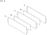
- Fig. 5 is a diagram showing a method of forming a battery cell stack included in a battery module according to an embodiment of the present disclosure.
- Fig. 6 is a perspective view showing one battery cell included in the battery cell stack of Fig. 5 .
- Fig. 7 is a front view showing a barrier layer surrounding one battery cell included in the battery cell stack of Fig. 5 .
- the battery cell stack included in the battery module is formed by stacking a plurality of battery cells 110, and includes a barrier layer 200 interposed between battery cells 110 adjacent to each other among the plurality of battery cells 110.
- the barrier layer 200 is formed of a flame retardant member.
- the barrier layer 200 may be formed of a silicon foam pad or a mica sheet.
- the battery module includes at least two barrier layers 200, and although not shown, at least two or more battery cells 110 may be located between two adjacent barrier layers 200 among the barrier layers 200.
- the battery cell 110 according to the embodiment of the present disclosure is preferably a pouch-type battery cell.
- the battery cell 110 according to the embodiment of the present disclosure has a structure in which two electrode leads 111 and 112 face each other and protrude from one end part 114a and the other end part 14b of the battery body 113, respectively.
- the battery cell 110 can be manufactured by adhering both end parts 114a and 114b of a battery case 114 and both side surfaces 114c connecting them in a state in which an electrode assembly (not shown) is accommodated in the battery case 114.
- the battery cell 110 has a total of three sealing parts 114sa, 114sb, 114sc, and the sealing parts 114sa, 114sb, 114sc has a structure being sealed by a method such as heat fusion, and the other side part may be formed of a connection part 115.
- a direction from end part 114a to end part 114b is defined as a longitudinal direction of the battery cell 110.
- a direction from one side part 114c, which connects between both end parts 114a and 114b, to the connection part 115 is defined as a width direction of the battery cell 110.
- connection part 115 is a region extending long along one edge of the battery cell 110, and a protrusion part 110p of the battery cell 110 can be formed at the end part of the connection part 115 and can protrude in a direction perpendicular to the direction in which the connection part 115 extends.
- the protrusion part 110p may be located between one of the sealing parts 114sa and 114sb of both end parts 114a and 114b of the battery case 114 and the connection part 115.
- the battery case 114 generally has a laminate structure of a resin layer/a metal thin film layer/a resin layer.
- a battery cell stack can be formed by attaching an adhesive member such as a cohesive-type adhesive such as a double-sided tape or a chemical adhesive bonded by chemical reaction during adhesion to the surface of the battery case.
- the battery cell stack 120 can be stacked in the y-axis direction.
- the barrier layer 200 may include a first barrier part 200a that covers the body part 110B of the battery cell 110, and a second barrier part 200b that extends from the first barrier part 200a and covers the top part 110T of the battery cell 110.
- the body part 110B of the battery cell 110 refers to one surface of the battery cell 110 facing the y-axis direction, which is the direction in which the battery cells 110 are stacked, and the top part 110T of the battery cell 110 may be a portion corresponding to one side part 114c connecting both end parts 114a and 114b of the battery case 114.
- the top part 110T of the battery cell 110 may refer to the upper end part based on the width direction of the battery cell 110.
- the thickness of the first barrier part 200a may be larger than the thickness of the second barrier part 200b.
- the second barrier part 200b can be formed of a flexible material.
- the first barrier part 200a can be formed to be relatively thick, thereby increasing the flame retardant performance of interrupting heat propagation between adjacent battery cells 110, and due to the second barrier part 200b formed to be relatively thin, the occurrence of a gap between the module frame accommodating the battery cell stack and the upper end of the battery cell 110 can be minimized.
- the second barrier part 200b is formed of a flexible material, so that the double-side folding structure of the upper end of the battery cell 110 can be closely covered.
- the barrier layer 200 may further include a third barrier part 200c covering an end part of the battery cell 110 around the electrode leads 111 and 112 protruding from the battery cell 110.
- An opening 200A through which the electrode leads 111 and 112 pass may be formed in the third barrier part 200c.
- Fig. 8 is a perspective view showing a battery cell stack formed by combining the battery cells of Fig. 5 .
- the battery module including the battery cell stack includes a first barrier part 200a, so that heat conduction from the ignited battery cell 110 to the adjacent battery cell 110 can be interrupted when the cell ignites.
- the battery module in addition to the body part 110B of the battery cell 110, the battery module includes a second barrier part 200b covering the top part 110T and a third barrier part 200c covering the end part of the battery cell 110 around the electrode leads 111 and 112, thereby capable of cancelling the effect of heat conduction to the battery cell 110 in which no flame occurs by the external flame.
- a first barrier part 200a covering the top part 110T
- a third barrier part 200c covering the end part of the battery cell 110 around the electrode leads 111 and 112
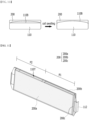
- Fig. 9 is a plan view showing a barrier layer formed on a battery cell body part included in a battery module according to another embodiment of the present disclosure.
- Fig. 10 is a cross-sectional view taken along the cutting line P-P of Fig. 9 .
- the barrier layer 200 may have a different thickness in accordance with the position. Specifically, the thickness of the barrier layer 200 may increase toward the edge with respect to the surface facing the body portion 110B of the battery cell 110.
- the cell swelling phenomenon caused by charging of the battery cell 110 has not been considered, and the compression pad 20 described with reference to Fig. 4 having the same thickness in all regions has been applied as a barrier layer.
- the compression pad is compressed due to the cell swelling phenomenon, the physical properties of the barrier layer can be changed.
- the thickness of the barrier layer 200 can be differently applied for each region in consideration of the cell swelling phenomenon.
- the compressibility of the barrier layer 200 can be lowered to maximize the performance of the flame retardant member, thereby effectively delaying the heat propagation time between the battery cells 110.
- the description of the battery cell 110 described with reference to Figs. 5 to 8 can also be applied to the embodiment of the present disclosure.
- the thickness of the first barrier part 200a described with reference to Figs. 5 to 8 can be formed differently in accordance with the position.
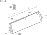
- Fig. 11 is a perspective view showing a barrier layer covering a battery cell according to another embodiment of the present disclosure.
- Fig. 12 is a perspective view of the battery cell of Fig. 11 as viewed from the surface of opposite side by rotating 180 degrees.
- Fig. 13 is a perspective view showing a battery cell stack formed by using the battery cell and a barrier layer of Fig. 11 .
- Fig. 14 is a perspective view showing a path through which a flame is discharged when the battery cell ignites according to the embodiment of Fig. 11 .
- the barrier layer 200 can cover one side of both surfaces of the battery cell 110, extend from the upper side of the barrier layer 200 and cover a portion of the other side of the battery cell 110.
- the top part 110T of the battery cell 110 may include a first region P1 covered by the second barrier part 200b and a second region P2 not covered by the second barrier part 200b.
- the third barrier part 200c may be formed only at one end of the battery cell 110 adjacent to the first region P1.
- the first region P1 may be a partial region in the longitudinal direction covered by the second barrier part 200b of the top part 110T of the battery cell 110.
- the first region P1 and the second region P2 may be located at different positions in the longitudinal direction of the battery cell 110.
- the first region P1 may be adjacent to one end of the battery cell 110, and the second region P2 may be adjacent to the other end of the battery cell 110.
- the barrier layer 200 may induce the direction of the flame generated in the battery cell 110 due to the asymmetric structure. For example, by forming the top part 110T of the battery cell 110 including the first region P1 and the second region P2, the flame may be induced in the left direction of the battery cell 110 as shown in Fig. 14 .
- the thickness of the first barrier part 200a may be larger than the thickness of the second barrier part 200b.
- the second barrier part 200b may be formed of a flexible material.
- the first barrier portion 200a is formed to be relatively thick, thereby capable of increasing the flame retardant performance of interrupting heat propagation between adjacent battery cells 110, and due to the second barrier part 200b formed to be relatively thin, the occurrence of a gap between the upper end of the battery cell 110 and the module frame accommodating the battery cell stack can be minimized.
- the second barrier part 200b can be formed of a flexible material so as to closely cover the double-side folding structure of the upper end of the battery cell 110. If there is a gap between the second barrier part 200b covering the upper end of the battery cell 110 and the upper end of the module frame, induction of the flame direction may not be performed well.
- the battery cell stack 120 may include a plurality of battery cells 110 covered by the barrier layer 200. Because it is difficult to know which of the battery cells 110 is ignited among the stacked battery cells 110, a plurality of battery cells 110 covered by the barrier layer 200 can be applied to design flame induction and heat propagation interruption.
- one or more of the battery modules according to embodiments of the present disclosure can be packaged in a pack case to form a battery pack.
- the above-mentioned battery module and a battery pack including the same may be applied to various devices. These devices can be applied to vehicle means such as an electric bicycle, an electric vehicle, a hybrid vehicle, but the present disclosure is not limited thereto and can be applied to various devices that can use the battery module and the battery pack including the same, which also belongs to the scope of the present disclosure.
- battery cell 110B body part 110T: top part 120: battery cell stack 200: barrier layer 200a: first barrier part 200b: second barrier part 200c: third barrier part
Landscapes
- Chemical & Material Sciences (AREA)
- Chemical Kinetics & Catalysis (AREA)
- Electrochemistry (AREA)
- General Chemical & Material Sciences (AREA)
- Engineering & Computer Science (AREA)
- Manufacturing & Machinery (AREA)
- Health & Medical Sciences (AREA)
- Public Health (AREA)
- Business, Economics & Management (AREA)
- Emergency Management (AREA)
- Battery Mounting, Suspending (AREA)
- Secondary Cells (AREA)
Abstract
Description
- This application claims the benefit of
Korean Patent Application No. 10-2020-0137479 filed on October 27, 2020 - The present disclosure relates to a battery module and a battery pack including the same, and more particularly, to a battery module that effectively delays a heat propagation speed between battery cells, and a battery pack including the same.
- As technology development and demands for mobile devices increase, the demand for batteries as energy sources is rapidly increasing. In particular, a secondary battery has attracted considerable attention as an energy source for power-driven devices, such as an electric bicycle, an electric vehicle, and a hybrid electric vehicle, as well as an energy source for mobile devices, such as a mobile phone, a digital camera, a laptop computer and a wearable device.
- The middle or large-sized battery module is preferably manufactured so as to have as small a size and weight as possible. For this reason, a prismatic battery, a pouch-type battery or the like, which can be stacked with high integration and has a small weight to capacity ratio, is usually used as a battery cell of the middle or large-sized battery module. Meanwhile, in order to protect the battery cell stack from external impact, heat or vibration, the battery module may include a module frame in which a front surface and rear surface are opened to house the battery cell stack in an internal space.
-
Fig. 1 is a perspective view of a conventional battery module.Fig. 2 is a top view of a battery cell stack included in a conventional battery module.Fig. 3 (a) is a top view of the region A ofFig. 2 as viewed from above, andFig. 3 (b) is a cross-sectional view taken along the cutting surface B-B of (a). - Referring to
Figs. 1 and2 , the conventional battery module includes abattery cell stack 12 in which a plurality ofbattery cells 11 are stacked in one direction,module frames battery cell stack 12, anend plate 15 for covering the front and rear surfaces of thebattery cell stack 12. Themodule frames lower frame 30 for covering the lower and both side surfaces of thebattery cell stack 12, and anupper plate 40 for covering the upper surface of thebattery cell stack 12. - In addition, the
battery cell stack 12 includes afixing member 17 for fixing the plurality ofbattery cells 11 to each other, and thefixing member 17 is located at the central part and/or the end part of thebattery cell stack 12. Further, acompression pad 20 is located between a pair of battery cells adjacent to each other in thebattery cell stack 12. - Referring to
Figs. 2 and3 , thecompression pad 20 located in the conventional battery cell stack is in contact with the upper surface or the lower surface of thebattery cells 11. Thecompression pad 20 can absorb the impact propagated toadjacent battery cells 11. Further, when thebattery cell 11 ignites, the heat propagation speed can be delayed due to the thickness possessed by thecompression pad 20. However, when a swelling phenomenon occurs in the charging/discharging process of thebattery cells 11, pressure and/or heat is applied to thecompression pad 20. At this time, the compression rate of theconventional compression pad 20 appears differently in accordance with the position, and thus the physical properties of thecompression pad 20 may be changed. In addition, when thebattery cells 110 ignite, secondary cell ignition may occur due to heat conduction betweenadjacent battery cells 11 and external heat conduction caused by flames generated in thebattery cells 11. For this reason, it is difficult to sufficiently perform the role of delaying the heat propagation speed by using only theconventional compression pad 20. Therefore, unlike the conventional one, there is a need to develop a battery module that effectively delays the heat propagation speed between battery cells even when a swelling phenomenon occurs. - It is an object of the present disclosure to provide a battery module that effectively delays a heat propagation speed between battery cells, and a battery pack including the same.
- However, the technical problem to be solved by embodiments of the present disclosure is not limited to the above-described problems, and can be variously expanded within the scope of the technical idea included in the present disclosure.
- According to one embodiment of the present disclosure, there is provided a battery module comprising: a plurality of battery modules including a battery cell stack in which a plurality of battery cells are stacked, and a barrier layer interposed between battery cells adjacent to each other among the plurality of battery cells, wherein the barrier layer has a different thickness in accordance with the position.
- The thickness of the barrier layer may increase toward the edge with respect to the surface facing a body part of the battery cell.
- The barrier layer may include a first barrier part that covers the body part of the battery cell, and a second barrier part that extends from the first barrier part and covers a top part of the battery cell.
- A thickness of the first barrier part may be larger than a thickness of the second barrier part.
- The second barrier part may be formed of a flexible material.
- The top part of the battery cell may include a first region covered by the second barrier part and a second region not covered by the second barrier part.
- The barrier layer may further include a third barrier part that covers the end part of the battery cell around the electrode lead protruding from the battery cell.
- An opening through which the electrode lead passes may be formed in the third barrier part. The barrier layer may be formed of a flame retardant member.
- The barrier layer may be formed of a silicon foam pad or a mica sheet.
- The barrier layer may include at least two or more, and at least two or more battery cells may be located between two adjacent barrier layers among the barrier layers.
- The barrier layer may cover one side of both surfaces of the battery cell, extend from an upper side of the barrier layer and cover a portion of the other side of the battery cell.
- The barrier layer may induce the direction of the flame generated in the battery cell due to the asymmetric structure.
- According to another embodiment of the present disclosure, there is provided a battery pack comprising the above-mentioned battery module.
- According to embodiments of the present disclosure, the barrier layer formed between a pair of battery cells adjacent to each other in the battery cell stack functions as a flame retardant member, thereby capable of delaying the heat transfer speed between adjacent battery cells when a battery cell ignites.
- Further, the barrier layer is applied not only to the body part of the battery cell but also to the top part and lead part of the battery cell extending therefrom, thereby capable of delaying the heat transfer speed into a battery cell in which no flame occurs by the cell external flame.
- In addition, the barrier layer is formed so as to have a different thickness for each location, thereby lowering the compressibility of the barrier layer during cell swelling to maximize the performance as a flame retardant member, and thus effectively delaying the heat propagation time between the battery cells.
- The effects of the present disclosure are not limited to the effects mentioned above and additional other effects not described above will be clearly understood from the description of the appended claims by those skilled in the art.
-
-
Fig. 1 is a perspective view of a conventional battery module; -
Fig. 2 is a top view of a battery cell stack contained in a conventional battery module. -
Fig. 3 (a) is a top view of the region A ofFig. 2 as viewed from above, andFig. 3 (b) is a cross-sectional view taken along the cutting surface B-B of (a); -
Fig. 4 is a diagram showing a method of forming a battery cell stack according to a comparative example; -
Fig. 5 is a diagram showing a method of forming a battery cell stack included in a battery module according to an embodiment of the present disclosure; -
Fig. 6 is a perspective view showing one battery cell included in the battery cell stack ofFig. 5 ; -
Fig. 7 is a front view showing a barrier layer surrounding one battery cell included in the battery cell stack ofFig. 5 ; -
Fig. 8 is a perspective view showing a battery cell stack formed by combining the battery cells ofFig. 5 ; -
Fig. 9 is a plan view showing a barrier layer formed on a battery cell body part included in a battery module according to another embodiment of the present disclosure; -
Fig. 10 is a cross-sectional view taken along the cutting line P-P ofFig. 9 ; -
Fig. 11 is a perspective view showing a barrier layer covering a battery cell according to another embodiment of the present disclosure; -
Fig. 12 is a perspective view of the battery cell ofFig. 11 as viewed from the surface of opposite side by rotating 180 degrees; -
Fig. 13 is a perspective view showing a battery cell stack formed by using the battery cell and a barrier layer ofFig. 11 ; and -
Fig. 14 is a perspective view showing a path through which a flame is discharged when the battery cell ignites according to the embodiment ofFig. 11 . - Hereinafter, various embodiments of the present disclosure will be described in detail with reference to the accompanying drawings so that those skilled in the art can easily implement them. The present disclosure may be modified in various different ways, and is not limited to the embodiments set forth herein.
- Portions that are irrelevant to the description will be omitted to clearly describe the present disclosure, and like reference numerals designate like elements throughout the specification.
- Further, in the figures, the size and thickness of each element are arbitrarily illustrated for convenience of description, and the present disclosure is not necessarily limited to those illustrated in the figures. In the figures, the thickness of layers, regions, etc. are exaggerated for clarity. In the figures, for convenience of description, the thicknesses of some layers and regions are shown to be exaggerated.
- In addition, it will be understood that when an element such as a layer, film, region, or plate is referred to as being "on" or "above" another element, it can be directly on the other element or intervening elements may also be present. In contrast, when an element is referred to as being "directly on" another element, it means that other intervening elements are not present. Further, the word "on" or "above" means disposed on or below a reference portion, and does not necessarily mean being disposed on the upper end of the reference portion toward the opposite direction of gravity. Further, throughout the specification, when a portion is referred to as "including" a certain component, it means that the portion can further include other components, without excluding the other components, unless otherwise stated. Further, throughout the specification, when referred to as "planar", it means when a target portion is viewed from the upper side, and when referred to as "cross-sectional", it means when a target portion is viewed from the side of a cross section cut vertically.
-
Fig. 4 is a diagram showing a method of forming a battery cell stack according to a comparative example. - Referring to
Fig. 4 , in the step of stacking thebattery cells 11, they can be stacked by interposing acompression pad 20 betweenbattery cell 11 andbattery cell 11 adjacent to each other. After stacking thecompression pad 20, stacking of thebattery cells 11 can be continuously performed again. At this time, thecompression pad 20 may have a constant thickness. Thecompression pad 20 can play a role in preventing cell swirling and can delay heat propagation to some extent when the cell ignites. Thebattery cells 11 and thecompression pad 20 are stacked to form a battery cell stack, and subsequently, subjected to a lead welding process and a module frame process to form a battery module. -
Fig. 5 is a diagram showing a method of forming a battery cell stack included in a battery module according to an embodiment of the present disclosure.Fig. 6 is a perspective view showing one battery cell included in the battery cell stack ofFig. 5 .Fig. 7 is a front view showing a barrier layer surrounding one battery cell included in the battery cell stack ofFig. 5 . - Referring to
Fig. 5 , the battery cell stack included in the battery module according to the embodiment of the present disclosure is formed by stacking a plurality ofbattery cells 110, and includes abarrier layer 200 interposed betweenbattery cells 110 adjacent to each other among the plurality ofbattery cells 110. Thebarrier layer 200 is formed of a flame retardant member. At this time, thebarrier layer 200 may be formed of a silicon foam pad or a mica sheet. The battery module includes at least twobarrier layers 200, and although not shown, at least two ormore battery cells 110 may be located between two adjacent barrier layers 200 among the barrier layers 200. - The
battery cell 110 according to the embodiment of the present disclosure is preferably a pouch-type battery cell. For example, referring toFig. 6 , thebattery cell 110 according to the embodiment of the present disclosure has a structure in which two electrode leads 111 and 112 face each other and protrude from oneend part 114a and the other end part 14b of thebattery body 113, respectively. Thebattery cell 110 can be manufactured by adhering bothend parts battery case 114 and both side surfaces 114c connecting them in a state in which an electrode assembly (not shown) is accommodated in thebattery case 114. In other words, thebattery cell 110 according to the embodiment of the present disclosure has a total of three sealing parts 114sa, 114sb, 114sc, and the sealing parts 114sa, 114sb, 114sc has a structure being sealed by a method such as heat fusion, and the other side part may be formed of aconnection part 115. A direction fromend part 114a to endpart 114b is defined as a longitudinal direction of thebattery cell 110. A direction from oneside part 114c, which connects between bothend parts connection part 115 is defined as a width direction of thebattery cell 110. - The
connection part 115 is a region extending long along one edge of thebattery cell 110, and aprotrusion part 110p of thebattery cell 110 can be formed at the end part of theconnection part 115 and can protrude in a direction perpendicular to the direction in which theconnection part 115 extends. Theprotrusion part 110p may be located between one of the sealing parts 114sa and 114sb of bothend parts battery case 114 and theconnection part 115. - The
battery case 114 generally has a laminate structure of a resin layer/a metal thin film layer/a resin layer. For example, when the surface of the battery case is formed of an O (oriented)-nylon layer, it tends to slide easily due to external impact when stacking a plurality of battery cells to form a medium or large-sized battery module. Therefore, in order to prevent this problem and maintain a stable stacked structure of battery cells, a battery cell stack can be formed by attaching an adhesive member such as a cohesive-type adhesive such as a double-sided tape or a chemical adhesive bonded by chemical reaction during adhesion to the surface of the battery case. In the embodiment of the present disclosure, thebattery cell stack 120 can be stacked in the y-axis direction. - Referring to
Figs. 5 to 7 , thebarrier layer 200 according to the embodiment of the present disclosure may include afirst barrier part 200a that covers thebody part 110B of thebattery cell 110, and asecond barrier part 200b that extends from thefirst barrier part 200a and covers thetop part 110T of thebattery cell 110. Thebody part 110B of thebattery cell 110 refers to one surface of thebattery cell 110 facing the y-axis direction, which is the direction in which thebattery cells 110 are stacked, and thetop part 110T of thebattery cell 110 may be a portion corresponding to oneside part 114c connecting bothend parts battery case 114. In other words, thetop part 110T of thebattery cell 110 may refer to the upper end part based on the width direction of thebattery cell 110. - At this time, the thickness of the
first barrier part 200a may be larger than the thickness of thesecond barrier part 200b. Thesecond barrier part 200b can be formed of a flexible material. Thefirst barrier part 200a can be formed to be relatively thick, thereby increasing the flame retardant performance of interrupting heat propagation betweenadjacent battery cells 110, and due to thesecond barrier part 200b formed to be relatively thin, the occurrence of a gap between the module frame accommodating the battery cell stack and the upper end of thebattery cell 110 can be minimized. In addition, thesecond barrier part 200b is formed of a flexible material, so that the double-side folding structure of the upper end of thebattery cell 110 can be closely covered. - Referring to
Fig. 7 , thebarrier layer 200 according to the embodiment of the present disclosure may further include athird barrier part 200c covering an end part of thebattery cell 110 around the electrode leads 111 and 112 protruding from thebattery cell 110. Anopening 200A through which the electrode leads 111 and 112 pass may be formed in thethird barrier part 200c. -
Fig. 8 is a perspective view showing a battery cell stack formed by combining the battery cells ofFig. 5 . - Referring to
Figs. 5 to 8 , the battery module including the battery cell stack according to the embodiment of the present disclosure includes afirst barrier part 200a, so that heat conduction from the ignitedbattery cell 110 to theadjacent battery cell 110 can be interrupted when the cell ignites. In addition, in addition to thebody part 110B of thebattery cell 110, the battery module includes asecond barrier part 200b covering thetop part 110T and athird barrier part 200c covering the end part of thebattery cell 110 around the electrode leads 111 and 112, thereby capable of cancelling the effect of heat conduction to thebattery cell 110 in which no flame occurs by the external flame. For example, referring toFig. 8 , when ignition occurs in thefirst battery cell 110a, heat conduction due to an external flame can be cancelled from thesecond battery cell 110b to which thebarrier layer 200 is applied. -
Fig. 9 is a plan view showing a barrier layer formed on a battery cell body part included in a battery module according to another embodiment of the present disclosure.Fig. 10 is a cross-sectional view taken along the cutting line P-P ofFig. 9 . - Referring to
Figs. 9 and10 thebarrier layer 200 according to the embodiment of the present disclosure may have a different thickness in accordance with the position. Specifically, the thickness of thebarrier layer 200 may increase toward the edge with respect to the surface facing thebody portion 110B of thebattery cell 110. Conventionally, the cell swelling phenomenon caused by charging of thebattery cell 110 has not been considered, and thecompression pad 20 described with reference toFig. 4 having the same thickness in all regions has been applied as a barrier layer. When the compression pad is compressed due to the cell swelling phenomenon, the physical properties of the barrier layer can be changed. On the contrary, according to the embodiment of the present disclosure, the thickness of thebarrier layer 200 can be differently applied for each region in consideration of the cell swelling phenomenon. Therefore, during the cell swelling phenomenon, the compressibility of thebarrier layer 200 can be lowered to maximize the performance of the flame retardant member, thereby effectively delaying the heat propagation time between thebattery cells 110. The description of thebattery cell 110 described with reference toFigs. 5 to 8 can also be applied to the embodiment of the present disclosure. For example, the thickness of thefirst barrier part 200a described with reference toFigs. 5 to 8 can be formed differently in accordance with the position. -
Fig. 11 is a perspective view showing a barrier layer covering a battery cell according to another embodiment of the present disclosure.Fig. 12 is a perspective view of the battery cell ofFig. 11 as viewed from the surface of opposite side by rotating 180 degrees.Fig. 13 is a perspective view showing a battery cell stack formed by using the battery cell and a barrier layer ofFig. 11 .Fig. 14 is a perspective view showing a path through which a flame is discharged when the battery cell ignites according to the embodiment ofFig. 11 . - Referring to
Figs. 11 and12 , thebarrier layer 200 can cover one side of both surfaces of thebattery cell 110, extend from the upper side of thebarrier layer 200 and cover a portion of the other side of thebattery cell 110. At this time, thetop part 110T of thebattery cell 110 may include a first region P1 covered by thesecond barrier part 200b and a second region P2 not covered by thesecond barrier part 200b. At this time, thethird barrier part 200c may be formed only at one end of thebattery cell 110 adjacent to the first region P1. - Meanwhile, the first region P1 may be a partial region in the longitudinal direction covered by the
second barrier part 200b of thetop part 110T of thebattery cell 110. The first region P1 and the second region P2 may be located at different positions in the longitudinal direction of thebattery cell 110. The first region P1 may be adjacent to one end of thebattery cell 110, and the second region P2 may be adjacent to the other end of thebattery cell 110. - The
barrier layer 200 according to the embodiment of the present disclosure may induce the direction of the flame generated in thebattery cell 110 due to the asymmetric structure. For example, by forming thetop part 110T of thebattery cell 110 including the first region P1 and the second region P2, the flame may be induced in the left direction of thebattery cell 110 as shown inFig. 14 . - As described in the embodiments of
Figs. 5 to 7 , the thickness of thefirst barrier part 200a may be larger than the thickness of thesecond barrier part 200b. Thesecond barrier part 200b may be formed of a flexible material. Thefirst barrier portion 200a is formed to be relatively thick, thereby capable of increasing the flame retardant performance of interrupting heat propagation betweenadjacent battery cells 110, and due to thesecond barrier part 200b formed to be relatively thin, the occurrence of a gap between the upper end of thebattery cell 110 and the module frame accommodating the battery cell stack can be minimized. In addition, thesecond barrier part 200b can be formed of a flexible material so as to closely cover the double-side folding structure of the upper end of thebattery cell 110. If there is a gap between thesecond barrier part 200b covering the upper end of thebattery cell 110 and the upper end of the module frame, induction of the flame direction may not be performed well. - Referring to
Fig. 13 , thebattery cell stack 120 according to the embodiment of the present disclosure may include a plurality ofbattery cells 110 covered by thebarrier layer 200. Because it is difficult to know which of thebattery cells 110 is ignited among the stackedbattery cells 110, a plurality ofbattery cells 110 covered by thebarrier layer 200 can be applied to design flame induction and heat propagation interruption. - Meanwhile, one or more of the battery modules according to embodiments of the present disclosure can be packaged in a pack case to form a battery pack.
- The above-mentioned battery module and a battery pack including the same may be applied to various devices. These devices can be applied to vehicle means such as an electric bicycle, an electric vehicle, a hybrid vehicle, but the present disclosure is not limited thereto and can be applied to various devices that can use the battery module and the battery pack including the same, which also belongs to the scope of the present disclosure.
- Although the preferred embodiments of the present disclosure have been described in detail above, the scope of the present disclosure is not limited thereto, and various modifications and improvements made by those skilled in the art using the basic concepts of the present disclosure defined in the following claims also belong to the scope of rights.
-
110: battery cell 110B: body part 110T: top part 120: battery cell stack 200: barrier layer 200a: first barrier part 200b: second barrier part 200c: third barrier part
Claims (14)
- A battery module comprising:a battery cell stack in which a plurality of battery cells are stacked, anda barrier layer interposed between battery cells adjacent to each other among the plurality of battery cells,wherein the barrier layer has a different thickness in accordance with the position.
- The battery module of claim 1, wherein:
the thickness of the barrier layer increases toward the edge with respect to the surface facing a body part of the battery cell. - The battery module of claim 1, wherein:
the barrier layer comprises a first barrier part that covers the body part of the battery cell, and a second barrier part that extends from the first barrier part and covers a top part of the battery cell. - The battery module of claim 3, wherein:
a thickness of the first barrier part is larger than a thickness of the second barrier part. - The battery module of claim 4, wherein:
the second barrier part is formed of a flexible material. - The battery module of claim 5, wherein:
the top part of the battery cell comprises a first region covered by the second barrier part and a second region not covered by the second barrier part. - The battery module of claim 3, wherein:
the barrier layer further comprises a third barrier part that covers the end part of the battery cell around the electrode lead protruding from the battery cell. - The battery module of claim 7, wherein:
an opening through which the electrode lead passes is formed in the third barrier part. - The battery module of claim 1, wherein:
the barrier layer is formed of a flame retardant member. - The battery module of claim 9, wherein:
the barrier layer is formed of a silicon foam pad or a mica sheet. - The battery module of claim 1, wherein:
the barrier layer comprises at least two or more, and at least two or more battery cells are located between two adjacent barrier layers among the barrier layers. - The battery module of claim 1, wherein:
the barrier layer covers one side of both surfaces of the battery cell, extends from an upper side of the barrier layer and covers a portion of the other side of the battery cell. - The battery module of claim 12, wherein:
the barrier layer induces the direction of the flame generated in the battery cell due to the asymmetric structure. - A battery pack comprising the battery module of claim 1.
Applications Claiming Priority (2)
| Application Number | Priority Date | Filing Date | Title |
|---|---|---|---|
| KR1020200137479A KR20220053251A (en) | 2020-10-22 | 2020-10-22 | Battery module and battery pack including the same |
| PCT/KR2021/013263 WO2022085969A1 (en) | 2020-10-22 | 2021-09-28 | Battery module and battery pack comprising same |
Publications (2)
| Publication Number | Publication Date |
|---|---|
| EP4181289A1 true EP4181289A1 (en) | 2023-05-17 |
| EP4181289A4 EP4181289A4 (en) | 2024-07-31 |
Family
ID=81194729
Family Applications (1)
| Application Number | Title | Priority Date | Filing Date |
|---|---|---|---|
| EP21883041.2A Pending EP4181289A4 (en) | 2020-10-22 | 2021-09-28 | BATTERY MODULE AND BATTERY PACK |
Country Status (6)
| Country | Link |
|---|---|
| US (1) | US20230275316A1 (en) |
| EP (1) | EP4181289A4 (en) |
| JP (2) | JP7644218B2 (en) |
| KR (1) | KR20220053251A (en) |
| CN (2) | CN114388973A (en) |
| WO (1) | WO2022085969A1 (en) |
Families Citing this family (3)
| Publication number | Priority date | Publication date | Assignee | Title |
|---|---|---|---|---|
| KR20220053251A (en) * | 2020-10-22 | 2022-04-29 | 주식회사 엘지에너지솔루션 | Battery module and battery pack including the same |
| KR20240045453A (en) * | 2022-09-29 | 2024-04-08 | 주식회사 엘지에너지솔루션 | Battery cell and battery module including the same |
| KR102673481B1 (en) * | 2023-06-01 | 2024-06-12 | 나노팀 주식회사 | Sheet having heat shield function using battery |
Family Cites Families (16)
| Publication number | Priority date | Publication date | Assignee | Title |
|---|---|---|---|---|
| JP2008166191A (en) * | 2006-12-28 | 2008-07-17 | Sanyo Electric Co Ltd | Battery pack |
| JP2012033464A (en) * | 2010-07-02 | 2012-02-16 | Sanyo Electric Co Ltd | Battery pack |
| JP5590067B2 (en) * | 2012-04-19 | 2014-09-17 | トヨタ自動車株式会社 | Charge / discharge device |
| JP6073583B2 (en) * | 2012-06-28 | 2017-02-01 | 三洋電機株式会社 | Power supply device, vehicle including this power supply device, and power storage device |
| KR101730961B1 (en) * | 2013-01-04 | 2017-04-27 | 삼성에스디아이 주식회사 | Battery module having heat insulating member |
| KR102044409B1 (en) * | 2015-05-14 | 2019-11-13 | 주식회사 엘지화학 | Battery pack including cartridge for secondary battery |
| JP2020161211A (en) * | 2017-07-27 | 2020-10-01 | 三洋電機株式会社 | Battery module, and vehicle equipped with the same |
| DE102018000421A1 (en) * | 2017-12-21 | 2019-06-27 | H.K.O. Isolier- Und Textiltechnik Gmbh | Multilayer thermal insulation element for batteries |
| KR102282482B1 (en) * | 2018-02-06 | 2021-07-26 | 주식회사 엘지에너지솔루션 | Battery module and battery pack including the same |
| JP6764023B2 (en) * | 2018-02-20 | 2020-09-30 | 積水化学工業株式会社 | Refractory resin compositions, refractory sheets, refractory laminates, and batteries |
| JP7063744B2 (en) * | 2018-06-27 | 2022-05-09 | 住友理工株式会社 | Cushioning sheet for battery module |
| KR102703855B1 (en) * | 2018-08-21 | 2024-09-05 | 에스케이온 주식회사 | Battery module and Manufacturing method of the same |
| JP2020145149A (en) * | 2019-03-08 | 2020-09-10 | 株式会社Gsユアサ | Power storage device |
| KR102149439B1 (en) * | 2020-03-25 | 2020-08-31 | 주식회사 지에프아이 | Battery pack equipped with fire extiguishing film containing fire extiguishing micro―capsule |
| CN211789178U (en) * | 2020-04-22 | 2020-10-27 | 淮安骏盛新能源科技有限公司 | Lithium battery thermal runaway protector |
| KR20220053251A (en) * | 2020-10-22 | 2022-04-29 | 주식회사 엘지에너지솔루션 | Battery module and battery pack including the same |
-
2020
- 2020-10-22 KR KR1020200137479A patent/KR20220053251A/en active Pending
-
2021
- 2021-09-28 EP EP21883041.2A patent/EP4181289A4/en active Pending
- 2021-09-28 US US18/017,996 patent/US20230275316A1/en active Pending
- 2021-09-28 JP JP2023504077A patent/JP7644218B2/en active Active
- 2021-09-28 WO PCT/KR2021/013263 patent/WO2022085969A1/en not_active Ceased
- 2021-10-18 CN CN202111210334.8A patent/CN114388973A/en active Pending
- 2021-10-18 CN CN202122500715.1U patent/CN216671822U/en active Active
-
2025
- 2025-02-27 JP JP2025030462A patent/JP2025074174A/en active Pending
Also Published As
| Publication number | Publication date |
|---|---|
| JP2025074174A (en) | 2025-05-13 |
| CN216671822U (en) | 2022-06-03 |
| EP4181289A4 (en) | 2024-07-31 |
| US20230275316A1 (en) | 2023-08-31 |
| CN114388973A (en) | 2022-04-22 |
| JP2023534822A (en) | 2023-08-14 |
| WO2022085969A1 (en) | 2022-04-28 |
| KR20220053251A (en) | 2022-04-29 |
| JP7644218B2 (en) | 2025-03-11 |
Similar Documents
| Publication | Publication Date | Title |
|---|---|---|
| US12531266B2 (en) | Battery module and battery pack including the same | |
| US12614764B2 (en) | Battery module and battery pack including the same | |
| EP4181289A1 (en) | Battery module and battery pack comprising same | |
| JP2025074175A (en) | Battery module and battery pack including same | |
| US12573712B2 (en) | Battery module and battery pack including the same | |
| EP4266467B1 (en) | Battery module and battery pack including same | |
| JP7791313B2 (en) | Battery Module | |
| EP4131617A1 (en) | Battery module and battery pack including same | |
| EP4181290A1 (en) | Battery module and battery pack including same | |
| KR102961148B1 (en) | Battery module and battery pack including the same | |
| KR20230064246A (en) | Battery module and battery pack including the same | |
| KR20220080693A (en) | Battery module and battery pack including the same | |
| CN118556322A (en) | Battery module |
Legal Events
| Date | Code | Title | Description |
|---|---|---|---|
| STAA | Information on the status of an ep patent application or granted ep patent |
Free format text: STATUS: THE INTERNATIONAL PUBLICATION HAS BEEN MADE |
|
| PUAI | Public reference made under article 153(3) epc to a published international application that has entered the european phase |
Free format text: ORIGINAL CODE: 0009012 |
|
| STAA | Information on the status of an ep patent application or granted ep patent |
Free format text: STATUS: REQUEST FOR EXAMINATION WAS MADE |
|
| 17P | Request for examination filed |
Effective date: 20230208 |
|
| AK | Designated contracting states |
Kind code of ref document: A1 Designated state(s): AL AT BE BG CH CY CZ DE DK EE ES FI FR GB GR HR HU IE IS IT LI LT LU LV MC MK MT NL NO PL PT RO RS SE SI SK SM TR |
|
| DAV | Request for validation of the european patent (deleted) | ||
| DAX | Request for extension of the european patent (deleted) | ||
| REG | Reference to a national code |
Ref country code: DE Ref legal event code: R079 Free format text: PREVIOUS MAIN CLASS: H01M0050240000 Ipc: H01M0010613000 |
|
| A4 | Supplementary search report drawn up and despatched |
Effective date: 20240701 |
|
| RIC1 | Information provided on ipc code assigned before grant |
Ipc: A62C 3/16 20060101ALN20240625BHEP Ipc: H01M 50/383 20210101ALI20240625BHEP Ipc: H01M 50/211 20210101ALI20240625BHEP Ipc: H01M 50/291 20210101ALI20240625BHEP Ipc: H01M 50/293 20210101ALI20240625BHEP Ipc: H01M 10/658 20140101ALI20240625BHEP Ipc: H01M 10/613 20140101AFI20240625BHEP |
|
| STAA | Information on the status of an ep patent application or granted ep patent |
Free format text: STATUS: EXAMINATION IS IN PROGRESS |
|
| 17Q | First examination report despatched |
Effective date: 20250214 |