EP4180924A1 - Virtual reality / augmented reality handheld controller sensing - Google Patents
Virtual reality / augmented reality handheld controller sensing Download PDFInfo
- Publication number
- EP4180924A1 EP4180924A1 EP23150973.8A EP23150973A EP4180924A1 EP 4180924 A1 EP4180924 A1 EP 4180924A1 EP 23150973 A EP23150973 A EP 23150973A EP 4180924 A1 EP4180924 A1 EP 4180924A1
- Authority
- EP
- European Patent Office
- Prior art keywords
- sensors
- sensor
- user
- force
- sensor data
- Prior art date
- Legal status (The legal status is an assumption and is not a legal conclusion. Google has not performed a legal analysis and makes no representation as to the accuracy of the status listed.)
- Pending
Links
Images




Classifications
-
- G—PHYSICS
- G06—COMPUTING OR CALCULATING; COUNTING
- G06F—ELECTRIC DIGITAL DATA PROCESSING
- G06F3/00—Input arrangements for transferring data to be processed into a form capable of being handled by the computer; Output arrangements for transferring data from processing unit to output unit, e.g. interface arrangements
- G06F3/01—Input arrangements or combined input and output arrangements for interaction between user and computer
- G06F3/03—Arrangements for converting the position or the displacement of a member into a coded form
- G06F3/041—Digitisers, e.g. for touch screens or touch pads, characterised by the transducing means
- G06F3/0414—Digitisers, e.g. for touch screens or touch pads, characterised by the transducing means using force sensing means to determine a position
- G06F3/04144—Digitisers, e.g. for touch screens or touch pads, characterised by the transducing means using force sensing means to determine a position using an array of force sensing means
-
- G—PHYSICS
- G06—COMPUTING OR CALCULATING; COUNTING
- G06F—ELECTRIC DIGITAL DATA PROCESSING
- G06F3/00—Input arrangements for transferring data to be processed into a form capable of being handled by the computer; Output arrangements for transferring data from processing unit to output unit, e.g. interface arrangements
- G06F3/01—Input arrangements or combined input and output arrangements for interaction between user and computer
- G06F3/03—Arrangements for converting the position or the displacement of a member into a coded form
- G06F3/041—Digitisers, e.g. for touch screens or touch pads, characterised by the transducing means
- G06F3/0416—Control or interface arrangements specially adapted for digitisers
-
- A—HUMAN NECESSITIES
- A63—SPORTS; GAMES; AMUSEMENTS
- A63F—CARD, BOARD, OR ROULETTE GAMES; INDOOR GAMES USING SMALL MOVING PLAYING BODIES; VIDEO GAMES; GAMES NOT OTHERWISE PROVIDED FOR
- A63F13/00—Video games, i.e. games using an electronically generated display having two or more dimensions
- A63F13/20—Input arrangements for video game devices
- A63F13/21—Input arrangements for video game devices characterised by their sensors, purposes or types
- A63F13/211—Input arrangements for video game devices characterised by their sensors, purposes or types using inertial sensors, e.g. accelerometers or gyroscopes
-
- A—HUMAN NECESSITIES
- A63—SPORTS; GAMES; AMUSEMENTS
- A63F—CARD, BOARD, OR ROULETTE GAMES; INDOOR GAMES USING SMALL MOVING PLAYING BODIES; VIDEO GAMES; GAMES NOT OTHERWISE PROVIDED FOR
- A63F13/00—Video games, i.e. games using an electronically generated display having two or more dimensions
- A63F13/20—Input arrangements for video game devices
- A63F13/21—Input arrangements for video game devices characterised by their sensors, purposes or types
- A63F13/214—Input arrangements for video game devices characterised by their sensors, purposes or types for locating contacts on a surface, e.g. floor mats or touch pads
-
- A—HUMAN NECESSITIES
- A63—SPORTS; GAMES; AMUSEMENTS
- A63F—CARD, BOARD, OR ROULETTE GAMES; INDOOR GAMES USING SMALL MOVING PLAYING BODIES; VIDEO GAMES; GAMES NOT OTHERWISE PROVIDED FOR
- A63F13/00—Video games, i.e. games using an electronically generated display having two or more dimensions
- A63F13/20—Input arrangements for video game devices
- A63F13/21—Input arrangements for video game devices characterised by their sensors, purposes or types
- A63F13/218—Input arrangements for video game devices characterised by their sensors, purposes or types using pressure sensors, e.g. generating a signal proportional to the pressure applied by the player
-
- A—HUMAN NECESSITIES
- A63—SPORTS; GAMES; AMUSEMENTS
- A63F—CARD, BOARD, OR ROULETTE GAMES; INDOOR GAMES USING SMALL MOVING PLAYING BODIES; VIDEO GAMES; GAMES NOT OTHERWISE PROVIDED FOR
- A63F13/00—Video games, i.e. games using an electronically generated display having two or more dimensions
- A63F13/20—Input arrangements for video game devices
- A63F13/24—Constructional details thereof, e.g. game controllers with detachable joystick handles
-
- A—HUMAN NECESSITIES
- A63—SPORTS; GAMES; AMUSEMENTS
- A63F—CARD, BOARD, OR ROULETTE GAMES; INDOOR GAMES USING SMALL MOVING PLAYING BODIES; VIDEO GAMES; GAMES NOT OTHERWISE PROVIDED FOR
- A63F13/00—Video games, i.e. games using an electronically generated display having two or more dimensions
- A63F13/25—Output arrangements for video game devices
- A63F13/28—Output arrangements for video game devices responding to control signals received from the game device for affecting ambient conditions, e.g. for vibrating players' seats, activating scent dispensers or affecting temperature or light
- A63F13/285—Generating tactile feedback signals via the game input device, e.g. force feedback
-
- G—PHYSICS
- G06—COMPUTING OR CALCULATING; COUNTING
- G06F—ELECTRIC DIGITAL DATA PROCESSING
- G06F1/00—Details not covered by groups G06F3/00 - G06F13/00 and G06F21/00
- G06F1/16—Constructional details or arrangements
- G06F1/1613—Constructional details or arrangements for portable computers
- G06F1/163—Wearable computers, e.g. on a belt
-
- G—PHYSICS
- G06—COMPUTING OR CALCULATING; COUNTING
- G06F—ELECTRIC DIGITAL DATA PROCESSING
- G06F1/00—Details not covered by groups G06F3/00 - G06F13/00 and G06F21/00
- G06F1/16—Constructional details or arrangements
- G06F1/1613—Constructional details or arrangements for portable computers
- G06F1/1633—Constructional details or arrangements of portable computers not specific to the type of enclosures covered by groups G06F1/1615 - G06F1/1626
- G06F1/1684—Constructional details or arrangements related to integrated I/O peripherals not covered by groups G06F1/1635 - G06F1/1675
- G06F1/169—Constructional details or arrangements related to integrated I/O peripherals not covered by groups G06F1/1635 - G06F1/1675 the I/O peripheral being an integrated pointing device, e.g. trackball in the palm rest area, mini-joystick integrated between keyboard keys, touch pads or touch stripes
-
- G—PHYSICS
- G06—COMPUTING OR CALCULATING; COUNTING
- G06F—ELECTRIC DIGITAL DATA PROCESSING
- G06F3/00—Input arrangements for transferring data to be processed into a form capable of being handled by the computer; Output arrangements for transferring data from processing unit to output unit, e.g. interface arrangements
- G06F3/01—Input arrangements or combined input and output arrangements for interaction between user and computer
- G06F3/016—Input arrangements with force or tactile feedback as computer generated output to the user
-
- G—PHYSICS
- G06—COMPUTING OR CALCULATING; COUNTING
- G06F—ELECTRIC DIGITAL DATA PROCESSING
- G06F3/00—Input arrangements for transferring data to be processed into a form capable of being handled by the computer; Output arrangements for transferring data from processing unit to output unit, e.g. interface arrangements
- G06F3/01—Input arrangements or combined input and output arrangements for interaction between user and computer
- G06F3/03—Arrangements for converting the position or the displacement of a member into a coded form
- G06F3/041—Digitisers, e.g. for touch screens or touch pads, characterised by the transducing means
-
- G—PHYSICS
- G06—COMPUTING OR CALCULATING; COUNTING
- G06F—ELECTRIC DIGITAL DATA PROCESSING
- G06F3/00—Input arrangements for transferring data to be processed into a form capable of being handled by the computer; Output arrangements for transferring data from processing unit to output unit, e.g. interface arrangements
- G06F3/01—Input arrangements or combined input and output arrangements for interaction between user and computer
- G06F3/03—Arrangements for converting the position or the displacement of a member into a coded form
- G06F3/041—Digitisers, e.g. for touch screens or touch pads, characterised by the transducing means
- G06F3/0414—Digitisers, e.g. for touch screens or touch pads, characterised by the transducing means using force sensing means to determine a position
-
- G—PHYSICS
- G06—COMPUTING OR CALCULATING; COUNTING
- G06F—ELECTRIC DIGITAL DATA PROCESSING
- G06F3/00—Input arrangements for transferring data to be processed into a form capable of being handled by the computer; Output arrangements for transferring data from processing unit to output unit, e.g. interface arrangements
- G06F3/01—Input arrangements or combined input and output arrangements for interaction between user and computer
- G06F3/03—Arrangements for converting the position or the displacement of a member into a coded form
- G06F3/041—Digitisers, e.g. for touch screens or touch pads, characterised by the transducing means
- G06F3/044—Digitisers, e.g. for touch screens or touch pads, characterised by the transducing means by capacitive means
-
- G—PHYSICS
- G06—COMPUTING OR CALCULATING; COUNTING
- G06F—ELECTRIC DIGITAL DATA PROCESSING
- G06F3/00—Input arrangements for transferring data to be processed into a form capable of being handled by the computer; Output arrangements for transferring data from processing unit to output unit, e.g. interface arrangements
- G06F3/01—Input arrangements or combined input and output arrangements for interaction between user and computer
- G06F3/03—Arrangements for converting the position or the displacement of a member into a coded form
- G06F3/041—Digitisers, e.g. for touch screens or touch pads, characterised by the transducing means
- G06F3/044—Digitisers, e.g. for touch screens or touch pads, characterised by the transducing means by capacitive means
- G06F3/0443—Digitisers, e.g. for touch screens or touch pads, characterised by the transducing means by capacitive means using a single layer of sensing electrodes
-
- G—PHYSICS
- G06—COMPUTING OR CALCULATING; COUNTING
- G06F—ELECTRIC DIGITAL DATA PROCESSING
- G06F3/00—Input arrangements for transferring data to be processed into a form capable of being handled by the computer; Output arrangements for transferring data from processing unit to output unit, e.g. interface arrangements
- G06F3/01—Input arrangements or combined input and output arrangements for interaction between user and computer
- G06F3/03—Arrangements for converting the position or the displacement of a member into a coded form
- G06F3/041—Digitisers, e.g. for touch screens or touch pads, characterised by the transducing means
- G06F3/046—Digitisers, e.g. for touch screens or touch pads, characterised by the transducing means by electromagnetic means
-
- G—PHYSICS
- G06—COMPUTING OR CALCULATING; COUNTING
- G06F—ELECTRIC DIGITAL DATA PROCESSING
- G06F2203/00—Indexing scheme relating to G06F3/00 - G06F3/048
- G06F2203/041—Indexing scheme relating to G06F3/041 - G06F3/045
- G06F2203/04101—2.5D-digitiser, i.e. digitiser detecting the X/Y position of the input means, finger or stylus, also when it does not touch, but is proximate to the digitiser's interaction surface and also measures the distance of the input means within a short range in the Z direction, possibly with a separate measurement setup
-
- G—PHYSICS
- G06—COMPUTING OR CALCULATING; COUNTING
- G06F—ELECTRIC DIGITAL DATA PROCESSING
- G06F2203/00—Indexing scheme relating to G06F3/00 - G06F3/048
- G06F2203/041—Indexing scheme relating to G06F3/041 - G06F3/045
- G06F2203/04105—Pressure sensors for measuring the pressure or force exerted on the touch surface without providing the touch position
-
- G—PHYSICS
- G06—COMPUTING OR CALCULATING; COUNTING
- G06F—ELECTRIC DIGITAL DATA PROCESSING
- G06F2203/00—Indexing scheme relating to G06F3/00 - G06F3/048
- G06F2203/041—Indexing scheme relating to G06F3/041 - G06F3/045
- G06F2203/04106—Multi-sensing digitiser, i.e. digitiser using at least two different sensing technologies simultaneously or alternatively, e.g. for detecting pen and finger, for saving power or for improving position detection
-
- G—PHYSICS
- G06—COMPUTING OR CALCULATING; COUNTING
- G06F—ELECTRIC DIGITAL DATA PROCESSING
- G06F2203/00—Indexing scheme relating to G06F3/00 - G06F3/048
- G06F2203/041—Indexing scheme relating to G06F3/041 - G06F3/045
- G06F2203/04108—Touchless 2D- digitiser, i.e. digitiser detecting the X/Y position of the input means, finger or stylus, also when it does not touch, but is proximate to the digitiser's interaction surface without distance measurement in the Z direction
-
- G—PHYSICS
- G06—COMPUTING OR CALCULATING; COUNTING
- G06F—ELECTRIC DIGITAL DATA PROCESSING
- G06F3/00—Input arrangements for transferring data to be processed into a form capable of being handled by the computer; Output arrangements for transferring data from processing unit to output unit, e.g. interface arrangements
- G06F3/01—Input arrangements or combined input and output arrangements for interaction between user and computer
- G06F3/03—Arrangements for converting the position or the displacement of a member into a coded form
- G06F3/041—Digitisers, e.g. for touch screens or touch pads, characterised by the transducing means
- G06F3/0416—Control or interface arrangements specially adapted for digitisers
- G06F3/0418—Control or interface arrangements specially adapted for digitisers for error correction or compensation, e.g. based on parallax, calibration or alignment
Definitions
- the present disclosure relates generally to virtual reality/augmented reality (VR/AR) systems, and more specifically to handheld controls for VR/AR systems.
- VR/AR virtual reality/augmented reality
- FIGs. 1-6 illustrate methods and apparatus for sensors placed on a handheld controller for use with VR/AR systems.
- the multiple sensors can employ several different modalities including capacitive sensing, inductive sensing, and haptic feedback to the user, and can be positioned on the handheld controller in geometric patterns such as circles or hexagons.
- the system employing the handheld controller uses data from multiple sensors concurrently (also known as aggregate sensor data) to establish the location of a user's fingers and hands. This allows the system to use triangulation to determine the user's fingers position, and also improves the resolution and sensitivity of the sensors.
- inductive sensing can be used to improve the accuracy of capacitive sensing by detecting when a user's fingers are actually in contact with a sensor verses hovering over the sensor.
- the palm of the user's hand provides a force to the handheld controller by squeezing, where the squeezing force can be detected by a sensor located in the grip of the handheld controller.
- the processor 116 begins the baseline tracking procedure at block 612 and the sensor recalibration function at block 614. Afterwards, the method 600 returns to the decision block 604 to await the detection of finger movement by the sensors 110.
Landscapes
- Engineering & Computer Science (AREA)
- Theoretical Computer Science (AREA)
- General Engineering & Computer Science (AREA)
- Human Computer Interaction (AREA)
- Physics & Mathematics (AREA)
- General Physics & Mathematics (AREA)
- Multimedia (AREA)
- Computer Hardware Design (AREA)
- Electromagnetism (AREA)
- User Interface Of Digital Computer (AREA)
Abstract
Description
- This application is related to
U.S. Provisional Patent Application 62/588,706 - The present disclosure relates generally to virtual reality/augmented reality (VR/AR) systems, and more specifically to handheld controls for VR/AR systems.
- Handheld controllers are used in a variety of applications, including controlling media devices, remotely-controlled vehicles, and VR/AR systems. For example, in one application the handheld controller allows a user to move their hands and fingers to manipulate buttons and sensors to interact with objects within a VR/AR environment. To support flexible interaction with the VR/AR environment, various types of sensors can be employed within the handheld controller, including, but not limited to, contact switches, mechanical buttons, slider switches, and the like, which provides on/off and analog signals as inputs to the VR/AR system. However, existing handheld controller designs do not support sufficient immersion in the VR/AR environment, and therefore negatively impact the user experience.
- The present disclosure may be better understood, and its numerous features and advantages made apparent to those skilled in the art by referencing the accompanying drawings. The use of the same reference symbols in different drawings indicates similar or identical items.
-
FIG. 1 is a diagram illustrating a VR/AR system that uses a plurality of sensors located on multiple handheld controllers in accordance with some embodiments. -
FIG. 2 is a diagram of the handheld controller ofFIG. 1 with a plurality of finger and palm sensors in accordance with some embodiments. -
FIG. 3 is a diagram of a capacitive sensor to detect the presence of a finger when using the handheld controller ofFIG. 2 in accordance with some embodiments. -
FIG. 4 is a diagram of an inductive sensor to detect the presence of a finger when using the handheld controller ofFIG. 2 in accordance with some embodiments. -
FIG. 5 is a flow diagram of a method for calculating the position of the finger ofFIG. 3 based on multiple sensors as employed by the VR/AR system ofFIG. 1 in accordance with some embodiments. -
FIG. 6 is a flow diagram of a method for employing a plurality of sensors located on the handheld controller ofFIG. 2 to sense the presence of one or more fingers of the user in the VR/AR system ofFIG. 1 in accordance with some embodiments. -
FIGs. 1-6 illustrate methods and apparatus for sensors placed on a handheld controller for use with VR/AR systems. The multiple sensors can employ several different modalities including capacitive sensing, inductive sensing, and haptic feedback to the user, and can be positioned on the handheld controller in geometric patterns such as circles or hexagons. In some embodiments, the system employing the handheld controller uses data from multiple sensors concurrently (also known as aggregate sensor data) to establish the location of a user's fingers and hands. This allows the system to use triangulation to determine the user's fingers position, and also improves the resolution and sensitivity of the sensors. In addition, inductive sensing can be used to improve the accuracy of capacitive sensing by detecting when a user's fingers are actually in contact with a sensor verses hovering over the sensor. In yet other embodiments, the palm of the user's hand provides a force to the handheld controller by squeezing, where the squeezing force can be detected by a sensor located in the grip of the handheld controller. - The handheld controller as described herein uses several types of sensors, including, but not limited to mechanical switch-type sensors, hover sensors, touch sensors, and force/pressure sensors. In at least some embodiments, the handheld controller uses a hover and touch sensor employing capacitive sensing. Capacitive sensing uses self-capacitive measurements and is employed as a proximity sensor and also as a contact sensor when the finger is near or in contact with the sensor. Another type of sensor is a force/pressure sensor that uses inductive sensing where a finger applies varying levels of pressure to the sensor. The pressure deflects elements within the sensor and provides a measure of variable force corresponding to the pressure applied. In some embodiments, sensors employing inductive sensing can also produce haptic feedback in response to pressure applied to the sensor. In the VR/AR environment, employing these hover, touch, and force sensors enhances the VR/AR experience by allowing for greater control of, and interaction with, objects within the VR/AR world. In one example, employing hover and force sensing allows the system to more precisely sense the position of the user's hand and fingers on the handheld controller. In another example, hover sensing and haptic feedback enables users to see in the VR/AR world the object they are about to touch before they actually make contact.
-
FIG. 1 is a diagram illustrating a VR/AR system 100 that uses a plurality ofsensors 110 located on the twohandheld controllers FIG. 1 illustrates the VR/AR system 100 for providing VR or AR content to a user in accordance with at least one embodiment of the present disclosure. The VR/AR system 100 includes aHMD device 102 and one or moreexternal data sources 104. TheHMD device 102 includes a housing 106 to mount on a head 108 of a user. The housing 106 contains various electronic and optical components used to display visual content to the user, output audio content to the user, and track a pose (position and orientation) of theHMD device 102, such as one or more near-eye displays 112, an inertial measurement unit (IMU) 114 having one or more inertia/movement-based sensors, a processing subsystem (processor) 116, and one ormore image sensors - As a general overview of the operation of the VR/
AR system 100, theHMD device 102 operates to display visual content via the one or more near-eye displays 112 and output audio content via one or more speakers (not shown). The visual and audio content are sourced from the one or moreexternal data sources 104, which may include, for example, a remote server, a local notebook computer or desktop computer, and the like. The visual and audio content are streamed to theprocessor 116 via any of a variety of wireless communications, such as one or more of the IEEE 802.11 a/b/g/n/ac/ad specifications (also known as the WiFi specifications) to wirelessly connect to a corresponding wireless access point. As the video data is received via the WLAN link, theprocessor 116 executes software stored in one or more memories (not shown) to process the received video data to render sequences of image frames that are then displayed at the near-eye display 112. Concurrently, theprocessor 116 executes software to continuously update the pose of the wirelesshandheld controllers processor 116 may utilize imagery from one or more of theimage sensors HMD device 102, and use various visual telemetry techniques to facilitate determination of the pose. The current pose of thewireless handheld controllers processor 116 to control the perspective of a scene from which the sequences of images are rendered to provide an immersive VR/AR experience to the user. - In some embodiments, the VR/
AR system 100 utilizes one or bothwireless handheld controllers AR system 100. As such, thehandheld controllers handheld controllers sensors 110 located on thehandheld controllers sensors 110 can use, but are not limited to, capacitive sensing and inductive sensing, and also can provide haptic feedback to allow the user a detailed level of control over objects in the VR/AR world as described herein. - Capacitive sensing permits the user to position one or more fingers in contact with or near the
sensor 110, thus allowing the user to either position their finger a distance away from, or physically touch thesensor 110. Stated another way, the finger can hover over thesensor 110 without touching thesensor 110, or can touch thesensor 110 directly. Meanwhile, inductive sensing allows the user to apply varying levels of force or pressure by the user's fingers and hand to thesensor 110, which then generates accurate force/pressure data to be sent to theprocessor 116. In both capacitive and inductive sensing, thesensor 110 generates accurate position and force data due to the position and force/pressure of the user's fingers to theprocessor 116. - Haptic feedback improves the user's experience within the VR/AR environment by generating a physical response to the user's hand using a
handheld controller 132. The physical response may be a clicking sensation, vibration, resistance to a button press, a bump when virtual objects are touched, and the like. Haptic feedback is generated by thehandheld controller 132 when the user interacts with objects in the VR/AR environment. The user's control of objects, and their interactive VR/AR experience itself, is greatly enhanced by the user of capacitive sensing, inductive sensing, and haptic feedback. -
FIG. 2 is a diagram of ahandheld controller 200 with a plurality of finger andpalm sensors 110 in accordance with some embodiments. Thehandheld controller 200 is one embodiment of thehandheld controller FIG. 1 , but other embodiments are possible. Thehandheld controller 200 is used to manipulate objects in the VR/AR system 100 ofFIG. 1 by using a plurality ofsensors 110 positioned on thehandheld controller 200. - The
handheld controller 200 includes a hand grip 202 (grip), atouch pad 204, agrip pad 236, and atrigger 240. Thetouch pad 204 includes the plurality ofsensors 110 that sense the presence of the fingers of the user. In at least some embodiments, thesensors 110 are positioned in geometric patterns on thetouch pad 204 as described herein. In at least one embodiment, the output of thesensors 110 are electrically combined together to form aggregate sensor data that is sent to theprocessor 116 ofFIG. 1 for further analysis in determining whichsensor 110 was activated, and to calculate the position and motion of the user's fingers. In a number of embodiments, thegrip pad 236 includes agrip sensor 238 that detects the presence of a palm of the hand of the user, and, in some embodiments, can also detect the amount of force the hand is applying to thegrip pad 236. Thegrip sensor 238 can be a contact sensor, a capacitive sensor, or an inductive sensor with other embodiments possible. In at least some embodiments, thegrip sensor 238 can also provide haptic feedback to the user's hand. - The
touch pad 204 is positioned at a location on thehandheld controller 200 to allow favorable finger control and easy user access to thesensors 110 as described herein. Thetouch pad 204 can include one region containingmultiple sensors 110, or thetouch pad 204 can be partitioned into multiple regions, with each region having dedicatedsensors 110 positioned within. In at least some embodiments, thesensors 110 are positioned on thetouch pad 204 in a circular, triangular, or rectangular pattern, while in other embodiments, the pattern is composed of two regions using concentric hexagonal shapes. Other patterns are possible and are not limiting. Thesensors 110 are arranged in known patterns to allow theprocessor 116 to accurately triangulate the user's finger position. In the present embodiment shown inFIG. 2 , one such pattern uses two concentric outer andinner hexagons hexagon hexagons - In the embodiment shown in
FIG. 2 , thetouch pad 204 includes 13sensors 110, withsensor A 210 positioned at the center of thetouch pad 204, sensors B, C, D, E, F, and G, 212, 214, 216, 218, 220, and 222, respectfully, positioned along theinner hexagon 208, and sensors H, I, J, K, L, and M, 224, 226, 228, 230, 232, and 234, respectfully, positioned along theouter hexagon 206. Eachsensor 110 can be of the capacitive or inductive type, a mechanical switch, or another type of sensor or switching mechanism. Other embodiments are possible, with the present embodiment just one example. - In at least some embodiments, the output from the
sensors 110 can be combined to form aggregate sensor data which is sent to theprocessor 116 for further calculation by an algorithm. The algorithm, as described in more detail inFIG. 5 , uses the aggregate sensor data to determine the X and Y coordinates of the user's finger or fingers over thesensors 110. Combining the output of multiple sensors together enables theprocessor 116 to form an accurate estimate of the position of the hand and fingers around thesensors 110 in 3-D space. In some embodiments, output from the force/pressure sensors 110 are used to improve the accuracy of thecapacitive sensors 110 by detecting when the user's finger is in contact with thecapacitive sensor 110 or hovering just over it. Also in some embodiments, measurements from two or more separate regions can be analyzed to determine finger location and orientation. - In at least one embodiment, the
sensors 110 on thetouch pad 204 include hover, touch, and forcesensors 110, while thegrip sensor 238 includes aforce sensor 110, and thetrigger 240 incorporates theforce sensor 110. Thesensors 110 can be employed as a hover sensor by combining the measurements from the outer andinner hexagons touch pad 204 orgrip 202 of thehandheld controller 200. -
FIG. 3 is a diagram of acapacitive sensor 300 to detect the presence of afinger 320 of the user when using thehandheld controller 200 ofFIG. 2 in accordance with some embodiments. Thecapacitive sensor 300 includes a printed circuit board structure made of alaminate layer 302, anoverlay layer 304, and aground plane 306, with theground plane 306 sandwiched between thelaminate layer 302 and theoverlay layer 304. Theground plane 306 is electrically connected to earth ground. One ormore base capacitors 308 are present within theground plane 306. Thebase capacitor 308 emits an electromagnetic (EM)field 312 that penetrates theoverlay layer 304 and extends a distance beyond a surface of theoverlay layer 304. Thefinger 320 has aninherent touch capacitance 322 that is connected to avirtual ground 324 elsewhere in the body of the user. Thevirtual ground 324 is also electrically connected to earth ground. When thefinger 320 is near theEM field 312, it begins to influence theEM field 312 due to thetouch capacitance 322. As thefinger 320 moves towards thebase capacitor 308, it introduces changes to theEM field 312 magnitude, and continued movement towards thebase capacitor 308 has a stronger effect on theEM field 312. The changes in theEM field 312 can be measured as changes in the current and voltage values sensed at thebase capacitor 308, with the current and voltage values sent to theprocessor 116 ofFIG. 1 . In this manner, the presence and relative position of thefinger 320 can be detected by theprocessor 116 or a processor located in thehandheld controller 200. The capacitive sensor modality is used in both the hover andtouch sensors 110. - In addition to measuring the changes to the base capacitor's 308 current and voltage values, in some embodiments the
processor 116 tracks the current and voltage of thecapacitive sensor 300 to establish a baseline voltage and current value. This occurs when thecapacitive sensor 300 does not detect the presence of thefinger 320. This process is called a "baseline tracking procedure". The baseline tracking procedure is used to monitor thecapacitive sensor 300 for changes (drift) in ambient current and voltage values, and can thus detect variances to the baseline values. The baseline tracking procedure can also compensate for minor shifts in the baseline capacitance of thebase capacitor 308. Also, theprocessor 116 can perform a recalibration function to reset the baseline current and voltage values of thecapacitive sensor 300 when thecapacitive sensor 300 does not detect the presence of thefinger 320. These recalibration procedures can be performed periodically as defined by theprocessor 116. When thefinger 320 is near thecapacitive sensor 300, both the baseline tracking procedure and the periodic recalibration functions are disabled. -
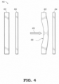
FIG. 4 is a diagram of aninductive sensor 400 to detect the presence of thefinger 320 of the user when using thehandheld controller 200 ofFIG. 2 in accordance with some embodiments. Theinductive sensor 400 is located on a printed circuit board and includes ametal plane 402 parallel to, and physically separated from, a coil 404 a small distance, where thecoil 404 is an inductor with an inductance value. When anexternal force 406 is applied to themetal plane 402 by an object, such as when thefinger 320 presses on theinductive sensor 400, themetal plane 402 undergoes adeflection 408 in relation to thecoil 404. Due to the proximity of themetal plane 402 to thecoil 404, thedeflection 408 causes a change in the inductance of thecoil 404. Based on Lenz's Law, the closer themetal plane 402 is to thecoil 404, the lesser the inductance of thecoil 404. The change in inductance value is detected by theprocessor 116 in the form of changes to the current and voltage through thecoil 404. In this manner, the presence and force applied by thefinger 320 can be detected by theprocessor 116 or a processor located in thehandheld controller 200. Theinductive sensor 400 thus is used to measure the variable force or pressure applied by thefinger 320. The force/pressure sensor 110 employs an inductive sensor as described herein. - In some embodiments, the
inductive sensor 400 also incorporates hysteresis functions as well as haptic feedback to thefinger 320 of the user. Hysteresis, as applied to the present disclosure, introduces a lag or delay in response to a button or sensor being activated. Hysteresis prevents the unintentional rapid cycling or bouncing of a sensor in response to input such as thefinger 320. Hysteresis aids the user's experience in the VR/AR environment by smoothing out the response of thesensors 110. Also, haptic feedback can recreate the sense of touch by applying forces, vibrations, or motion back to the user. This mechanical stimulation is used to aid in the creation and realism of virtual objects in a VR/AR environment. -
FIG. 5 is a flow diagram of amethod 500 for calculating the position of thefinger 320 ofFIG. 3 of the user based onmultiple sensors 110 as employed by the VR/AR system 100 ofFIG. 1 in accordance with some embodiments. In the present embodiment, themethod 500 usescapacitive sensors 300, but other embodiments employing other types of sensors are possible. Themethod 500 is but one embodiment of an algorithm for calculating the position of thefinger 320 in relation to thehandheld controller 200 ofFIG. 2 , and other embodiments are possible. In the present embodiment, thehandheld controller 200 is used with thetouch pad 204 having thirteensensors 110 arranged in a concentric hexagonal pattern, and forming two distinct regions. Themethod 500 begins atblock 502 where the VR/AR system 100 obtains measurements from the thirteen sensors via a wired or wireless communications path from thehandheld controller 200. Next, atblock 504, themethod 500 determines the median, or 7th largest, sensor measurement value based on the thirteen measurements. Atblock 506, the VR/AR system 100 subtracts the median sensor measurement value from each of the set of thirteen measurements. Next, atblock 508, the 6 largest measurement values are used to perform a centroiding procedure to obtain the X- and Y- positions of thefinger 320. The centroiding procedure includes calculating the geometric center of all of the measurements, and is represented by calculating the arithmetic mean of the 6 measurements. Atblock 510, the results of the centroiding procedure are passed through a filtering process via a Kalman filter to improve the resolution of the data and to minimize errors. Next, atblock 512, the results from the centroiding and filtering procedures are presented as X_Position and Y_Position values. The X_Position and Y_Position values represent to location of the finger in relation to the thirteensensors 110. Additionally, in some embodiments, movement data of thefinger 320 over time can be calculated by theprocessor 116 by calculating the X_Velocity and Y_Velocity values for thefinger 320 based on calculating and recording finger positions over time. -
FIG. 6 is a flow diagram of amethod 600 for employing a plurality ofsensors 110 located on thehandheld controller 200 ofFIG. 2 to sense the presence of one or more fingers of the user in the VR/AR system 100 ofFIG. 1 in accordance with some embodiments. Themethod 600 includes a user's hand and finger movement using thehandheld controller 200 atblock 602, where thehandheld controller 200 employssensors 110 arranged on thetouch pad 204 in a geometric pattern as disclosed herein. Next, atdecision block 604, theprocessor 116 determines whether any of the hover, touch, or force sensors detects any movement of thefingers 320. If one or more of thesensors 110 detects movement, themethod 600 continues with collecting sensor measurement data atblock 606. If, however, nofinger 320 movement is detected by thesensors 110, theprocessor 116 begins the baseline tracking procedure atblock 612 and the sensor recalibration function atblock 614.
Afterwards, themethod 600 returns to thedecision block 604 to await the detection of finger movement by thesensors 110. - Assuming the finger movement is detected at
decision block 604, themethod 600 continues with the sensor data from the hover, touch, and forcesensors 110 combined to form aggregate sensor data atblock 606. This data is sent to theprocessor 116. Atblock 608, themethod 600 continues with theprocessor 116 applying an algorithm to the aggregate sensor data. The algorithm can be themethod 500 ofFIG. 5 or another process for analyzing the sensor measurement data. Next, atblock 610, themethod 600 continues with theprocessor 116 calculating the estimated position of thefinger 320 of the user using the X_Position and Y_Position variables that are derived from the aggregate sensor data. Additionally, themethod 600 can also calculate the motion of thefinger 320 by using current and historical data from previous measurements to determine the X_Velocity and Y_Velocity of thefingers 320 over time as described herein. - In some embodiments, a method includes employing a plurality of sensors associated with a handheld controller, wherein each of the plurality of sensors comprises one of a hover, touch, and force/pressure sensor; generating, by one or more of the plurality of sensors, sensor data associated with positions of a user's hand and one or more fingers in relation to the handheld controller; combining the sensor data from the plurality of sensors to form aggregate sensor data; sending the aggregate sensor data to a processor; and generating estimated positions of the user's hand and one or more fingers based on the aggregate sensor data. In one aspect, at least one of sensors is a hover or touch sensor using capacitive sensing to sense the position of the user's hand or one or more fingers. In another aspect, at least one of the sensors is a force/pressure sensor using inductive sensing to sense when the user's hand or one or more fingers are in contact with the force/pressure sensor.
- In another aspect, processor performs a baseline tracking procedure to establish baseline current and voltage values for each of the plurality of sensors. In still another aspect the processor executes an algorithm to combine the output of one or more of the sensors which are force/pressure sensors with one of the sensors which is a hover or touch sensor to detect the presence of the user's fingers. In yet another aspect the sensors comprise a force/pressure sensor positioned on a trigger of the handheld controller, wherein the force/pressure sensor provides a continuous stream of sensor data indicative of a force the user's hand and fingers applies to the trigger. In still another aspect at least one of the plurality of sensors employs haptic feedback to the user's hand and/or one or more of the user's fingers. In another aspect, a touch pad associated with the handheld controller is partitioned into two or more regions, wherein each region comprises at least one of the plurality of sensors. In yet another aspect, the regions are hexagonal in shape.
- In some embodiments, a method includes: employing a plurality of sensors associated with a handheld controller, wherein each of the plurality of sensors comprises one of a hover, touch, and force/pressure sensor, and positioning the plurality of sensors in a pattern on a touch pad located on the handheld controller; sensing, by at least three of the plurality of sensors, contact by and/or proximity of a finger of a user, and generating, by the at least three of the plurality of sensors, sensor data associated with the position of the user's finger in relation to the handheld controller; combining the sensor data from the plurality of sensors to form aggregate sensor data; sending the aggregate sensor data to a processor; and calculating, by the processor executing an algorithm, a position of the finger in three dimensions, wherein the position of the finger is determined by triangulation using the sensor data from the at least three of the plurality of sensors in the aggregate sensor data. In one aspect, each of the at least three of the plurality of sensors uses one of capacitive sensing and inductive sensing.
- In another aspect, the algorithm includes: obtaining a set of measurements from N number of sensors of the at least three of the plurality of sensors; subtracting the median measurement value from each measurement; identifying a set of (N-1)/2 measurement values; calculating the arithmetic mean values of the set of (N-1)/2 measurement values; and forming X_Position and Y_Position values from the arithmetic mean values. In still another aspect, the method includes employing a force/pressure sensor positioned on a trigger of the handheld controller, wherein the force/pressure sensor provides a continuous stream of sensor data indicative of a force the user's hand and fingers applies to the trigger.
- In some embodiments, an apparatus includes: a handheld controller; a touch pad located on the handheld controller; a plurality of sensors positioned on the touch pad, wherein each sensor is a hover, touch, or force/pressure sensor, each sensor being arranged to sense when a user's hand or finger is proximal to or in contact with the sensor; the apparatus forming aggregate sensor data comprised of sensor data from multiple ones of the sensors simultaneously; and a processor, wherein the processor executes an algorithm using the aggregate sensor data. In one aspect, each of the plurality of sensors uses one of capacitive sensing and inductive sensing. In another aspect, the apparatus includes a grip of the handheld controller employing at least one force/pressure sensor. In still another aspect, at least one of the plurality of sensors employs haptic feedback to the user's hand and/or one or more fingers. In yet another aspect, the touch pad enables at least three of the sensors to be in contact with or proximal to one or more of the user's fingers, and the at least three sensors are used to triangulate a position of at least one such finger.
- In one aspect, the plurality of sensors positioned on the touch pad is comprised of a plurality of capacitive sensors arranged in a double hexagonal pattern, and the double hexagonal pattern is comprised of an outer hexagon and an inner hexagon in a concentric arrangement, and one of the plurality of sensors is located at the center of the double hexagonal pattern. In another aspect, the aggregate sensor data is formed by combining capacitance sensing measurements from at least one sensor associated with the outer hexagon and one sensor associated with the inner hexagon.
- In some embodiments, certain aspects of the techniques described above may implemented by one or more processors of a processing system executing software. The software comprises one or more sets of executable instructions stored or otherwise tangibly embodied on a non-transitory computer readable storage medium. The software can include the instructions and certain data that, when executed by the one or more processors, manipulate the one or more processors to perform one or more aspects of the techniques described above. The non-transitory computer readable storage medium can include, for example, a magnetic or optical disk storage device, solid state storage devices such as Flash memory, a cache, random access memory (RAM) or other non-volatile memory device or devices, and the like. The executable instructions stored on the non-transitory computer readable storage medium may be in source code, assembly language code, object code, or other instruction format that is interpreted or otherwise executable by one or more processors.
- A computer readable storage medium may include any storage medium, or combination of storage media, accessible by a computer system during use to provide instructions and/or data to the computer system. Such storage media can include, but is not limited to, optical media (e.g., compact disc (CD), digital versatile disc (DVD), Blu-Ray disc), magnetic media (e.g., floppy disc, magnetic tape, or magnetic hard drive), volatile memory (e.g., random access memory (RAM) or cache), non-volatile memory (e.g., read-only memory (ROM) or Flash memory), or microelectromechanical systems (MEMS)-based storage media. The computer readable storage medium may be embedded in the computing system (e.g., system RAM or ROM), fixedly attached to the computing system (e.g., a magnetic hard drive), removably attached to the computing system (e.g., an optical disc or Universal Serial Bus (USB)-based Flash memory), or coupled to the computer system via a wired or wireless network (e.g., network accessible storage (NAS)).
- Note that not all of the activities or elements described above in the general description are required, that a portion of a specific activity or device may not be required, and that one or more further activities may be performed, or elements included, in addition to those described. Still further, the order in which activities are listed are not necessarily the order in which they are performed. Also, the concepts have been described with reference to specific embodiments. However, one of ordinary skill in the art appreciates that various modifications and changes can be made without departing from the scope of the present disclosure as set forth in the claims below. Accordingly, the specification and figures are to be regarded in an illustrative rather than a restrictive sense, and all such modifications are intended to be included within the scope of the present disclosure.
- Benefits, other advantages, and solutions to problems have been described above with regard to specific embodiments. However, the benefits, advantages, solutions to problems, and any feature(s) that may cause any benefit, advantage, or solution to occur or become more pronounced are not to be construed as a critical, required, or essential feature of any or all the claims. Moreover, the particular embodiments disclosed above are illustrative only, as the disclosed subject matter may be modified and practiced in different but equivalent manners apparent to those skilled in the art having the benefit of the teachings herein. No limitations are intended to the details of construction or design herein shown, other than as described in the claims below. It is therefore evident that the particular embodiments disclosed above may be altered or modified and all such variations are considered within the scope of the disclosed subject matter. Accordingly, the protection sought herein is as set forth in the claims below.
- In the following, several exemplary embodiments are described:
- Example 1: A method comprising: employing a plurality of sensors associated with a handheld controller, wherein each of the plurality of sensors comprises one of a hover, touch, and force/pressure sensor; generating, by one or more of the plurality of sensors, sensor data associated with positions of a user's hand and one or more fingers in relation to the handheld controller; combining the sensor data from the plurality of sensors to form aggregate sensor data; sending the aggregate sensor data to a processor; and generating estimated positions of the user's hand and one or more fingers based on the aggregate sensor data.
- Example 2: The method of example 1, wherein at least one of sensors is a hover or touch sensor using capacitive sensing to sense the position of the user's hand or one or more fingers.
- Example 3: The method of example 1 or 2, wherein at least one of the sensors is a force/pressure sensor using inductive sensing to sense when the user's hand or one or more fingers are in contact with the force/pressure sensor.
- Example 4: The method of any preceding example, wherein the processor performs a baseline tracking procedure to establish baseline current and voltage values for each of the plurality of sensors.
- Example 5: The method of any preceding example, wherein the processor executes an algorithm to combine the output of one or more of the sensors which are force/pressure sensors with one of the sensors which is a hover or touch sensor to detect the presence of the user's fingers.
- Example 6: The method of any preceding example, wherein the sensors comprise a force/pressure sensor positioned on a trigger of the handheld controller, wherein the force/pressure sensor provides a continuous stream of sensor data indicative of a force the user's hand and fingers applies to the trigger.
- Example 7: The method of any preceding example, wherein at least one of the plurality of sensors employs haptic feedback to the user's hand and/or one or more of the user's fingers.
- Example 8: The method of any preceding example, wherein a touch pad associated with the handheld controller is partitioned into two or more regions, wherein each region comprises at least one of the plurality of sensors.
- Example 9: The method of example 8, wherein the regions are hexagonal in shape.
- Example 10: A method comprising: employing a plurality of sensors associated with a handheld controller, wherein each of the plurality of sensors comprises one of a hover, touch, and force/pressure sensor, and positioning the plurality of sensors in a pattern on a touch pad located on the handheld controller; sensing, by at least three of the plurality of sensors, contact by and/or proximity of a finger of a user, and generating, by the at least three of the plurality of sensors, sensor data associated with the position of the user's finger in relation to the handheld controller; combining the sensor data from the plurality of sensors to form aggregate sensor data; sending the aggregate sensor data to a processor; and calculating, by the processor executing an algorithm, a position of the finger in three dimensions, wherein the position of the finger is determined by triangulation using the sensor data from the at least three of the plurality of sensors in the aggregate sensor data.
- Example 11: The method of example 10, wherein each of the at least three of the plurality of sensors uses one of capacitive sensing and inductive sensing.
- Example 12: The method of example 10 or 11, wherein the algorithm comprises: obtaining a set of measurements from N number of sensors of the at least three of the plurality of sensors; subtracting the median measurement value from each measurement; identifying a set of (N-1)/2 measurement values; calculating the arithmetic mean values of the set of (N-1)/2 measurement values; and forming X_Position and Y_Position values from the arithmetic mean values.
- Example 13: The method of any of examples 10 to 12, further comprising employing a force/pressure sensor positioned on a trigger of the handheld controller, wherein the force/pressure sensor provides a continuous stream of sensor data indicative of a force the user's hand and fingers applies to the trigger.
- Example 14: An apparatus comprising: a handheld controller; a touch pad located on the handheld controller; a plurality of sensors positioned on the touch pad, wherein each sensor is a hover, touch, or force/pressure sensor, each sensor being arranged to sense when a user's hand or finger is proximal to or in contact with the sensor; the apparatus forming aggregate sensor data comprised of sensor data from multiple ones of the sensors simultaneously; and a processor, wherein the processor executes an algorithm using the aggregate sensor data.
- Example 15: The apparatus of example 14, wherein each of the plurality of sensors uses one of capacitive sensing and inductive sensing.
- Example 16: The apparatus of example 14 or 15, further comprising a grip of the handheld controller employing at least one force/pressure sensor.
- Example 17: The apparatus of any of examples 14 to 16, wherein at least one of the plurality of sensors employs haptic feedback to the user's hand and/or one or more fingers.
- Example 18: The apparatus of any of examples 14 to 17, wherein the touch pad enables at least three of the sensors to be in contact with or proximal to one or more of the user's fingers, and wherein the at least three sensors are used to triangulate a position of at least one such finger.
- Example 19: The apparatus of any of examples 14 to 18, wherein the plurality of sensors positioned on the touch pad is comprised of a plurality of capacitive sensors arranged in a double hexagonal pattern, and wherein the double hexagonal pattern is comprised of an outer hexagon and an inner hexagon in a concentric arrangement, and wherein one of the plurality of sensors is located at the center of the double hexagonal pattern.
- Example 20: The apparatus of example 19, wherein the aggregate sensor data is formed by combining capacitance sensing measurements from at least one sensor associated with the outer hexagon and one sensor associated with the inner hexagon.
Claims (15)
- A method comprising:employing a plurality of sensors on a handheld controller,wherein each of the plurality of sensors comprises one of a hover, touch, and force/pressure sensor, andwherein the plurality of sensors including at least one hover sensor, and at least one of a touch sensor and a force/pressure sensor;generating concurrently, by the plurality of sensors, sensor data associated with the position of a user's hand and finger in relation to the handheld controller;combining the sensor data from the plurality of sensors to form aggregate sensor data;sending the aggregate sensor data to a processor; andgenerating an estimated position of the user's hand and fingers in 3 dimensions based on the aggregate sensor data.
- The method of claim 1, wherein at least one hover and touch sensor uses capacitive sensing to sense the position of the user's hand and fingers and wherein the force/pressure sensor uses inductive sensing to sense when the user's hand and fingers are in contact with the force/pressure sensor.
- The method of any preceding claim, wherein the plurality of sensors includes a capacitive sensor, and wherein the processor performs a baseline tracking procedure to establish baseline current and voltage values for the capacitive sensor by:monitoring the capacitive sensor for a change in one or more of a current and a change in voltage;compensating for a shift in a baseline capacitance by detecting a change to a baseline value for the current or change to a baseline value for the voltage;performing a recalibration to reset the baseline current and the baseline voltage values of the capacitive sensor when the processor does not detect the presence of the user's finger; anddisabling the recalibration when the user's finger is near the capacitive sensor.
- The method of any preceding claim, wherein the processor combines the output of force/pressure sensors with output from one of the hover and touch sensors to detect the presence of the user's fingers.
- The method of any preceding claim, wherein the sensors comprise a force/pressure sensor positioned on a trigger of the handheld controller, wherein the force/pressure sensor provides a continuous stream of sensor data indicative of a force the user's hand and fingers applies to the trigger and/or wherein at least one of the plurality of sensors employs haptic feedback to the user's hand and fingers.
- The method of any preceding claim, wherein the touch pad is partitioned into two or more regions, wherein each region comprises at least one of the plurality of sensors, wherein, optionally, the regions are hexagonal in shape.
- A method comprising:employing a plurality of sensors on a handheld controller,wherein each of the plurality of sensors comprises one of a hover, touch, and force/pressure sensor, andwherein the plurality of sensors including at least one hover sensor, and at least one of a touch sensor and a force/pressure sensor;positioning the plurality of sensors in a pattern on a touch pad located on the handheld controller;generating concurrently, by the plurality of sensors, sensor data associated with the position of a user's hand and finger in relation to the handheld controller;combining the sensor data from the plurality of sensors to form aggregate sensor data;sensing, by at least three of the plurality of sensors, contact by at least one of the user's fingers;sending the aggregate sensor data to a processor; andcalculating, by the processor, a position of the finger in 3 dimensions, wherein the position of the finger is determined by triangulation using the aggregate sensor data.
- The method of claim 7, wherein each of the plurality of sensors uses one of capacitive sensing and inductive sensing.
- The method of claim 7 or 8, wherein the algorithm comprises:obtaining a set of measurements from N number of sensors of the plurality of sensors;subtracting the median measurement value from each measurement;identifying a set of (N-1)/2 measurement values;calculating the arithmetic mean values of the set of (N-1)/2 measurement values; andforming X_Position and Y_Position values from the arithmetic mean values
- The method of any of claims 7 to 9, further comprising employing a force/pressure sensor positioned on a trigger of the handheld controller, wherein the force/pressure sensor provides a continuous stream of sensor data indicative of a force the user's hand and fingers applies to the trigger.
- An apparatus comprising:a handheld controller;a touch pad located on the handheld controller;a plurality of hover, touch, and force/pressure sensors positioned on the touch pad, wherein the sensors sense when a user's hand and fingers is in contact with the sensors;aggregate sensor data formed by the plurality of sensors, wherein the aggregate sensor data are comprised of sensor data generated concurrently from the plurality of sensors; anda processor, using the aggregate sensor data, configured to:
generate an estimated position of the user's hand and fingers in 3 dimensions based on the aggregate sensor data. - The apparatus of claim 11, wherein each of the plurality of sensors uses one of capacitive sensing and inductive sensing; and/or further comprising a grip of the handheld controller employing at least one force/pressure sensor.
- The apparatus of any of claims 11 or 12, wherein at least one of the plurality of sensors employs haptic feedback to the user's hand and fingers.
- The apparatus of any of claims 11 to 13, wherein the touch pad enables at least three sensors to be in contact with the user's fingers, and wherein the at least three sensors are used to triangulate a position of at least one finger of the user's fingers.
- The apparatus of any of claims 11 to 14,wherein the plurality of sensors positioned on the touch pad is comprised of one or more capacitive sensors arranged in a double hexagonal pattern, andwherein the double hexagonal pattern is comprised of an outer hexagon and an inner hexagon in a concentric arrangement, andwherein one of the plurality of sensors is located at a center of the double hexagonal pattern,wherein, optionally, the aggregate sensor data are formed by combining capacitance sensing measurements from at least one sensors associated with the outer hexagon and one sensor associated with the inner hexagon.
Applications Claiming Priority (4)
| Application Number | Priority Date | Filing Date | Title |
|---|---|---|---|
| US201762588706P | 2017-11-20 | 2017-11-20 | |
| US16/111,702 US10599259B2 (en) | 2017-11-20 | 2018-08-24 | Virtual reality / augmented reality handheld controller sensing |
| EP18796326.9A EP3602256B1 (en) | 2017-11-20 | 2018-10-15 | Virtual reality / augmented reality handheld controller sensing |
| PCT/US2018/055808 WO2019099132A1 (en) | 2017-11-20 | 2018-10-15 | Virtual reality / augmented reality handheld controller sensing |
Related Parent Applications (2)
| Application Number | Title | Priority Date | Filing Date |
|---|---|---|---|
| EP18796326.9A Division EP3602256B1 (en) | 2017-11-20 | 2018-10-15 | Virtual reality / augmented reality handheld controller sensing |
| EP18796326.9A Division-Into EP3602256B1 (en) | 2017-11-20 | 2018-10-15 | Virtual reality / augmented reality handheld controller sensing |
Publications (1)
| Publication Number | Publication Date |
|---|---|
| EP4180924A1 true EP4180924A1 (en) | 2023-05-17 |
Family
ID=66533939
Family Applications (2)
| Application Number | Title | Priority Date | Filing Date |
|---|---|---|---|
| EP23150973.8A Pending EP4180924A1 (en) | 2017-11-20 | 2018-10-15 | Virtual reality / augmented reality handheld controller sensing |
| EP18796326.9A Active EP3602256B1 (en) | 2017-11-20 | 2018-10-15 | Virtual reality / augmented reality handheld controller sensing |
Family Applications After (1)
| Application Number | Title | Priority Date | Filing Date |
|---|---|---|---|
| EP18796326.9A Active EP3602256B1 (en) | 2017-11-20 | 2018-10-15 | Virtual reality / augmented reality handheld controller sensing |
Country Status (5)
| Country | Link |
|---|---|
| US (1) | US10599259B2 (en) |
| EP (2) | EP4180924A1 (en) |
| KR (1) | KR102281883B1 (en) |
| CN (1) | CN110651238A (en) |
| WO (1) | WO2019099132A1 (en) |
Families Citing this family (32)
| Publication number | Priority date | Publication date | Assignee | Title |
|---|---|---|---|---|
| EP3062142B1 (en) | 2015-02-26 | 2018-10-03 | Nokia Technologies OY | Apparatus for a near-eye display |
| US10650552B2 (en) | 2016-12-29 | 2020-05-12 | Magic Leap, Inc. | Systems and methods for augmented reality |
| EP3343267B1 (en) | 2016-12-30 | 2024-01-24 | Magic Leap, Inc. | Polychromatic light out-coupling apparatus, near-eye displays comprising the same, and method of out-coupling polychromatic light |
| US10578870B2 (en) | 2017-07-26 | 2020-03-03 | Magic Leap, Inc. | Exit pupil expander |
| JP7282090B2 (en) | 2017-12-10 | 2023-05-26 | マジック リープ, インコーポレイテッド | Antireflection coating on optical waveguide |
| CN111712751B (en) | 2017-12-20 | 2022-11-01 | 奇跃公司 | Insert for augmented reality viewing apparatus |
| EP4415355A3 (en) | 2018-03-15 | 2024-09-04 | Magic Leap, Inc. | Image correction due to deformation of components of a viewing device |
| CN112601975B (en) | 2018-05-31 | 2024-09-06 | 奇跃公司 | Radar head posture positioning |
| WO2020010097A1 (en) | 2018-07-02 | 2020-01-09 | Magic Leap, Inc. | Pixel intensity modulation using modifying gain values |
| US11856479B2 (en) | 2018-07-03 | 2023-12-26 | Magic Leap, Inc. | Systems and methods for virtual and augmented reality along a route with markers |
| US11510027B2 (en) | 2018-07-03 | 2022-11-22 | Magic Leap, Inc. | Systems and methods for virtual and augmented reality |
| JP7374981B2 (en) | 2018-07-10 | 2023-11-07 | マジック リープ, インコーポレイテッド | Thread weaving for cross instruction set architecture procedure calls |
| US11598651B2 (en) | 2018-07-24 | 2023-03-07 | Magic Leap, Inc. | Temperature dependent calibration of movement detection devices |
| WO2020023543A1 (en) | 2018-07-24 | 2020-01-30 | Magic Leap, Inc. | Viewing device with dust seal integration |
| EP4650919A3 (en) | 2018-08-02 | 2026-01-21 | Magic Leap, Inc. | A viewing system with interpupillary distance compensation based on head motion |
| EP3830631A4 (en) | 2018-08-03 | 2021-10-27 | Magic Leap, Inc. | NON-FUSED POSE DRIFT CORRECTION OF A FUSED TOTEM IN A USER INTERACTION SYSTEM |
| JP7487176B2 (en) | 2018-08-22 | 2024-05-20 | マジック リープ, インコーポレイテッド | Patient Visibility System |
| JP7543274B2 (en) | 2018-12-21 | 2024-09-02 | マジック リープ, インコーポレイテッド | Air pocket structures for enhancing total internal reflection in waveguides. |
| EP3939030B1 (en) | 2019-03-12 | 2025-10-29 | Magic Leap, Inc. | Registration of local content between first and second augmented reality viewers |
| CN120812326A (en) | 2019-05-01 | 2025-10-17 | 奇跃公司 | Content providing system and method |
| US10948980B2 (en) * | 2019-05-10 | 2021-03-16 | Apple Inc. | Electronic device system with controllers |
| US11042247B2 (en) * | 2019-06-14 | 2021-06-22 | Valve Corporation | Cluster-based sensor assignment |
| WO2021021670A1 (en) | 2019-07-26 | 2021-02-04 | Magic Leap, Inc. | Systems and methods for augmented reality |
| US12033081B2 (en) | 2019-11-14 | 2024-07-09 | Magic Leap, Inc. | Systems and methods for virtual and augmented reality |
| EP4058979A4 (en) | 2019-11-15 | 2023-01-11 | Magic Leap, Inc. | A viewing system for use in a surgical environment |
| US12402955B2 (en) * | 2020-06-29 | 2025-09-02 | Regents Of The University Of Minnesota | Extended-reality visualization of endovascular navigation |
| USD991266S1 (en) * | 2020-12-18 | 2023-07-04 | Google Llc | Display screen or portion thereof with graphical user interface |
| USD991267S1 (en) | 2020-12-18 | 2023-07-04 | Google Llc | Display screen or portion thereof with graphical user interface |
| USD983815S1 (en) * | 2020-12-22 | 2023-04-18 | Google Llc | Display screen or portion thereof with animated graphical user interface |
| USD983816S1 (en) | 2020-12-22 | 2023-04-18 | Google Llc | Display screen or portion thereof with animated graphical user interface |
| KR102526843B1 (en) | 2021-04-22 | 2023-04-27 | 한국기술교육대학교 산학협력단 | AR medium based on augmented reality |
| CN117883648A (en) * | 2024-03-01 | 2024-04-16 | 深圳市路特佳成供应链管理有限公司 | Control device, method, apparatus, electronic device and storage medium |
Citations (5)
| Publication number | Priority date | Publication date | Assignee | Title |
|---|---|---|---|---|
| US20020015024A1 (en) * | 1998-01-26 | 2002-02-07 | University Of Delaware | Method and apparatus for integrating manual input |
| US20110118028A1 (en) * | 2009-11-16 | 2011-05-19 | Broadcom Corporation | Hand-held gaming device with configurable touch sensitive panel(s) |
| US20160162031A1 (en) * | 2012-05-09 | 2016-06-09 | Apple Inc. | Thresholds for Determining Feedback in Computing Devices |
| WO2016140924A1 (en) * | 2015-03-01 | 2016-09-09 | Tactical Haptics | Embedded grasp sensing devices, systems, and methods |
| US20160361638A1 (en) * | 2015-06-11 | 2016-12-15 | Oculus Vr, Llc | Hand-Held Controllers with Capacitive Touch Sensors for Virtual-Reality Systems |
Family Cites Families (10)
| Publication number | Priority date | Publication date | Assignee | Title |
|---|---|---|---|---|
| GB9422911D0 (en) | 1994-11-14 | 1995-01-04 | Moonstone Technology Ltd | Capacitive touch detectors |
| US20070057922A1 (en) | 2005-09-13 | 2007-03-15 | International Business Machines Corporation | Input having concentric touch pads |
| US8203502B1 (en) * | 2011-05-25 | 2012-06-19 | Google Inc. | Wearable heads-up display with integrated finger-tracking input sensor |
| US8878823B1 (en) | 2011-07-27 | 2014-11-04 | Cypress Semiconductor Corporation | Dynamic shield electrode of a stylus |
| JP5781886B2 (en) * | 2011-10-05 | 2015-09-24 | 富士フイルム株式会社 | Conductive sheet, touch panel and display device |
| US9319149B2 (en) * | 2013-03-13 | 2016-04-19 | Aliphcom | Proximity-based control of media devices for media presentations |
| JP6396478B2 (en) | 2013-09-27 | 2018-09-26 | センセル インコーポレイテッドSensel,Inc. | Touch sensor detection system and method |
| EP3035173B1 (en) * | 2014-12-15 | 2018-02-07 | Nxp B.V. | User interface unit, electronic device and manufactoring method |
| US10025439B2 (en) | 2015-04-02 | 2018-07-17 | Parade Technologies, Ltd. | Virtual sensor mirroring for circular touch panels |
| US9746937B2 (en) * | 2015-10-02 | 2017-08-29 | Blackberry Limited | Method and apparatus for movable assembly position sensing and virtual keyboard display |
-
2018
- 2018-08-24 US US16/111,702 patent/US10599259B2/en active Active
- 2018-10-15 KR KR1020197034594A patent/KR102281883B1/en active Active
- 2018-10-15 WO PCT/US2018/055808 patent/WO2019099132A1/en not_active Ceased
- 2018-10-15 EP EP23150973.8A patent/EP4180924A1/en active Pending
- 2018-10-15 CN CN201880033324.1A patent/CN110651238A/en active Pending
- 2018-10-15 EP EP18796326.9A patent/EP3602256B1/en active Active
Patent Citations (5)
| Publication number | Priority date | Publication date | Assignee | Title |
|---|---|---|---|---|
| US20020015024A1 (en) * | 1998-01-26 | 2002-02-07 | University Of Delaware | Method and apparatus for integrating manual input |
| US20110118028A1 (en) * | 2009-11-16 | 2011-05-19 | Broadcom Corporation | Hand-held gaming device with configurable touch sensitive panel(s) |
| US20160162031A1 (en) * | 2012-05-09 | 2016-06-09 | Apple Inc. | Thresholds for Determining Feedback in Computing Devices |
| WO2016140924A1 (en) * | 2015-03-01 | 2016-09-09 | Tactical Haptics | Embedded grasp sensing devices, systems, and methods |
| US20160361638A1 (en) * | 2015-06-11 | 2016-12-15 | Oculus Vr, Llc | Hand-Held Controllers with Capacitive Touch Sensors for Virtual-Reality Systems |
Also Published As
| Publication number | Publication date |
|---|---|
| WO2019099132A1 (en) | 2019-05-23 |
| US10599259B2 (en) | 2020-03-24 |
| EP3602256A1 (en) | 2020-02-05 |
| KR20200003841A (en) | 2020-01-10 |
| US20190155439A1 (en) | 2019-05-23 |
| KR102281883B1 (en) | 2021-07-28 |
| CN110651238A (en) | 2020-01-03 |
| EP3602256B1 (en) | 2023-02-15 |
Similar Documents
| Publication | Publication Date | Title |
|---|---|---|
| US10599259B2 (en) | Virtual reality / augmented reality handheld controller sensing | |
| US11016569B2 (en) | Wearable device and method for providing feedback of wearable device | |
| US8830189B2 (en) | Device and method for monitoring the object's behavior | |
| US9575562B2 (en) | User interface systems and methods for managing multiple regions | |
| US11209916B1 (en) | Dominant hand usage for an augmented/virtual reality device | |
| JP2018504682A5 (en) | ||
| WO2012032515A1 (en) | Device and method for controlling the behavior of virtual objects on a display | |
| KR102347248B1 (en) | Method and apparatus for recognizing touch gesture | |
| JP2019537084A (en) | Touch-sensitive keyboard | |
| WO2013055571A1 (en) | Information input apparatus and method for controlling information input apparatus | |
| US9405383B2 (en) | Device and method for disambiguating region presses on a capacitive sensing device | |
| US20150261330A1 (en) | Method of using finger surface area change on touch-screen devices - simulating pressure | |
| US9870080B2 (en) | Method, system, and device for controlling a cursor or user interface action as a function of touch and force input | |
| CN103842945A (en) | Object designation method, device and computer program | |
| CN205318322U (en) | Virtual reality sense of touch feedback device | |
| CN115053206A (en) | System for recording a trajectory traced by an implement on a writing surface | |
| KR101588021B1 (en) | An input device using head movement | |
| US11360632B2 (en) | Information processing system | |
| KR101996232B1 (en) | Apparatus and method for user input | |
| US20140160017A1 (en) | Electronic apparatus controll method for performing predetermined action based on object displacement and related apparatus thereof | |
| EP3374847B1 (en) | Controlling operation of a 3d tracking device | |
| Heukers | A Smartphone-based Controller for Virtual Reality Applications | |
| KR20160056609A (en) | 3d hovering digitizer |
Legal Events
| Date | Code | Title | Description |
|---|---|---|---|
| PUAI | Public reference made under article 153(3) epc to a published international application that has entered the european phase |
Free format text: ORIGINAL CODE: 0009012 |
|
| STAA | Information on the status of an ep patent application or granted ep patent |
Free format text: STATUS: THE APPLICATION HAS BEEN PUBLISHED |
|
| AC | Divisional application: reference to earlier application |
Ref document number: 3602256 Country of ref document: EP Kind code of ref document: P |
|
| AK | Designated contracting states |
Kind code of ref document: A1 Designated state(s): AL AT BE BG CH CY CZ DE DK EE ES FI FR GB GR HR HU IE IS IT LI LT LU LV MC MK MT NL NO PL PT RO RS SE SI SK SM TR |
|
| STAA | Information on the status of an ep patent application or granted ep patent |
Free format text: STATUS: REQUEST FOR EXAMINATION WAS MADE |
|
| 17P | Request for examination filed |
Effective date: 20231113 |
|
| RBV | Designated contracting states (corrected) |
Designated state(s): AL AT BE BG CH CY CZ DE DK EE ES FI FR GB GR HR HU IE IS IT LI LT LU LV MC MK MT NL NO PL PT RO RS SE SI SK SM TR |
|
| GRAP | Despatch of communication of intention to grant a patent |
Free format text: ORIGINAL CODE: EPIDOSNIGR1 |
|
| STAA | Information on the status of an ep patent application or granted ep patent |
Free format text: STATUS: GRANT OF PATENT IS INTENDED |
|
| INTG | Intention to grant announced |
Effective date: 20251013 |
|
| GRAJ | Information related to disapproval of communication of intention to grant by the applicant or resumption of examination proceedings by the epo deleted |
Free format text: ORIGINAL CODE: EPIDOSDIGR1 |
|
| STAA | Information on the status of an ep patent application or granted ep patent |
Free format text: STATUS: REQUEST FOR EXAMINATION WAS MADE |
|
| GRAP | Despatch of communication of intention to grant a patent |
Free format text: ORIGINAL CODE: EPIDOSNIGR1 |
|
| STAA | Information on the status of an ep patent application or granted ep patent |
Free format text: STATUS: GRANT OF PATENT IS INTENDED |
|
| INTC | Intention to grant announced (deleted) | ||
| INTG | Intention to grant announced |
Effective date: 20260220 |