EP4180912A1 - Casing assembly with an accomodation recess for a stylus - Google Patents
Casing assembly with an accomodation recess for a stylus Download PDFInfo
- Publication number
- EP4180912A1 EP4180912A1 EP22205771.3A EP22205771A EP4180912A1 EP 4180912 A1 EP4180912 A1 EP 4180912A1 EP 22205771 A EP22205771 A EP 22205771A EP 4180912 A1 EP4180912 A1 EP 4180912A1
- Authority
- EP
- European Patent Office
- Prior art keywords
- accommodation recess
- button
- stylus
- casing
- operation portion
- Prior art date
- Legal status (The legal status is an assumption and is not a legal conclusion. Google has not performed a legal analysis and makes no representation as to the accuracy of the status listed.)
- Pending
Links
Images




Classifications
-
- G—PHYSICS
- G06—COMPUTING OR CALCULATING; COUNTING
- G06F—ELECTRIC DIGITAL DATA PROCESSING
- G06F1/00—Details not covered by groups G06F3/00 - G06F13/00 and G06F21/00
- G06F1/16—Constructional details or arrangements
- G06F1/1613—Constructional details or arrangements for portable computers
- G06F1/1626—Constructional details or arrangements for portable computers with a single-body enclosure integrating a flat display, e.g. Personal Digital Assistants [PDAs]
-
- G—PHYSICS
- G06—COMPUTING OR CALCULATING; COUNTING
- G06F—ELECTRIC DIGITAL DATA PROCESSING
- G06F1/00—Details not covered by groups G06F3/00 - G06F13/00 and G06F21/00
- G06F1/16—Constructional details or arrangements
- G06F1/1601—Constructional details related to the housing of computer displays, e.g. of CRT monitors, of flat displays
- G06F1/1607—Arrangements to support accessories mechanically attached to the display housing
-
- G—PHYSICS
- G06—COMPUTING OR CALCULATING; COUNTING
- G06F—ELECTRIC DIGITAL DATA PROCESSING
- G06F1/00—Details not covered by groups G06F3/00 - G06F13/00 and G06F21/00
- G06F1/16—Constructional details or arrangements
-
- G—PHYSICS
- G06—COMPUTING OR CALCULATING; COUNTING
- G06F—ELECTRIC DIGITAL DATA PROCESSING
- G06F1/00—Details not covered by groups G06F3/00 - G06F13/00 and G06F21/00
- G06F1/16—Constructional details or arrangements
- G06F1/1613—Constructional details or arrangements for portable computers
- G06F1/1633—Constructional details or arrangements of portable computers not specific to the type of enclosures covered by groups G06F1/1615 - G06F1/1626
- G06F1/1637—Details related to the display arrangement, including those related to the mounting of the display in the housing
- G06F1/1643—Details related to the display arrangement, including those related to the mounting of the display in the housing the display being associated to a digitizer, e.g. laptops that can be used as penpads
-
- G—PHYSICS
- G06—COMPUTING OR CALCULATING; COUNTING
- G06F—ELECTRIC DIGITAL DATA PROCESSING
- G06F1/00—Details not covered by groups G06F3/00 - G06F13/00 and G06F21/00
- G06F1/16—Constructional details or arrangements
- G06F1/18—Packaging or power distribution
- G06F1/181—Enclosures
-
- G—PHYSICS
- G06—COMPUTING OR CALCULATING; COUNTING
- G06F—ELECTRIC DIGITAL DATA PROCESSING
- G06F3/00—Input arrangements for transferring data to be processed into a form capable of being handled by the computer; Output arrangements for transferring data from processing unit to output unit, e.g. interface arrangements
- G06F3/01—Input arrangements or combined input and output arrangements for interaction between user and computer
- G06F3/03—Arrangements for converting the position or the displacement of a member into a coded form
- G06F3/033—Pointing devices displaced or positioned by the user, e.g. mice, trackballs, pens or joysticks; Accessories therefor
- G06F3/0354—Pointing devices displaced or positioned by the user, e.g. mice, trackballs, pens or joysticks; Accessories therefor with detection of two-dimensional [2D] relative movements between the device, or an operating part thereof, and a plane or surface, e.g. 2D mice, trackballs, pens or pucks
- G06F3/03545—Pens or stylus
-
- G—PHYSICS
- G06—COMPUTING OR CALCULATING; COUNTING
- G06F—ELECTRIC DIGITAL DATA PROCESSING
- G06F2200/00—Indexing scheme relating to G06F1/04 - G06F1/32
- G06F2200/16—Indexing scheme relating to G06F1/16 - G06F1/18
- G06F2200/163—Indexing scheme relating to constructional details of the computer
- G06F2200/1632—Pen holder integrated in the computer
Definitions
- the present invention relates to a casing assembly and, more particularly, to a casing assembly for accommodating a stylus.
- tablet computers are commonly used by people in the daily lives or for work.
- a tablet computer may be used selectively with a stylus to perform operations such as writing, manipulating and drawing.
- a current common tablet computer is provided with an accommodation recess for placing a stylus.
- the stylus When the stylus is not in use, the stylus may be stored in the accommodation recess and be prevented from being lost.
- the stylus In order to prevent the stylus stored from unexpectedly disengaging from the accommodation recess, the stylus is secured in the accommodation recess by a fixing means, and a user needs to pick the stylus by a finger in order to get the stylus out of the accommodation recess.
- the stylus is secured too tightly in the accommodation recess, it may be difficult for the user to pick the stylus out of the accommodation recess. More particularly, when a user wears gloves, picking the stylus out of the accommodation recess by a finger may become even more difficult under the influence of the thickness of the gloves. Therefore, manufacturers of tablet computers are dedicated to improving such issue.
- the present invention provides a casing assembly that allows a stylus to be easily taken out of an accommodation recess.
- a casing assembly for accommodating a stylus is disclosed by an embodiment of the present invention.
- the casing assembly includes a casing and a button.
- the casing has an accommodation recess and an opening in communication with each other.
- the accommodation recess has a first end and a second end opposite to each other on a longitudinal axis thereof, and accommodates the stylus.
- the opening extends from the first end to the second end.
- the button includes an operation portion and a pushing portion connected to each other.
- the operation portion is pivotally disposed at the casing so as to be pivotable between an initial position and a released position.
- the pushing portion is located in the accommodation recess. When the operation portion is pivoted from the initial position to the released position, the pushing portion in the accommodation recess is moved toward the opening so as to push the stylus out of the accommodation recess.
- a casing assembly for accommodating a stylus is further disclosed by another embodiment of the present invention.
- the casing assembly includes a casing and a button.
- the casing has a groove.
- the button is movably disposed in the groove of the casing so as to be movable between an initial position and a released position.
- the button has a pushing portion, and an accommodation recess and an opening that are in communication with each other.
- the accommodation recess has a first end and a second end opposite to each other on a longitudinal axis thereof, and accommodates the stylus.
- the opening extends from the first end to the second end.
- the pushing portion of the button is enabled to push the stylus out of the accommodation recess by operating the operation portion of the button.
- the design of operating the button to withdraw the stylus from the accommodation recess provides a more convenient stylus pick-up operation.
- the user is still able to easily press the button to push the stylus out of the accommodation recess and then directly take the stylus.
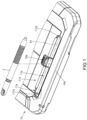
- FIG. 1 shows a three-dimensional schematic diagram of a casing assembly and a stylus disclosed according to a first embodiment of the present invention.
- FIG. 2 is an exploded schematic diagram of FIG. 1 .
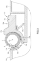
- FIG. 3 is a cross-sectional schematic diagram of FIG. 1 .
- a casing assembly 1a is for accommodating a stylus 2.
- the casing assembly 1a includes a casing 10a and a button 20a.
- the casing assembly 1a may further include a magnetic member 30a and two elastic members 40a.
- the casing assembly 1a is, for example, a casing of an electronic device.
- the casing 10a is, for example but not limited to, a backplate of a tablet computer.
- the casing 10a has an outer surface 11a, an accommodation recess 12a and an opening 13a.
- the accommodation recess 12a is formed as being recessed from the outer surface 11a, and has a first end 121a and a second end 122a opposite to each other.
- the first end 121a and the second end 122a are respectively located on two opposite sides on a longitudinal axis P1 of the accommodation recess 12a.
- a plane where the opening 13a is located is, for example, coplanar with the outer surface 11a of the casing 10a, and the opening 13a extends from the first end 121a to the second end 122a of the accommodation recess 12a.
- the accommodation recess 12a is for accommodating the stylus 2.
- the plane where the opening 13a is located is not limited to being coplanar with the outer surface 11a of the casing 10a.
- the plane where the opening is located may be non-coplanar with the outer surface of the casing, and may be, for example, higher than the outer surface of the casing.
- the magnetic member 30a is, for example, embedded in the casing 10a, and is near the accommodation recess 12a.
- the magnetic member 30a is for magnetically attracting another magnetic member 3 disposed in the stylus 2, and hence magnetically fixes the stylus 2 in the accommodation recess 12a.
- the magnetic member 30a is not limited to being embedded in the casing 10a.
- the magnetic member may be exposed from an inner wall surface of the accommodation recess.
- the magnetic member may be omitted from the casing assembly.
- the casing 10a may further include a button slot 14a.
- the button slot 14a is formed as being recessed from an inner wall surface 123a of the accommodation recess 12a, and is located between the first end 121a and the second end 122a of the accommodation recess 12a.
- the button 20a includes an operation portion 21a, a pushing portion 22a and a stopping portion 23a.
- the pushing portion 22a and the stopping portion 23a are connected to two opposite sides of the operation portion 21a, respectively, and the operation portion 21a, the pushing portion 22a and the stopping portion 23a jointly form a groove 24a.
- the groove 24a is for collaborating with the accommodation recess 12a to accommodate the stylus 2.
- the operation portion 21a is in part located in the button slot 14a and the operation portion 21a is pivotally disposed at the casing 10a, and the pushing portion 22a is located in the accommodation recess 12a.
- the operation portion 21a is adapted to be pivotable between an initial position A1 (as shown in FIG. 3 ) and a released position A2 (as shown in FIG. 4 ).
- the two elastic members 40a are, for example, torsion springs. On of the elastic members 40a is disposed between one side of the operation portion 21a of the button 20a and the casing 10a, and the other elastic member 40a is disposed between the other side of the operation portion 21a of the button 20a and the casing 10a.
- the two elastic members 40a are for applying a force for pivoting the operation portion 21a from the released position A2 to the initial position A1.
- the pushing portion 22a is located on one side of the accommodation recess 12a away from the opening 13a
- the stopping portion 23a is located at the opening 13a and extends to be diagonally above the accommodation recess 12a, so as to limit the stylus 2 within the accommodation recess 12a.
- FIG. 4 shows a cross-sectional schematic diagram of the stylus in FIG. 3 disengaged from the accommodation recess.
- the operation portion 21a of the button 20a may be pressed by a finger, so that the operation portion 21a is pivoted from the initial position A1 to the released position A2.
- the operation portion 21a causes the elastic members 40a to store an elastic restoring force, the stopping portion 23a is away from the opening 13a, and the pushing portion 22a moves from one side of the accommodation recess 12a away from the opening 13a toward the opening 13a.
- the thrust of the pushing portion 22a of the button 20a overcomes the magnetic attraction force between the two magnetic members 30a and 3, and then pushes the stylus 2 (located in the accommodation recess 12a) out of the accommodation recess 12a, allowing the stylus 2 to be taken directly.
- the elastic force of the elastic members 40a causes the operation portion 21a of the button 20a to return from the released position A2 to the initial position A1.
- the pushing portion 22a of the button 20a is enabled to push the stylus 2 out of the accommodation recess 12a by pressing the operation portion 21a of the button 20a.
- the design of operating the button 20a to withdraw the stylus 2 from the accommodation recess 12a provides a more convenient stylus pick-up operation.
- the user is still able to easily press the button 20a to push the stylus 2 out of the accommodation recess 12a and then directly take the stylus 2.
- the stylus 2 is pushed out of the accommodation recess 12a by the pushing portion 22a of the button 20a, in a direction substantially perpendicular to the longitudinal axis P1 of the accommodation recess 12a, but not in a direction of the longitudinal axis P1 of the accommodation recess 12a.
- the accommodation recess 12a of the casing 10a it is not necessary for the accommodation recess 12a of the casing 10a to extend to the edge of the casing 10a, hence minimizing the influence of a reduced internal space of the casing 10a caused by the accommodation recess 12a provided and further benefiting the utilization of the internal space of the casing 10a.
- the stylus 2 is first placed in the groove 24a, and the stylus 2 is brought back to the accommodation recess 12a by the button 20a, while the operation portion 21a of the button 20a is pivoted back to the initial position A1 by the elastic force of the elastic members 40a.
- the stylus 2 is directly fitted into the accommodation recess 12a and the groove 24a.
- the stylus 2 in the accommodation recess 12a is limited by the stopping portion 23a.
- the casing 10a receives an unexpected external impact (such as falling onto the ground), it is ensured that the stylus 2 does not disengage from the accommodation recess 12a.
- the number of the elastic members 40a is not limited to being two.
- the casing assembly may include only one elastic member.
- the elastic member may be omitted from the casing assembly. In such configuration, the button may be kept at the initial position by an appropriate structure or element when no external force is exerted thereon.
- FIG. 5 shows a three-dimensional schematic diagram of a casing assembly and a stylus disclosed according to a second embodiment of the present invention.
- FIG. 6 shows an exploded schematic diagram of FIG. 5 .
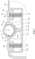
- FIG. 7 shows a cross-sectional schematic diagram of FIG. 5 .
- a casing assembly 1b is for accommodating a stylus 2.
- the casing assembly 1b includes a casing 10b and a button 20b.
- the casing assembly 1b may further include two elastic members 41b and 42b.
- the casing 10b is, for example, a backplate of a tablet computer.
- the casing 10b has a receiving slot 11b.
- the receiving slot 11b has, for example, a first receiving portion 111b and two second receiving portions 112b.
- the first receiving portion 111b is located between the two second receiving portions 112b, and is in communication with the two second receiving portions 112b.
- a length L1 of the first receiving portion 111b is greater than a length L2 of the two second receiving portions 112b.
- the button 20b is movably disposed in the receiving slot 11b of the casing 10b. More specifically, the button 20b has an accommodation recess 21b, an arc inner wall surface 22b, an opening 23b, a through hole 24b and a pushing portion 25b.
- the accommodation recess 21b is formed by the arc inner wall surface 22b, and has a first end 211b and a second end 212b opposite to each other on a longitudinal axis P2 of the accommodation recess 21b.
- the opening 23b and the through hole 24b are located on two opposite sides of the accommodation recess 21b and are both in communication with the accommodation recess 21b,and the opening 23b extends from the first end 211b to the second end 212b.
- the accommodation recess 21b is for accommodating the stylus 2.
- the first receiving portion 111b of the receiving slot 11b has a slot opening 1111b and a slot bottom surface 1112b, wherein the slot bottom surface 1112b faces the slot opening 1111b.
- the pushing portion 25b is, for example, a column, and the pushing portion 25b is connected to the slot bottom surface 1112b of the first receiving portion 111b and is insertedly disposed in the through hole 24b.
- the button 20b includes a receiving portion 26b, a first stopping portion 27b, a second stopping portion 28b, a first operation portion 29b and a second operation portion 30b.
- the first stopping portion 27b and the first operation portion 29b are connected to one side of the receiving portion 26b, and extend toward different directions, respectively.
- the second stopping portion 28b and the second operation portion 30b are connected to the other side of the receiving portion 26b, and extend toward different directions, respectively.
- Different portions of the arc inner wall surface 22b forming the accommodation recess 21b are located at the receiving portion 26b, the first stopping portion 27b and the second stopping portion 28b, respectively.
- the accommodation recess 21b is jointly formed by the receiving portion 26b, the first stopping portion 27b and the second stopping portion 28b.
- the receiving portion 26b is located at the first receiving portion 111b of the receiving slot 11b, and the first operation portion 29b and the second operation portion 30b are located at the two second receiving portions 112b of the receiving slot 11b, respectively.
- the button 20b is adapted to be movable between an initial position B1 (as shown in FIG. 7 ) and a released position B2 (as shown in FIG. 8 ) relative to the casing 10b.
- the two elastic members 41b and 42b are, for example, compression springs.
- the two elastic members 41b and 42b are located at the two second receiving portions 112b of the receiving slot 11b, respectively, two opposite ends of the elastic member 41b are connected to the first operation portion 29b of the button 20b and the casing 10b, respectively, and two opposite ends of the elastic member 42b are connected to the second operation portion 30b of the button 20b and the casing 10b, respectively.
- the two elastic members 41b and 42b are for applying a force for moving the button 20b from the released position B2 to the initial position B1.
- the stylus 2 is limited by the first stopping portion 27b and the second stopping portion 28b and is hence fixed in the accommodation recess 21b.
- the pushing portion 25b of the button 20b is, for example, slightly protruding from the arc inner wall surface 22b of the button 20b, and is located on one side of the accommodation recess 21b away from the opening 23b.
- FIG. 8 shows a cross-sectional schematic diagram of the stylus in FIG. 7 disengaged from the accommodation recess.
- the first operation portion 29b and the second operation portion 30b of the button 20b may be pressed by two fingers, such that the button 20b moves from the initial position B1 to the released position B2.
- the receiving portion 26b of the button 20b moves toward the slot bottom surface 1112b of the first receiving portion 111b of the casing 10b, such that the pushing portion 25b protrudes even more from the arc inner wall surface 22b and approaches the opening 23b of the button 20b along a radial direction of the arc inner wall surface 22b, and overcomes the limitation posed by the first stopping portion 27b and the second stopping portion 28b so further push the stylus 2 out of the accommodation recess 21b.
- the elastic force of the elastic members 41b and 42b causes the button 20b to return from the released position B2 to the initial position B1.
- the pushing portion 25b of the button 20b is enabled to push the stylus 2 out of the accommodation recess 21b by pressing the first operation portion 29b and the second operation portion 30b of the button 20b.
- the design of operating the button 20b to withdraw the stylus 2 from the accommodation recess 21b provides a more convenient stylus pick-up operation.
- the user is still able to easily press the button 20b to push the stylus 2 out of the accommodation recess 21b and then directly take the stylus 2.
- the stylus 2 is pushed out of the accommodation recess 21b by the pushing portion 25b of the button 20b, in a direction perpendicular to the longitudinal axis P2 of the accommodation recess 21b, but not in a direction of the longitudinal axis P2 of the accommodation recess 21b.
- the accommodation recess 21b it is not necessary for the accommodation recess 21b to extend to the edge of the casing 10b, hence minimizing the influence of a reduced internal space of the casing 10b caused by the accommodation recess 21b provided and further benefiting the utilization of the internal space of the casing 10b.
- the button 20b when the button 20b is not pressed, even if the casing 10b receives an unexpected external impact (such as falling onto the ground), it is ensured that the stylus 2 located in the accommodation recess 21b is still limited by the first stopping portion 27b and the second stopping portion 28b, and is kept in the accommodation recess 21b.
- the number of the elastic members 41b and 42b is two; however, the present invention is not limited thereto.
- the casing assembly may include only one elastic member.
- the elastic member may be omitted from the casing assembly.
- the pushing portion 25b is not limited to being slightly protruding from the arc inner wall surface 22b of the button 20b.
- one end of the pushing portion may be aligned with the arc inner surface of the button or be withdrawn into the arc inner surface of the button.
- the button 20b has a through hole 24b for the pushing portion 25b to pass through; however, the present invention is not limited thereto. In another embodiment, the button may exclude such through hole. In such configuration, the pushing portion may be located next to one of the two opposite ends of the receiving portion of the button. When the button moves from the initial position to the released position, the pushing portion is still able to push the stylus out of the accommodation recess.
- the surface forming the accommodation recess 21b is the arc inner wall surface 22b; however, the present invention is not limited thereto. In another embodiment, the surface forming the accommodation recess may be a surface with angles and corners.
- the button 20b includes two operation portions (the first operation portion 29b and the second operation portion 30b); however, the present invention is not limited thereto. In another embodiment, the button may include only one operation portion.
- the pushing portion of the button is enabled to push the stylus out of the accommodation recess by operating the operation portion(s) of the button.
- the design of operating the button to withdraw the stylus from the accommodation recess provides a more convenient stylus pick-up operation.
- the user is still able to easily press the button to push the stylus out of the accommodation recess and then directly take the stylus.
- the button when the button is not pressed, even if the casing receives an unexpected external impact (such as falling onto the ground), it is ensured that the stylus located in the accommodation recess is still limited by the stopping portion(s), and is kept in the accommodation recess.
- the stylus is pushed out of the accommodation recess by the pushing portion of the button, in a direction perpendicular to the longitudinal axis of the accommodation recess, but not in a direction of the longitudinal axis of the accommodation recess.
- the accommodation recess it is not necessary for the accommodation recess to extend to the edge of the casing, hence minimizing the influence of a reduced internal space of the casing caused by the accommodation recess provided and further benefiting the utilization of the internal space of the casing.
Landscapes
- Engineering & Computer Science (AREA)
- Theoretical Computer Science (AREA)
- General Engineering & Computer Science (AREA)
- Physics & Mathematics (AREA)
- Human Computer Interaction (AREA)
- General Physics & Mathematics (AREA)
- Computer Hardware Design (AREA)
- Power Engineering (AREA)
- Mechanical Pencils And Projecting And Retracting Systems Therefor, And Multi-System Writing Instruments (AREA)
- Casings For Electric Apparatus (AREA)
- Motor Or Generator Frames (AREA)
- Switches With Compound Operations (AREA)
- Position Input By Displaying (AREA)
Abstract
Description
- The present invention relates to a casing assembly and, more particularly, to a casing assembly for accommodating a stylus.
- With the progress and development of technology, tablet computers are commonly used by people in the daily lives or for work. In general, a tablet computer may be used selectively with a stylus to perform operations such as writing, manipulating and drawing.
- A current common tablet computer is provided with an accommodation recess for placing a stylus. When the stylus is not in use, the stylus may be stored in the accommodation recess and be prevented from being lost. In order to prevent the stylus stored from unexpectedly disengaging from the accommodation recess, the stylus is secured in the accommodation recess by a fixing means, and a user needs to pick the stylus by a finger in order to get the stylus out of the accommodation recess. However, if the stylus is secured too tightly in the accommodation recess, it may be difficult for the user to pick the stylus out of the accommodation recess. More particularly, when a user wears gloves, picking the stylus out of the accommodation recess by a finger may become even more difficult under the influence of the thickness of the gloves. Therefore, manufacturers of tablet computers are dedicated to improving such issue.
- The present invention provides a casing assembly that allows a stylus to be easily taken out of an accommodation recess.
- A casing assembly for accommodating a stylus is disclosed by an embodiment of the present invention. The casing assembly includes a casing and a button. The casing has an accommodation recess and an opening in communication with each other. The accommodation recess has a first end and a second end opposite to each other on a longitudinal axis thereof, and accommodates the stylus. The opening extends from the first end to the second end. The button includes an operation portion and a pushing portion connected to each other. The operation portion is pivotally disposed at the casing so as to be pivotable between an initial position and a released position. The pushing portion is located in the accommodation recess. When the operation portion is pivoted from the initial position to the released position, the pushing portion in the accommodation recess is moved toward the opening so as to push the stylus out of the accommodation recess.
- A casing assembly for accommodating a stylus is further disclosed by another embodiment of the present invention. The casing assembly includes a casing and a button. The casing has a groove. The button is movably disposed in the groove of the casing so as to be movable between an initial position and a released position. The button has a pushing portion, and an accommodation recess and an opening that are in communication with each other. The accommodation recess has a first end and a second end opposite to each other on a longitudinal axis thereof, and accommodates the stylus. The opening extends from the first end to the second end. When the button moves from the initial position to the released position, the pushing portion approaches the opening from the accommodation recess so as to push the stylus out of the accommodation recess.
- According to the casing assembly disclosed by the embodiments above, the pushing portion of the button is enabled to push the stylus out of the accommodation recess by operating the operation portion of the button. Thus, compared to a conventional approach of picking a stylus by a finger, the design of operating the button to withdraw the stylus from the accommodation recess provides a more convenient stylus pick-up operation. In particular, even when a user wears gloves, the user is still able to easily press the button to push the stylus out of the accommodation recess and then directly take the stylus.
- The description related to the details of the present invention and the description of the embodiments below are examples for illustrating and explaining the principles of the present invention, and provide further interpretation with respect to the scope of claims of the present invention.
-
-
FIG. 1 is a three-dimensional schematic diagram of a casing assembly and a stylus disclosed according to a first embodiment of the present invention; -
FIG. 2 is an exploded schematic diagram ofFIG. 1 ; -
FIG. 3 is a cross-sectional schematic diagram ofFIG. 1 ; -
FIG. 4 is a cross-sectional schematic diagram of the stylus inFIG. 3 disengaged from the accommodation recess; -
FIG. 5 is a three-dimensional schematic diagram of a casing assembly and a stylus disclosed according to a second embodiment of the present invention; -
FIG. 6 is an exploded schematic diagram ofFIG. 5 ; -
FIG. 7 is a cross-sectional schematic diagram ofFIG. 5 ; and -
FIG. 8 is a cross-sectional schematic diagram of the stylus inFIG. 7 disengaged from the accommodation recess. - Refer to
FIG. 1 to FIG. 3 .FIG. 1 shows a three-dimensional schematic diagram of a casing assembly and a stylus disclosed according to a first embodiment of the present invention.FIG. 2 is an exploded schematic diagram ofFIG. 1 .FIG. 3 is a cross-sectional schematic diagram ofFIG. 1 . - In this embodiment, a casing assembly 1a is for accommodating a
stylus 2. The casing assembly 1a includes acasing 10a and abutton 20a. Moreover, the casing assembly 1a may further include amagnetic member 30a and twoelastic members 40a. - The casing assembly 1a is, for example, a casing of an electronic device. The
casing 10a is, for example but not limited to, a backplate of a tablet computer. Thecasing 10a has anouter surface 11a, an accommodation recess 12a and an opening 13a. Theaccommodation recess 12a is formed as being recessed from theouter surface 11a, and has afirst end 121a and asecond end 122a opposite to each other. Thefirst end 121a and thesecond end 122a are respectively located on two opposite sides on a longitudinal axis P1 of the accommodation recess 12a. A plane where the opening 13a is located is, for example, coplanar with theouter surface 11a of thecasing 10a, and the opening 13a extends from thefirst end 121a to thesecond end 122a of the accommodation recess 12a. The accommodation recess 12a is for accommodating thestylus 2. - In this embodiment, the plane where the opening 13a is located is not limited to being coplanar with the
outer surface 11a of thecasing 10a. In another embodiment, the plane where the opening is located may be non-coplanar with the outer surface of the casing, and may be, for example, higher than the outer surface of the casing. - The
magnetic member 30a is, for example, embedded in thecasing 10a, and is near the accommodation recess 12a. Themagnetic member 30a is for magnetically attracting anothermagnetic member 3 disposed in thestylus 2, and hence magnetically fixes thestylus 2 in the accommodation recess 12a. Themagnetic member 30a is not limited to being embedded in thecasing 10a. In another embodiment, the magnetic member may be exposed from an inner wall surface of the accommodation recess. In yet another embodiment, the magnetic member may be omitted from the casing assembly. - In this embodiment, the
casing 10a may further include abutton slot 14a. Thebutton slot 14a is formed as being recessed from aninner wall surface 123a of theaccommodation recess 12a, and is located between thefirst end 121a and thesecond end 122a of theaccommodation recess 12a. Thebutton 20a includes anoperation portion 21a, a pushingportion 22a and a stoppingportion 23a. The pushingportion 22a and the stoppingportion 23a are connected to two opposite sides of theoperation portion 21a, respectively, and theoperation portion 21a, the pushingportion 22a and the stoppingportion 23a jointly form agroove 24a. Thegroove 24a is for collaborating with theaccommodation recess 12a to accommodate thestylus 2. Theoperation portion 21a is in part located in thebutton slot 14a and theoperation portion 21a is pivotally disposed at thecasing 10a, and the pushingportion 22a is located in theaccommodation recess 12a. - In this embodiment, the
operation portion 21a is adapted to be pivotable between an initial position A1 (as shown inFIG. 3 ) and a released position A2 (as shown inFIG. 4 ). The twoelastic members 40a are, for example, torsion springs. On of theelastic members 40a is disposed between one side of theoperation portion 21a of thebutton 20a and thecasing 10a, and the otherelastic member 40a is disposed between the other side of theoperation portion 21a of thebutton 20a and thecasing 10a. The twoelastic members 40a are for applying a force for pivoting theoperation portion 21a from the released position A2 to the initial position A1. - As shown in
FIG. 3 , when thestylus 2 is accommodated in theaccommodation recess 12a and thegroove 24a and theoperation portion 21a of thebutton 20a is located at the initial position A1, the pushingportion 22a is located on one side of theaccommodation recess 12a away from theopening 13a, and the stoppingportion 23a is located at theopening 13a and extends to be diagonally above theaccommodation recess 12a, so as to limit thestylus 2 within theaccommodation recess 12a. - Next, refer to
FIG. 4. FIG. 4 shows a cross-sectional schematic diagram of the stylus inFIG. 3 disengaged from the accommodation recess. - As shown in
FIG. 4 , to take thestylus 2 out of theaccommodation recess 12a, theoperation portion 21a of thebutton 20a may be pressed by a finger, so that theoperation portion 21a is pivoted from the initial position A1 to the released position A2. During the process of theoperation portion 21a moving from the initial position A1 to the released position A2, theoperation portion 21a causes theelastic members 40a to store an elastic restoring force, the stoppingportion 23a is away from theopening 13a, and the pushingportion 22a moves from one side of theaccommodation recess 12a away from theopening 13a toward theopening 13a. As such, the thrust of the pushingportion 22a of thebutton 20a overcomes the magnetic attraction force between the twomagnetic members accommodation recess 12a) out of theaccommodation recess 12a, allowing thestylus 2 to be taken directly. Once the finger moves away from thebutton 20a, the elastic force of theelastic members 40a causes theoperation portion 21a of thebutton 20a to return from the released position A2 to the initial position A1. - In this embodiment, the pushing
portion 22a of thebutton 20a is enabled to push thestylus 2 out of theaccommodation recess 12a by pressing theoperation portion 21a of thebutton 20a. Thus, compared to a conventional approach of picking thestylus 2 by a finger, the design of operating thebutton 20a to withdraw thestylus 2 from theaccommodation recess 12a provides a more convenient stylus pick-up operation. In particular, even when a user wears gloves, the user is still able to easily press thebutton 20a to push thestylus 2 out of theaccommodation recess 12a and then directly take thestylus 2. - Moreover, the
stylus 2 is pushed out of theaccommodation recess 12a by the pushingportion 22a of thebutton 20a, in a direction substantially perpendicular to the longitudinal axis P1 of theaccommodation recess 12a, but not in a direction of the longitudinal axis P1 of theaccommodation recess 12a. Thus, it is not necessary for theaccommodation recess 12a of thecasing 10a to extend to the edge of thecasing 10a, hence minimizing the influence of a reduced internal space of thecasing 10a caused by theaccommodation recess 12a provided and further benefiting the utilization of the internal space of thecasing 10a. - Next, to place the
stylus 2 back to theaccommodation recess 12a, in a state where theoperation portion 21a of thebutton 20a is at the released position A2, thestylus 2 is first placed in thegroove 24a, and thestylus 2 is brought back to theaccommodation recess 12a by thebutton 20a, while theoperation portion 21a of thebutton 20a is pivoted back to the initial position A1 by the elastic force of theelastic members 40a. Alternatively, in a state where theoperation portion 21a of thebutton 20a is at the initial position A1, thestylus 2 is directly fitted into theaccommodation recess 12a and thegroove 24a. - In this embodiment, when the
button 20a is not pressed, thestylus 2 in theaccommodation recess 12a is limited by the stoppingportion 23a. Thus, even if thecasing 10a receives an unexpected external impact (such as falling onto the ground), it is ensured that thestylus 2 does not disengage from theaccommodation recess 12a. - In this embodiment, the number of the
elastic members 40a is not limited to being two. In another embodiment, the casing assembly may include only one elastic member. In another embodiment, the elastic member may be omitted from the casing assembly. In such configuration, the button may be kept at the initial position by an appropriate structure or element when no external force is exerted thereon. - Next, refer to
FIG. 5 to FIG. 7 .FIG. 5 shows a three-dimensional schematic diagram of a casing assembly and a stylus disclosed according to a second embodiment of the present invention.FIG. 6 shows an exploded schematic diagram ofFIG. 5 .FIG. 7 shows a cross-sectional schematic diagram ofFIG. 5 . - In this embodiment, a casing assembly 1b is for accommodating a
stylus 2. The casing assembly 1b includes acasing 10b and abutton 20b. Moreover, the casing assembly 1b may further include twoelastic members - The
casing 10b is, for example, a backplate of a tablet computer. Thecasing 10b has a receivingslot 11b. The receivingslot 11b has, for example, afirst receiving portion 111b and twosecond receiving portions 112b. Thefirst receiving portion 111b is located between the twosecond receiving portions 112b, and is in communication with the twosecond receiving portions 112b. A length L1 of the first receivingportion 111b is greater than a length L2 of the twosecond receiving portions 112b. - The
button 20b is movably disposed in the receivingslot 11b of thecasing 10b. More specifically, thebutton 20b has anaccommodation recess 21b, an arcinner wall surface 22b, anopening 23b, a throughhole 24b and a pushingportion 25b. Theaccommodation recess 21b is formed by the arcinner wall surface 22b, and has afirst end 211b and asecond end 212b opposite to each other on a longitudinal axis P2 of theaccommodation recess 21b. Theopening 23b and the throughhole 24b are located on two opposite sides of theaccommodation recess 21b and are both in communication with theaccommodation recess 21b,and theopening 23b extends from thefirst end 211b to thesecond end 212b. Theaccommodation recess 21b is for accommodating thestylus 2. Thefirst receiving portion 111b of the receivingslot 11b has a slot opening 1111b and aslot bottom surface 1112b, wherein theslot bottom surface 1112b faces the slot opening 1111b. The pushingportion 25b is, for example, a column, and the pushingportion 25b is connected to theslot bottom surface 1112b of the first receivingportion 111b and is insertedly disposed in the throughhole 24b. - Further, the
button 20b includes a receivingportion 26b, a first stoppingportion 27b, a second stoppingportion 28b, afirst operation portion 29b and asecond operation portion 30b. The first stoppingportion 27b and thefirst operation portion 29b are connected to one side of the receivingportion 26b, and extend toward different directions, respectively. The second stoppingportion 28b and thesecond operation portion 30b are connected to the other side of the receivingportion 26b, and extend toward different directions, respectively. Different portions of the arcinner wall surface 22b forming theaccommodation recess 21b are located at the receivingportion 26b, the first stoppingportion 27b and the second stoppingportion 28b, respectively. That is to say, theaccommodation recess 21b is jointly formed by the receivingportion 26b, the first stoppingportion 27b and the second stoppingportion 28b. The receivingportion 26b is located at the first receivingportion 111b of the receivingslot 11b, and thefirst operation portion 29b and thesecond operation portion 30b are located at the twosecond receiving portions 112b of the receivingslot 11b, respectively. - In this embodiment, the
button 20b is adapted to be movable between an initial position B1 (as shown inFIG. 7 ) and a released position B2 (as shown inFIG. 8 ) relative to thecasing 10b. The twoelastic members elastic members second receiving portions 112b of the receivingslot 11b, respectively, two opposite ends of theelastic member 41b are connected to thefirst operation portion 29b of thebutton 20b and thecasing 10b, respectively, and two opposite ends of theelastic member 42b are connected to thesecond operation portion 30b of thebutton 20b and thecasing 10b, respectively. The twoelastic members button 20b from the released position B2 to the initial position B1. - As shown in
FIG. 7 , when thebutton 20b is located at the initial position B1 and thestylus 2 is accommodated in theaccommodation recess 21b, thestylus 2 is limited by the first stoppingportion 27b and the second stoppingportion 28b and is hence fixed in theaccommodation recess 21b. At this time point, the pushingportion 25b of thebutton 20b is, for example, slightly protruding from the arcinner wall surface 22b of thebutton 20b, and is located on one side of theaccommodation recess 21b away from theopening 23b. - Next, refer to
FIG. 8. FIG. 8 shows a cross-sectional schematic diagram of the stylus inFIG. 7 disengaged from the accommodation recess. - To take the
stylus 2 out of theaccommodation recess 21b, thefirst operation portion 29b and thesecond operation portion 30b of thebutton 20b may be pressed by two fingers, such that thebutton 20b moves from the initial position B1 to the released position B2. During the process of thebutton 20b moving from the initial position B1 to the released position B2, the receivingportion 26b of thebutton 20b moves toward theslot bottom surface 1112b of the first receivingportion 111b of thecasing 10b, such that the pushingportion 25b protrudes even more from the arcinner wall surface 22b and approaches theopening 23b of thebutton 20b along a radial direction of the arcinner wall surface 22b, and overcomes the limitation posed by the first stoppingportion 27b and the second stoppingportion 28b so further push thestylus 2 out of theaccommodation recess 21b. When the fingers move away from thebutton 20b, the elastic force of theelastic members button 20b to return from the released position B2 to the initial position B1. - In this embodiment, the pushing
portion 25b of thebutton 20b is enabled to push thestylus 2 out of theaccommodation recess 21b by pressing thefirst operation portion 29b and thesecond operation portion 30b of thebutton 20b. Thus, compared to a conventional approach of picking thestylus 2 by a finger, the design of operating thebutton 20b to withdraw thestylus 2 from theaccommodation recess 21b provides a more convenient stylus pick-up operation. In particular, even when a user wears gloves, the user is still able to easily press thebutton 20b to push thestylus 2 out of theaccommodation recess 21b and then directly take thestylus 2. - Moreover, the
stylus 2 is pushed out of theaccommodation recess 21b by the pushingportion 25b of thebutton 20b, in a direction perpendicular to the longitudinal axis P2 of theaccommodation recess 21b, but not in a direction of the longitudinal axis P2 of theaccommodation recess 21b. Thus, it is not necessary for theaccommodation recess 21b to extend to the edge of thecasing 10b, hence minimizing the influence of a reduced internal space of thecasing 10b caused by theaccommodation recess 21b provided and further benefiting the utilization of the internal space of thecasing 10b. - Next, to place the
stylus 2 back to theaccommodation recess 21b, in a state where thebutton 20b is at the initial position A1, thestylus 2 is directly fitted into theaccommodation recess 21b of thebutton 20b. - In this embodiment, when the
button 20b is not pressed, even if thecasing 10b receives an unexpected external impact (such as falling onto the ground), it is ensured that thestylus 2 located in theaccommodation recess 21b is still limited by the first stoppingportion 27b and the second stoppingportion 28b, and is kept in theaccommodation recess 21b. - In this embodiment, the number of the
elastic members - When the
button 20b is at the initial position B1, the pushingportion 25b is not limited to being slightly protruding from the arcinner wall surface 22b of thebutton 20b. In another embodiment, when the button is at the initial position B1, one end of the pushing portion may be aligned with the arc inner surface of the button or be withdrawn into the arc inner surface of the button. - In this embodiment, the
button 20b has a throughhole 24b for the pushingportion 25b to pass through; however, the present invention is not limited thereto. In another embodiment, the button may exclude such through hole. In such configuration, the pushing portion may be located next to one of the two opposite ends of the receiving portion of the button. When the button moves from the initial position to the released position, the pushing portion is still able to push the stylus out of the accommodation recess. - In this embodiment, the surface forming the
accommodation recess 21b is the arcinner wall surface 22b; however, the present invention is not limited thereto. In another embodiment, the surface forming the accommodation recess may be a surface with angles and corners. - In this embodiment, the
button 20b includes two operation portions (thefirst operation portion 29b and thesecond operation portion 30b); however, the present invention is not limited thereto. In another embodiment, the button may include only one operation portion. - In the casing assembly according to the embodiments above, the pushing portion of the button is enabled to push the stylus out of the accommodation recess by operating the operation portion(s) of the button. Thus, compared to a conventional approach of picking the stylus by a finger, the design of operating the button to withdraw the stylus from the accommodation recess provides a more convenient stylus pick-up operation. In particular, even when a user wears gloves, the user is still able to easily press the button to push the stylus out of the accommodation recess and then directly take the stylus.
- In addition, when the button is not pressed, even if the casing receives an unexpected external impact (such as falling onto the ground), it is ensured that the stylus located in the accommodation recess is still limited by the stopping portion(s), and is kept in the accommodation recess.
- Moreover, the stylus is pushed out of the accommodation recess by the pushing portion of the button, in a direction perpendicular to the longitudinal axis of the accommodation recess, but not in a direction of the longitudinal axis of the accommodation recess. Thus, it is not necessary for the accommodation recess to extend to the edge of the casing, hence minimizing the influence of a reduced internal space of the casing caused by the accommodation recess provided and further benefiting the utilization of the internal space of the casing.
- Although the present invention is disclosed by way of the preferred embodiments above, the embodiments are not to be construed as limitations to the present invention. Without departing from the spirit and scope of the present invention, slight changes and modifications may be made by a person skilled in the art. Therefore, the scope of protection of the present invention shall be defined by the appended claims of the application.
Claims (10)
- A casing assembly for accommodating a stylus, comprising:a casing, having an accommodation recess and an opening in communication with each other, the accommodation recess having a first end and a second end opposite to each other on a longitudinal axis of the accommodation recess, the opening extending from the first end to the second end, the accommodation recess being for accommodating the stylus; anda button, comprising an operation portion and a pushing portion connected to each other, the operation portion pivotally disposed at the casing so as to be pivotable between an initial position and a released position, the pushing portion being located in the accommodation recess;wherein, when the operation portion is pivoted from the initial position to the released position, the pushing portion in the accommodation recess moves toward the opening so as to push the stylus out of the accommodation recess.
- The casing assembly according to claim 1, wherein the button further comprises a stopping portion, the stopping portion and the pushing portion are connected to two opposite sides of the operation portion, respectively, the casing has a button slot, the button slot is in communication with the accommodation recess, and the operation portion is located at least in part in the button slot; when the operation portion is located at the initial position, the stopping portion is located at the opening, and the stopping portion limits the stylus in the accommodation recess; when the operation portion is located at the released position, the stopping portion is away from the opening.
- The casing assembly according to claim 1, further comprising:
at least one elastic member, disposed at the operation portion, for applying a force for pivoting the operation portion from the released position to the initial position. - The casing assembly according to claim 1, further comprising:
a magnetic member, disposed at the casing and near the accommodation recess. - A casing assembly for accommodating a stylus, comprising:a casing, having a receiving slot; anda button, movably disposed in the receiving slot of the casing so as to be movable between an initial position and a released position, the button comprising a pushing portion and an accommodation recess and an opening in communication with each other, the accommodation recess having a first end and a second end opposite to each other on a longitudinal axis of the accommodation recess, the opening extending from the first end to the second end, the accommodation recess being for accommodating the stylus;wherein, when the button moves from the initial position to the released position, the pushing portion approaches the opening from the accommodation recess so as to push the stylus out of the accommodation recess.
- The casing assembly according to claim 5, wherein the button further has a through hole, the through hole is in communication with the accommodation recess, and the pushing portion is insertedly disposed in the through hole.
- The casing assembly according to claim 5, wherein the button further has an arc inner wall surface, and the arc inner wall surface forms the accommodation recess; when the button moves from the initial position to the released position, the pushing portion is for pushing the stylus from the opening out of the accommodation recess of the button along a radial direction of the arc inner wall surface.
- The casing assembly according to claim 5, wherein the button comprises a receiving portion, a first stopping portion, a second stopping portion and a first operation portion, the first stopping portion and the first operation portion are connected to one side of the receiving portion and extend toward different directions, respectively, the second stopping portion is connected to the other side of the receiving portion, and the receiving portion, the first stopping portion and the second stopping portion jointly form the accommodation recess.
- The casing assembly according to claim 8, wherein the button further comprises a second operation portion, and the second stopping portion and the second operation portion are connected to a same side of the receiving portion and extend toward different directions, respectively.
- The casing assembly according to claim 5, further comprising:
at least one elastic member, disposed at the button, for applying a force for moving the button from the released position to the initial position.
Applications Claiming Priority (1)
| Application Number | Priority Date | Filing Date | Title |
|---|---|---|---|
| US17/524,415 US11687118B2 (en) | 2021-11-11 | 2021-11-11 | Casing assembly |
Publications (1)
| Publication Number | Publication Date |
|---|---|
| EP4180912A1 true EP4180912A1 (en) | 2023-05-17 |
Family
ID=84329405
Family Applications (1)
| Application Number | Title | Priority Date | Filing Date |
|---|---|---|---|
| EP22205771.3A Pending EP4180912A1 (en) | 2021-11-11 | 2022-11-07 | Casing assembly with an accomodation recess for a stylus |
Country Status (4)
| Country | Link |
|---|---|
| US (2) | US11687118B2 (en) |
| EP (1) | EP4180912A1 (en) |
| AU (1) | AU2022268374B2 (en) |
| TW (1) | TWI813488B (en) |
Families Citing this family (5)
| Publication number | Priority date | Publication date | Assignee | Title |
|---|---|---|---|---|
| CN114003138B (en) * | 2021-09-28 | 2022-09-02 | 荣耀终端有限公司 | Stylus pen accommodating device and method and electronic equipment |
| TWM641399U (en) * | 2023-01-03 | 2023-05-21 | 廣達電腦股份有限公司 | Electronic device with receiving function |
| US11775022B1 (en) * | 2023-01-12 | 2023-10-03 | Pioneer Square Brands, Inc. | Case stylus system for portable electronic device |
| USD1002622S1 (en) * | 2023-03-09 | 2023-10-24 | Shenzhen Zhexin Technology Co., Ltd. | Stylus for touch screens |
| CN116578169B (en) * | 2023-05-16 | 2025-03-25 | 广东虹勤通讯技术有限公司 | Stylus pen positioning device and electronic device |
Citations (1)
| Publication number | Priority date | Publication date | Assignee | Title |
|---|---|---|---|---|
| CN113391668A (en) * | 2020-03-11 | 2021-09-14 | 昆山宏致电子有限公司 | Stylus containing mechanism |
Family Cites Families (6)
| Publication number | Priority date | Publication date | Assignee | Title |
|---|---|---|---|---|
| JP3062680B2 (en) * | 1995-06-14 | 2000-07-12 | シャープ株式会社 | Electronic device with input pen |
| JP4462011B2 (en) * | 2004-11-01 | 2010-05-12 | 日本電気株式会社 | Mobile terminal device with TV function and TV antenna / input pen |
| CN107436695A (en) * | 2016-05-28 | 2017-12-05 | 富泰华工业(深圳)有限公司 | Accommodation apparatus |
| TWM589814U (en) * | 2019-08-19 | 2020-01-21 | 宏碁股份有限公司 | Electronic device |
| US11275455B2 (en) * | 2020-02-12 | 2022-03-15 | Apple Inc. | Mountable tool computer input |
| TWI740382B (en) * | 2020-02-17 | 2021-09-21 | 宏致電子股份有限公司 | Stylus storage mechanism |
-
2021
- 2021-11-11 US US17/524,415 patent/US11687118B2/en active Active
-
2022
- 2022-11-02 TW TW111141792A patent/TWI813488B/en active
- 2022-11-07 EP EP22205771.3A patent/EP4180912A1/en active Pending
- 2022-11-10 AU AU2022268374A patent/AU2022268374B2/en active Active
-
2023
- 2023-05-12 US US18/196,511 patent/US11892874B2/en active Active
Patent Citations (1)
| Publication number | Priority date | Publication date | Assignee | Title |
|---|---|---|---|---|
| CN113391668A (en) * | 2020-03-11 | 2021-09-14 | 昆山宏致电子有限公司 | Stylus containing mechanism |
Also Published As
| Publication number | Publication date |
|---|---|
| AU2022268374B2 (en) | 2024-02-08 |
| US20230144918A1 (en) | 2023-05-11 |
| AU2022268374A1 (en) | 2023-05-25 |
| US11687118B2 (en) | 2023-06-27 |
| US20230280787A1 (en) | 2023-09-07 |
| TWI813488B (en) | 2023-08-21 |
| TW202324030A (en) | 2023-06-16 |
| US11892874B2 (en) | 2024-02-06 |
Similar Documents
| Publication | Publication Date | Title |
|---|---|---|
| AU2022268374B2 (en) | Casing Assembly | |
| TWI519932B (en) | Portable electronic apparatus and expanding platform thereof | |
| US9459663B2 (en) | Door assembly and electronic device | |
| US11157046B2 (en) | Electronic device | |
| CN111459238A (en) | Cabinet | |
| TWI552028B (en) | Charging module and portable electronic device with the charging module | |
| US10203775B2 (en) | Switching assembly | |
| EP3345250B1 (en) | Extendable connector port | |
| CN112579493B (en) | Docking station | |
| JP5389708B2 (en) | Input pen holding device and electronic device equipped with the same | |
| CN107149251A (en) | Mobile phone protective cover | |
| JP7729979B2 (en) | Card tray assembly and electronic device | |
| TWI386559B (en) | Holding mechanism | |
| CN116209181A (en) | Housing components | |
| US9001043B2 (en) | Mouse device | |
| CN101742864B (en) | positioning mechanism | |
| TWM609848U (en) | Electronic assembly | |
| JP7252481B2 (en) | Stylus and electronics system | |
| JP3254308U (en) | Notebook computer and housing assembly | |
| TWI848862B (en) | Positioning structure and electronic device | |
| JP2020109615A (en) | Pen type folding mouse | |
| CN211577861U (en) | Input device and electronic apparatus | |
| CN220512362U (en) | Easy-to-take pen slot structure | |
| CN213634428U (en) | Electronic assembly | |
| CN214432427U (en) | The plug-in mechanism of the stylus |
Legal Events
| Date | Code | Title | Description |
|---|---|---|---|
| PUAI | Public reference made under article 153(3) epc to a published international application that has entered the european phase |
Free format text: ORIGINAL CODE: 0009012 |
|
| STAA | Information on the status of an ep patent application or granted ep patent |
Free format text: STATUS: THE APPLICATION HAS BEEN PUBLISHED |
|
| AK | Designated contracting states |
Kind code of ref document: A1 Designated state(s): AL AT BE BG CH CY CZ DE DK EE ES FI FR GB GR HR HU IE IS IT LI LT LU LV MC ME MK MT NL NO PL PT RO RS SE SI SK SM TR |
|
| STAA | Information on the status of an ep patent application or granted ep patent |
Free format text: STATUS: REQUEST FOR EXAMINATION WAS MADE |
|
| 17P | Request for examination filed |
Effective date: 20231110 |
|
| RBV | Designated contracting states (corrected) |
Designated state(s): AL AT BE BG CH CY CZ DE DK EE ES FI FR GB GR HR HU IE IS IT LI LT LU LV MC ME MK MT NL NO PL PT RO RS SE SI SK SM TR |