EP4180850A1 - Optical fiber tape core wire and optical fiber cable - Google Patents
Optical fiber tape core wire and optical fiber cable Download PDFInfo
- Publication number
- EP4180850A1 EP4180850A1 EP21838281.0A EP21838281A EP4180850A1 EP 4180850 A1 EP4180850 A1 EP 4180850A1 EP 21838281 A EP21838281 A EP 21838281A EP 4180850 A1 EP4180850 A1 EP 4180850A1
- Authority
- EP
- European Patent Office
- Prior art keywords
- optical fiber
- tape core
- core wire
- fiber tape
- resin
- Prior art date
- Legal status (The legal status is an assumption and is not a legal conclusion. Google has not performed a legal analysis and makes no representation as to the accuracy of the status listed.)
- Pending
Links
- 239000013307 optical fiber Substances 0.000 title claims abstract description 187
- 229920005989 resin Polymers 0.000 claims abstract description 84
- 239000011347 resin Substances 0.000 claims abstract description 84
- 230000008878 coupling Effects 0.000 claims abstract description 79
- 238000010168 coupling process Methods 0.000 claims abstract description 79
- 238000005859 coupling reaction Methods 0.000 claims abstract description 79
- 230000005540 biological transmission Effects 0.000 claims description 22
- 238000004804 winding Methods 0.000 description 7
- 238000005452 bending Methods 0.000 description 6
- 239000000835 fiber Substances 0.000 description 6
- 230000008602 contraction Effects 0.000 description 5
- 238000004519 manufacturing process Methods 0.000 description 5
- 238000000034 method Methods 0.000 description 5
- 230000002844 continuous effect Effects 0.000 description 4
- 239000000853 adhesive Substances 0.000 description 3
- 230000001070 adhesive effect Effects 0.000 description 3
- 239000011521 glass Substances 0.000 description 3
- 239000011247 coating layer Substances 0.000 description 2
- 238000004040 coloring Methods 0.000 description 2
- 230000000052 comparative effect Effects 0.000 description 2
- 239000004744 fabric Substances 0.000 description 2
- 239000000463 material Substances 0.000 description 2
- 239000004677 Nylon Substances 0.000 description 1
- 229910000831 Steel Inorganic materials 0.000 description 1
- 230000004308 accommodation Effects 0.000 description 1
- 239000012298 atmosphere Substances 0.000 description 1
- 238000005336 cracking Methods 0.000 description 1
- KAATUXNTWXVJKI-UHFFFAOYSA-N cypermethrin Chemical compound CC1(C)C(C=C(Cl)Cl)C1C(=O)OC(C#N)C1=CC=CC(OC=2C=CC=CC=2)=C1 KAATUXNTWXVJKI-UHFFFAOYSA-N 0.000 description 1
- 230000006866 deterioration Effects 0.000 description 1
- 230000000694 effects Effects 0.000 description 1
- 230000005484 gravity Effects 0.000 description 1
- 239000004615 ingredient Substances 0.000 description 1
- 229920000092 linear low density polyethylene Polymers 0.000 description 1
- 239000004707 linear low-density polyethylene Substances 0.000 description 1
- 229920001684 low density polyethylene Polymers 0.000 description 1
- 239000004702 low-density polyethylene Substances 0.000 description 1
- 238000012986 modification Methods 0.000 description 1
- 230000004048 modification Effects 0.000 description 1
- 239000012299 nitrogen atmosphere Substances 0.000 description 1
- 229920001778 nylon Polymers 0.000 description 1
- 239000004033 plastic Substances 0.000 description 1
- 229920003023 plastic Polymers 0.000 description 1
- 229920005672 polyolefin resin Polymers 0.000 description 1
- 238000010926 purge Methods 0.000 description 1
- 238000005096 rolling process Methods 0.000 description 1
- 239000010959 steel Substances 0.000 description 1
Images

Classifications
-
- G—PHYSICS
- G02—OPTICS
- G02B—OPTICAL ELEMENTS, SYSTEMS OR APPARATUS
- G02B6/00—Light guides; Structural details of arrangements comprising light guides and other optical elements, e.g. couplings
- G02B6/44—Mechanical structures for providing tensile strength and external protection for fibres, e.g. optical transmission cables
- G02B6/4401—Optical cables
- G02B6/4403—Optical cables with ribbon structure
-
- G—PHYSICS
- G02—OPTICS
- G02B—OPTICAL ELEMENTS, SYSTEMS OR APPARATUS
- G02B6/00—Light guides; Structural details of arrangements comprising light guides and other optical elements, e.g. couplings
- G02B6/24—Coupling light guides
- G02B6/36—Mechanical coupling means
- G02B6/38—Mechanical coupling means having fibre to fibre mating means
- G02B6/3801—Permanent connections, i.e. wherein fibres are kept aligned by mechanical means
-
- G—PHYSICS
- G02—OPTICS
- G02B—OPTICAL ELEMENTS, SYSTEMS OR APPARATUS
- G02B6/00—Light guides; Structural details of arrangements comprising light guides and other optical elements, e.g. couplings
- G02B6/44—Mechanical structures for providing tensile strength and external protection for fibres, e.g. optical transmission cables
- G02B6/4401—Optical cables
- G02B6/4429—Means specially adapted for strengthening or protecting the cables
- G02B6/443—Protective covering
- G02B6/4432—Protective covering with fibre reinforcements
- G02B6/4433—Double reinforcement laying in straight line with optical transmission element
-
- G—PHYSICS
- G02—OPTICS
- G02B—OPTICAL ELEMENTS, SYSTEMS OR APPARATUS
- G02B6/00—Light guides; Structural details of arrangements comprising light guides and other optical elements, e.g. couplings
- G02B6/44—Mechanical structures for providing tensile strength and external protection for fibres, e.g. optical transmission cables
- G02B6/4479—Manufacturing methods of optical cables
- G02B6/448—Ribbon cables
Definitions
- the present invention relates to an optical fiber tape core wire with small transmission loss, and the like.
- an optical fiber tape core wire As an optical fiber for high-speed transmission of large capacity data, an optical fiber tape core wire has been used to facilitate operations and accommodation in a cable.
- the optical fiber tape core wire includes a plurality of optical fibers that are arranged side by side in parallel and bonded to each other.
- optical fibers arranged side by side are fixed with resin over an entire length thereof in some cases, and, in other cases, optical fibers are bonded to each other intermittently in a longitudinal direction (Patent Document 1, for example).
- the method described in Patent Document 2 uses a roller applicator.
- the roller applicator is a hollow roller having a plurality of application holes formed on an outer periphery surface thereof.
- the application hole is not one long continuous hole, for example, but is formed of a plurality of small holes that are aligned in a row along a circumferential direction.
- the application hole connects a space inside the roller applicator through to the outside.
- Bonding resin is continuously supplied into the roller applicator.
- a die is provided inside the roller applicator. By rolling the roller applicator, the bonding resin held on an inner surface of the roller applicator is pressed into a gap between the die and the inner surface of the roller applicator.
- the die pushes the bonding resin out of the application hole to the outside.
- the bonding resin pushed out of the application hole is then applied into spaces between optical fibers that are fed being in contact with the roller applicator.
- the bonding resin applied from an upper part of the optical fibers flows down to a lower part side of the optical fibers due to force such as gravity and surface tension. Accordingly, the bonding resin is applied onto both sides of the optical fibers.
- the bonding resin flows into the spaces between the optical fibers and goes around to the other side. This can make certain that the optical fibers are joined with each other.
- optical fibers that have passed under the roller applicator are then irradiated with ultraviolet light, for example, to cure the bonding resin applied by the roller applicator. Accordingly, an optical fiber tape core wire is manufactured.
- the bonding resin contracts in volume when being cured by ultraviolet light.
- the difference in the amounts of bonding resin between the upper and lower surfaces of the optical fiber tape core wire may lead to a difference in amounts of contraction of the resin.
- the optical fiber tape core wire receives a bending force.
- the amount of applied bonding resin is not uniform and is uneven in a longitudinal direction of a coupling part. If the amount of applied bonding resin is uneven as above, the amount of contraction is also uneven in the longitudinal direction of the coupling part, which may cause the bending force.
- optical fibers categorized in ITU-T (International Telecommunication Union Telecommunication Standardization Sector) G.657 have been used for conventional optical fiber cables.
- Such optical fibers have a small increase in loss when being bent, and thus there is little influence of the above-mentioned bending force and deterioration in transmission loss is small.
- optical fibers categorized in ITU-T G.652 which are relatively at low cost, or those categorized in ITU-T G.654.E, which enable long distance transmission and have large core diameters, experience relatively a larger increase in transmission loss when being bent.
- using such the optical fibers raises a problem of an increase in transmission loss due to the above-mentioned bending force.
- the present invention is made in view of the above problems. It is an object of the present invention to provide an optical fiber tape core wire and the like that can suppress an increase in loss when using optical fibers that experience a relatively larger increase in transmission loss when being bent.
- a first aspect of the present invention is an optical fiber tape core wire including a plurality of optical fibers that are arranged side by side and coupled to each other.
- the plurality of optical fibers adjacent to each other are intermittently coupled by coupling parts in a longitudinal direction. Amounts of resin of the coupling parts are not uniform in the longitudinal direction of the optical fibers, and Young's modulus of the resin of the coupling parts is 130 MPa or less.
- the Young's modulus of the resin of the coupling parts is more preferably 80 MPa or less.
- the adjacent optical fibers may be coupled at the coupling parts with the resin from both upper and lower surfaces of the optical fiber tape core wire.
- the amounts of the resin on the upper and lower surfaces of the optical fiber tape core wire may be formed unevenly at the coupling parts.
- the amounts of the resin at the coupling parts are periodical but may not be uniform in the longitudinal direction of the plurality of optical fibers.
- Each of the coupling parts includes a plurality of small bonding portions, and the plurality of small bonding portions may be joined continuously with each other.
- Young's modulus of the resin of the coupling parts is deliberately made smaller. This can reduce influence of bending stress, which is applied to the optical fibers and is caused by unevenness of the amounts of contraction of the resin at different parts. Thus, low-cost optical fibers can be utilized.
- a second aspect of the present invention is an optical fiber cable in which the optical fiber tape core wire according to the first aspect of the present invention is used.
- the optical fiber cable includes a cable core formed of a plurality of the optical fiber tape core wires that are twisted together, and an outer sheath that is provided to coat the cable core.
- a maximum transmission loss at a wavelength of 1550 nm is less than 0.27 dB/km.
- the plurality of optical fibers may be categorized in ITU-T G.654.E.
- the second aspect of the present invention it is possible to suppress an increase in loss, which is caused by unevenness of the amounts of contraction of the resin of the coupling parts at different parts.
- the maximum transmission loss at a wavelength of 1550 nm can be less than 0.27 dB/km.
- the present invention can provide an optical fiber tape core wire and the like that can suppress an increase in loss when using optical fibers that experience a relatively larger increase in transmission loss when being bent.
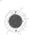
- FIG. 1 is a cross-sectional view of an optical fiber cable 1.
- the optical fiber cable 1 is a central-core-type cable without slotted rods.
- the optical fiber cable 1 includes a strength member 9, an outer sheath 13, and a cable core 15.
- the cable core 15 is formed of a plurality of optical fiber units 5 that are twisted together. Also, the optical fiber unit 5 is formed of a plurality of optical fiber tape core wires 3 that are twisted together.
- the optical fiber tape core wire 3 is an intermittently-bonded optical fiber tape core wire, which is bonded intermittently in a longitudinal direction. The optical fiber tape core wire 3 will be described in detail below.
- a presser winding 7 is provided on an outer periphery of the plurality of optical fiber tape core wires 3.
- the presser winding 7 is a tape-like member or a non-woven cloth that is arranged lengthwise, for example, collectively covering the outer periphery of the plurality of optical fiber tape core wires 3. That is, the presser winding 7 is disposed lengthwise on the outer periphery of the plurality of optical fiber tape core wires 3 such that a longitudinal direction of the presser winding 7 substantially corresponds with an axial direction of the optical fiber cable 1 and a width direction of the presser winding 7 substantially corresponds with a circumferential direction of the optical fiber cable 1.
- the cable core 15 includes the presser winding 7 that is wrapped around the plurality of optical fiber tape core wires 3.
- the strength members 9 are provided on both sides of the cable core 15. That is, a pair of the strength members 9 are provided at positions facing each other with the cable core 15 interposed therebetween.
- the rip cords 11 are provided in a direction substantially perpendicular to the facing direction of the strength members 9, facing each other with the cable core 15 interposed therebetween.
- the outer sheath 13 is provided on an outer periphery of the cable core 15.
- the strength members 9 and the rip cords 11 are embedded in the outer sheath 13. That is, the outer sheath 13 is provided so as to cover the cable core 15, the tension members 9, and so on.
- An outer shape of the outer sheath 13 is substantially a circle.
- the outer sheath 13 is made of polyolefin resin, for example.
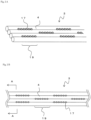
- FIG. 2A is a perspective view and FIG. 2B is a plan view showing the intermittently-bonded optical fiber tape core wire 3.
- the optical fiber tape core wire 3 includes a plurality of single-core optical fibers 4 that are coupled to each other while being arranged side by side.
- application holes are formed on a roller applicator and bonding resin is pushed out from an inner part of the roller applicator so that the optical fibers 4, which are arranged side by side, of the optical fiber tape core wire 3 are bonded from an upper surface of the optical fibers 4 into spaces between the optical fibers 4 at predetermined intervals.
- the number of optical fibers forming the optical fiber tape core wire 3 is not limited to the illustrated examples.
- the optical fibers 4 that are adjacent to each other are intermittently bonded to each other at coupling parts 19 at the predetermined intervals in a longitudinal direction of the optical fiber tape core wire 3.
- the coupling parts 19 that are adjacent to each other in a width direction are preferably disposed being displaced from one another in the longitudinal direction of the optical fiber tape core wire 3.
- the coupling parts 19 that are adjacent to each other are formed so as to be displaced a half pitch from one another in the longitudinal direction of the optical fiber tape core wire 3.
- the length and pitch of the coupling parts 19 are not limited to the illustrated examples.
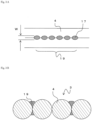
- FIG. 3A is an enlarged view of vicinity of the coupling part 19.
- the coupling part 19 includes a plurality of small bonding portions 17.
- the small bonding portions 17 are formed intermittently as dots, for example, with a predetermined pitch in the longitudinal direction of the optical fiber tape core wire 3, thereby having periodicity.
- a bonding length of each of the small bonding portions 17 in the longitudinal direction of the optical fiber tape core wire 3 is less than the pitch of the small bonding portions 17 within the coupling part 19.
- the small bonding portions 17 are separated from one another in the longitudinal direction of the optical fibers 4, and a non-bonded portion is formed between the small bonding portions 17. That is, in the optical fiber tape core wire 3, the adjacent optical fibers 4 are intermittently coupled in the longitudinal direction by the coupling parts 19, and amounts of resin of the coupling parts 19 are not uniform in the longitudinal direction of the optical fibers 4. That is, the amounts of resin at the coupling parts 19 are periodical but not uniform in the longitudinal direction of the optical fibers 4.
- FIG. 3B is a cross-sectional view taken along A-A line in FIG. 2B .
- the adjacent optical fibers 4 are coupled to each other with resin from both upper and lower surfaces of the optical fiber tape core wire 3.
- an amount of applied resin on an upper surface side of the optical fiber tape core wire 3 is different from an amount of applied resin on a lower surface side of the optical fiber tape core wire 3. That is, the amounts of resin at the coupling parts 19 are not only uneven along the longitudinal direction of the optical fibers 4 by parts but also uneven in regard to the upper and lower surfaces of the optical fiber tape core wire 3.
- the resin forming the coupling part 19 is ultraviolet curable resin, for example. Also, Young's modulus of the resin of the coupling parts of the resin forming the coupling parts 19 is preferably 130 MPa or less, or more preferably 80 MPa or less. IfYoung's modulus of the resin is too high, rigidity of the coupling part 19 increases, which increases stress applied to the optical fibers 4 when the resin contracts.
- Young's modulus of the resin forming the coupling parts 19 is low, the coupling parts 19 themselves can easily deform, thereby suppressing the stress applied to the optical fibers 4 low. However, ifYoung's modulus of the resin forming the coupling parts 19 is too low, the coupling part 19 (the small bonding portions 17) may crack. Thus, Young's modulus of the resin forming the coupling part 19 is preferably 40 MPa or more.
- Young's modulus of the resin forming the coupling part 19 is equal to or less than a predetermined value.
- Young's modulus of the resin forming the coupling part 19 is equal to or less than a predetermined value.
- the small bonding portions 17 may be disposed in other ways.
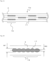
- the plurality of small bonding portions 17 may be continuously joined together at the coupling part 19. That is, also in such the case, although the amounts of resin at the coupling parts 19 are different and uneven in the longitudinal direction of the optical fibers 4 as shown in detail in FIG. 4B , the parts with the large amounts of resin and the parts with the small amounts of resin are periodical.
- Such the coupling part 19 may be obtained by applying adhesive in a form of the continuously joined plurality of small bonding portions 17, for example.
- such the coupling part 19 may be obtained by flow of the adhesive by controlling viscosity of the adhesive, intervals of application of the small bonding portions 17, time taken between application and curing, and conditions of start timing for curing, so that the small bonding portions 17 are joined together and cured before the small bonding portions 17 flow into a shape having a perfectly uniform width.
- the amounts of resin of the coupling parts 19 are uneven in the longitudinal direction of the optical fibers 4. Nevertheless, ifYoung's modulus of the resin forming the coupling parts 19 is low, the coupling parts 19 themselves deform easily and thus the stress applied to the optical fibers 4 can be suppressed low.
- Such the optical fiber tape core wire 3a can be manufactured by a method similar to the method for manufacturing the above-mentioned optical fiber tape core wire 3.
- the shape of the application holes formed on the roller applicator may be changed.
- the roller applicator having a plurality of small holes may be used to increase the amount of applied resin such that the adjacent small bonding portions 17 are joined together.
- the coupling part 19 may be formed in a shape having a substantially uniform width. Also in such the case, the width of the coupling part 19 becomes smaller at front and rear ends of the coupling part 19 and the amounts of resin of the coupling parts 19 are uneven in the longitudinal direction of the optical fibers 4. However, with low Young's modulus of the resin forming the coupling part 19, deformation of the coupling parts 19 themselves is easy, thereby suppressing the stress applied to the optical fibers 4 low.
- optical fibers 4 Although fibers having a core diameter of approximately 250 ⁇ m are commonly used, fibers having a core diameter of 200 ⁇ m may also be used. Such the optical fibers 4 having an outer diameter of 200 ⁇ m is often obtained by thinning a coating layer of the optical fiber having a core diameter of approximately 250 ⁇ m to have the outer diameter of 200 ⁇ m. By thinning the coating layer in this way, the optical fiber can be easily bent into a smaller diameter than the optical fiber having a core diameter of 250 ⁇ m. However, with low Young's modulus of the resin forming the coupling part 19, deformation of the coupling parts 19 themselves is easy, thereby suppressing the stress applied to the optical fibers 4 low.
- the influence of the stress applied to the optical fibers 4 from the coupling parts 19 may increase.
- Young's modulus of the resin forming the coupling part 19 deformation of the coupling parts 19 themselves is easy, thereby suppressing the stress applied to the optical fibers 4 low.
- a plurality of intermittently-bonded optical fiber tape core wires are produced, and their maximum transmission losses and cracks of the coupling parts are evaluated.
- Two types of optical fibers are used to form the optical fiber tape core wires.
- optical fibers categorized in ITU-T G.657 are used.
- the optical fiber categorized in ITU-T G.657 is formed by coloring an optical fiber bare wire having a diameter of 245 ⁇ m, and is a colored fiber having a mode field diameter of 8.6 ⁇ m and a diameter of 255 ⁇ m.
- optical fibers categorized in ITU-T G.654.E (Terawave ULL fibers by OFS) are used.
- the optical fiber categorized in ITU-T G.654 is formed by coloring an optical fiber bare wire having a diameter of 245 ⁇ m, and is a colored fiber having a mode field diameter of 12.4 ⁇ m and a diameter of 255 ⁇ m.
- the optical fiber tape core wire is produced by applying bonding resin with a roller applicator as described in above-mentioned Patent Document 2.
- each hole has a diameter of 0.3 mm and a pitch of the holes is 0.4 mm. Also, by adjusting the amount of resin, when viewed from the upper surface of the optical fiber tape core wire onto which the bonding resin is applied, the one with the small bonding portions that are separated from one another (see FIG. 2B ) and the one with the small bonding portions that are continuous (see FIG. 4A ) are produced.
- the maximum width of the applied resin (W in FIG. 3A ) is approximately 0.15 mm.
- the maximum width of the applied resin (W1 in FIG. 4B ) is approximately 0.2 mm and a width of a part where the adjacent applied resin are joined (W2 in FIG. 4B ) is approximately 0.12 mm.
- the level of Young's modulus of the bonding resin to bond the optical fibers is varied and the eight-core optical fiber tape core wires corresponding to each Young's modulus are produced. Young's modulus is measured as follows.
- a glass plate of 10 centimeters square is placed on a spin coater and, by controlling its rotation speed, an original ingredient is spread and applied onto the glass plate to be approximately 5 to 10 ⁇ m.
- the glass plate is then placed inside a purge box in which a nitrogen atmosphere is created, irradiated with ultraviolet light using an ultraviolet lamp with the iluminance of 1000 mW/cm 2 and irradiation dose of 1000 mJ/cm 2 to form a sheet.
- the sheet is held in an atmosphere of 25 °C 50 % RH set state for twelve hours, and samples are stamped out so that each sample is in a straight dumbbell shape having 75 mm length and 10 mm width.
- the obtained sample is pulled with a marked line of 25 mm at a pulling speed of 1 mm/min, and its Young's modulus is calculated from pulling force at 2.5 % distortion.
- Ten of the obtained optical fiber tape core wires are twisted together to form an eighty-core optical fiber unit wound by a plastic tape of 2 mm width. Also, 25 of the eighty-core optical fiber units are supplied and twisted together and then attached lengthwise with a water-absorbable non-woven cloth, rolled by a forming tool, which is then wound around by a nylon presser string to form a 2000-core cable core.
- the cable core formed as above together with strength members using steel wires of 1.8 mm diameter and rip cords for ripping the outer sheath are sheathed into a cylindrical shape by an outer sheath material to produce an optical fiber cable.
- the outer sheath material is low density polyethylene (LLDPE), and a thickness of the outer sheath is 3.0 mm.
- the minimum diameter of a turning sheave in a pass line through which the optical fiber tape core wire passes at the time of manufacturing the optical fiber unit described above and the minimum diameter of a turning sheave in a pass line through which the optical fiber unit passes at the time of manufacturing the cable core are 100 mm, respectively. Note that smaller the minimum diameter of the turning sheaves makes larger the bending force applied to the optical fiber tape core wire during the manufacturing process, which may cause cracking of the coupling parts.
Landscapes
- Physics & Mathematics (AREA)
- General Physics & Mathematics (AREA)
- Optics & Photonics (AREA)
- Engineering & Computer Science (AREA)
- Manufacturing & Machinery (AREA)
- Optical Fibers, Optical Fiber Cores, And Optical Fiber Bundles (AREA)
- Light Guides In General And Applications Therefor (AREA)
- Communication Cables (AREA)
- Surface Treatment Of Glass Fibres Or Filaments (AREA)
Abstract
Description
- The present invention relates to an optical fiber tape core wire with small transmission loss, and the like.
- As an optical fiber for high-speed transmission of large capacity data, an optical fiber tape core wire has been used to facilitate operations and accommodation in a cable. The optical fiber tape core wire includes a plurality of optical fibers that are arranged side by side in parallel and bonded to each other. In the optical fiber tape core wire, optical fibers arranged side by side are fixed with resin over an entire length thereof in some cases, and, in other cases, optical fibers are bonded to each other intermittently in a longitudinal direction (
Patent Document 1, for example). - Also, for manufacturing such the optical fiber tape core wire, there is a method in which resin is pushed out from a roller applicator having a plurality of application holes so that bonding resin can be applied into spaces between optical fibers (Patent Document 2, for example).
-
- [Patent Document 1]
Japanese Unexamined Patent Application Publication No. 2010-8923 JP-A-2010-8923 - [Patent Document 2]
Japanese Unexamined Patent Application Publication No. 2016-80849 JP-A-2016-80849 - The method described in Patent Document 2 uses a roller applicator. The roller applicator is a hollow roller having a plurality of application holes formed on an outer periphery surface thereof. The application hole is not one long continuous hole, for example, but is formed of a plurality of small holes that are aligned in a row along a circumferential direction. The application hole connects a space inside the roller applicator through to the outside.
- Bonding resin is continuously supplied into the roller applicator. A die is provided inside the roller applicator. By rolling the roller applicator, the bonding resin held on an inner surface of the roller applicator is pressed into a gap between the die and the inner surface of the roller applicator. When the application hole is positioned on an outer periphery side of the die, the die pushes the bonding resin out of the application hole to the outside.
- The bonding resin pushed out of the application hole is then applied into spaces between optical fibers that are fed being in contact with the roller applicator. At this time, the bonding resin applied from an upper part of the optical fibers flows down to a lower part side of the optical fibers due to force such as gravity and surface tension. Accordingly, the bonding resin is applied onto both sides of the optical fibers. When the optical fibers are arranged side by side and the bonding resin is applied on one side of the optical fibers as above, the bonding resin flows into the spaces between the optical fibers and goes around to the other side. This can make certain that the optical fibers are joined with each other.
- The optical fibers that have passed under the roller applicator are then irradiated with ultraviolet light, for example, to cure the bonding resin applied by the roller applicator. Accordingly, an optical fiber tape core wire is manufactured.
- However, in the above method, there is a difference between an amount of resin applied on an upper surface of the optical fibers and an amount of resin applied on a lower surface of the optical fibers. The bonding resin contracts in volume when being cured by ultraviolet light. Thus, the difference in the amounts of bonding resin between the upper and lower surfaces of the optical fiber tape core wire may lead to a difference in amounts of contraction of the resin. When the surface side with the larger amount of bonding resin contracts more, the optical fiber tape core wire receives a bending force.
- Also, if the bonding resin is applied into the space between the optical fibers by pushing out the bonding resin from the roller applicator having the application holes, the amount of applied bonding resin is not uniform and is uneven in a longitudinal direction of a coupling part. If the amount of applied bonding resin is uneven as above, the amount of contraction is also uneven in the longitudinal direction of the coupling part, which may cause the bending force.
- On the other hand, optical fibers categorized in ITU-T (International Telecommunication Union Telecommunication Standardization Sector) G.657 have been used for conventional optical fiber cables. Such optical fibers have a small increase in loss when being bent, and thus there is little influence of the above-mentioned bending force and deterioration in transmission loss is small.
- In contrast, optical fibers categorized in ITU-T G.652, which are relatively at low cost, or those categorized in ITU-T G.654.E, which enable long distance transmission and have large core diameters, experience relatively a larger increase in transmission loss when being bent. Thus, using such the optical fibers raises a problem of an increase in transmission loss due to the above-mentioned bending force.
- The present invention is made in view of the above problems. It is an object of the present invention to provide an optical fiber tape core wire and the like that can suppress an increase in loss when using optical fibers that experience a relatively larger increase in transmission loss when being bent.
- To achieve the above object, a first aspect of the present invention is an optical fiber tape core wire including a plurality of optical fibers that are arranged side by side and coupled to each other. The plurality of optical fibers adjacent to each other are intermittently coupled by coupling parts in a longitudinal direction. Amounts of resin of the coupling parts are not uniform in the longitudinal direction of the optical fibers, and Young's modulus of the resin of the coupling parts is 130 MPa or less.
- The Young's modulus of the resin of the coupling parts is more preferably 80 MPa or less.
- The adjacent optical fibers may be coupled at the coupling parts with the resin from both upper and lower surfaces of the optical fiber tape core wire.
- The amounts of the resin on the upper and lower surfaces of the optical fiber tape core wire may be formed unevenly at the coupling parts.
- The amounts of the resin at the coupling parts are periodical but may not be uniform in the longitudinal direction of the plurality of optical fibers.
- Each of the coupling parts includes a plurality of small bonding portions, and the plurality of small bonding portions may be joined continuously with each other.
- According to the first aspect of the present invention, Young's modulus of the resin of the coupling parts is deliberately made smaller. This can reduce influence of bending stress, which is applied to the optical fibers and is caused by unevenness of the amounts of contraction of the resin at different parts. Thus, low-cost optical fibers can be utilized.
- A second aspect of the present invention is an optical fiber cable in which the optical fiber tape core wire according to the first aspect of the present invention is used. The optical fiber cable includes a cable core formed of a plurality of the optical fiber tape core wires that are twisted together, and an outer sheath that is provided to coat the cable core.
- It is preferable that a maximum transmission loss at a wavelength of 1550 nm is less than 0.27 dB/km.
- The plurality of optical fibers may be categorized in ITU-T G.654.E.
- According to the second aspect of the present invention, it is possible to suppress an increase in loss, which is caused by unevenness of the amounts of contraction of the resin of the coupling parts at different parts. Thus, it is possible to utilize relatively low-cost optical fibers as well as optical fibers that enable further long-distance transmission.
- In particular, even if the optical fibers categorized in ITU-T G.654.E that experience a large increase in transmission loss when being bent are used, the maximum transmission loss at a wavelength of 1550 nm can be less than 0.27 dB/km.
- The present invention can provide an optical fiber tape core wire and the like that can suppress an increase in loss when using optical fibers that experience a relatively larger increase in transmission loss when being bent.
-
-
FIG. 1 is a cross-sectional view of anoptical fiber cable 1. -
FIG. 2A is a perspective view showing an optical fibertape core wire 3. -
FIG. 2B is a plan view showing the optical fibertape core wire 3. -
FIG. 3A is an enlarged view of acoupling part 19. -
FIG. 3B is a cross-sectional view taken along A-A line inFIG. 2B . -
FIG. 4A is a plan view showing an optical fiber tape core wire 3a. -
FIG. 4B is an enlarged view of thecoupling part 19. -
FIG. 5 is a plan view showing an optical fiber tape core wire 3b. - Hereinafter, an embodiment of the present invention will be described with reference to the accompanying drawings.
FIG. 1 is a cross-sectional view of anoptical fiber cable 1. Theoptical fiber cable 1 is a central-core-type cable without slotted rods. Theoptical fiber cable 1 includes astrength member 9, anouter sheath 13, and a cable core 15. - The cable core 15 is formed of a plurality of
optical fiber units 5 that are twisted together. Also, theoptical fiber unit 5 is formed of a plurality of optical fibertape core wires 3 that are twisted together. The optical fibertape core wire 3 is an intermittently-bonded optical fiber tape core wire, which is bonded intermittently in a longitudinal direction. The optical fibertape core wire 3 will be described in detail below. - A presser winding 7 is provided on an outer periphery of the plurality of optical fiber
tape core wires 3. The presser winding 7 is a tape-like member or a non-woven cloth that is arranged lengthwise, for example, collectively covering the outer periphery of the plurality of optical fibertape core wires 3. That is, the presser winding 7 is disposed lengthwise on the outer periphery of the plurality of optical fibertape core wires 3 such that a longitudinal direction of the presser winding 7 substantially corresponds with an axial direction of theoptical fiber cable 1 and a width direction of the presser winding 7 substantially corresponds with a circumferential direction of theoptical fiber cable 1. Note that the cable core 15 includes the presser winding 7 that is wrapped around the plurality of optical fibertape core wires 3. - On a cross section taken perpendicularly to the longitudinal direction of the
optical fiber cable 1, thestrength members 9 are provided on both sides of the cable core 15. That is, a pair of thestrength members 9 are provided at positions facing each other with the cable core 15 interposed therebetween. In addition, therip cords 11 are provided in a direction substantially perpendicular to the facing direction of thestrength members 9, facing each other with the cable core 15 interposed therebetween. - The
outer sheath 13 is provided on an outer periphery of the cable core 15. Thestrength members 9 and therip cords 11 are embedded in theouter sheath 13. That is, theouter sheath 13 is provided so as to cover the cable core 15, thetension members 9, and so on. An outer shape of theouter sheath 13 is substantially a circle. Theouter sheath 13 is made of polyolefin resin, for example. -
FIG. 2A is a perspective view andFIG. 2B is a plan view showing the intermittently-bonded optical fibertape core wire 3. The optical fibertape core wire 3 includes a plurality of single-coreoptical fibers 4 that are coupled to each other while being arranged side by side. For example, as described in Patent Document 2, application holes are formed on a roller applicator and bonding resin is pushed out from an inner part of the roller applicator so that theoptical fibers 4, which are arranged side by side, of the optical fibertape core wire 3 are bonded from an upper surface of theoptical fibers 4 into spaces between theoptical fibers 4 at predetermined intervals. The number of optical fibers forming the optical fibertape core wire 3 is not limited to the illustrated examples. - The
optical fibers 4 that are adjacent to each other are intermittently bonded to each other atcoupling parts 19 at the predetermined intervals in a longitudinal direction of the optical fibertape core wire 3. Also, thecoupling parts 19 that are adjacent to each other in a width direction are preferably disposed being displaced from one another in the longitudinal direction of the optical fibertape core wire 3. For example, it is preferable that thecoupling parts 19 that are adjacent to each other are formed so as to be displaced a half pitch from one another in the longitudinal direction of the optical fibertape core wire 3. The length and pitch of thecoupling parts 19 are not limited to the illustrated examples. -
FIG. 3A is an enlarged view of vicinity of thecoupling part 19. Thecoupling part 19 includes a plurality ofsmall bonding portions 17. Thesmall bonding portions 17 are formed intermittently as dots, for example, with a predetermined pitch in the longitudinal direction of the optical fibertape core wire 3, thereby having periodicity. - A bonding length of each of the
small bonding portions 17 in the longitudinal direction of the optical fibertape core wire 3 is less than the pitch of thesmall bonding portions 17 within thecoupling part 19. Thus, thesmall bonding portions 17 are separated from one another in the longitudinal direction of theoptical fibers 4, and a non-bonded portion is formed between thesmall bonding portions 17. That is, in the optical fibertape core wire 3, the adjacentoptical fibers 4 are intermittently coupled in the longitudinal direction by thecoupling parts 19, and amounts of resin of thecoupling parts 19 are not uniform in the longitudinal direction of theoptical fibers 4. That is, the amounts of resin at thecoupling parts 19 are periodical but not uniform in the longitudinal direction of theoptical fibers 4. -
FIG. 3B is a cross-sectional view taken along A-A line inFIG. 2B . At thecoupling parts 19, the adjacentoptical fibers 4 are coupled to each other with resin from both upper and lower surfaces of the optical fibertape core wire 3. At this time, at thecoupling part 19, an amount of applied resin on an upper surface side of the optical fibertape core wire 3 is different from an amount of applied resin on a lower surface side of the optical fibertape core wire 3. That is, the amounts of resin at thecoupling parts 19 are not only uneven along the longitudinal direction of theoptical fibers 4 by parts but also uneven in regard to the upper and lower surfaces of the optical fibertape core wire 3. - The resin forming the
coupling part 19 is ultraviolet curable resin, for example. Also, Young's modulus of the resin of the coupling parts of the resin forming thecoupling parts 19 is preferably 130 MPa or less, or more preferably 80 MPa or less. IfYoung's modulus of the resin is too high, rigidity of thecoupling part 19 increases, which increases stress applied to theoptical fibers 4 when the resin contracts. - On the other hand, if Young's modulus of the resin forming the
coupling parts 19 is low, thecoupling parts 19 themselves can easily deform, thereby suppressing the stress applied to theoptical fibers 4 low. However, ifYoung's modulus of the resin forming thecoupling parts 19 is too low, the coupling part 19 (the small bonding portions 17) may crack. Thus, Young's modulus of the resin forming thecoupling part 19 is preferably 40 MPa or more. - As described above, according to the present embodiment, Young's modulus of the resin forming the
coupling part 19 is equal to or less than a predetermined value. Thus, it is possible to reduce influence to theoptical fibers 4 of the unevenness of an amount of contraction of the resin by the parts in the longitudinal direction or by the upper and lower surfaces of thecoupling parts 19. For this reason, it is possible to suppress an increase in transmission loss when low-pricedoptical fibers 4 are used. - Although an example in which the
small bonding portions 17 are disposed intermittently in the longitudinal direction of thecoupling parts 19 is shown in the above embodiment, thesmall bonding portions 17 may be disposed in other ways. For example, as in an optical fiber tape core wire 3a shown inFIG. 4A , the plurality ofsmall bonding portions 17 may be continuously joined together at thecoupling part 19. That is, also in such the case, although the amounts of resin at thecoupling parts 19 are different and uneven in the longitudinal direction of theoptical fibers 4 as shown in detail inFIG. 4B , the parts with the large amounts of resin and the parts with the small amounts of resin are periodical. Such thecoupling part 19 may be obtained by applying adhesive in a form of the continuously joined plurality ofsmall bonding portions 17, for example. Or, such thecoupling part 19 may be obtained by flow of the adhesive by controlling viscosity of the adhesive, intervals of application of thesmall bonding portions 17, time taken between application and curing, and conditions of start timing for curing, so that thesmall bonding portions 17 are joined together and cured before thesmall bonding portions 17 flow into a shape having a perfectly uniform width. For such the optical fibertape core wire 3, the amounts of resin of thecoupling parts 19 are uneven in the longitudinal direction of theoptical fibers 4. Nevertheless, ifYoung's modulus of the resin forming thecoupling parts 19 is low, thecoupling parts 19 themselves deform easily and thus the stress applied to theoptical fibers 4 can be suppressed low. - Such the optical fiber tape core wire 3a can be manufactured by a method similar to the method for manufacturing the above-mentioned optical fiber
tape core wire 3. For example, the shape of the application holes formed on the roller applicator may be changed. Alternatively, the roller applicator having a plurality of small holes may be used to increase the amount of applied resin such that the adjacentsmall bonding portions 17 are joined together. - Also, for the
coupling part 19, it is not always necessary to apply the resin to form the plurality of separate or continuoussmall bonding portions 17. For example, as in an optical fiber tape core wire 3b shown inFIG. 5 , instead of being formed of the plurality ofsmall bonding portions 17, thecoupling part 19 may be formed in a shape having a substantially uniform width. Also in such the case, the width of thecoupling part 19 becomes smaller at front and rear ends of thecoupling part 19 and the amounts of resin of thecoupling parts 19 are uneven in the longitudinal direction of theoptical fibers 4. However, with low Young's modulus of the resin forming thecoupling part 19, deformation of thecoupling parts 19 themselves is easy, thereby suppressing the stress applied to theoptical fibers 4 low. - For the
optical fibers 4, although fibers having a core diameter of approximately 250 µm are commonly used, fibers having a core diameter of 200 µm may also be used. Such theoptical fibers 4 having an outer diameter of 200 µm is often obtained by thinning a coating layer of the optical fiber having a core diameter of approximately 250 µm to have the outer diameter of 200 µm. By thinning the coating layer in this way, the optical fiber can be easily bent into a smaller diameter than the optical fiber having a core diameter of 250 µm. However, with low Young's modulus of the resin forming thecoupling part 19, deformation of thecoupling parts 19 themselves is easy, thereby suppressing the stress applied to theoptical fibers 4 low. - Also, as denser the optical fibers are packed, such as 3456 cores or even 6912 cores, the influence of the stress applied to the
optical fibers 4 from thecoupling parts 19 may increase. At this time, with low Young's modulus of the resin forming thecoupling part 19, deformation of thecoupling parts 19 themselves is easy, thereby suppressing the stress applied to theoptical fibers 4 low. - A plurality of intermittently-bonded optical fiber tape core wires are produced, and their maximum transmission losses and cracks of the coupling parts are evaluated. Two types of optical fibers are used to form the optical fiber tape core wires.
- For the optical fibers that experience a small increase in transmission loss due to stress, optical fibers categorized in ITU-T G.657 are used. The optical fiber categorized in ITU-T G.657 is formed by coloring an optical fiber bare wire having a diameter of 245 µm, and is a colored fiber having a mode field diameter of 8.6 µm and a diameter of 255 µm.
- In comparison, optical fibers categorized in ITU-T G.654.E (Terawave ULL fibers by OFS) are used. The optical fiber categorized in ITU-T G.654 is formed by coloring an optical fiber bare wire having a diameter of 245 µm, and is a colored fiber having a mode field diameter of 12.4 µm and a diameter of 255 µm.
- Eight of the colored fibers are bonded intermittently to produce an eight-core intermittently-bonded optical fiber tape core wire. The optical fiber tape core wire is produced by applying bonding resin with a roller applicator as described in above-mentioned Patent Document 2.
- For discharge holes on the roller applicator, each hole has a diameter of 0.3 mm and a pitch of the holes is 0.4 mm. Also, by adjusting the amount of resin, when viewed from the upper surface of the optical fiber tape core wire onto which the bonding resin is applied, the one with the small bonding portions that are separated from one another (see
FIG. 2B ) and the one with the small bonding portions that are continuous (seeFIG. 4A ) are produced. - For the separated small bonding portions, the maximum width of the applied resin (W in
FIG. 3A ) is approximately 0.15 mm. On the other hand, for the continuous small bonding portions that are adj acent to each other in the longitudinal direction, the maximum width of the applied resin (W1 inFIG. 4B ) is approximately 0.2 mm and a width of a part where the adjacent applied resin are joined (W2 inFIG. 4B ) is approximately 0.12 mm. - The level of Young's modulus of the bonding resin to bond the optical fibers is varied and the eight-core optical fiber tape core wires corresponding to each Young's modulus are produced. Young's modulus is measured as follows.
- First, a glass plate of 10 centimeters square is placed on a spin coater and, by controlling its rotation speed, an original ingredient is spread and applied onto the glass plate to be approximately 5 to 10 µm. The glass plate is then placed inside a purge box in which a nitrogen atmosphere is created, irradiated with ultraviolet light using an ultraviolet lamp with the iluminance of 1000 mW/cm2 and irradiation dose of 1000 mJ/cm2 to form a sheet. The sheet is held in an atmosphere of 25 °C 50 % RH set state for twelve hours, and samples are stamped out so that each sample is in a straight dumbbell shape having 75 mm length and 10 mm width. The obtained sample is pulled with a marked line of 25 mm at a pulling speed of 1 mm/min, and its Young's modulus is calculated from pulling force at 2.5 % distortion.
- Ten of the obtained optical fiber tape core wires are twisted together to form an eighty-core optical fiber unit wound by a plastic tape of 2 mm width. Also, 25 of the eighty-core optical fiber units are supplied and twisted together and then attached lengthwise with a water-absorbable non-woven cloth, rolled by a forming tool, which is then wound around by a nylon presser string to form a 2000-core cable core.
- The cable core formed as above together with strength members using steel wires of 1.8 mm diameter and rip cords for ripping the outer sheath are sheathed into a cylindrical shape by an outer sheath material to produce an optical fiber cable. The outer sheath material is low density polyethylene (LLDPE), and a thickness of the outer sheath is 3.0 mm.
- The minimum diameter of a turning sheave in a pass line through which the optical fiber tape core wire passes at the time of manufacturing the optical fiber unit described above and the minimum diameter of a turning sheave in a pass line through which the optical fiber unit passes at the time of manufacturing the cable core are 100 mm, respectively. Note that smaller the minimum diameter of the turning sheaves makes larger the bending force applied to the optical fiber tape core wire during the manufacturing process, which may cause cracking of the coupling parts.
- For each of the obtained optical fiber cables, transmission loss at a wavelength of 1550 nm is measured. Also, the optical fiber tape core wire is taken out of the optical fiber cable to check if there are any cracks in the coupling parts within a 10 meters long optical fiber tape core wire. The one having two or more consecutive cracked coupling parts in a same line in the longitudinal direction is regarded as "Failed". The results are shown in Table 1 and Table 2.
[Table 1] Working Example 1 Working Example 2 Working Example 3 Working Example 4 Working Example 5 Working Example 6 Working Example 7 Optical Fiber G.654.E G.654.E G.654.E G.654.E G.654.E G.654.E G.654.E Shape of Small Bonding Portions Continuou s Continuou s Continuou s Separate d Separate d Separate d Continuou s Young's Modulus of Bonding Resin (MPa) 41 77 128 41 77 128 55 Maximum Transmissio n Loss of 0.27dB/km or more None None None None None None None Maximum Transmissio n Loss of 0.23dB/km or more None None Exist None None Exist None Two Consecutive Cracks of Coupling Parts None None None None None None None [Table 2] Comparativ e Example 1 Comparativ e Example 2 Comparativ e Example 3 Comparativ e Example 4 Comparativ e Example 5 Comparativ e Example 6 Optical Fiber G.654.E G.654.E G.654.E G.654.E G.657 G.657 Shape of Small Bonding Portions Continuous Separated Continuous Separated Continuous Separated Young's Modulus of Bonding Resin (MPa) 30 30 155 155 155 155 Maximum Transmissio n Loss 0.27dB/km or more None None Exist Exist None None Maximum Transmissio n Loss of 0.23dB/km or more None None Exist Exist None None Two Consecutive Cracks of Coupling Parts Exist Exist None None None None - In any of Working Examples 1 to 7, there is no two-consecutive cracks of the bonding resin, and the maximum transmission loss is less than 0.27 dB/km even when the optical fibers categorized in ITU-T G. 654.E, which experience a large increase in transmission loss when being bent, are used. In particular, in Working Examples 1, 2, 4, 5, and 7 where Young's modulus of the bonding resin is 80 MPa or less (41 MPa, 55 MPa, and 77 MPa), the maximum transmission loss is less than 0.23 dB/km.
- On the other hand, two consecutive cracks of the bonding resin occur in Comparative Examples 1 and 2 in which Young's modulus of the bonding resin is less than 40 MPa. Also, in Comparative Examples 3 and 4, although there is no two-consecutive cracks of the bonding resin, Young's modulus of the bonding resin is more than 130 MPa and thus the maximum transmission loss is 0.27 dB/km or more. Note that for the optical fibers categorized in ITU-T G.657, the maximum transmission loss is less than 0.23 dB/km even if the Young's modulus of the bonding resin is more than 130 MPa.
- Although the embodiments of the present invention have been described referring to the attached drawings, the technical scope of the present invention is not limited to the embodiments described above. It is obvious that persons skilled in the art can think out various examples of changes or modifications within the scope of the technical idea disclosed in the claims, and it will be understood that they naturally belong to the technical scope of the present invention.
-
- 1
- optical fiber cable
- 3, 3a, 3b
- optical fiber tape core wire
- 4
- optical fiber
- 5
- optical fiber unit
- 7
- presser winding
- 9
- strength member
- 11
- rip cord
- 13
- outer sheath
- 15
- cable core
- 17
- small bonding portion
- 19
- coupling part
Claims (9)
- An optical fiber tape core wire comprising:a plurality of optical fibers that are arranged side by side and coupled to each other, whereinthe plurality of optical fibers adjacent to each other are intermittently coupled by coupling parts in a longitudinal direction;amounts of resin of the coupling parts are not uniform in a longitudinal direction of the plurality of optical fibers; andYoung's modulus of the resin of the coupling parts is 130 MPa or less.
- The optical fiber tape core wire according to claim 1, wherein
Young's modulus of the resin of the coupling parts is 80 MPa or less. - The optical fiber tape core wire according to claim 1, wherein
the optical fibers adjacent to each other are coupled at the coupling parts with the resin from both upper and lower surfaces of the optical fiber tape core wire. - The optical fiber tape core wire according to claim 3, wherein
the amounts of the resin on the upper and lower surfaces of the optical fiber tape core wire are formed unevenly at the coupling parts. - The optical fiber tape core wire according to claim 1, wherein
the amounts of the resin at the coupling parts are periodical but are uneven in the longitudinal direction of the plurality of optical fibers. - The optical fiber tape core wire according to claim 1, wherein
each of the coupling parts includes a plurality of small bonding portions, the plurality of small bonding portions being joined continuously with each other. - An optical fiber cable in which the optical fiber tape core wire according to any of claims 1 to 6 is used, the optical fiber cable comprising:a cable core formed of a plurality of the optical fiber tape core wires that are twisted together; andan outer sheath that is provided to coat the cable core.
- The optical fiber cable according to claim 7, wherein
a maximum transmission loss at a wavelength of 1550 nm is less than 0.27 dB/km. - The optical fiber cable according to claim 7, wherein
the plurality of optical fibers are categorized in ITU-T G.654.E.
Applications Claiming Priority (2)
| Application Number | Priority Date | Filing Date | Title |
|---|---|---|---|
| JP2020119436A JP7084449B2 (en) | 2020-07-10 | 2020-07-10 | Optical fiber tape core wire, optical fiber cable |
| PCT/JP2021/025149 WO2022009798A1 (en) | 2020-07-10 | 2021-07-02 | Optical fiber tape core wire and optical fiber cable |
Publications (2)
| Publication Number | Publication Date |
|---|---|
| EP4180850A1 true EP4180850A1 (en) | 2023-05-17 |
| EP4180850A4 EP4180850A4 (en) | 2024-07-31 |
Family
ID=79552611
Family Applications (1)
| Application Number | Title | Priority Date | Filing Date |
|---|---|---|---|
| EP21838281.0A Pending EP4180850A4 (en) | 2020-07-10 | 2021-07-02 | FIBER OPTIC RIBBON CORE WIRE AND FIBER OPTIC CABLE |
Country Status (5)
| Country | Link |
|---|---|
| US (1) | US20230123198A1 (en) |
| EP (1) | EP4180850A4 (en) |
| JP (1) | JP7084449B2 (en) |
| TW (1) | TWI802927B (en) |
| WO (1) | WO2022009798A1 (en) |
Cited By (2)
| Publication number | Priority date | Publication date | Assignee | Title |
|---|---|---|---|---|
| EP4215965A4 (en) * | 2020-09-16 | 2024-03-06 | Sumitomo Electric Industries, Ltd. | Optical fiber ribbon and sub-tape-type optical fiber ribbon |
| EP4524630A4 (en) * | 2022-05-11 | 2025-09-10 | Sumitomo Electric Industries | OPTICAL FIBER RIBBON |
Families Citing this family (9)
| Publication number | Priority date | Publication date | Assignee | Title |
|---|---|---|---|---|
| KR102941745B1 (en) * | 2022-07-21 | 2026-03-23 | 엘에스전선 주식회사 | Optical Fiber Ribbon |
| CN115144956B (en) * | 2022-09-06 | 2022-11-04 | 江苏中天科技股份有限公司 | A flexible optical fiber ribbon and ribbon optical cable |
| CN115144957B (en) * | 2022-09-06 | 2022-11-04 | 江苏中天科技股份有限公司 | A kind of orientable winding flexible optical fiber ribbon and optical fiber cable thereof |
| GB2626059A (en) * | 2022-09-06 | 2024-07-10 | Jiangsu Zhongtian Technology Co Ltd | Flexible optical fiber ribbon and ribbon optical fiber cable |
| KR102676816B1 (en) * | 2022-12-23 | 2024-06-19 | 엘에스전선 주식회사 | Optical Fiber Ribbon |
| EP4767103A1 (en) * | 2023-08-22 | 2026-07-01 | Corning Research & Development Corporation | INTERMITTENTLY BONDED FIBERGLASS TAPE WITH VARIABLE BONDING DISTANCE |
| WO2025245487A1 (en) * | 2024-05-24 | 2025-11-27 | Belden Inc. | An optical fiber ribbon with bond portions providing flexibility and reduced stress between bonded optical fibers |
| CN118707670A (en) * | 2024-06-03 | 2024-09-27 | 南京华信藤仓光通信有限公司 | Bonding type optical fiber ribbon and its preparation device and preparation method |
| CN121386118B (en) * | 2025-12-24 | 2026-03-20 | 长飞光纤光缆股份有限公司 | An optical fiber ribbon that is easy to identify and detect optically and its manufacturing method |
Family Cites Families (22)
| Publication number | Priority date | Publication date | Assignee | Title |
|---|---|---|---|---|
| JP2820691B2 (en) * | 1988-03-31 | 1998-11-05 | 株式会社フジクラ | Split type optical fiber tape |
| JPH10160987A (en) * | 1996-12-02 | 1998-06-19 | Sumitomo Electric Ind Ltd | Optical fiber unit and optical cable |
| JPH11258431A (en) * | 1998-03-13 | 1999-09-24 | Hitachi Cable Ltd | Optical fiber bundle and optical fiber cable |
| WO2003098307A1 (en) * | 2002-05-17 | 2003-11-27 | Sumitomo Electric Industries, Ltd. | Tape-like optical fiber core, production method therefor, tape core-carrying connector, tape core-carrying optical fiber array, and optical wiring system |
| JP4619424B2 (en) | 2008-06-30 | 2011-01-26 | 日本電信電話株式会社 | Fiber optic cable |
| JP5066205B2 (en) * | 2010-03-04 | 2012-11-07 | 株式会社フジクラ | Optical fiber strand tape core manufacturing method and optical fiber core tape core manufacturing apparatus |
| JP5391296B2 (en) * | 2012-03-02 | 2014-01-15 | 株式会社フジクラ | Optical fiber tape core and optical fiber cable storing the optical fiber core |
| JP6169060B2 (en) | 2014-10-16 | 2017-07-26 | 古河電気工業株式会社 | Optical fiber ribbon manufacturing method and optical fiber ribbon manufacturing apparatus |
| EP3330760B1 (en) * | 2015-07-31 | 2024-10-30 | Sumitomo Electric Industries, Ltd. | Optical fiber cable |
| JP6569429B2 (en) * | 2015-09-25 | 2019-09-04 | 住友電気工業株式会社 | Optical fiber ribbon |
| WO2017094560A1 (en) * | 2015-12-01 | 2017-06-08 | 古河電気工業株式会社 | Optical fiber ribbon core-wire and optical fiber cable |
| US10989888B2 (en) * | 2016-02-02 | 2021-04-27 | Ofs Fitel, Llc | Flexible ribbon structure and method for making |
| JP6188097B2 (en) * | 2016-05-20 | 2017-08-30 | 日本電信電話株式会社 | Intermittently bonded optical fiber tape and optical cable using the same |
| JP6586925B2 (en) * | 2016-06-13 | 2019-10-09 | 住友電気工業株式会社 | Fiber optic cable |
| PL3491441T3 (en) * | 2016-07-27 | 2020-10-05 | Prysmian S.P.A. | Flexible optical-fiber ribbon |
| WO2018031436A1 (en) * | 2016-08-08 | 2018-02-15 | Corning Optical Communications LLC | Flexible optical fiber ribbon with intermittently bonded polymer layers |
| JP6967472B2 (en) * | 2017-06-02 | 2021-11-17 | 株式会社フジクラ | Fiber optic cable |
| EP3627197B1 (en) * | 2017-07-03 | 2022-11-09 | Nippon Telegraph and Telephone Corporation | Optical fiber and optical transmission system |
| US11256051B2 (en) * | 2018-01-15 | 2022-02-22 | Prysmian S.P.A. | Flexible optical-fiber ribbon |
| CN111989602A (en) * | 2018-01-15 | 2020-11-24 | 普睿司曼股份公司 | Manufacturing method of flexible optical fiber ribbon and said ribbon |
| CN111175887A (en) * | 2020-02-13 | 2020-05-19 | 江苏亨通光电股份有限公司 | Optical fiber ribbon, optical cable, and method for manufacturing optical fiber ribbon |
| US11592631B2 (en) * | 2020-03-04 | 2023-02-28 | Sterlite Technologies Limited | Optical fibre ribbon having bond shape |
-
2020
- 2020-07-10 JP JP2020119436A patent/JP7084449B2/en active Active
-
2021
- 2021-07-02 WO PCT/JP2021/025149 patent/WO2022009798A1/en not_active Ceased
- 2021-07-02 EP EP21838281.0A patent/EP4180850A4/en active Pending
- 2021-07-06 TW TW110124766A patent/TWI802927B/en active
-
2022
- 2022-12-15 US US18/081,998 patent/US20230123198A1/en not_active Abandoned
Cited By (3)
| Publication number | Priority date | Publication date | Assignee | Title |
|---|---|---|---|---|
| EP4215965A4 (en) * | 2020-09-16 | 2024-03-06 | Sumitomo Electric Industries, Ltd. | Optical fiber ribbon and sub-tape-type optical fiber ribbon |
| US12379558B2 (en) | 2020-09-16 | 2025-08-05 | Sumitomo Electric Industries, Ltd. | Optical fiber ribbon and sub-tape-type optical fiber ribbon |
| EP4524630A4 (en) * | 2022-05-11 | 2025-09-10 | Sumitomo Electric Industries | OPTICAL FIBER RIBBON |
Also Published As
| Publication number | Publication date |
|---|---|
| JP7084449B2 (en) | 2022-06-14 |
| TW202208911A (en) | 2022-03-01 |
| US20230123198A1 (en) | 2023-04-20 |
| TWI802927B (en) | 2023-05-21 |
| WO2022009798A1 (en) | 2022-01-13 |
| EP4180850A4 (en) | 2024-07-31 |
| JP2022016133A (en) | 2022-01-21 |
Similar Documents
| Publication | Publication Date | Title |
|---|---|---|
| US20230123198A1 (en) | Optical fiber ribbon and optical fiber cable | |
| RU2759664C1 (en) | Method for manufacturing flexible fibre-optic tape and tape | |
| JP5162645B2 (en) | Optical fiber ribbon manufacturing method, manufacturing apparatus, optical fiber ribbon and optical fiber cable | |
| CN1537246A (en) | Optical Fiber Ribbon Cable Core Wire | |
| EP3910393B1 (en) | Optical fiber cable and cable core production method | |
| EP3923052B1 (en) | An intermittently coupled-type optical fiber ribbon and a method for manufacturing thereof | |
| US20200386961A1 (en) | Flexible Optical-Fiber Ribbon | |
| DE2755734C2 (en) | Manufacturing process for a communication cable containing a plurality of optical fibers and a cable manufactured according to this process | |
| JP2025541904A (en) | Fiber Optic Ribbon | |
| JP7680569B2 (en) | Optical fiber ribbon and slotless optical cable | |
| JP7753386B2 (en) | Optical fiber rollable ribbon with low Young's modulus bonding matrix material. | |
| JP7479225B2 (en) | Optical fiber ribbon, optical fiber cable | |
| US12601883B2 (en) | Optical fiber ribbon and slotless optical cable | |
| WO2022131099A1 (en) | Optical fiber ribbon | |
| US20250189742A1 (en) | Optical fiber ribbon and slot-less optical cable | |
| EP4560371A1 (en) | Optical fiber ribbon | |
| JPH09113773A (en) | Optical fiber ribbon | |
| JP7613003B2 (en) | Optical fiber assemblage manufacturing method and manufacturing device | |
| JP2021189231A (en) | Coated optical fiber, optical fiber ribbon, and optical fiber cable | |
| JP2005321645A (en) | Tape type optical fiber | |
| US10268008B2 (en) | Plastic optical fiber ribbon | |
| DE69837304T2 (en) | Sheathed optical fiber and manufacturing process | |
| US20240337801A1 (en) | Unitary optical fibre ribbon | |
| JP2002116358A (en) | Optical fiber ribbon and manufacturing method thereof | |
| JP2000292664A (en) | Method and apparatus for manufacturing optical fiber ribbon |
Legal Events
| Date | Code | Title | Description |
|---|---|---|---|
| STAA | Information on the status of an ep patent application or granted ep patent |
Free format text: STATUS: THE INTERNATIONAL PUBLICATION HAS BEEN MADE |
|
| PUAI | Public reference made under article 153(3) epc to a published international application that has entered the european phase |
Free format text: ORIGINAL CODE: 0009012 |
|
| STAA | Information on the status of an ep patent application or granted ep patent |
Free format text: STATUS: REQUEST FOR EXAMINATION WAS MADE |
|
| 17P | Request for examination filed |
Effective date: 20221219 |
|
| AK | Designated contracting states |
Kind code of ref document: A1 Designated state(s): AL AT BE BG CH CY CZ DE DK EE ES FI FR GB GR HR HU IE IS IT LI LT LU LV MC MK MT NL NO PL PT RO RS SE SI SK SM TR |
|
| DAV | Request for validation of the european patent (deleted) | ||
| DAX | Request for extension of the european patent (deleted) | ||
| A4 | Supplementary search report drawn up and despatched |
Effective date: 20240627 |
|
| RIC1 | Information provided on ipc code assigned before grant |
Ipc: G02B 6/44 20060101AFI20240621BHEP |