EP4180773A1 - System and method for separating avionics charts into a plurality of display panels - Google Patents
System and method for separating avionics charts into a plurality of display panels Download PDFInfo
- Publication number
- EP4180773A1 EP4180773A1 EP22207164.9A EP22207164A EP4180773A1 EP 4180773 A1 EP4180773 A1 EP 4180773A1 EP 22207164 A EP22207164 A EP 22207164A EP 4180773 A1 EP4180773 A1 EP 4180773A1
- Authority
- EP
- European Patent Office
- Prior art keywords
- display panels
- chart data
- display
- data
- aircraft
- Prior art date
- Legal status (The legal status is an assumption and is not a legal conclusion. Google has not performed a legal analysis and makes no representation as to the accuracy of the status listed.)
- Pending
Links
Images

Classifications
-
- G—PHYSICS
- G06—COMPUTING OR CALCULATING; COUNTING
- G06F—ELECTRIC DIGITAL DATA PROCESSING
- G06F3/00—Input arrangements for transferring data to be processed into a form capable of being handled by the computer; Output arrangements for transferring data from processing unit to output unit, e.g. interface arrangements
- G06F3/14—Digital output to display device ; Cooperation and interconnection of the display device with other functional units
- G06F3/1423—Digital output to display device ; Cooperation and interconnection of the display device with other functional units controlling a plurality of local displays, e.g. CRT and flat panel display
-
- B—PERFORMING OPERATIONS; TRANSPORTING
- B64—AIRCRAFT; AVIATION; COSMONAUTICS
- B64D—EQUIPMENT FOR FITTING IN OR TO AIRCRAFT; FLIGHT SUITS; PARACHUTES; ARRANGEMENT OR MOUNTING OF POWER PLANTS OR PROPULSION TRANSMISSIONS IN AIRCRAFT
- B64D43/00—Arrangements or adaptations of instruments
-
- G—PHYSICS
- G08—SIGNALLING
- G08G—TRAFFIC CONTROL SYSTEMS
- G08G5/00—Traffic control systems for aircraft
- G08G5/20—Arrangements for acquiring, generating, sharing or displaying traffic information
- G08G5/21—Arrangements for acquiring, generating, sharing or displaying traffic information located onboard the aircraft
-
- G—PHYSICS
- G08—SIGNALLING
- G08G—TRAFFIC CONTROL SYSTEMS
- G08G5/00—Traffic control systems for aircraft
- G08G5/30—Flight plan management
-
- G—PHYSICS
- G09—EDUCATION; CRYPTOGRAPHY; DISPLAY; ADVERTISING; SEALS
- G09G—ARRANGEMENTS OR CIRCUITS FOR CONTROL OF INDICATING DEVICES USING STATIC MEANS TO PRESENT VARIABLE INFORMATION
- G09G5/00—Control arrangements or circuits for visual indicators common to cathode-ray tube indicators and other visual indicators
- G09G5/36—Control arrangements or circuits for visual indicators common to cathode-ray tube indicators and other visual indicators characterised by the display of a graphic pattern, e.g. using an all-points-addressable [APA] memory
- G09G5/38—Control arrangements or circuits for visual indicators common to cathode-ray tube indicators and other visual indicators characterised by the display of a graphic pattern, e.g. using an all-points-addressable [APA] memory with means for controlling the display position
-
- G—PHYSICS
- G09—EDUCATION; CRYPTOGRAPHY; DISPLAY; ADVERTISING; SEALS
- G09G—ARRANGEMENTS OR CIRCUITS FOR CONTROL OF INDICATING DEVICES USING STATIC MEANS TO PRESENT VARIABLE INFORMATION
- G09G2300/00—Aspects of the constitution of display devices
- G09G2300/02—Composition of display devices
- G09G2300/026—Video wall, i.e. juxtaposition of a plurality of screens to create a display screen of bigger dimensions
-
- G—PHYSICS
- G09—EDUCATION; CRYPTOGRAPHY; DISPLAY; ADVERTISING; SEALS
- G09G—ARRANGEMENTS OR CIRCUITS FOR CONTROL OF INDICATING DEVICES USING STATIC MEANS TO PRESENT VARIABLE INFORMATION
- G09G2340/00—Aspects of display data processing
- G09G2340/04—Changes in size, position or resolution of an image
-
- G—PHYSICS
- G09—EDUCATION; CRYPTOGRAPHY; DISPLAY; ADVERTISING; SEALS
- G09G—ARRANGEMENTS OR CIRCUITS FOR CONTROL OF INDICATING DEVICES USING STATIC MEANS TO PRESENT VARIABLE INFORMATION
- G09G2340/00—Aspects of display data processing
- G09G2340/14—Solving problems related to the presentation of information to be displayed
- G09G2340/145—Solving problems related to the presentation of information to be displayed related to small screens
-
- G—PHYSICS
- G09—EDUCATION; CRYPTOGRAPHY; DISPLAY; ADVERTISING; SEALS
- G09G—ARRANGEMENTS OR CIRCUITS FOR CONTROL OF INDICATING DEVICES USING STATIC MEANS TO PRESENT VARIABLE INFORMATION
- G09G2380/00—Specific applications
- G09G2380/12—Avionics applications
Definitions
- a method for separating avionics charts into a plurality of display panels includes receiving chart data for a virtual avionics chart.
- the method includes determining whether the received chart data exceeds a predetermined threshold.
- the method includes generating a plurality of display panels if the received chart data exceeds the predetermined threshold.
- the method includes determining one or more buffer lengths for the generated plurality of display panels.
- the method includes generating a plurality of output files based on the generated plurality of display panels and the determined one or more buffer lengths.
- the method may include providing the plurality of output files to an on-board aircraft controller for display on one or more display devices of an aircraft.
- the determine whether the received chart data exceeds a predetermined threshold may include comparing a data size of the received chart data to a predetermined data size threshold.
- the predetermined data size threshold may be between 1.2 Mb and 1.5 Mb.
- the predetermined data size threshold may be 1.3 Mb.
- the generate a plurality of display panels if the received chart data exceeds the predetermined threshold may further include determining one or more fold locations; determining one or more fold sizes; and assigning one or more fold numbers to one or more sections based on at least one of one or more x-values or one or more y-values.
- the one or more buffer lengths may be 1.00 inches.
- the method may further include determining whether chart data of the generated plurality of output files exceeds a predetermined threshold and adjusting a fold size of the one or more display panels if the chart data of the generated plurality of output files for the one or more display panels exceeds the predetermined threshold.
- a system for separating avionics charts into a plurality of display panels includes one or more controllers including one or more processors configured to execute a set of program instructions stored in a memory, the set of program instructions configured to cause the one or more processors to: receive chart data for a virtual avionics chart; determine whether the received chart data exceeds a predetermined threshold; generate a plurality of display panels if the received chart data exceeds the predetermined threshold; determine one or more buffer lengths for the generated plurality of display panels; and generate a plurality of output files based on the generated plurality of display panels and the determined one or more buffer lengths.
- the one or more controllers may be configured to provide the plurality of output files to an on-board aircraft controller for display on one or more display devices of an aircraft.
- the determine whether the received chart data exceeds a predetermined threshold may include comparing a data size of the received chart data to a predetermined data size threshold.
- the predetermined data size threshold may be between 1.2 Mb and 1.5 Mb.
- the predetermined data size threshold may be 1.3 Mb.
- the generate a plurality of display panels if the received chart data exceeds the predetermined threshold may further include determining one or more fold locations; determining one or more fold sizes; and assigning one or more fold numbers to one or more sections based on at least one of one or more x-values or one or more y-values.
- the method may further include determining whether chart data of the generated plurality of output files exceeds a predetermined threshold and adjusting a fold size of the one or more display panels if the chart data of the generated plurality of output files for the one or more display panels exceeds the predetermined threshold.
- a letter following a reference numeral is intended to reference an embodiment of the feature or element that may be similar, but not necessarily identical, to a previously described element or feature bearing the same reference numeral (e.g., 1, 1a, 1b).
- reference numeral e.g. 1, 1a, 1b
- Such shorthand notations are used for purposes of convenience only and should not be construed to limit the disclosure in any way unless expressly stated to the contrary.
- any reference to “one embodiment” or “some embodiments” means that a particular element, feature, structure, or characteristic described in connection with the embodiment is included in at least one embodiment disclosed herein.
- the appearances of the phrase “in some embodiments” in various places in the specification are not necessarily all referring to the same embodiment, and embodiments may include one or more of the features expressly described or inherently present herein, or any combination of or sub-combination of two or more such features, along with any other features which may not necessarily be expressly described or inherently present in the instant disclosure.
- FIGS. 1A-5 generally illustrate a system and method for separating avionics charts into a plurality of display panels, in accordance with one or more embodiments of the present disclosure.
- Aeronautical charts are widely used for air navigation.
- the Federal Aviation Administration publishes charts for each stage of Visual Flight Rules (VFR) and Instrument Flight Rules (IFR) air navigation including training, planning, and departures, enroute (for low and high altitudes), approaches, and taxiing charts.
- VFR Visual Flight Rules
- IFR Instrument Flight Rules
- These charts are frequently updated by the FAA. For example, the charts may be updated about once a month. As such, a pilot must ensure that they have the most-up-to-date charts on-board when flying.
- enroute charts provide aeronautical information for enroute instrument navigation.
- High altitude enroute charts are used to provide information for navigation at or above 18,000 ft MSL, while low altitude enroute charts are used to below information for navigation below 18,000 ft MSL.
- high altitude enroute charts include jet and RNAV routes, identification and frequency of radio aids, selected airports, distances, time zones, special use air space, and the like.
- low altitude enroute charts include information regarding airports, NAVAIDs, communications, air traffic services, airspace, and the like. In general, these enroute charts are large in both physical size and chart data size.
- Avionics display systems often do not have ample data storage space available on the display hardware to store the data for each aeronautical chart. For example, there may about approximately 1.3 Mb of available space in the display hardware (which is the upper limit that can be displayed at one time) and a given chart may be greater than 1.3 Mb (e.g., 25 Mb). Therefore, there is a need for a system and method for lowering the individual chart size, such that the system is able to display the chart.
- the system and method should allow charts to be processed off-line, such that the avionic resources have the bandwidth to display the processed charts during run-time.
- the system and method may be configured to systematically break up the avionics charts into a plurality of panels to display on multiple display panels.
- the system and method may be configured to allow for overlapping panels to minimize panel swapping along the edges.
- the system and method may be configured to allow for program variance in choosing panel and buffer sizes.
- system and method may be configured to modify the coordinates of the chart display items to new locations based on the panel boundaries (e.g., items outside the defined section are discarded, items that span sections are modified, and the like).
- system and method may be configured to modify clip structures to the new boundaries (e.g., items outside the defined section are discarded, items that span sections are modified, or the like).
- system and method may be configured to create new structures based on new boundaries by reassembling the modified lines and clip structures, such that each panel may be processed as an individual chart.
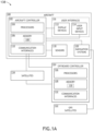
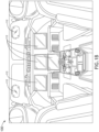
- FIGS. 1A-1B illustrate an aircraft including a system for separating avionics charts into a plurality of display panels, in accordance with one or more embodiments of the present disclosure.
- the aircraft 100 may include an aircraft controller 102 (e.g., on-board/run-time controller).
- the aircraft controller 102 may include one or more processors 104, memory 106 configured to store one or more program instructions 108, and/or one or more communication interfaces 110.
- the aircraft 100 may include an avionics environment such as, but not limited to, a cockpit.
- the aircraft controller 102 may be coupled (e.g., physically, electrically, and/or communicatively) to one or more display devices 112.
- the one or more display devices 112 may be configured to display three-dimensional images and/or two-dimensional images. Referring now to FIG.
- the avionics environment may include any number of display devices 112 (e.g., one, two, three, or more displays) such as, but not limited to, one or more head-down displays (HDDs) 112, one or more head-up displays (HUDs) 112, one or more multi-function displays (MFDs), one or more adaptive flight displays (AFDs) 112, one or more primary flight displays (PFDs) 112, or the like.
- the one or more display devices 112 may be employed to present flight data including, but not limited to, situational awareness data (e.g., chart data) and/or flight queue data to a pilot or other crew member.
- the situational awareness data e.g., chart data
- the situational awareness data may be based on, but is not limited to, aircraft performance parameters, aircraft performance parameter predictions, sensor readings, alerts, or the like.
- the aircraft controller 102 may be coupled (e.g., physically, electrically, and/or communicatively) to one or more user input devices 114.
- the one or more display devices 112 may be coupled to the one or more user input devices 114.
- the one or more display devices 112 may be coupled to the one or more user input devices 114 by a transmission medium that may include wireline and/or wireless portions.
- the one or more display devices 112 may include and/or be configured to interact with one or more user input devices 114.
- the one or more display devices 112 and the one or more user input devices 114 may be standalone components within the aircraft 100. It is noted herein, however, that the one or more display devices 112 and the one or more user input devices 114 may be integrated within one or more common user interfaces 116.
- the aircraft controller 102, one or more offboard controllers 124, and/or the one or more common user interfaces 116 may be standalone components. It is noted herein, however, that the aircraft controller 102, the one or more offboard controllers 124, and/or the one or more common user interfaces 116 may be integrated within one or more common housings or chassis.
- the aircraft controller 102 may be coupled (e.g., physically, electrically, and/or communicatively) to and configured to receive data from one or more aircraft sensors 118.
- the one or more aircraft sensors 118 may be configured to sense a particular condition(s) external or internal to the aircraft 100 and/or within the aircraft 100.
- the one or more aircraft sensors 118 may be configured to output data associated with particular sensed condition(s) to one or more components/systems onboard the aircraft 100.
- the one or more aircraft sensors 118 may include, but are not limited to, one or more inertial measurement units, one or more airspeed sensors, one or more radio altimeters, one or more flight dynamic sensors (e.g., sensors configured to sense pitch, bank, roll, heading, and/or yaw), one or more weather radars, one or more air temperature sensors, one or more surveillance sensors, one or more air pressure sensors, one or more engine sensors, and/or one or more optical sensors (e.g., one or more cameras configured to acquire images in an electromagnetic spectrum range including, but not limited to, the visible light spectrum range, the infrared spectrum range, the ultraviolet spectrum range, or any other spectrum range known in the art).
- flight dynamic sensors e.g., sensors configured to sense pitch, bank, roll, heading, and/or yaw
- weather radars e.g., sensors configured to sense pitch, bank, roll, heading, and/or yaw
- one or more air temperature sensors e.g., sensors configured to sense pitch, bank, roll, heading
- the aircraft controller 102 may be coupled (e.g., physically, electrically, and/or communicatively) to and configured to receive data from one or more navigational systems 120.
- the one or more navigational systems 120 may be coupled (e.g., physically, electrically, and/or communicatively) to and in communication with one or more GPS satellites 122, which may provide vehicular location data (e.g., aircraft location data) to one or more components/systems of the aircraft 100.
- the one or more navigational systems 120 may be implemented as a global navigation satellite system (GNSS) device, and the one or more GPS satellites 122 may be implemented as GNSS satellites.
- the one or more navigational systems 120 may include a GPS receiver and a processor.
- the one or more navigational systems 120 may receive or calculate location data from a sufficient number (e.g., at least four) of GPS satellites 122 in view of the aircraft 100 such that a GPS solution may be calculated.
- the one or more aircraft sensors 118 may operate as a navigation device 120, being configured to sense any of various flight conditions or aircraft conditions typically used by aircraft and output navigation data (e.g., aircraft location data, aircraft orientation data, aircraft direction data, aircraft speed data, and/or aircraft acceleration data).
- the various flight conditions or aircraft conditions may include altitude, aircraft location (e.g., relative to the earth), aircraft orientation (e.g., relative to the earth), aircraft speed, aircraft acceleration, aircraft trajectory, aircraft pitch, aircraft bank, aircraft roll, aircraft yaw, aircraft heading, air temperature, and/or air pressure.
- the one or more aircraft sensors 118 may provide aircraft location data and aircraft orientation data, respectively, to the one or more processors 104, 126.
- the aircraft controller 102 of the aircraft 100 may be coupled (e.g., physically, electrically, and/or communicatively) to one or more offboard controllers 124.
- the one or more offboard controllers 124 may include one or more processors 126, memory 128 configured to store one or more programs instructions 130 and/or one or more communication interfaces 132.
- the aircraft controller 102 and/or the one or more offboard controllers 124 may be coupled (e.g., physically, electrically, and/or communicatively) to one or more satellites 134.
- the aircraft controller 102 and/or the one or more offboard controllers 124 may be coupled (e.g., physically, electrically, and/or communicatively) to one another via the one or more satellites 134.
- at least one component of the aircraft controller 102 may be configured to transmit data to and/or receive data from at least one component of the one or more offboard controllers 124, and vice versa.
- At least one component of the aircraft controller 102 may be configured to record event logs and may transmit the event logs to at least one component of the one or more offboard controllers 124, and vice versa.
- at least one component of the aircraft controller 102 may be configured to receive information and/or commands from the at least one component of the one or more offboard controllers 124, either in response to (or independent of) the transmitted event logs, and vice versa.
- the aircraft 100 and the components onboard the aircraft 100, the one or more offboard controllers 124, the one or more GPS satellites 122, and/or the one or more satellites 134 may be considered components of a system 138, for purposes of the present disclosure.
- the one or more processors 104, 126 may include any one or more processing elements, micro-controllers, circuitry, field programmable gate array (FPGA) or other processing systems, and resident or external memory for storing data, executable code, and other information accessed or generated by the aircraft controller 102 and/or the one or more offboard controllers 124.
- the one or more processors 104, 126 may include any microprocessor device configured to execute algorithms and/or program instructions. It is noted herein, however, that the one or more processors 104, 126 are not limited by the materials from which it is formed or the processing mechanisms employed therein and, as such, may be implemented via semiconductor(s) and/or transistors (e.g., using electronic integrated circuit (IC) components), and so forth.
- IC electronic integrated circuit
- processor may be broadly defined to encompass any device having one or more processing elements, which execute a set of program instructions from a non-transitory memory medium (e.g., the memory), where the set of program instructions is configured to cause the one or more processors to carry out any of one or more process steps.
- a non-transitory memory medium e.g., the memory
- the memory 106, 128 may include any storage medium known in the art suitable for storing the set of program instructions executable by the associated one or more processors.
- the memory 106, 128 may include a non-transitory memory medium.
- the memory 106, 128 may include, but is not limited to, a read-only memory (ROM), a random access memory (RAM), a magnetic or optical memory device (e.g., disk), a magnetic tape, a solid state drive, flash memory (e.g., a secure digital (SD) memory card, a mini-SD memory card, and/or a micro-SD memory card), universal serial bus (USB) memory devices, and the like.
- ROM read-only memory
- RAM random access memory
- magnetic or optical memory device e.g., disk
- magnetic tape e.g., a magnetic tape
- solid state drive e.g., a solid state drive
- flash memory e.g., a secure digital (SD) memory card, a mini-SD memory card
- the memory 106, 128 may be configured to provide display information to the display device (e.g., the one or more display devices 112). In addition, the memory 106, 128 may be configured to store user input information from a user input device of a user interface.
- the memory 106, 128 may be housed in a common controller housing with the one or more processors.
- the memory 106, 128 may, alternatively or in addition, be located remotely with respect to the spatial location of the processors and/or a controller. For instance, the one or more processors and/or the controller may access a remote memory (e.g., server), accessible through a network (e.g., internet, intranet, and the like).
- the aircraft controller 102 and/or the one or more offboard controllers 124 may be configured to perform one or more process steps, as defined by the one or more sets of program instructions 108, 130.
- the one or more process steps may be performed iteratively, concurrently, and/or sequentially.
- the one or more sets of program instructions 108, 130 may be configured to operate via a control algorithm, a neural network (e.g., with states represented as nodes and hidden nodes and transitioning between them until an output is reached via branch metrics), a kernel-based classification method, a Support Vector Machine (SVM) approach, canonical-correlation analysis (CCA), factor analysis, flexible discriminant analysis (FDA), principal component analysis (PCA), multidimensional scaling (MDS), principal component regression (PCR), projection pursuit, data mining, prediction-making, exploratory data analysis, supervised learning analysis, boolean logic (e.g., resulting in an output of a complete truth or complete false value), fuzzy logic (e.g., resulting in an output of one or more partial truth values instead of a complete truth or complete false value), or the like.
- a neural network e.g., with states represented as nodes and hidden nodes and transitioning between them until an output is reached via branch metrics
- SVM Support Vector Machine
- CCA canonical-correlation analysis
- the one or more sets of program instructions 108, 130 may be configured to operate via proportional control, feedback control, feedforward control, integral control, proportional-derivative (PD) control, proportional-integral (PI) control, proportional-integral-derivative (PID) control, or the like.
- proportional control feedback control, feedforward control, integral control, proportional-derivative (PD) control, proportional-integral (PI) control, proportional-integral-derivative (PID) control, or the like.
- the one or more communication interfaces 110, 134 may be operatively configured to communicate with one or more components of the aircraft controller 102 and/or the one or more offboard controllers 124.
- the one or more communication interfaces 110, 134 may also be coupled (e.g., physically, electrically, and/or communicatively) with the one or more processors 104, 126 to facilitate data transfer between components of the one or more components of the aircraft controller 102 and/or the one or more offboard controllers 124 and the one or more processors 104, 126.
- the one or more communication interfaces 110, 134 may be configured to retrieve data from the one or more processors 104, 126, or other devices, transmit data for storage in the memory 106, 128, retrieve data from storage in the memory 106, 128, or the like.
- the aircraft controller 102 and/or the one or more offboard controllers 124 may be configured to receive and/or acquire data or information from other systems or tools by a transmission medium that may include wireline and/or wireless portions.
- the aircraft controller 102 and/or the one or more offboard controllers 124 may be configured to transmit data or information (e.g., the output of one or more procedures of the inventive concepts disclosed herein) to one or more systems or tools by a transmission medium that may include wireline and/or wireless portions (e.g., a transmitter, receiver, transceiver, physical connection interface, or any combination).
- the transmission medium may serve as a data link between the aircraft controller 102 and/or the one or more offboard controllers 124 and the other subsystems (e.g., of the aircraft 100 and/or the system 138).
- the aircraft controller 102 and/or the one or more offboard controllers 124 may be configured to send data to external systems via a transmission medium (e.g., network connection).
- the one or more display devices 112 may include any display device known in the art.
- the display devices 112 may include, but are not limited to, one or more head-down displays (HDDs), one or more HUDs, one or more multi-function displays (MFDs), or the like.
- the display devices 112 may include, but are not limited to, a liquid crystal display (LCD), a light-emitting diode (LED) based display, an organic light-emitting diode (OLED) based display, an electroluminescent display (ELD), an electronic paper (E-ink) display, a plasma display panel (PDP), a display light processing (DLP) display, or the like.
- LCD liquid crystal display
- LED light-emitting diode
- OLED organic light-emitting diode
- ELD electroluminescent display
- E-ink electronic paper
- PDP plasma display panel
- DLP display light processing
- any display device capable of integration with the user input device e.g., touchscreen, bezel mounted interface, keyboard, mouse, trackpad, and the like is suitable for implementation in the present invention.
- the one or more user input devices 114 may include any user input device known in the art.
- the user input device 114 may include, but is not limited to, a keyboard, a keypad, a touchscreen, a lever, a knob, a scroll wheel, a track ball, a switch, a dial, a sliding bar, a scroll bar, a slide, a handle, a touch pad, a paddle, a steering wheel, a joystick, a bezel input device, or the like.
- a touchscreen interface those skilled in the art should recognize that a large number of touchscreen interfaces may be suitable for implementation in the present invention.
- the display device may be integrated with a touchscreen interface, such as, but not limited to, a capacitive touchscreen, a resistive touchscreen, a surface acoustic based touchscreen, an infrared based touchscreen, or the like.
- a touchscreen interface such as, but not limited to, a capacitive touchscreen, a resistive touchscreen, a surface acoustic based touchscreen, an infrared based touchscreen, or the like.
- any touchscreen interface capable of integration with the display portion of a display device is suitable for implementation in the present invention.
- the user input device may include, but is not limited to, a bezel mounted interface.
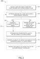
- FIG. 2 illustrates a flowchart depicting a method or process 200 for separating large avionics charts into multiple display panels, in accordance with one or more embodiments of the disclosure.
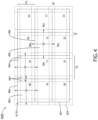
- FIGS. 4-5 generally illustrate graphical representations of a plurality of display panels of a separated avionics chart, in accordance with one or more embodiments of the disclosure.
- chart data may be received from a third-party chart provider.
- the offboard controller 124 may be configured to receive chart data from a third-party chart provider.
- the offboard controller 124 may be configured to receive enroute chart data from a third-party enroute chart provider.
- the offboard controller 124 may be configured to receive terminal chart data from a third-party terminal chart provider.
- offboard controller 124 may be configured to receive any type of chart known from any suitable third-party chart provider.
- a step 204 it is determined whether the received chart data exceeds a predetermined threshold.
- the offboard controller 124 may be configured to compare a size of the received chart data to a predetermined threshold to determine whether the received chart data exceeds the predetermined threshold.
- the offboard controller 124 may be configured to compare a data size of the received chart data to a predetermined chart data size threshold to determine whether the received chart data exceeds the predetermined chart data size threshold (e.g., whether the received chart data is too large in data size).
- the predetermined chart data size threshold may be any threshold suitable for the display system.
- the predetermined chart data size threshold may be between 1.2 - 1.5 Mb.
- the predetermined chart data size threshold may be 1.3 Mb.
- the chart data may be provided to the on-board aircraft controller 102 for display on the one or more display devices 112.
- the chart is not separated into a plurality of display panels prior to display on the one or more display devices 112.
- a plurality of display panels 402 may be generated. It is noted that the display panels may be labeled using any labeling mechanism suitable for defining each individual display panel.
- the labels e.g., 00, 01, 02, ...) shown in FIG. 4 are provided merely for illustrative purposes and shall not be construed as limiting the scope of the present disclosure.
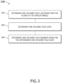
- FIG. 3 illustrates a flowchart depicting a method or process 208 for generating the plurality of display panels, in accordance with one or more embodiments of the disclosure.
- one or more fold locations may be determined.
- the offboard controller 124 may be configured to generate a plurality of display panels 402 by determining one or more fold locations.
- the offboard controller 124 may be configured to adjust one or more dimensions of the received chart image and determine a size of the adjusted image.
- the offboard controller 124 may be configured to remove one or more portions of the received chart image (e.g., title page, legend, or the like) to generate an adjusted image and determine a size of the adjusted image.
- one or more fold sizes may be determined.
- the offboard controller 124 may be configured to determine an x-axis fold size (F x ) and further configured to determine a y-axis fold size (F y ).
- the offboard controller 124 may be configured to adjust the size of the adjusted image based on a folding algorithm.
- the adjusted image may be divided by a predetermined fold size threshold (e.g., divided by 10 inches) to generate one or more pages (P) and a remainder (R). If the remainder (R) is less than a predetermined threshold, then the offboard controller 124 may be configured to distribute that amount to each page (P). At that point, each page may have a size of S + R P .
- S may be 10
- P may be 5
- R may be 2 for a 52-inch wide chart, such that the panel size may be 10.4 inches (10 + 2/5). If the remainder (R) is more than 4, then the offboard controller 124 may be configured to add another page (P). For example, for a 57-inche wide chart, the chart may have five (5) panels of 10 inches and one (1) of 7 inches. It is noted that the aforementioned process may be performed for both the x- (horizontal) and y-axis (vertical).
- the fold size may be configurable.
- the offboard controller 124 may be configured to determine a fold size based on the dimensions of the chart legend 320. For instance, where a panel includes data that exceeds a predetermined threshold, the offboard controller 124 may be configured to adjust the size of the panel to generate an adjusted panel 502 that is smaller than the original panel 402.
- FIG. 5 depicts only the panels 402, 502 of the chart 400. It is noted that FIG. 5 is provided merely for illustrative purposes and shall not be construed as limiting the scope of the present disclosure.
- the offboard controller 124 may be configured to assign a fold number (Fn y below, Fn x below) based on the F x and F y values.
- a fold number Fn y below, Fn x below
- the first value e.g., Fn y below value
- the second value e.g., Fn y below value
- the y-value is given first because it facilitates that left-to-right reading of the numbers and many charts do not have horizontal folds.
- the offboard controller 124 may be configured to place each graphical object of the received chart into one or more sections (SS) by comparing the X and Y coordinates to Section Begin and End coordinates (e.g., SB X/Y and SE X/Y ). It is noted that objects may be placed in more than one section. The new coordinates of each object may then be determined. Given the fold number and the .svg X/Y position, the new X and Y positions follow.
- the offboard controller 124 may be configured to assign the left panel in each row an X index of zero, increasing by one across the row, as illustrated by Equation 1 (e.g., Fnx).
- the offboard controller 124 may be configured to assign the top panel in each column a Y index of 0, increasing by one down each column, as illustrated by Equation 3 (e.g., Fny). It is noted that together, Fny and Fnx make up the labels/cell numbers shown in FIG. 4 (e.g., 00,01,... 23).
- the offboard controller 124 may be configured to receive data with positions based on the entire chart.
- the original position (X) may need to have a new position calculated (using Equation 2) because the panels are displayed independently.
- X may be 35
- Fnx is 3
- Fx is 10
- B is 1, such that the new calculated X coordinate is 6.
- one or more buffer lengths may be determined.
- the offboard controller 124 may be configured to determine one or more buffer lengths (B) 404.
- the offboard controller 124 may be configured to determine a buffer length 404 and add such buffer length 404 to each side of the display panel 402 to form a section 406.
- the term "buffer length” and variants thereof may be defined as an amount added to the virtual fold so that there is some overlap between adjacent display panels.
- the term "section” and variants thereof may be defined as the display panel (e.g., displayed image of the fold) plus the buffer. It is noted that the section is what the offboard controller 124 products and stores as a displayable entity.
- the buffer length 404 may be any buffer length.
- the buffer length 404 may be 1.00 inches.
- a first display panel 402 may include a first buffer length 404 added to a first side of the display panel (e.g., left side of the display panel 00), a second buffer length 404 added to a second side of the display panel (e.g., top side of the display panel 00), a third buffer length 404 added to a third side of the display panel (e.g., right side of the display panel 00), and a fourth buffer length 404 added to a fourth side of the display panel (e.g., bottom side of the display panel 00), where the first display panel 402 (e.g., display panel 00) and the four buffer lengths 404 may form a first section 406.
- a second display panel 402 may include a first buffer length 404 added to a first side of the display panel (e.g., left side of the display panel 01), a second buffer length 404 added to a second side of the display panel (e.g., top side of the display panel 01), a third buffer length 404 added to a third side of the display panel (e.g., right side of the display panel 01), and a fourth buffer length 404 added to a fourth side of the display panel (e.g., bottom side of the display panel 01), where the second display panel 402 (e.g., display panel 01) and the four buffer lengths 404 may form a second section 406.
- a buffer length 404 is added around the perimeter of the display panels 402 (e.g., display panel 00 and display panel 01), such that there is some overlap between the adjacent sections 00, 01, respectively.
- a user viewing display panel 00 may pan through the right buffer of the first panel 00 and the left buffer of the second panel 01, such that any chart data on either side of the fold line may be easily viewed.
- one or more pre-processing chart image steps may be performed.
- the offboard controller 124 may be configured to determine whether any part of the symbol (e.g., arrowhead, or the like) is in a section. If any part of the symbol is in a section then the offboard controller 124 may be configured to add a whole symbol. Further, the offboard controller 124 may be configured to apply a clipping region to restrict the symbol to a visual boundary.
- the offboard controller 124 may be configured determine whether there is an embedded Clip Path for each group. If there is an embedded clip path then the offboard controller 124 may be configured to process the full related Path and convert to a set of clipped lines or a clipped shape. Further, the offboard controller 124 may be configured to process the full related path and convert the set of clipped lines (or clipped shape).
- the offboard controller 124 may be configured to allocate the clipped lines or clipped shapes.
- the offboard controller 124 may be configured to step through the Path, each line and arc command within the path comparing it to each set of section boundaries. If the start and end points of each line are within a section boundary, the offboard controller 124 may be configured to add the line command to the appropriate section(s). If the start and end points of each arc are within a section boundary, the offboard controller 124 may be configured add the arc to the appropriate section(s). If the radius and center of an arc would place part of it within a section boundary, the offboard controller 124 may be configured to add the arc to the appropriate section(s). It is noted that very long arcs can be broken at section boundaries if desired.
- the offboard controller 124 may be configured to clip the line at the section boundary (to remove very long lines from being drawn, if necessary). If the end point of a line or arc is outside a section, the offboard controller 124 may be configured to track the absolute coordinates in case the lines within the path re-enter the section.
- the offboard controller 124 may be configured to step through the Path. If the entire path is within a section, the offboard controller 124 may be configured to output the path. If the path enters or exits a section, the offboard controller 124 may be configured to mark the point on the section boundary. The offboard controller 124 may be configured to mark all entries and exits along a boundary. It is noted that these points are sorted and then connected with straight lines along the boundary to complete the shape within each section. Further, it is noted that sorting may be by y value when the break occurs along an x border and by x value when the break occurs along a y border.
- the offboard controller 124 may be configured to track the absolute coordinates to determine where the path re-enters the section. It is noted that the completed path may be unchanged or may be multiple paths separated across multiple sections.
- a plurality of output files are generated based on the separated plurality of display panels 402.
- the offboard controller 124 may be configured to generate a plurality of output files including section data.
- the plurality of output files may be an SVG file.
- the generated output files may be provided to the aircraft controller 102 for display on the one or more display panels 112.
- the generated output files from the offboard controller 124 may be provided to the aircraft controller 102 via the communication interfaces 110, 134.
- step 218 prior to providing the plurality of output files to the on-board aircraft controller 102 (step 216), it is determined whether the chart data of the generated output files exceeds a predetermined threshold. If the chart data of the generated output file exceeds the predetermined threshold (as discussed previously herein), then the offboard controller 124 may be configured to break up at least a portion of the previously separated chart (using steps 208-216) such that the aircraft controller 102 may have ample storage to store/run the output file when displaying the chart.
- the offboard controller 124 may be configured to break up the display panel 11 into two additional display panels 502.
- each display panel 502 may be stored individually as its own separate chart, rather than stored as a single display panel.
Landscapes
- Engineering & Computer Science (AREA)
- Physics & Mathematics (AREA)
- General Physics & Mathematics (AREA)
- Aviation & Aerospace Engineering (AREA)
- Theoretical Computer Science (AREA)
- Computer Hardware Design (AREA)
- Human Computer Interaction (AREA)
- General Engineering & Computer Science (AREA)
- Control Of Indicators Other Than Cathode Ray Tubes (AREA)
- Controls And Circuits For Display Device (AREA)
Abstract

Description
- Avionics display systems often do not have ample data storage space available to store avionics chart data. There is a need for a system and method for lowering the individual chart data size.
- A method for separating avionics charts into a plurality of display panels is disclosed, in accordance with one or more embodiments of the present disclosure. The method includes receiving chart data for a virtual avionics chart. The method includes determining whether the received chart data exceeds a predetermined threshold. The method includes generating a plurality of display panels if the received chart data exceeds the predetermined threshold. The method includes determining one or more buffer lengths for the generated plurality of display panels. The method includes generating a plurality of output files based on the generated plurality of display panels and the determined one or more buffer lengths.
- In some embodiments, the method may include providing the plurality of output files to an on-board aircraft controller for display on one or more display devices of an aircraft.
- In some embodiments, the determine whether the received chart data exceeds a predetermined threshold may include comparing a data size of the received chart data to a predetermined data size threshold.
- In some embodiments, the predetermined data size threshold may be between 1.2 Mb and 1.5 Mb.
- In some embodiments, the predetermined data size threshold may be 1.3 Mb.
- In some embodiments, the generate a plurality of display panels if the received chart data exceeds the predetermined threshold may further include determining one or more fold locations; determining one or more fold sizes; and assigning one or more fold numbers to one or more sections based on at least one of one or more x-values or one or more y-values.
- In some embodiments, the one or more buffer lengths may be 1.00 inches.
- In some embodiments, the method may further include determining whether chart data of the generated plurality of output files exceeds a predetermined threshold and adjusting a fold size of the one or more display panels if the chart data of the generated plurality of output files for the one or more display panels exceeds the predetermined threshold.
- A system for separating avionics charts into a plurality of display panels is disclosed, in accordance with one or more embodiments of the present disclosure. The system includes one or more controllers including one or more processors configured to execute a set of program instructions stored in a memory, the set of program instructions configured to cause the one or more processors to: receive chart data for a virtual avionics chart; determine whether the received chart data exceeds a predetermined threshold; generate a plurality of display panels if the received chart data exceeds the predetermined threshold; determine one or more buffer lengths for the generated plurality of display panels; and generate a plurality of output files based on the generated plurality of display panels and the determined one or more buffer lengths.
- In some embodiments, the one or more controllers may be configured to provide the plurality of output files to an on-board aircraft controller for display on one or more display devices of an aircraft.
- In some embodiments, the determine whether the received chart data exceeds a predetermined threshold may include comparing a data size of the received chart data to a predetermined data size threshold.
- In some embodiments, the predetermined data size threshold may be between 1.2 Mb and 1.5 Mb.
- In some embodiments, the predetermined data size threshold may be 1.3 Mb.
- In some embodiments, the generate a plurality of display panels if the received chart data exceeds the predetermined threshold may further include determining one or more fold locations; determining one or more fold sizes; and assigning one or more fold numbers to one or more sections based on at least one of one or more x-values or one or more y-values.
- In some embodiments, the method may further include determining whether chart data of the generated plurality of output files exceeds a predetermined threshold and adjusting a fold size of the one or more display panels if the chart data of the generated plurality of output files for the one or more display panels exceeds the predetermined threshold.
- This Summary is provided solely as an introduction to subject matter that is fully described in the Detailed Description and Drawings. The Summary should not be considered to describe essential features nor be used to determine the scope of the Claims. Moreover, it is to be understood that both the foregoing Summary and the following Detailed Description are examples and explanatory only and are not necessarily restrictive of the subject matter claimed.
- The detailed description is described with reference to the accompanying figures. The use of the same reference numbers in different instances in the description and the figures may indicate similar or identical items. Various embodiments or examples ("examples") of the present disclosure are disclosed in the following detailed description and the accompanying drawings. The drawings are not necessarily to scale. In general, operations of disclosed processes may be performed in an arbitrary order, unless otherwise provided in the claims. In the drawings:
-
FIG. 1A illustrates a simplified block diagram of an aircraft including the system for separating avionics charts into a plurality of display panels, in accordance with one or more embodiments of the present disclosure; -
FIG. 1B illustrates an aircraft including the system for separating avionics charts into a plurality of display panels, in accordance with one or more embodiments of the present disclosure; -
FIG. 2 illustrates a flowchart depicting a method or process for separating avionics charts into a plurality of display panels, in accordance with one or more embodiments of the present disclosure; -
FIG. 3 illustrates a flowchart depicting a method or process for separating avionics charts into a plurality of display panels, in accordance with one or more embodiments of the present disclosure; -
FIG. 4 illustrates a simplified schematic of an avionic chart separated into a plurality of display panels, in accordance with one or more embodiments of the present disclosure; -
FIG. 5 illustrates a simplified schematic of an avionic chart separated into a plurality of display panels, in accordance with one or more embodiments of the present disclosure. - Reference will now be made in detail to the subject matter disclosed, which is illustrated in the accompanying drawings.
- Before explaining one or more embodiments of the present disclosure in detail, it is to be understood the embodiments are not limited in their application to the details of construction and the arrangement of the components or steps or methodologies set forth in the following description or illustrated in the drawings. In the following detailed description of embodiments, numerous specific details may be set forth in order to provide a more thorough understanding of the present disclosure. However, it will be apparent to one of ordinary skill in the art having the benefit of the instant disclosure the embodiments disclosed herein may be practiced without some of these specific details. In other instances, well-known features may not be described in detail to avoid unnecessarily complicating the instant disclosure.
- As used herein a letter following a reference numeral is intended to reference an embodiment of the feature or element that may be similar, but not necessarily identical, to a previously described element or feature bearing the same reference numeral (e.g., 1, 1a, 1b). Such shorthand notations are used for purposes of convenience only and should not be construed to limit the disclosure in any way unless expressly stated to the contrary.
- Further, unless expressly stated to the contrary, "or" refers to an inclusive or and not to an exclusive or. For example, a condition A or B is satisfied by any one of the following: A is true (or present) and B is false (or not present), A is false (or not present) and B is true (or present), and both A and B are true (or present).
- In addition, use of "a" or "an" may be employed to describe elements and components of embodiments disclosed herein. This is done merely for convenience and "a" and "an" are intended to include "one" or "at least one," and the singular also includes the plural unless it is obvious that it is meant otherwise.
- Finally, as used herein any reference to "one embodiment" or "some embodiments" means that a particular element, feature, structure, or characteristic described in connection with the embodiment is included in at least one embodiment disclosed herein. The appearances of the phrase "in some embodiments" in various places in the specification are not necessarily all referring to the same embodiment, and embodiments may include one or more of the features expressly described or inherently present herein, or any combination of or sub-combination of two or more such features, along with any other features which may not necessarily be expressly described or inherently present in the instant disclosure.
-
FIGS. 1A-5 generally illustrate a system and method for separating avionics charts into a plurality of display panels, in accordance with one or more embodiments of the present disclosure. - Aeronautical charts (or avionics charts) are widely used for air navigation. The Federal Aviation Administration (FAA) publishes charts for each stage of Visual Flight Rules (VFR) and Instrument Flight Rules (IFR) air navigation including training, planning, and departures, enroute (for low and high altitudes), approaches, and taxiing charts. These charts are frequently updated by the FAA. For example, the charts may be updated about once a month. As such, a pilot must ensure that they have the most-up-to-date charts on-board when flying.
- In general, enroute charts provide aeronautical information for enroute instrument navigation. High altitude enroute charts are used to provide information for navigation at or above 18,000 ft MSL, while low altitude enroute charts are used to below information for navigation below 18,000 ft MSL. For example, high altitude enroute charts include jet and RNAV routes, identification and frequency of radio aids, selected airports, distances, time zones, special use air space, and the like. By way of another example, low altitude enroute charts include information regarding airports, NAVAIDs, communications, air traffic services, airspace, and the like. In general, these enroute charts are large in both physical size and chart data size.
- Avionics display systems often do not have ample data storage space available on the display hardware to store the data for each aeronautical chart. For example, there may about approximately 1.3 Mb of available space in the display hardware (which is the upper limit that can be displayed at one time) and a given chart may be greater than 1.3 Mb (e.g., 25 Mb). Therefore, there is a need for a system and method for lowering the individual chart size, such that the system is able to display the chart.
- As such, it would be desirable to provide a system and method for separating large avionics charts into multiple display panels. The system and method should allow charts to be processed off-line, such that the avionic resources have the bandwidth to display the processed charts during run-time. For example, the system and method may be configured to systematically break up the avionics charts into a plurality of panels to display on multiple display panels. By way of another example, the system and method may be configured to allow for overlapping panels to minimize panel swapping along the edges. By way of another example, the system and method may be configured to allow for program variance in choosing panel and buffer sizes. By way of another example, the system and method may be configured to modify the coordinates of the chart display items to new locations based on the panel boundaries (e.g., items outside the defined section are discarded, items that span sections are modified, and the like). By way of another example, the system and method may be configured to modify clip structures to the new boundaries (e.g., items outside the defined section are discarded, items that span sections are modified, or the like). By way of another example, the system and method may be configured to create new structures based on new boundaries by reassembling the modified lines and clip structures, such that each panel may be processed as an individual chart.
-
FIGS. 1A-1B illustrate an aircraft including a system for separating avionics charts into a plurality of display panels, in accordance with one or more embodiments of the present disclosure. - Referring now to
FIG. 1A , theaircraft 100 may include an aircraft controller 102 (e.g., on-board/run-time controller). Theaircraft controller 102 may include one ormore processors 104,memory 106 configured to store one ormore program instructions 108, and/or one or more communication interfaces 110. - The
aircraft 100 may include an avionics environment such as, but not limited to, a cockpit. Theaircraft controller 102 may be coupled (e.g., physically, electrically, and/or communicatively) to one ormore display devices 112. The one ormore display devices 112 may be configured to display three-dimensional images and/or two-dimensional images. Referring now toFIG. 1B , the avionics environment (e.g., the cockpit) may include any number of display devices 112 (e.g., one, two, three, or more displays) such as, but not limited to, one or more head-down displays (HDDs) 112, one or more head-up displays (HUDs) 112, one or more multi-function displays (MFDs), one or more adaptive flight displays (AFDs) 112, one or more primary flight displays (PFDs) 112, or the like. The one ormore display devices 112 may be employed to present flight data including, but not limited to, situational awareness data (e.g., chart data) and/or flight queue data to a pilot or other crew member. For example, the situational awareness data (e.g., chart data) may be based on, but is not limited to, aircraft performance parameters, aircraft performance parameter predictions, sensor readings, alerts, or the like. - Referring again to
FIG. 1A , theaircraft controller 102 may be coupled (e.g., physically, electrically, and/or communicatively) to one or moreuser input devices 114. The one ormore display devices 112 may be coupled to the one or moreuser input devices 114. For example, the one ormore display devices 112 may be coupled to the one or moreuser input devices 114 by a transmission medium that may include wireline and/or wireless portions. The one ormore display devices 112 may include and/or be configured to interact with one or moreuser input devices 114. - The one or
more display devices 112 and the one or moreuser input devices 114 may be standalone components within theaircraft 100. It is noted herein, however, that the one ormore display devices 112 and the one or moreuser input devices 114 may be integrated within one or morecommon user interfaces 116. - Where the one or
more display devices 112 and the one or moreuser input devices 114 are housed within the one or morecommon user interfaces 116, theaircraft controller 102, one or moreoffboard controllers 124, and/or the one or morecommon user interfaces 116 may be standalone components. It is noted herein, however, that theaircraft controller 102, the one or moreoffboard controllers 124, and/or the one or morecommon user interfaces 116 may be integrated within one or more common housings or chassis. - The
aircraft controller 102 may be coupled (e.g., physically, electrically, and/or communicatively) to and configured to receive data from one ormore aircraft sensors 118. The one ormore aircraft sensors 118 may be configured to sense a particular condition(s) external or internal to theaircraft 100 and/or within theaircraft 100. The one ormore aircraft sensors 118 may be configured to output data associated with particular sensed condition(s) to one or more components/systems onboard theaircraft 100. Generally, the one ormore aircraft sensors 118 may include, but are not limited to, one or more inertial measurement units, one or more airspeed sensors, one or more radio altimeters, one or more flight dynamic sensors (e.g., sensors configured to sense pitch, bank, roll, heading, and/or yaw), one or more weather radars, one or more air temperature sensors, one or more surveillance sensors, one or more air pressure sensors, one or more engine sensors, and/or one or more optical sensors (e.g., one or more cameras configured to acquire images in an electromagnetic spectrum range including, but not limited to, the visible light spectrum range, the infrared spectrum range, the ultraviolet spectrum range, or any other spectrum range known in the art). - The
aircraft controller 102 may be coupled (e.g., physically, electrically, and/or communicatively) to and configured to receive data from one or morenavigational systems 120. The one or morenavigational systems 120 may be coupled (e.g., physically, electrically, and/or communicatively) to and in communication with one ormore GPS satellites 122, which may provide vehicular location data (e.g., aircraft location data) to one or more components/systems of theaircraft 100. For example, the one or morenavigational systems 120 may be implemented as a global navigation satellite system (GNSS) device, and the one ormore GPS satellites 122 may be implemented as GNSS satellites. The one or morenavigational systems 120 may include a GPS receiver and a processor. For example, the one or morenavigational systems 120 may receive or calculate location data from a sufficient number (e.g., at least four) ofGPS satellites 122 in view of theaircraft 100 such that a GPS solution may be calculated. - It is noted herein the one or
more aircraft sensors 118 may operate as anavigation device 120, being configured to sense any of various flight conditions or aircraft conditions typically used by aircraft and output navigation data (e.g., aircraft location data, aircraft orientation data, aircraft direction data, aircraft speed data, and/or aircraft acceleration data). For example, the various flight conditions or aircraft conditions may include altitude, aircraft location (e.g., relative to the earth), aircraft orientation (e.g., relative to the earth), aircraft speed, aircraft acceleration, aircraft trajectory, aircraft pitch, aircraft bank, aircraft roll, aircraft yaw, aircraft heading, air temperature, and/or air pressure. By way of another example, the one ormore aircraft sensors 118 may provide aircraft location data and aircraft orientation data, respectively, to the one ormore processors - The
aircraft controller 102 of theaircraft 100 may be coupled (e.g., physically, electrically, and/or communicatively) to one or moreoffboard controllers 124. - The one or more
offboard controllers 124 may include one ormore processors 126,memory 128 configured to store one ormore programs instructions 130 and/or one or more communication interfaces 132. - The
aircraft controller 102 and/or the one or moreoffboard controllers 124 may be coupled (e.g., physically, electrically, and/or communicatively) to one ormore satellites 134. For example, theaircraft controller 102 and/or the one or moreoffboard controllers 124 may be coupled (e.g., physically, electrically, and/or communicatively) to one another via the one ormore satellites 134. For instance, at least one component of theaircraft controller 102 may be configured to transmit data to and/or receive data from at least one component of the one or moreoffboard controllers 124, and vice versa. By way of another example, at least one component of theaircraft controller 102 may be configured to record event logs and may transmit the event logs to at least one component of the one or moreoffboard controllers 124, and vice versa. By way of another example, at least one component of theaircraft controller 102 may be configured to receive information and/or commands from the at least one component of the one or moreoffboard controllers 124, either in response to (or independent of) the transmitted event logs, and vice versa. - It is noted herein that the
aircraft 100 and the components onboard theaircraft 100, the one or moreoffboard controllers 124, the one ormore GPS satellites 122, and/or the one ormore satellites 134 may be considered components of asystem 138, for purposes of the present disclosure. - The one or
more processors aircraft controller 102 and/or the one or moreoffboard controllers 124. In this sense, the one ormore processors more processors - The
memory memory memory memory memory memory memory - The
aircraft controller 102 and/or the one or moreoffboard controllers 124 may be configured to perform one or more process steps, as defined by the one or more sets ofprogram instructions program instructions program instructions - The one or
more communication interfaces aircraft controller 102 and/or the one or moreoffboard controllers 124. For example, the one ormore communication interfaces more processors aircraft controller 102 and/or the one or moreoffboard controllers 124 and the one ormore processors more communication interfaces more processors memory memory aircraft controller 102 and/or the one or moreoffboard controllers 124 may be configured to receive and/or acquire data or information from other systems or tools by a transmission medium that may include wireline and/or wireless portions. By way of another example, theaircraft controller 102 and/or the one or moreoffboard controllers 124 may be configured to transmit data or information (e.g., the output of one or more procedures of the inventive concepts disclosed herein) to one or more systems or tools by a transmission medium that may include wireline and/or wireless portions (e.g., a transmitter, receiver, transceiver, physical connection interface, or any combination). In this regard, the transmission medium may serve as a data link between theaircraft controller 102 and/or the one or moreoffboard controllers 124 and the other subsystems (e.g., of theaircraft 100 and/or the system 138). In addition, theaircraft controller 102 and/or the one or moreoffboard controllers 124 may be configured to send data to external systems via a transmission medium (e.g., network connection). - The one or
more display devices 112 may include any display device known in the art. For example, thedisplay devices 112 may include, but are not limited to, one or more head-down displays (HDDs), one or more HUDs, one or more multi-function displays (MFDs), or the like. For instance, thedisplay devices 112 may include, but are not limited to, a liquid crystal display (LCD), a light-emitting diode (LED) based display, an organic light-emitting diode (OLED) based display, an electroluminescent display (ELD), an electronic paper (E-ink) display, a plasma display panel (PDP), a display light processing (DLP) display, or the like. Those skilled in the art should recognize that a variety of display devices may be suitable for implementation in the present invention and the particular choice of display device may depend on a variety of factors, including, but not limited to, form factor, cost, and the like. In a general sense, any display device capable of integration with the user input device (e.g., touchscreen, bezel mounted interface, keyboard, mouse, trackpad, and the like) is suitable for implementation in the present invention. - The one or more
user input devices 114 may include any user input device known in the art. For example, theuser input device 114 may include, but is not limited to, a keyboard, a keypad, a touchscreen, a lever, a knob, a scroll wheel, a track ball, a switch, a dial, a sliding bar, a scroll bar, a slide, a handle, a touch pad, a paddle, a steering wheel, a joystick, a bezel input device, or the like. In the case of a touchscreen interface, those skilled in the art should recognize that a large number of touchscreen interfaces may be suitable for implementation in the present invention. For instance, the display device may be integrated with a touchscreen interface, such as, but not limited to, a capacitive touchscreen, a resistive touchscreen, a surface acoustic based touchscreen, an infrared based touchscreen, or the like. In a general sense, any touchscreen interface capable of integration with the display portion of a display device is suitable for implementation in the present invention. In another embodiment, the user input device may include, but is not limited to, a bezel mounted interface. -
FIG. 2 illustrates a flowchart depicting a method orprocess 200 for separating large avionics charts into multiple display panels, in accordance with one or more embodiments of the disclosure.FIGS. 4-5 generally illustrate graphical representations of a plurality of display panels of a separated avionics chart, in accordance with one or more embodiments of the disclosure. - In a
step 202, chart data may be received from a third-party chart provider. For example, theoffboard controller 124 may be configured to receive chart data from a third-party chart provider. In one instance, theoffboard controller 124 may be configured to receive enroute chart data from a third-party enroute chart provider. In another instance, theoffboard controller 124 may be configured to receive terminal chart data from a third-party terminal chart provider. - It is noted that the
offboard controller 124 may be configured to receive any type of chart known from any suitable third-party chart provider. - In a
step 204, it is determined whether the received chart data exceeds a predetermined threshold. For example, theoffboard controller 124 may be configured to compare a size of the received chart data to a predetermined threshold to determine whether the received chart data exceeds the predetermined threshold. In one instance, theoffboard controller 124 may be configured to compare a data size of the received chart data to a predetermined chart data size threshold to determine whether the received chart data exceeds the predetermined chart data size threshold (e.g., whether the received chart data is too large in data size). It is noted that the predetermined chart data size threshold may be any threshold suitable for the display system. For example, the predetermined chart data size threshold may be between 1.2 - 1.5 Mb. For instance, the predetermined chart data size threshold may be 1.3 Mb. - If the received chart data size does not exceed the predetermined threshold (i.e., the data size is less than that predetermined threshold), then in a
step 206, the chart data may be provided to the on-board aircraft controller 102 for display on the one ormore display devices 112. In this regard, the chart is not separated into a plurality of display panels prior to display on the one ormore display devices 112. - If the received chart data size exceeds the predetermined threshold (i.e., the data size is greater than that predetermined threshold), then in a
step 208, a plurality ofdisplay panels 402 may be generated. It is noted that the display panels may be labeled using any labeling mechanism suitable for defining each individual display panel. The labels (e.g., 00, 01, 02, ...) shown inFIG. 4 are provided merely for illustrative purposes and shall not be construed as limiting the scope of the present disclosure. -
FIG. 3 illustrates a flowchart depicting a method orprocess 208 for generating the plurality of display panels, in accordance with one or more embodiments of the disclosure. - In a
step 302, one or more fold locations may be determined. For example, theoffboard controller 124 may be configured to generate a plurality ofdisplay panels 402 by determining one or more fold locations. For instance, theoffboard controller 124 may be configured to adjust one or more dimensions of the received chart image and determine a size of the adjusted image. In this regard, theoffboard controller 124 may be configured to remove one or more portions of the received chart image (e.g., title page, legend, or the like) to generate an adjusted image and determine a size of the adjusted image. - In a
step 304, one or more fold sizes may be determined. For example, theoffboard controller 124 may be configured to determine an x-axis fold size (Fx) and further configured to determine a y-axis fold size (Fy). For instance, theoffboard controller 124 may be configured to adjust the size of the adjusted image based on a folding algorithm. In this regard, the adjusted image may be divided by a predetermined fold size threshold (e.g., divided by 10 inches) to generate one or more pages (P) and a remainder (R). If the remainder (R) is less than a predetermined threshold, then theoffboard controller 124 may be configured to distribute that amount to each page (P). At that point, each page may have a size of
offboard controller 124 may be configured to add another page (P). For example, for a 57-inche wide chart, the chart may have five (5) panels of 10 inches and one (1) of 7 inches. It is noted that the aforementioned process may be performed for both the x- (horizontal) and y-axis (vertical). - Referring to
FIG. 5 , the fold size may be configurable. For example, where the virtual avionics chart includes achart legend 320, theoffboard controller 124 may be configured to determine a fold size based on the dimensions of thechart legend 320. For instance, where a panel includes data that exceeds a predetermined threshold, theoffboard controller 124 may be configured to adjust the size of the panel to generate an adjustedpanel 502 that is smaller than theoriginal panel 402. For purposes of simplicity,FIG. 5 depicts only thepanels chart 400. It is noted thatFIG. 5 is provided merely for illustrative purposes and shall not be construed as limiting the scope of the present disclosure. - In a
step 306, theoffboard controller 124 may be configured to assign a fold number (Fny below, Fnx below) based on the Fx and Fy values. For instance, the first value (e.g., Fny below value) may represent the fold number down and the second value (e.g., Fny below value) may represent the fold number across. It is noted that the y-value is given first because it facilitates that left-to-right reading of the numbers and many charts do not have horizontal folds. - Referring to
FIG. 4 , theoffboard controller 124 may be configured to place each graphical object of the received chart into one or more sections (SS) by comparing the X and Y coordinates to Section Begin and End coordinates (e.g., SBX/Y and SEX/Y). It is noted that objects may be placed in more than one section. The new coordinates of each object may then be determined. Given the fold number and the .svg X/Y position, the new X and Y positions follow. - Equations 1-4 are shown and described by:


- For example, the
offboard controller 124 may be configured to assign the left panel in each row an X index of zero, increasing by one across the row, as illustrated by Equation 1 (e.g., Fnx). By way of another example, theoffboard controller 124 may be configured to assign the top panel in each column a Y index of 0, increasing by one down each column, as illustrated by Equation 3 (e.g., Fny). It is noted that together, Fny and Fnx make up the labels/cell numbers shown inFIG. 4 (e.g., 00,01,... 23). - It is noted that the
offboard controller 124 may be configured to receive data with positions based on the entire chart. However, the original position (X) may need to have a new position calculated (using Equation 2) because the panels are displayed independently. For example, in one illustrative example, X may be 35, Fnx is 3, Fx is 10, and B is 1, such that the new calculated X coordinate is 6. In this example, the line might start at an X location about 35 inches from the left edge, or about half way across the fourth panel, such that the X of 35 inches would be at a position 5 inches into its panel if there was no buffer and it would be in the 4th panel over which is panel number 3 (e.g., Fnx=3) since they are zero based. Thus, with a 1 inch buffer the new coordinate would be 6. - In a
step 210, one or more buffer lengths may be determined. For example, theoffboard controller 124 may be configured to determine one or more buffer lengths (B) 404. For instance, as shown inFIGS. 4 -5B, theoffboard controller 124 may be configured to determine abuffer length 404 and addsuch buffer length 404 to each side of thedisplay panel 402 to form asection 406. For purposes of the present disclosure, the term "buffer length" and variants thereof may be defined as an amount added to the virtual fold so that there is some overlap between adjacent display panels. Further, for purposes of the present disclosure, the term "section" and variants thereof may be defined as the display panel (e.g., displayed image of the fold) plus the buffer. It is noted that the section is what theoffboard controller 124 products and stores as a displayable entity. - It is noted that the
buffer length 404 may be any buffer length. For example, thebuffer length 404 may be 1.00 inches. - Referring to
FIG. 4 , a first display panel 402 (e.g., display panel 00) may include afirst buffer length 404 added to a first side of the display panel (e.g., left side of the display panel 00), asecond buffer length 404 added to a second side of the display panel (e.g., top side of the display panel 00), athird buffer length 404 added to a third side of the display panel (e.g., right side of the display panel 00), and afourth buffer length 404 added to a fourth side of the display panel (e.g., bottom side of the display panel 00), where the first display panel 402 (e.g., display panel 00) and the fourbuffer lengths 404 may form afirst section 406. Continuing with this example, a second display panel 402 (e.g., display panel 01) may include afirst buffer length 404 added to a first side of the display panel (e.g., left side of the display panel 01), asecond buffer length 404 added to a second side of the display panel (e.g., top side of the display panel 01), athird buffer length 404 added to a third side of the display panel (e.g., right side of the display panel 01), and afourth buffer length 404 added to a fourth side of the display panel (e.g., bottom side of the display panel 01), where the second display panel 402 (e.g., display panel 01) and the fourbuffer lengths 404 may form asecond section 406. In this regard, abuffer length 404 is added around the perimeter of the display panels 402 (e.g.,display panel 00 and display panel 01), such that there is some overlap between theadjacent sections FIG. 3 , a userviewing display panel 00 may pan through the right buffer of thefirst panel 00 and the left buffer of thesecond panel 01, such that any chart data on either side of the fold line may be easily viewed. - In an
optional step 212, one or more pre-processing chart image steps may be performed. For example, theoffboard controller 124 may be configured to determine whether any part of the symbol (e.g., arrowhead, or the like) is in a section. If any part of the symbol is in a section then theoffboard controller 124 may be configured to add a whole symbol. Further, theoffboard controller 124 may be configured to apply a clipping region to restrict the symbol to a visual boundary. - By way of another example, the
offboard controller 124 may be configured determine whether there is an embedded Clip Path for each group. If there is an embedded clip path then theoffboard controller 124 may be configured to process the full related Path and convert to a set of clipped lines or a clipped shape. Further, theoffboard controller 124 may be configured to process the full related path and convert the set of clipped lines (or clipped shape). - By way of another example, the
offboard controller 124 may be configured to allocate the clipped lines or clipped shapes. - By way of another example, for each line Path, the
offboard controller 124 may be configured to step through the Path, each line and arc command within the path comparing it to each set of section boundaries. If the start and end points of each line are within a section boundary, theoffboard controller 124 may be configured to add the line command to the appropriate section(s). If the start and end points of each arc are within a section boundary, theoffboard controller 124 may be configured add the arc to the appropriate section(s). If the radius and center of an arc would place part of it within a section boundary, theoffboard controller 124 may be configured to add the arc to the appropriate section(s). It is noted that very long arcs can be broken at section boundaries if desired. If the start point of a line or the end point of a line is within a section boundary, but not both, theoffboard controller 124 may be configured to clip the line at the section boundary (to remove very long lines from being drawn, if necessary). If the end point of a line or arc is outside a section, theoffboard controller 124 may be configured to track the absolute coordinates in case the lines within the path re-enter the section. - By way of another example, for each fill Path, the
offboard controller 124 may be configured to step through the Path. If the entire path is within a section, theoffboard controller 124 may be configured to output the path. If the path enters or exits a section, theoffboard controller 124 may be configured to mark the point on the section boundary. Theoffboard controller 124 may be configured to mark all entries and exits along a boundary. It is noted that these points are sorted and then connected with straight lines along the boundary to complete the shape within each section. Further, it is noted that sorting may be by y value when the break occurs along an x border and by x value when the break occurs along a y border. If the end point of a line or arc is outside a section, theoffboard controller 124 may be configured to track the absolute coordinates to determine where the path re-enters the section. It is noted that the completed path may be unchanged or may be multiple paths separated across multiple sections. - In a
step 214, a plurality of output files are generated based on the separated plurality ofdisplay panels 402. For example, theoffboard controller 124 may be configured to generate a plurality of output files including section data. For instance, the plurality of output files may be an SVG file. - In an
optional step 216, the generated output files may be provided to theaircraft controller 102 for display on the one ormore display panels 112. For example, the generated output files from theoffboard controller 124 may be provided to theaircraft controller 102 via the communication interfaces 110, 134. - In an optional step 218, prior to providing the plurality of output files to the on-board aircraft controller 102 (step 216), it is determined whether the chart data of the generated output files exceeds a predetermined threshold. If the chart data of the generated output file exceeds the predetermined threshold (as discussed previously herein), then the
offboard controller 124 may be configured to break up at least a portion of the previously separated chart (using steps 208-216) such that theaircraft controller 102 may have ample storage to store/run the output file when displaying the chart. - For example, as shown in
FIG. 5 , theoffboard controller 124 may be configured to break up thedisplay panel 11 into twoadditional display panels 502. In this regard, eachdisplay panel 502 may be stored individually as its own separate chart, rather than stored as a single display panel. - Although the disclosure has been described with reference to the embodiments illustrated in the attached drawing figures, equivalents may be employed and substitutions made herein without departing from the scope of the claims. Components illustrated and described herein are merely examples of a system/device and components that may be used to implement embodiments of the present disclosure and may be replaced with other devices and components without departing from the scope of the claims. Furthermore, any dimensions, degrees, and/or numerical ranges provided herein are to be understood as non-limiting examples unless otherwise specified in the claims.
Claims (15)
- A method for separating avionics charts into a plurality of display panels (402), the method comprising:receiving chart data for one or more virtual avionics charts;determining whether the received chart data exceeds a predetermined threshold;generating the plurality of display panels if the received chart data exceeds the predetermined threshold;determining one or more buffer lengths for the generated plurality of display panels; andgenerating a plurality of output files based on the generated plurality of display panels and the determined one or more buffer lengths.
- The method of Claim 1, further comprising:
providing the plurality of output files to an on-board aircraft controller for display on one or more display devices of an aircraft. - The method of Claim 1 or 2, wherein the determining whether the received chart data exceeds a predetermined threshold further comprises:
comparing a data size of the received chart data to a predetermined data size threshold. - The method of Claim 3, wherein the predetermined data size threshold is between 1.2 Mb and 1.5 Mb.
- The method of Claim 4, wherein the predetermined data size threshold is 1.3 Mb.
- The method of any preceding Claim, wherein the generating the plurality of display panels if the received chart data exceeds the predetermined threshold further comprises:determining one or more fold locations;determining one or more fold sizes; andassigning one or more fold numbers to one or more sections based on at least one of one or more x-values or one or more y-values.
- The method of any preceding Claim, wherein the one or more buffer lengths are 1.00 inches (2.54 cm).
- The method of any preceding Claim, further comprising:determining whether chart data of the generated plurality of output files exceeds the predetermined threshold; andadjusting a fold size of the one or more display panels if the chart data of the generated plurality of output files for the one or more display panels exceeds the predetermined chart data threshold.
- A system for separating avionics charts into a plurality of display panels, comprising:
one or more controllers (124) including one or more processors (126) configured to execute a set of program instructions stored in a memory (108, 128), the set of program instructions configured to cause the one or more processors to:receive chart data for one or more virtual avionics charts;determine whether the received chart data exceeds a predetermined threshold;generate a plurality of display panels if the received chart data exceeds the predetermined threshold;determine one or more buffer lengths for the generated plurality of display panels; andgenerate a plurality of output files based on the generated plurality of display panels and the determined one or more buffer lengths. - The system of Claim 9, wherein the one or more controllers are further configured to:
provide the plurality of output files to an on-board aircraft controller for display on one or more display devices of an aircraft. - The system of Claim 9 or 10, wherein the determining whether the received chart data exceeds a predetermined threshold further comprises:
comparing a data size of the received chart data to a predetermined data size threshold. - The system of Claim 11, wherein the predetermined data size threshold is between 1.2 Mb and 1.5 Mb.
- The system of Claim 12, wherein the predetermined data size threshold is 1.3 Mb.
- The system of any of Claims 9 to 13, wherein the generating the plurality of display panels if the received chart data exceeds the predetermined threshold further comprises:determining one or more fold locations;determining one or more fold numbers; andassigning the one or more fold numbers to one or more sections based on at least one of one or more x-values or one or more y-values.
- The system of any of Claims 9-14, wherein the controller is further configured to:determine whether chart data of the generated plurality of output files exceeds the predetermined threshold; andadjust a fold size of the one or more display panels if the chart data of the generated plurality of output files for the one or more display panels exceeds the predetermined threshold.
Applications Claiming Priority (2)
| Application Number | Priority Date | Filing Date | Title |
|---|---|---|---|
| US202163278576P | 2021-11-12 | 2021-11-12 | |
| US17/525,184 US12304648B2 (en) | 2021-11-12 | 2021-11-12 | System and method for separating avionics charts into a plurality of display panels |
Publications (1)
| Publication Number | Publication Date |
|---|---|
| EP4180773A1 true EP4180773A1 (en) | 2023-05-17 |
Family
ID=84332041
Family Applications (1)
| Application Number | Title | Priority Date | Filing Date |
|---|---|---|---|
| EP22207164.9A Pending EP4180773A1 (en) | 2021-11-12 | 2022-11-14 | System and method for separating avionics charts into a plurality of display panels |
Country Status (2)
| Country | Link |
|---|---|
| US (1) | US12304648B2 (en) |
| EP (1) | EP4180773A1 (en) |
Families Citing this family (4)
| Publication number | Priority date | Publication date | Assignee | Title |
|---|---|---|---|---|
| US12254282B2 (en) | 2021-11-12 | 2025-03-18 | Rockwell Collins, Inc. | Method for automatically matching chart names |
| US12306007B2 (en) * | 2021-11-12 | 2025-05-20 | Rockwell Collins, Inc. | System and method for chart thumbnail image generation |
| US12304648B2 (en) | 2021-11-12 | 2025-05-20 | Rockwell Collins, Inc. | System and method for separating avionics charts into a plurality of display panels |
| US20240330801A1 (en) * | 2023-03-27 | 2024-10-03 | American Airlines, Inc. | System and method for managing disruptions within a transportation system using delays and cancellations of travel legs |
Citations (3)
| Publication number | Priority date | Publication date | Assignee | Title |
|---|---|---|---|---|
| US20090123070A1 (en) * | 2007-11-14 | 2009-05-14 | Itt Manufacturing Enterprises Inc. | Segmentation-based image processing system |
| US20120287151A1 (en) * | 2011-05-09 | 2012-11-15 | Microsoft Corporation | Partitioning high resolution images into sub-images for display |
| US20200089694A1 (en) * | 2018-09-06 | 2020-03-19 | Maritech Development Limited | Tile server |
Family Cites Families (256)
| Publication number | Priority date | Publication date | Assignee | Title |
|---|---|---|---|---|
| US3522586A (en) | 1965-08-25 | 1970-08-04 | Nippon Electric Co | Automatic character recognition apparatus |
| US3656178A (en) | 1969-09-15 | 1972-04-11 | Research Corp | Data compression and decompression system |
| JPS5242017A (en) | 1975-09-29 | 1977-04-01 | Fuji Xerox Co Ltd | Run length code processing method for facsimile signal |
| JPS61234312A (en) | 1985-04-09 | 1986-10-18 | Mitsubishi Electric Corp | Vehicle-borne navigation apparatus |
| JPS622721A (en) | 1985-06-28 | 1987-01-08 | Nec Corp | Coding and decoding device for picture signal |
| JPH0634237B2 (en) | 1986-02-24 | 1994-05-02 | 三菱電機株式会社 | Image clipping method |
| JPS6393273A (en) | 1986-10-07 | 1988-04-23 | Fuji Xerox Co Ltd | Coding device for image information |
| JPH0820862B2 (en) | 1987-02-27 | 1996-03-04 | キヤノン株式会社 | Character processor |
| US4792981A (en) | 1987-09-21 | 1988-12-20 | Am International, Inc. | Manipulation of run-length encoded images |
| US4876651A (en) | 1988-05-11 | 1989-10-24 | Honeywell Inc. | Digital map system |
| AU624205B2 (en) | 1989-01-23 | 1992-06-04 | General Electric Capital Corporation | Variable length string matcher |
| US5050230A (en) | 1989-11-29 | 1991-09-17 | Eastman Kodak Company | Hybrid residual-based hierarchical storage and display method for high resolution digital images in a multiuse environment |
| US5428692A (en) | 1991-11-18 | 1995-06-27 | Kuehl; Eberhard | Character recognition system |
| US5546572A (en) | 1991-08-28 | 1996-08-13 | Hitachi, Ltd. | Method for retrieving database of image information |
| JP3155595B2 (en) | 1992-01-24 | 2001-04-09 | キヤノン株式会社 | Encoding method and apparatus |
| US5526476A (en) | 1992-12-07 | 1996-06-11 | Fujitsu Limited | Method and apparatus for generating character patterns expressed by coordinates of a coordinate system |
| NO933205D0 (en) | 1993-09-08 | 1993-09-08 | Harald Martens | Data representation system |
| US5499382A (en) | 1993-09-20 | 1996-03-12 | Nusinov; Eugene B. | Circuit and method of bit-packing and bit-unpacking using a barrel shifter |
| US5537669A (en) | 1993-09-30 | 1996-07-16 | Kla Instruments Corporation | Inspection method and apparatus for the inspection of either random or repeating patterns |
| US5577170A (en) | 1993-12-23 | 1996-11-19 | Adobe Systems, Incorporated | Generation of typefaces on high resolution output devices |
| DE4447434A1 (en) | 1994-02-23 | 1995-08-31 | Gfr Ges Fuer Regelungstechnik | CCD sensor for reading out image zones or lines |
| US5454076A (en) | 1994-03-02 | 1995-09-26 | Vlsi Technology, Inc. | Method and apparatus for simultaneously minimizing storage and maximizing total memory bandwidth for a repeating pattern |
| US5559707A (en) | 1994-06-24 | 1996-09-24 | Delorme Publishing Company | Computer aided routing system |
| JP3568621B2 (en) | 1995-04-20 | 2004-09-22 | 株式会社日立製作所 | Map display device |
| US6336074B1 (en) | 1995-05-12 | 2002-01-01 | Trimble Navigation Limited | Satellite navigation receiver with map graphics and hypertext driven by a PDF database |
| US6014133A (en) | 1996-06-14 | 2000-01-11 | Seiko Epson Corporation | Data transmitter/receiver apparatus, data transmitter, data receiver, and data compression method |
| US6275610B1 (en) | 1996-10-16 | 2001-08-14 | Convey Corporation | File structure for scanned documents |
| AU6867898A (en) | 1997-03-21 | 1998-10-20 | Newfire, Inc. | Method and apparatus for graphics processing |
| JPH10293852A (en) | 1997-04-21 | 1998-11-04 | Fuji Photo Film Co Ltd | Outline extracting method |
| US5978715A (en) | 1997-10-15 | 1999-11-02 | Dassault Aviation | Apparatus and method for aircraft display and control |
| WO1999066716A1 (en) | 1998-06-18 | 1999-12-23 | Sony Electronics Inc. | A method of and apparatus for partitioning, scaling and displaying video and/or graphics across several display devices |
| US6240341B1 (en) | 1999-01-18 | 2001-05-29 | Honeywell International Inc. | Flight management system (FMS) with integrated bit mapped data charts |
| US6922703B1 (en) | 1999-09-14 | 2005-07-26 | Honeywell International Inc. | Methods and apparatus for real-time projection and rendering of geospatially organized data |
| JP4433236B2 (en) | 1999-12-03 | 2010-03-17 | ソニー株式会社 | Information processing apparatus, information processing method, and program recording medium |
| US6914626B2 (en) | 2000-02-21 | 2005-07-05 | Hewlett Packard Development Company, L.P. | Location-informed camera |
| US6781600B2 (en) | 2000-04-14 | 2004-08-24 | Picsel Technologies Limited | Shape processor |
| EP1317715A1 (en) | 2000-08-04 | 2003-06-11 | Infoglide Corporation | System and method for comparing heterogeneous data sources |
| US6448922B1 (en) | 2000-08-24 | 2002-09-10 | Rockwell Collins, Inc. | Retrofit solution for the integration of ground-based weather radar images with on-board weather radar |
| US6757445B1 (en) | 2000-10-04 | 2004-06-29 | Pixxures, Inc. | Method and apparatus for producing digital orthophotos using sparse stereo configurations and external models |
| US6856864B1 (en) | 2000-11-17 | 2005-02-15 | Honeywell International Inc. | Method and system for entering data within a flight plan entry field |
| US20020097419A1 (en) | 2001-01-19 | 2002-07-25 | Chang William Ho | Information apparatus for universal data output |
| US6823333B2 (en) | 2001-03-02 | 2004-11-23 | The United States Of America As Represented By The Administrator Of The National Aeronautics And Space Administration | System, method and apparatus for conducting a keyterm search |
| US7117089B2 (en) | 2001-03-06 | 2006-10-03 | Honeywell International Inc. | Ground runway awareness and advisory system |
| DE10128858A1 (en) | 2001-06-15 | 2003-02-13 | Heidelberger Druckmasch Ag | Process for creating trapping frames in a printed page |
| US7640098B2 (en) | 2001-07-31 | 2009-12-29 | Stenbock & Everson, Inc. | Process for generating travel plans on the internet |
| US7158141B2 (en) | 2002-01-17 | 2007-01-02 | University Of Washington | Programmable 3D graphics pipeline for multimedia applications |
| US7408552B2 (en) | 2002-02-08 | 2008-08-05 | Raytheon Company | System and method for representation of aircraft altitude using spatial size and other natural perceptual cues |
| US20170313332A1 (en) | 2002-06-04 | 2017-11-02 | General Electric Company | Autonomous vehicle system and method |
| CA2490798A1 (en) | 2002-06-27 | 2004-01-08 | James V. Wierowski | Interactive video tour system editor |
| US7039505B1 (en) | 2002-07-19 | 2006-05-02 | Avidyne Corporation | Method for digital transmission and display of weather imagery |
| WO2004034323A2 (en) | 2002-10-07 | 2004-04-22 | Summus, Inc. | System for graphics compression and display |
| US7475060B2 (en) | 2003-05-09 | 2009-01-06 | Planeteye Company Ulc | Browsing user interface for a geo-coded media database |
| US7562289B2 (en) | 2003-06-18 | 2009-07-14 | Layton Geo-Science, Inc. | Methods and systems for encoding geographic coordinates and features in a portable document format file |
| US6934608B2 (en) | 2003-07-09 | 2005-08-23 | Honeywell International Inc. | Integrated vertical situation display |
| KR100501173B1 (en) | 2003-08-07 | 2005-07-18 | 에스케이 텔레콤주식회사 | Method for Displaying High-Resolution Pictures in Mobile Communication Terminal, Mobile Communication Terminal and File Format Converting System of the Pictures therefor |
| US20050091340A1 (en) | 2003-10-01 | 2005-04-28 | International Business Machines Corporation | Processing interactive content offline |
| JP2007528529A (en) | 2003-11-28 | 2007-10-11 | ブラッコ イメージング エス.ピー.エー. | Method and system for identifying the surface of a 3D dataset ("voxel partitioning") |
| US9058177B2 (en) | 2004-02-12 | 2015-06-16 | Raju Venkata Chiluvuri | Real software components for achieving real component-based design |
| EP1736894A4 (en) | 2004-03-30 | 2016-07-06 | Jvc Kenwood Corp | Digitization service manual generation method and additional data generation method |
| US7242407B2 (en) | 2004-05-28 | 2007-07-10 | Lockheed Martin Corporation | Reprojecting map images using graphical techniques |
| JP2006098250A (en) | 2004-09-30 | 2006-04-13 | Fuji Photo Film Co Ltd | Car navigation system |
| US7581036B2 (en) | 2004-10-13 | 2009-08-25 | Microsoft Corporation | Offline caching of control transactions for storage devices |
| JP4247684B2 (en) | 2005-01-19 | 2009-04-02 | ソニー株式会社 | Map display device and map display method |
| JP4266939B2 (en) | 2005-02-10 | 2009-05-27 | 株式会社ソニー・コンピュータエンタテインメント | Drawing processing apparatus and drawing data compression method |
| KR100639109B1 (en) | 2005-03-23 | 2006-10-31 | 주식회사 코아로직 | An apparatus for generating a thumbnail J.P. image, a method for generating the same, and a storage medium thereof |
| US20070067095A1 (en) | 2005-07-01 | 2007-03-22 | Honeywell International Inc. | Method and apparatus for resolving ambiguous waypoints |
| JP4728744B2 (en) | 2005-08-29 | 2011-07-20 | シャープ株式会社 | Image processing device |
| US7647179B2 (en) | 2005-08-31 | 2010-01-12 | Hilton Goldstein | System and method for coordinate mapping onto airport diagrams |
| US20070094591A1 (en) | 2005-10-24 | 2007-04-26 | Etgen Michael P | System and method for text legibility enhancement |
| JP2007133231A (en) | 2005-11-11 | 2007-05-31 | Denso Corp | Map display apparatus and navigation apparatus |
| US20070132767A1 (en) | 2005-11-30 | 2007-06-14 | William Wright | System and method for generating stories in time and space and for analysis of story patterns in an integrated visual representation on a user interface |
| JP4835134B2 (en) | 2005-12-06 | 2011-12-14 | ソニー株式会社 | Image display device, image display method, and program |
| US7542846B2 (en) | 2006-02-07 | 2009-06-02 | Alpine Electronics, Inc. | Navigation system utilizing XML/SVG map data converted from geographic map data and layered structure of XML/SVG map data based on administrative regions |
| WO2007114722A1 (en) | 2006-03-30 | 2007-10-11 | Intel Corporation | An optimal floating-point expression translation method based on pattern matching |
| US20080045138A1 (en) | 2006-05-01 | 2008-02-21 | Microsoft Corporation | Context information communications via a mobile device |
| US7474317B2 (en) | 2006-05-18 | 2009-01-06 | International Business Machines Corporation | Method and apparatus for displaying overlapping markers |
| JP2008022215A (en) | 2006-07-12 | 2008-01-31 | Matsushita Electric Ind Co Ltd | Image encoding device, image encoding method, and storage medium therefor |
| US20080172627A1 (en) | 2006-12-28 | 2008-07-17 | Sharp Kabushiki Kaisha | Information display apparatus, information providing server, information display system, method for controlling information display apparatus, method for controlling information providing server, control program and recording medium |
| US8453060B2 (en) | 2006-08-25 | 2013-05-28 | Microsoft Corporation | Panoramic ring user interface |
| US7739622B2 (en) | 2006-10-27 | 2010-06-15 | Microsoft Corporation | Dynamic thumbnails for document navigation |
| US20080103641A1 (en) | 2006-10-31 | 2008-05-01 | Honeywell International, Inc. | Methods and apparatus for overlaying non-georeferenced symbology on a georeferenced chart |
| US8195383B2 (en) | 2006-11-29 | 2012-06-05 | The Boeing Company | System and method for electronic moving map and aeronautical context display |
| US7966125B2 (en) | 2006-11-29 | 2011-06-21 | The Boeing Company | System and method for terminal charts, airport maps and aeronautical context display |
| JP2008158765A (en) | 2006-12-22 | 2008-07-10 | Canon Inc | Information processing apparatus, information processing method, and program for causing computer to execute information processing method |
| US8368695B2 (en) | 2007-02-08 | 2013-02-05 | Microsoft Corporation | Transforming offline maps into interactive online maps |
| US20080240152A1 (en) | 2007-03-27 | 2008-10-02 | Dell Products L.P. | System And Method For Communicating Data For Display On A Remote Display Device |
| US7908082B2 (en) | 2007-05-04 | 2011-03-15 | The Boeing Company | Methods and systems for displaying airport moving map information |
| US20100262318A1 (en) | 2007-05-16 | 2010-10-14 | J. Ariens & Associates, Inc. | Electronic flight bag user interface system |
| US8582919B2 (en) | 2007-09-24 | 2013-11-12 | Microsoft Corporation | Altering the appearance of a digital image using a shape |
| WO2009041042A1 (en) | 2007-09-26 | 2009-04-02 | Panasonic Corporation | Map display device |
| US8862986B2 (en) | 2007-10-01 | 2014-10-14 | Hewlett-Packard Development Company, L.P. | Arranging graphic objects on a page with relative position based control |
| US20090125837A1 (en) | 2007-11-08 | 2009-05-14 | International Business Machines Corporation | Tab control with type ahead and thumbnail images |
| US20090172035A1 (en) | 2007-12-31 | 2009-07-02 | Pieter Lessing | System and method for capturing and storing casino information in a relational database system |
| US20090210388A1 (en) | 2008-02-20 | 2009-08-20 | Microsoft Corporation | Efficiently discovering and synthesizing maps from a large corpus of maps |
| JP5056469B2 (en) | 2008-02-22 | 2012-10-24 | 富士通株式会社 | Image management device |
| EP2284490A4 (en) | 2008-04-30 | 2012-08-01 | Clarion Co Ltd | Map display |
| US7948502B2 (en) | 2008-05-13 | 2011-05-24 | Mitac International Corp. | Method of displaying picture having location data and apparatus thereof |
| JP4969515B2 (en) | 2008-05-23 | 2012-07-04 | 株式会社リコー | Image forming apparatus, gradation graphic image drawing method, gradation graphic image drawing program, and recording medium |
| FR2932047B1 (en) | 2008-05-29 | 2010-08-13 | Airbus France | COMPUTER SYSTEM FOR MAINTENANCE OF A REMOTE TERMINAL AIRCRAFT |
| JP5302768B2 (en) | 2008-06-26 | 2013-10-02 | キヤノン株式会社 | Image processing apparatus and image processing method |
| US8339417B2 (en) | 2008-07-25 | 2012-12-25 | Navteq B.V. | Open area maps based on vector graphics format images |
| CN101676988B (en) | 2008-09-19 | 2011-12-28 | 威锋数位开发股份有限公司 | Method for displaying the quality of small characters in stroke-based Chinese fonts |
| KR101319342B1 (en) | 2008-11-25 | 2013-10-16 | 엘지디스플레이 주식회사 | Multi-panel display and method of driving the same |
| CA2646117A1 (en) | 2008-12-02 | 2010-06-02 | Oculus Info Inc. | System and method for visualizing connected temporal and spatial information as an integrated visual representation on a user interface |
| US8386957B2 (en) | 2009-02-25 | 2013-02-26 | Hewlett-Packard Development Company, L.P. | Method for dynamically scaling an original background layout |
| JP5274305B2 (en) | 2009-02-27 | 2013-08-28 | キヤノン株式会社 | Image processing apparatus, image processing method, and computer program |
| US10440329B2 (en) | 2009-05-22 | 2019-10-08 | Immersive Media Company | Hybrid media viewing application including a region of interest within a wide field of view |
| US8374390B2 (en) | 2009-06-24 | 2013-02-12 | Navteq B.V. | Generating a graphic model of a geographic object and systems thereof |
| US20100328353A1 (en) | 2009-06-30 | 2010-12-30 | Solidfx Llc | Method and system for displaying an image on a display of a computing device |
| US8515658B1 (en) | 2009-07-06 | 2013-08-20 | The Boeing Company | Managing navigational chart presentation |
| JP2011061047A (en) | 2009-09-11 | 2011-03-24 | Hitachi High-Technologies Corp | Defect review support device, defect review device, and inspection support device |
| CN101751449B (en) | 2009-09-16 | 2012-10-10 | 中国科学院计算技术研究所 | Spatial overlap analysis method and system used in geographic information system |
| GB0916994D0 (en) | 2009-09-28 | 2009-11-11 | Nats Services Ltd | Aeronautical information processing |
| JP5387366B2 (en) | 2009-11-26 | 2014-01-15 | ソニー株式会社 | Information processing apparatus, information processing method, and program |
| JP5716383B2 (en) | 2009-12-28 | 2015-05-13 | 株式会社ニコン | Information processing apparatus and information processing program |
| US20110157473A1 (en) | 2009-12-30 | 2011-06-30 | Hoon Choi | Method, apparatus, and system for simultaneously previewing contents from multiple protected sources |
| US20110191014A1 (en) | 2010-02-04 | 2011-08-04 | Microsoft Corporation | Mapping interface with higher zoom level inset map |
| US8583368B1 (en) | 2010-02-17 | 2013-11-12 | The Boeing Company | Rule based depiction of minimum altitudes |
| US9430195B1 (en) | 2010-04-16 | 2016-08-30 | Emc Corporation | Dynamic server graphics |
| US8134362B1 (en) | 2010-06-15 | 2012-03-13 | American Airlines, Inc. | System and method for recording and monitoring directives for vehicles such as airplanes |
| US20120010765A1 (en) | 2010-07-07 | 2012-01-12 | Honeywell International Inc. | System for displaying a procedure to an aircraft operator during a flight of an aircraft |
| US9031971B2 (en) | 2010-07-23 | 2015-05-12 | Qualcomm Incorporated | Flexible data download models for augmented reality |
| US8704732B2 (en) | 2010-09-29 | 2014-04-22 | Qualcomm Incorporated | Image synchronization for multiple displays |
| US9195637B2 (en) | 2010-11-03 | 2015-11-24 | Microsoft Technology Licensing, Llc | Proportional font scaling |
| JP5773618B2 (en) | 2010-11-08 | 2015-09-02 | キヤノン株式会社 | Information processing apparatus, control method for information processing apparatus, and program |
| KR101495189B1 (en) | 2011-03-25 | 2015-02-24 | 엘지전자 주식회사 | Image processing apparatus and image processing method |
| EP2695049A1 (en) | 2011-05-10 | 2014-02-12 | NDS Limited | Adaptive presentation of content |
| US9247133B2 (en) | 2011-06-01 | 2016-01-26 | Apple Inc. | Image registration using sliding registration windows |
| JP2013016018A (en) | 2011-07-04 | 2013-01-24 | Canon Inc | Display control apparatus, control method, and program |
| JP5889559B2 (en) | 2011-07-13 | 2016-03-22 | ソニー株式会社 | Information processing method and information processing system |
| JP2013025331A (en) | 2011-07-14 | 2013-02-04 | Konica Minolta Business Technologies Inc | Image processing apparatus, thumbnail image creation method using the apparatus and thumbnail image creation program |
| US9547727B2 (en) | 2011-07-25 | 2017-01-17 | Scientiamobile, Inc. | System and method for using a device description repository |
| US9721324B2 (en) | 2011-09-10 | 2017-08-01 | Microsoft Technology Licensing, Llc | Thumbnail zoom |
| US9489121B2 (en) | 2011-11-02 | 2016-11-08 | Microsoft Technology Licensing, Llc | Optimal display and zoom of objects and text in a document |
| US8803920B2 (en) | 2011-12-12 | 2014-08-12 | Google Inc. | Pre-fetching map tile data along a route |
| US20130159825A1 (en) | 2011-12-16 | 2013-06-20 | Microsoft Corporation | Search results with maps |
| US9058380B2 (en) | 2012-02-06 | 2015-06-16 | Fis Financial Compliance Solutions, Llc | Methods and systems for list filtering based on known entity matching |
| CN104115108B (en) | 2012-02-16 | 2018-07-27 | 古野电气株式会社 | Information display device and display mode switching method |
| US10620241B2 (en) | 2012-02-17 | 2020-04-14 | Perspecta Labs Inc. | Method and system for packet acquisition, analysis and intrusion detection in field area networks |
| US8878872B1 (en) | 2012-02-24 | 2014-11-04 | Rockwell Collins Inc. | System, device and method for generating an overlay of navigation chart information |
| KR101389841B1 (en) | 2012-05-16 | 2014-04-29 | 주식회사바텍 | Panorama image data providing method and apparatus |
| JP6035931B2 (en) | 2012-07-13 | 2016-11-30 | ソニー株式会社 | Information processing apparatus, information processing method, and information processing program |
| GB2504085A (en) | 2012-07-16 | 2014-01-22 | Software Ltd C | Displaying maps and data sets on image display interfaces |
| US20150070373A1 (en) | 2012-08-23 | 2015-03-12 | Google Inc. | Clarification of Zoomed Text Embedded in Images |
| US20140109012A1 (en) | 2012-10-16 | 2014-04-17 | Microsoft Corporation | Thumbnail and document map based navigation in a document |
| US8976081B2 (en) * | 2012-10-17 | 2015-03-10 | Intel Corporation | Integration of displays |
| US9361003B2 (en) | 2012-10-18 | 2016-06-07 | Dental Imaging Technologies Corporation | Overlay maps for navigation of intraoral images |
| US9035969B2 (en) | 2012-11-29 | 2015-05-19 | Seiko Epson Corporation | Method for multiple projector display using a GPU frame buffer |
| US9619919B1 (en) | 2012-12-19 | 2017-04-11 | Rockwell Collins, Inc. | Synthetic environments with stereoscopic avionics displays system and related method |
| US9047847B2 (en) | 2013-02-05 | 2015-06-02 | Facebook, Inc. | Displaying clusters of media items on a map using representative media items |
| US9484006B2 (en) | 2013-02-13 | 2016-11-01 | Documill Oy | Manipulation of textual content data for layered presentation |
| US9306990B2 (en) | 2013-02-14 | 2016-04-05 | Raytheon Company | System and method for map collaboration |
| US9070227B2 (en) | 2013-03-04 | 2015-06-30 | Microsoft Technology Licensing, Llc | Particle based visualizations of abstract information |
| US9253609B2 (en) | 2013-03-12 | 2016-02-02 | Doug Hosier | Online systems and methods for advancing information organization sharing and collective action |
| US10372292B2 (en) | 2013-03-13 | 2019-08-06 | Microsoft Technology Licensing, Llc | Semantic zoom-based navigation of displayed content |
| KR102124188B1 (en) | 2013-03-13 | 2020-06-26 | 삼성전자주식회사 | Electronic device and method for processing image |
| US20140282038A1 (en) | 2013-03-15 | 2014-09-18 | InTheAirNet, LLC. | Flight detail application and interactive map system and method |
| CN104063844B (en) | 2013-03-21 | 2019-01-15 | 腾讯科技(深圳)有限公司 | A kind of reduced graph generating method and system |
| CN105074641A (en) | 2013-04-01 | 2015-11-18 | 索尼公司 | Display control device, display control method, and display control program |
| US9465513B2 (en) | 2013-04-11 | 2016-10-11 | General Electric Company | Visual representation of map navigation history |
| US9002637B2 (en) | 2013-04-16 | 2015-04-07 | The Boeing Company | Systems and methods for generating a navigation chart |
| EP2960856B1 (en) | 2013-04-30 | 2020-03-04 | Sony Corporation | Image processing device, image processing method, and program |
| US8799799B1 (en) | 2013-05-07 | 2014-08-05 | Palantir Technologies Inc. | Interactive geospatial map |
| US9846534B2 (en) | 2013-06-13 | 2017-12-19 | Microsoft Technology Licensing, Llc | Inset dynamic content preview pane |
| US9905043B2 (en) | 2013-09-10 | 2018-02-27 | Microsoft Technology Licensing, Llc | Techniques to generate digital maps |
| US9939271B1 (en) | 2013-09-23 | 2018-04-10 | The Boeing Company | Enroute distance measuring tool |
| CN103645837B (en) | 2013-11-27 | 2016-08-31 | 小米科技有限责任公司 | The method and apparatus amplifying display font |
| US10598780B2 (en) | 2013-12-04 | 2020-03-24 | Groundprobe Pty Ltd | Method and system for displaying an area |
| US9529657B2 (en) | 2014-02-07 | 2016-12-27 | Oracle International Corporation | Techniques for generating diagnostic identifiers to trace events and identifying related diagnostic information |
| US9718558B2 (en) | 2014-02-26 | 2017-08-01 | Honeywell International Inc. | Pilot centered system and method for decluttering aircraft displays |
| US9428056B2 (en) | 2014-03-11 | 2016-08-30 | Textron Innovations, Inc. | Adjustable synthetic vision |
| JP6268023B2 (en) | 2014-03-31 | 2018-01-24 | 日本電産サンキョー株式会社 | Character recognition device and character cutout method thereof |
| US20150324088A1 (en) | 2014-05-09 | 2015-11-12 | Lyve Minds, Inc. | Thumbnail image creation |
| US9921721B2 (en) | 2014-08-08 | 2018-03-20 | Google Llc | Navigation interfaces for ebooks |
| KR20160030701A (en) | 2014-09-11 | 2016-03-21 | 삼성전자주식회사 | Host divice transmitting print data to printer and method for rendering print data by host device |
| EP2998817B1 (en) | 2014-09-16 | 2017-06-07 | Aviovision | System for calculating aircraft performance and method for performing the same |
| US10210246B2 (en) | 2014-09-26 | 2019-02-19 | Oracle International Corporation | Techniques for similarity analysis and data enrichment using knowledge sources |
| US20160093080A1 (en) | 2014-09-30 | 2016-03-31 | Microsoft Technology Licensing, Llc | Optimizing the Legibility of Displayed Text |
| US10277869B2 (en) | 2014-12-11 | 2019-04-30 | Sensormatic Electronics, LLC | Efficient process for camera call-up |
| US10001376B1 (en) | 2015-02-19 | 2018-06-19 | Rockwell Collins, Inc. | Aircraft position monitoring system and method |
| US9754495B2 (en) | 2015-04-02 | 2017-09-05 | The Boeing Company | Associative memory system and method for flight plan modification |
| US20160299905A1 (en) | 2015-04-07 | 2016-10-13 | Tripping International, Inc. | Geographic location linked searching and record access systems and methods |
| US9443433B1 (en) | 2015-04-23 | 2016-09-13 | The Boeing Company | Method and system to monitor for conformance to a traffic control instruction |
| KR20160144269A (en) | 2015-06-08 | 2016-12-16 | 삼성전자주식회사 | Electronic device and method of displaying an electronic map in the electronic device |
| US9858823B1 (en) | 2015-06-09 | 2018-01-02 | Rockwell Collins, Inc. | Interactive flight plan |
| US9672747B2 (en) | 2015-06-15 | 2017-06-06 | WxOps, Inc. | Common operating environment for aircraft operations |
| US20170011064A1 (en) | 2015-07-09 | 2017-01-12 | Pixxcell Worldwide Ltd. | Methods and Apparatus for Sending or Receiving an Image |
| US10061480B1 (en) | 2015-07-28 | 2018-08-28 | Rockwell Collins, Inc. | Navigation chart information generating and presenting system, device, and method |
| US11106329B2 (en) | 2015-09-18 | 2021-08-31 | Honeywell International Inc. | Flight deck display systems and methods for generating cockpit displays including dynamic taxi turnoff icons |
| US9639309B1 (en) | 2015-10-14 | 2017-05-02 | Kyocera Document Solutions Inc. | Image conversion methods |
| US10204430B2 (en) | 2015-11-03 | 2019-02-12 | Honeywell International Inc. | Aircraft systems and methods with enhanced CPDLC message management |
| US9818051B2 (en) | 2016-01-29 | 2017-11-14 | Ricoh Company, Ltd. | Rotation and clipping mechanism |
| US20170223227A1 (en) | 2016-01-29 | 2017-08-03 | Kabushiki Kaisha Toshiba | Dynamic font size management system and method for multifunction devices |
| US10489489B2 (en) | 2016-03-09 | 2019-11-26 | Adobe Inc. | Automatically classifying and presenting digital fonts |
| CN107239786B (en) | 2016-03-29 | 2022-01-11 | 阿里巴巴集团控股有限公司 | Character recognition method and device |
| US9682784B1 (en) | 2016-03-31 | 2017-06-20 | Rockwell Collins, Inc. | Pilot notes presenting system, device, and method |
| US10534960B2 (en) | 2016-04-01 | 2020-01-14 | California Institute Of Technology | System and method for locating and performing fine grained classification from multi-view image data |
| US11885623B1 (en) | 2016-04-01 | 2024-01-30 | Hilton Goldstein | System and method for mapping a position on a non-linear navigational chart |
| US10147215B2 (en) | 2016-04-17 | 2018-12-04 | Streetography, Inc. | Digitally generated set of regional shapes for presenting information on a display screen |
| US10145704B2 (en) | 2016-04-17 | 2018-12-04 | Streetography, Inc. | Digitally-generated map containing defined regions for rendering with photo overlays |
| EP3243668B1 (en) | 2016-05-10 | 2020-07-15 | Agfa Nv | Manufacturing of a security document |
| US10382557B2 (en) | 2016-06-30 | 2019-08-13 | Panasonic Avionics Corporation | Conversion of aircraft data over wireless networks for flight deck and cabin airline applications |
| US10558669B2 (en) | 2016-07-22 | 2020-02-11 | National Student Clearinghouse | Record matching system |
| US9781294B1 (en) | 2016-08-09 | 2017-10-03 | Xerox Corporation | System and method for rendering micro gloss effect image patterns on a recording medium |
| US10108883B2 (en) | 2016-10-28 | 2018-10-23 | Intuit Inc. | Image quality assessment and improvement for performing optical character recognition |
| IL248975B2 (en) | 2016-11-14 | 2023-05-01 | Israel Aerospace Ind Ltd | System and method for auto-execution of aircraft check lists |
| US10157616B2 (en) | 2016-12-19 | 2018-12-18 | Honeywell International Inc. | Methods and apparatus for post-processing speech recognition results of received radio voice messages onboard an aircraft |
| US20180181646A1 (en) | 2016-12-26 | 2018-06-28 | Infosys Limited | System and method for determining identity relationships among enterprise data entities |
| JP2018147259A (en) | 2017-03-06 | 2018-09-20 | キヤノン株式会社 | Information processing device, program, storage medium, and information processing method |
| CA3056387A1 (en) | 2017-03-13 | 2018-09-20 | Chartspan Medical Technologies, Inc. | Interoperable record matching process |
| US10297159B2 (en) | 2017-03-17 | 2019-05-21 | Honeywell International Inc. | Systems and methods for graphical visualization of communication transmissions received onboard an aircraft |
| US10815003B2 (en) | 2017-03-31 | 2020-10-27 | Area 2601, LLC | Computer-based systems and methods for facilitating aircraft approach |
| US10417276B2 (en) | 2017-05-15 | 2019-09-17 | Adobe, Inc. | Thumbnail generation from panoramic images |
| CN107402734A (en) | 2017-07-25 | 2017-11-28 | 浪潮金融信息技术有限公司 | A kind of method that text definition is automatically adjusted with screen resolution |
| US11921672B2 (en) | 2017-07-31 | 2024-03-05 | Splunk Inc. | Query execution at a remote heterogeneous data store of a data fabric service |
| US10417991B2 (en) | 2017-08-18 | 2019-09-17 | Microsoft Technology Licensing, Llc | Multi-display device user interface modification |
| US10911757B2 (en) | 2017-09-08 | 2021-02-02 | Mediatek Inc. | Methods and apparatuses of processing pictures in an image or video coding system |
| US11106339B2 (en) | 2017-09-19 | 2021-08-31 | Adobe Inc. | Designing and resizing graphical user interfaces |
| KR102396526B1 (en) | 2017-09-29 | 2022-05-11 | 삼성전자주식회사 | Electronic device for displaying content and operating method thereof |
| US10095925B1 (en) | 2017-12-18 | 2018-10-09 | Capital One Services, Llc | Recognizing text in image data |
| US10459670B2 (en) | 2018-01-15 | 2019-10-29 | Lucid Dream Software, Inc. | Methods, systems, apparatuses and devices for facilitating printing of a digital image based on image splitting |
| US10446113B2 (en) | 2018-01-30 | 2019-10-15 | ForeFlight LLC | Method and system for inversion of raster images |
| KR102494101B1 (en) * | 2018-02-14 | 2023-02-01 | 삼성전자주식회사 | Touch input processing method and electronic device supportingthe same |
| US11334543B1 (en) | 2018-04-30 | 2022-05-17 | Splunk Inc. | Scalable bucket merging for a data intake and query system |
| US10170010B1 (en) | 2018-06-07 | 2019-01-01 | Rockwell Collins, Inc. | Display of traffic overlaid on aeronautical chart |
| US11580166B2 (en) | 2018-06-13 | 2023-02-14 | Oracle International Corporation | Regular expression generation using span highlighting alignment |
| CN109325083B (en) | 2018-08-03 | 2021-01-26 | 江苏联旺信息科技有限公司 | Aviation flight image map loading method, aviation flight image map loading software and aerial photographing device |
| JP7265822B2 (en) | 2018-08-27 | 2023-04-27 | キヤノン株式会社 | Display control device, display control method, and program |
| CN110906938A (en) | 2018-09-14 | 2020-03-24 | 上海擎感智能科技有限公司 | Map navigation query method, system, medium, and apparatus |
| GB2611003B (en) | 2018-09-20 | 2023-12-27 | FLIR Belgium BVBA | Video sensor fusion and model based virtual and augmented reality systems and methods |
| US11429380B2 (en) | 2018-09-25 | 2022-08-30 | Fossid AB | Method for converting source code into numeric identifiers and comparison against data sets |
| US20200192872A1 (en) | 2018-12-13 | 2020-06-18 | Zoox, Inc. | Device message framework |
| US11756153B2 (en) | 2018-12-31 | 2023-09-12 | Intel Corporation | Hemisphere cube map projection format in imaging environments |
| CN111510642A (en) | 2019-01-31 | 2020-08-07 | 中强光电股份有限公司 | Display system, display method for display system, and display device |
| US11721220B2 (en) | 2019-04-03 | 2023-08-08 | Honeywell International Inc. | Systems and methods for monitoring and identifying failure in dual flight management systems |
| JP2020201649A (en) | 2019-06-07 | 2020-12-17 | トヨタ自動車株式会社 | Map generation device, map generation method and computer program for map generation |
| WO2021003294A1 (en) | 2019-07-01 | 2021-01-07 | Digimarc Corporation | Watermarking arrangements permitting vector graphics editing |
| EP3772030A1 (en) | 2019-08-01 | 2021-02-03 | Honeywell International Inc. | Systems and methods to utilize flight monitoring data |
| US20210056251A1 (en) | 2019-08-22 | 2021-02-25 | Educational Vision Technologies, Inc. | Automatic Data Extraction and Conversion of Video/Images/Sound Information from a Board-Presented Lecture into an Editable Notetaking Resource |
| US11087123B2 (en) | 2019-08-24 | 2021-08-10 | Kira Inc. | Text extraction, in particular table extraction from electronic documents |
| CN110516221B (en) | 2019-08-29 | 2021-07-30 | 企查查科技有限公司 | Method, equipment and storage medium for extracting chart data in PDF document |
| CN110727747B (en) | 2019-09-02 | 2022-03-15 | 湖北大学 | Paper map rapid vectorization method and system based on longitude and latitude recognition |
| US11768974B2 (en) | 2019-11-18 | 2023-09-26 | Autodesk, Inc. | Building information model (BIM) element extraction from floor plan drawings using machine learning |
| US11211997B2 (en) | 2019-12-16 | 2021-12-28 | Google Llc | Networking with HAPs and additional ground-based nodes |
| US11061563B1 (en) | 2020-01-06 | 2021-07-13 | Rockwell Collins, Inc. | Interactive charts system and method |
| US20210225181A1 (en) | 2020-01-20 | 2021-07-22 | Honeywell International Inc. | Display systems and methods for providing ground traffic collison threat awareness |
| US11669794B2 (en) | 2020-04-06 | 2023-06-06 | Johnson Controls Tyco IP Holdings LLP | Building risk analysis system with geographic risk scoring |
| US11536855B2 (en) | 2020-07-14 | 2022-12-27 | Spirent Communications Plc | Path planning using forecasts of obscuration and multipath |
| US11994406B2 (en) | 2020-09-11 | 2024-05-28 | The Government Of The United States Of America, As Represented By The Secretary Of The Navy | Group-based technique for dynamic label placement |
| US20220139238A1 (en) * | 2020-10-29 | 2022-05-05 | Rockwell Collins, Inc. | Flight path inspection display |
| US11568018B2 (en) | 2020-12-22 | 2023-01-31 | Dropbox, Inc. | Utilizing machine-learning models to generate identifier embeddings and determine digital connections between digital content items |
| US20230154338A1 (en) | 2021-11-12 | 2023-05-18 | Rockwell Collins, Inc. | Tool to facilitate customer generated chart databases for use with a certified avionics system |
| US12304648B2 (en) | 2021-11-12 | 2025-05-20 | Rockwell Collins, Inc. | System and method for separating avionics charts into a plurality of display panels |
| US12002369B2 (en) | 2021-11-12 | 2024-06-04 | Rockwell Collins, Inc. | Graphical user interface (GUI) for selection and display of enroute charts in an avionics chart display system |
| US20230150685A1 (en) | 2021-11-12 | 2023-05-18 | Rockwell Collins, Inc. | System and method for enhancing situational awareness via panel selector display while viewing multipanel map-based charts |
| US12175625B2 (en) | 2021-11-29 | 2024-12-24 | Microsoft Technology Licensing, Llc | Computing device displaying image conversion possibility information |
-
2021
- 2021-11-12 US US17/525,184 patent/US12304648B2/en active Active
-
2022
- 2022-11-14 EP EP22207164.9A patent/EP4180773A1/en active Pending
Patent Citations (3)
| Publication number | Priority date | Publication date | Assignee | Title |
|---|---|---|---|---|
| US20090123070A1 (en) * | 2007-11-14 | 2009-05-14 | Itt Manufacturing Enterprises Inc. | Segmentation-based image processing system |
| US20120287151A1 (en) * | 2011-05-09 | 2012-11-15 | Microsoft Corporation | Partitioning high resolution images into sub-images for display |
| US20200089694A1 (en) * | 2018-09-06 | 2020-03-19 | Maritech Development Limited | Tile server |
Also Published As
| Publication number | Publication date |
|---|---|
| US12304648B2 (en) | 2025-05-20 |
| US20230150686A1 (en) | 2023-05-18 |
Similar Documents
| Publication | Publication Date | Title |
|---|---|---|
| EP4180773A1 (en) | System and method for separating avionics charts into a plurality of display panels | |
| US10540903B2 (en) | Flight planning and communication | |
| EP2101155B1 (en) | Method and apparatus for displaying flight path information in rotorcraft | |
| EP3321634B1 (en) | System and method for displaying runway overrun information | |
| US10789854B1 (en) | Graphical depiction of an exclusion zone on an airport movement surface | |
| EP2405417B1 (en) | System for displaying a procedure to an aircraft operator during a flight of an aircraft | |
| US20170186203A1 (en) | Display of meteorological data in aircraft | |
| US8170729B2 (en) | Method and system for operating a display device on-board an aircraft | |
| EP2159545A1 (en) | Method and system for displaying navigation corridors | |
| EP3444570B1 (en) | Aircraft systems and methods for unusual attitude recovery | |
| US11056018B2 (en) | System and method for adjusting the correlation between a perspective of an onboard visual display and a current orientation of an inflight aircraft | |
| EP3628977B1 (en) | Systems and methods for associating critical flight reference data with a flight path vector symbol | |
| US12112643B2 (en) | System and method to improve notice to airmen (NOTAM) readability | |
| US9000952B1 (en) | Airport surface information presentation methods for the pilot including taxi information | |
| EP3696512B1 (en) | Correlative display system with decluttered displays for aircraft | |
| US10788325B1 (en) | Systems and methods for hybrid graph and grid three-dimensional routing | |
| US9108741B2 (en) | Helicopter system and method for integrating collective flight director cues | |
| US11514804B2 (en) | Combining taxi signage generated from airport surface routing network data | |
| EP4362001A1 (en) | A system and method to improve notice to airmen (notam) readability | |
| US20250363895A1 (en) | Taxiway navigation system for enhanced pilot heads-up operation | |
| EP3819893B1 (en) | Graphical depiction of insufficient system integrity for low-visibility synthetic vision system taxi mode | |
| EP4181403A1 (en) | System and method for machine code subroutine creation and execution with indeterminate addresses | |
| EP3819892A1 (en) | Taxi signage generated from airport surface routing network data | |
| US20250264978A1 (en) | Flight deck system with improved chart display |
Legal Events
| Date | Code | Title | Description |
|---|---|---|---|
| PUAI | Public reference made under article 153(3) epc to a published international application that has entered the european phase |
Free format text: ORIGINAL CODE: 0009012 |
|
| STAA | Information on the status of an ep patent application or granted ep patent |
Free format text: STATUS: THE APPLICATION HAS BEEN PUBLISHED |
|
| AK | Designated contracting states |
Kind code of ref document: A1 Designated state(s): AL AT BE BG CH CY CZ DE DK EE ES FI FR GB GR HR HU IE IS IT LI LT LU LV MC ME MK MT NL NO PL PT RO RS SE SI SK SM TR |
|
| STAA | Information on the status of an ep patent application or granted ep patent |
Free format text: STATUS: REQUEST FOR EXAMINATION WAS MADE |
|
| 17P | Request for examination filed |
Effective date: 20231117 |
|
| RBV | Designated contracting states (corrected) |
Designated state(s): AL AT BE BG CH CY CZ DE DK EE ES FI FR GB GR HR HU IE IS IT LI LT LU LV MC ME MK MT NL NO PL PT RO RS SE SI SK SM TR |