EP4180753A1 - Shelf assembly for refrigerator and refrigerator - Google Patents
Shelf assembly for refrigerator and refrigerator Download PDFInfo
- Publication number
- EP4180753A1 EP4180753A1 EP21842326.7A EP21842326A EP4180753A1 EP 4180753 A1 EP4180753 A1 EP 4180753A1 EP 21842326 A EP21842326 A EP 21842326A EP 4180753 A1 EP4180753 A1 EP 4180753A1
- Authority
- EP
- European Patent Office
- Prior art keywords
- shelf
- locking plate
- shelf device
- shelf assembly
- positioning
- Prior art date
- Legal status (The legal status is an assumption and is not a legal conclusion. Google has not performed a legal analysis and makes no representation as to the accuracy of the status listed.)
- Granted
Links
Images








Classifications
-
- A—HUMAN NECESSITIES
- A47—FURNITURE; DOMESTIC ARTICLES OR APPLIANCES; COFFEE MILLS; SPICE MILLS; SUCTION CLEANERS IN GENERAL
- A47F—SPECIAL FURNITURE, FITTINGS, OR ACCESSORIES FOR SHOPS, STOREHOUSES, BARS, RESTAURANTS OR THE LIKE; PAYING COUNTERS
- A47F3/00—Show cases or show cabinets
- A47F3/04—Show cases or show cabinets air-conditioned, refrigerated
- A47F3/0482—Details common to both closed and open types
- A47F3/0486—Details common to both closed and open types for charging, displaying or discharging the articles
-
- A—HUMAN NECESSITIES
- A47—FURNITURE; DOMESTIC ARTICLES OR APPLIANCES; COFFEE MILLS; SPICE MILLS; SUCTION CLEANERS IN GENERAL
- A47B—TABLES; DESKS; OFFICE FURNITURE; CABINETS; DRAWERS; GENERAL DETAILS OF FURNITURE
- A47B51/00—Cabinets with means for moving compartments up and down
-
- A—HUMAN NECESSITIES
- A47—FURNITURE; DOMESTIC ARTICLES OR APPLIANCES; COFFEE MILLS; SPICE MILLS; SUCTION CLEANERS IN GENERAL
- A47B—TABLES; DESKS; OFFICE FURNITURE; CABINETS; DRAWERS; GENERAL DETAILS OF FURNITURE
- A47B57/00—Cabinets, racks or shelf units, characterised by features for adjusting shelves or partitions
- A47B57/30—Cabinets, racks or shelf units, characterised by features for adjusting shelves or partitions with means for adjusting the height of detachable shelf supports
- A47B57/48—Cabinets, racks or shelf units, characterised by features for adjusting shelves or partitions with means for adjusting the height of detachable shelf supports consisting of tongues, pins or similar projecting means coacting with openings
- A47B57/50—Cabinets, racks or shelf units, characterised by features for adjusting shelves or partitions with means for adjusting the height of detachable shelf supports consisting of tongues, pins or similar projecting means coacting with openings characterised by shape or orientation of opening, e.g. keyhole-shaped
- A47B57/52—Cabinets, racks or shelf units, characterised by features for adjusting shelves or partitions with means for adjusting the height of detachable shelf supports consisting of tongues, pins or similar projecting means coacting with openings characterised by shape or orientation of opening, e.g. keyhole-shaped the shelf supports being cantilever brackets
-
- F—MECHANICAL ENGINEERING; LIGHTING; HEATING; WEAPONS; BLASTING
- F25—REFRIGERATION OR COOLING; COMBINED HEATING AND REFRIGERATION SYSTEMS; HEAT PUMP SYSTEMS; MANUFACTURE OR STORAGE OF ICE; LIQUEFACTION SOLIDIFICATION OF GASES
- F25D—REFRIGERATORS; COLD ROOMS; ICE-BOXES; COOLING OR FREEZING APPARATUS NOT OTHERWISE PROVIDED FOR
- F25D11/00—Self-contained movable devices, e.g. domestic refrigerators
-
- F—MECHANICAL ENGINEERING; LIGHTING; HEATING; WEAPONS; BLASTING
- F25—REFRIGERATION OR COOLING; COMBINED HEATING AND REFRIGERATION SYSTEMS; HEAT PUMP SYSTEMS; MANUFACTURE OR STORAGE OF ICE; LIQUEFACTION SOLIDIFICATION OF GASES
- F25D—REFRIGERATORS; COLD ROOMS; ICE-BOXES; COOLING OR FREEZING APPARATUS NOT OTHERWISE PROVIDED FOR
- F25D23/00—General constructional features
- F25D23/02—Doors; Covers
- F25D23/04—Doors; Covers with special compartments, e.g. butter conditioners
-
- F—MECHANICAL ENGINEERING; LIGHTING; HEATING; WEAPONS; BLASTING
- F25—REFRIGERATION OR COOLING; COMBINED HEATING AND REFRIGERATION SYSTEMS; HEAT PUMP SYSTEMS; MANUFACTURE OR STORAGE OF ICE; LIQUEFACTION SOLIDIFICATION OF GASES
- F25D—REFRIGERATORS; COLD ROOMS; ICE-BOXES; COOLING OR FREEZING APPARATUS NOT OTHERWISE PROVIDED FOR
- F25D23/00—General constructional features
- F25D23/06—Walls
- F25D23/065—Details
- F25D23/066—Liners
-
- F—MECHANICAL ENGINEERING; LIGHTING; HEATING; WEAPONS; BLASTING
- F25—REFRIGERATION OR COOLING; COMBINED HEATING AND REFRIGERATION SYSTEMS; HEAT PUMP SYSTEMS; MANUFACTURE OR STORAGE OF ICE; LIQUEFACTION SOLIDIFICATION OF GASES
- F25D—REFRIGERATORS; COLD ROOMS; ICE-BOXES; COOLING OR FREEZING APPARATUS NOT OTHERWISE PROVIDED FOR
- F25D25/00—Charging, supporting, and discharging the articles to be cooled
- F25D25/02—Charging, supporting, and discharging the articles to be cooled by shelves
-
- F—MECHANICAL ENGINEERING; LIGHTING; HEATING; WEAPONS; BLASTING
- F25—REFRIGERATION OR COOLING; COMBINED HEATING AND REFRIGERATION SYSTEMS; HEAT PUMP SYSTEMS; MANUFACTURE OR STORAGE OF ICE; LIQUEFACTION SOLIDIFICATION OF GASES
- F25D—REFRIGERATORS; COLD ROOMS; ICE-BOXES; COOLING OR FREEZING APPARATUS NOT OTHERWISE PROVIDED FOR
- F25D25/00—Charging, supporting, and discharging the articles to be cooled
- F25D25/02—Charging, supporting, and discharging the articles to be cooled by shelves
- F25D25/024—Slidable shelves
-
- A—HUMAN NECESSITIES
- A47—FURNITURE; DOMESTIC ARTICLES OR APPLIANCES; COFFEE MILLS; SPICE MILLS; SUCTION CLEANERS IN GENERAL
- A47B—TABLES; DESKS; OFFICE FURNITURE; CABINETS; DRAWERS; GENERAL DETAILS OF FURNITURE
- A47B57/00—Cabinets, racks or shelf units, characterised by features for adjusting shelves or partitions
- A47B57/06—Cabinets, racks or shelf units, characterised by features for adjusting shelves or partitions with means for adjusting the height of the shelves
-
- A—HUMAN NECESSITIES
- A47—FURNITURE; DOMESTIC ARTICLES OR APPLIANCES; COFFEE MILLS; SPICE MILLS; SUCTION CLEANERS IN GENERAL
- A47B—TABLES; DESKS; OFFICE FURNITURE; CABINETS; DRAWERS; GENERAL DETAILS OF FURNITURE
- A47B96/00—Details of cabinets, racks or shelf units not covered by a single one of groups A47B43/00 - A47B95/00; General details of furniture
- A47B96/02—Shelves
- A47B96/027—Cantilever shelves
- A47B96/028—Cantilever shelves characterised by support bracket location means, e.g. fixing means between support bracket and shelf
-
- A—HUMAN NECESSITIES
- A47—FURNITURE; DOMESTIC ARTICLES OR APPLIANCES; COFFEE MILLS; SPICE MILLS; SUCTION CLEANERS IN GENERAL
- A47B—TABLES; DESKS; OFFICE FURNITURE; CABINETS; DRAWERS; GENERAL DETAILS OF FURNITURE
- A47B96/00—Details of cabinets, racks or shelf units not covered by a single one of groups A47B43/00 - A47B95/00; General details of furniture
- A47B96/06—Brackets or similar supporting means for cabinets, racks or shelves
- A47B96/061—Cantilever brackets
-
- F—MECHANICAL ENGINEERING; LIGHTING; HEATING; WEAPONS; BLASTING
- F25—REFRIGERATION OR COOLING; COMBINED HEATING AND REFRIGERATION SYSTEMS; HEAT PUMP SYSTEMS; MANUFACTURE OR STORAGE OF ICE; LIQUEFACTION SOLIDIFICATION OF GASES
- F25D—REFRIGERATORS; COLD ROOMS; ICE-BOXES; COOLING OR FREEZING APPARATUS NOT OTHERWISE PROVIDED FOR
- F25D23/00—General constructional features
- F25D23/06—Walls
- F25D23/065—Details
- F25D23/067—Supporting elements
-
- F—MECHANICAL ENGINEERING; LIGHTING; HEATING; WEAPONS; BLASTING
- F25—REFRIGERATION OR COOLING; COMBINED HEATING AND REFRIGERATION SYSTEMS; HEAT PUMP SYSTEMS; MANUFACTURE OR STORAGE OF ICE; LIQUEFACTION SOLIDIFICATION OF GASES
- F25D—REFRIGERATORS; COLD ROOMS; ICE-BOXES; COOLING OR FREEZING APPARATUS NOT OTHERWISE PROVIDED FOR
- F25D2325/00—Charging, supporting or discharging the articles to be cooled, not provided for in other groups of this subclass
- F25D2325/021—Shelves with several possible configurations
-
- F—MECHANICAL ENGINEERING; LIGHTING; HEATING; WEAPONS; BLASTING
- F25—REFRIGERATION OR COOLING; COMBINED HEATING AND REFRIGERATION SYSTEMS; HEAT PUMP SYSTEMS; MANUFACTURE OR STORAGE OF ICE; LIQUEFACTION SOLIDIFICATION OF GASES
- F25D—REFRIGERATORS; COLD ROOMS; ICE-BOXES; COOLING OR FREEZING APPARATUS NOT OTHERWISE PROVIDED FOR
- F25D25/00—Charging, supporting, and discharging the articles to be cooled
- F25D25/04—Charging, supporting, and discharging the articles to be cooled by conveyors
Definitions
- the present invention relates to a shelf assembly for a refrigerator and a refrigerator.
- a magnitude of a capacity ratio of the interior of the refrigerator is one of very important indices of the refrigerator.
- the capacity ratio is equal to a ratio of a space in the interior of the refrigerator in which articles can actually be placed to a total space of the interior of the refrigerator.
- shelves are disposed on an inner side of the refrigerator door, so that food may be placed in the shelves and the capacity ratio of the refrigerator be improved.
- a plurality of liner ribs having a fixed height and disposed vertically are usually provided on an inner side of the refrigerating compartment of the refrigerator.
- Shelves are disposed at heights corresponding to the liner ribs, so that the shelves are disposed vertically and spaced apart a certain distance.
- the shelves may be used to store more food.
- the heights of the shelves are fixed and invariable due to limitation of the positions of the liner ribs.
- An object of the present invention is to provide a shelf assembly for a refrigerator and a refrigerator, which makes the adjustment of a shelf device simple and convenient and makes the cost lower.
- an embodiment of the present invention provides a shelf assembly for a refrigerator, the shelf assembly comprising a shelf device for placing articles; a slide rail forming a slideway in a vertical direction, and having at least two positioning portions in a vertical direction; wherein the shelf assembly further comprises a moving device for supporting the shelf device, the moving device comprising a bearing plate that is operably moved upward and downward relative to the slide rail, and a locking plate rotatably disposed relative to the bearing plate, a positioning member being disposed on the locking plate, the locking plate engaging with the shelf device; when the shelf device is operably lifted or released, a positioning member is disengaged from or engaged with one of the positioning portions, to adjust the height of the shelf device.
- the locking plate is rotatably connected with the bearing plate through a rotating shaft, the locking plate is provided with an upper hanger and a lower hanger, the shelf device comprises a support, and the support is provided with an upper position-limiting hole matting with the upper hanger and a lower position-limiting hole mating with the lower hanger; when the shelf device is lifted, the support drives the locking plate to rotate so that the positioning member is disengaged from the positioning portion.
- the upper position-limiting hole comprises a horizontal portion extending in a horizontal direction and a vertical portion extending in a vertical direction, the horizontal portion extends from the vertical portion in a direction facing towards the user, the lower position-limiting hole extends in the vertical direction, the upper position-limiting hole and the lower positioning-limiting hole are both set to be open-ended, and the upper position-limiting hole and the lower positioning-limiting hole both open downward.
- a distance from the rotating shaft to the lower hanger is greater than the distance from the rotating shaft to the upper hanger.
- a triangle is defined by a center of the rotating shaft, a center of the upper hanger and a center of the lower hanger.
- the bearing plate is provided with an arc-shaped guide hole, which guides the lower hanger.
- the moving device comprises two rolling bearings located in the slideway.
- the rolling bearings employ noise-free bearings.
- another embodiment of the present invention further provides a refrigerator, comprising a cabinet and a door body for opening/closing the cabinet, the cabinet comprising a housing and a liner, the liner defining a storage chamber, the refrigerator further comprising a shelf assembly disposed on the liner, the shelf assembly comprising: a shelf device comprising a shelf plate for placing articles; a slide rail being disposed on the liner and forming a slideway in the vertical direction, and having at least two positioning portions in the vertical direction; wherein the shelf assembly further comprises a moving device for supporting the shelf device, the moving device comprises a bearing plate that is operably moved upward and downward relative to the slide rail, and a locking plate rotatably disposed relative to the bearing plate, a positioning member is disposed on the locking plate, and the locking plate engages with the shelf device; when the shelf device is operably lifted or released, the positioning member is disengaged from or engaged with one of the positioning portions, to adjust the height of the shelf device.
- a further embodiment of the present invention further provides a refrigerator, comprising a cabinet and a door body for opening/closing the cabinet, the cabinet defining a storage chamber, the refrigerator further comprising a shelf assembly disposed on the door body, the shelf assembly comprising: a shelf device comprising a bottle seat for containing articles; a slide rail being disposed on the door body and forming a slideway in a vertical direction, and having at least two positioning portions in the vertical direction; wherein the shelf assembly further comprises a moving device for supporting the shelf device, the moving device comprises a bearing plate that is operably moved upward and downward relative to the slide rail, and a locking plate rotatably disposed relative to the bearing plate, a positioning member is disposed on the locking plate, and the locking plate engages with the shelf device; when the shelf device is operably lifted or released, the positioning member is disengaged from or engaged with one of the positioning portions, to adjust the height of the shelf device.
- advantageous effects of the present invention are as follows: when the shelf device is lifted, the locking plate rotates relative to the bearing plate, so that the positioning member is disengaged from the positioning portion, and then the shelf device can be moved up or down to adjust the height. When the shelf device is moved to a desired height, it will not be lifted again.
- the locking plate rotates in a direction opposite to the above direction relative to the bearing plate, so that the positioning member engages with the corresponding positioning portion, thereby locking the shelf device at a certain height. Therefore, the adjustment of the shelf device is simple and convenient, and the cost is low.
- An object of the present invention is to provide a shelf assembly for a refrigerator and a refrigerator, which enable the shelf device to move slowly and safely, and provide a better user experience effect.
- an embodiment of the present invention provides a shelf assembly for a refrigerator, the shelf assembly comprising: a shelf device for placing articles; a slide rail forming a slideway in a vertical direction, and having at least two positioning portions in vertical direction; the shelf assembly further comprises a moving device for supporting the shelf device, a height of the shelf device in the vertical direction being operably adjusted, the slide rail being provided with a rack extending in the vertical direction, the moving device comprising a gear engaging with the rack and a damper that generates damping against the rotation of the gear in one of the directions; when the moving device moves downward, the damper intervenes in damping to cause the moving device to fall slowly; when the moving device moves upward, the damper does not intervene in damping.
- the moving device further comprises a bearing plate that is operably moved upward and downward relative to the slide rail, and a locking plate rotatably disposed relative to the bearing plate, the gear is rotatably disposed relative to the bearing plate, a positioning member is disposed on the locking plate, and the locking plate engages with the shelf device; when the shelf device is operably lifted or released, a positioning member is disengaged from or engaged with one of the positioning portions, to adjust the height of the shelf device.
- the locking plate is rotatably connected with the bearing plate through a rotating shaft, the locking plate is provided with an upper hanger and a lower hanger, the shelf device comprises a support, and the support is provided with an upper position-limiting hole matting with the upper hanger and a lower position-limiting hole mating with the lower hanger; when the shelf device is lifted, the support drives the locking plate to rotate so that the positioning member is disengaged from the positioning portion.
- the upper position-limiting hole comprises a horizontal portion extending in a horizontal direction and a vertical portion extending in a vertical direction, the horizontal portion extends from the vertical portion in a direction facing towards the user, the lower position-limiting hole extends in the vertical direction, the upper position-limiting hole and the lower positioning-limiting hole are both set to be open-ended, and the upper position-limiting hole and the lower positioning-limiting hole both open downward.
- a distance from the rotating shaft to the lower hanger is greater than the distance from the rotating shaft to the upper hanger.
- the bearing plate is provided with an arc-shaped guide hole, which guides the lower hanger.
- the moving device comprises a mounting base fixedly connected to the bearing plate, the damper is disposed on the mounting base, and a gear shaft of the gear is connected to the damper.
- the moving device further comprises an elastic member urging the positioning member to engage with the positioning portion.
- another embodiment of the present invention further provides a refrigerator, comprising a cabinet and a door body for opening/closing the cabinet, the cabinet comprising a housing and a liner, the liner defining a storage chamber, the refrigerator further comprising a shelf assembly disposed on the liner, the shelf assembly comprising: a shelf device comprising a shelf plate for placing articles; a slide rail being disposed on the liner and forming a slideway in the vertical direction, and having at least two positioning portions in the vertical direction; wherein the shelf assembly further comprises a moving device for supporting the shelf device, a height of the shelf device in the vertical direction is operably adjusted, the slide rail is provided with a rack extending in the vertical direction, the moving device comprises a gear engaging with the rack and a damper that generates damping against the rotation of the gear in one of the directions; when the moving device moves downward, the damper intervenes in damping to cause the moving device to fall slowly; when the moving device moves upward, the damper does not intervene in
- a further embodiment of the present invention further provides a refrigerator, comprising a cabinet and a door body for opening/closing the cabinet, the cabinet defining a storage chamber, the refrigerator further comprising a shelf assembly disposed on the door body, the shelf assembly comprising: a shelf device comprising a bottle seat for containing articles; a slide rail being disposed on the door body and forming a slideway in a vertical direction, and having at least two positioning portions in the vertical direction; wherein the shelf assembly further comprises a moving device for supporting the shelf device, a height of the shelf device in the vertical direction is operably adjusted, the slide rail is provided with a rack extending in the vertical direction, the moving device comprises a gear engaging with the rack and a damper that generates damping against the rotation of the gear in one of the directions; when the moving device moves downward, the damper intervenes in damping to cause the moving device to fall slowly; when the moving device moves upward, the damper does not intervene in damping.
- advantageous effects of the present invention are as follows: with the damper generating one-way damping being provided, it is ensured that left and right sides of the shelf device can move synchronously during upward movement and downward movement. Furthermore, the damper does not intervene in damping upon upward movement, the shelf device can be moved upward more easily, thereby improving the user's experience effect. In addition, when the shelf device and the moving device move downward, the damper intervenes in damping, increases resistance so that it cannot occur that the shelf device slides downward fast in a free-fall manner, such that the shelf device moves down slowly, and the user's experience in use can be improved.
- a specific embodiment of the present invention discloses a refrigerator.
- the refrigerator comprises a cabinet and a door body for opening/closing the cabinet.
- the cabinet comprises a housing and a liner 8 which defines a storage compartment.
- the refrigerator further comprises a shelf assembly.
- the shelf assembly comprises a shelf device 10 for placing articles and a slide rail 12.
- the slide rail 12 forms a slideway in a vertical direction, and has at least two positioning portions 14 in vertical direction.
- the shelf assembly is disposed on the liner 8.
- the shelf device 10 comprises a shelf plate 16 for placing articles, whereupon the shelf plate 16 is usually a flat plate;
- the slide rail 12 is disposed on the liner 8 and forms a slideway in the vertical direction, and has at least two positioning portions 14 in the vertical direction.
- the shelf component may also be disposed on the door body.
- the shelf device 10 comprises a bottle seat for containing articles.
- the bottle seat usually has receiving cavities for receiving articles, and the opening direction of the receiving cavities is usually upward; at this time, the slide rail 12 is disposed on the door body and forms a slideway in the vertical direction, and has at least two positioning portions 14 in the vertical direction.
- the shelf assembly further comprises a moving device 18 for supporting the shelf device 10.
- a height of the shelf device 10 in the vertical direction is operably adjusted.
- the slide rail 12 is provided with a rack 20 extending in the vertical direction.
- the moving device 18 comprises a gear 22 engaging with the rack 20 and a damper 24 that generates damping against the rotation of the gear 22 in one of the directions.
- the damper 24 intervenes in damping to cause the moving device 18 to fall slowly.
- the damper 24 does not intervene in damping. With the damper 24 generating one-way damping being provided, it is ensured that left and right sides of the shelf device 10 can move synchronously during upward movement and downward movement.
- the damper does not intervene in damping upon upward movement, the shelf device 10 can be moved upward more easily, thereby improving the user's experience effect.
- the damper 24 intervenes in damping, increases resistance so that it cannot occur that the shelf device 10 slides downward fast in a free-fall manner, such that the shelf device 18 moves down slowly, and the user's experience in use can be improved.
- the moving device 18 comprises a bearing plate 26 that is operably moved upward and downward relative to the slide rail 12, and a locking plate 28 rotatably disposed relative to the bearing plate 26.
- the gear 22 is rotatably disposed relative to the bearing plate 26, a positioning member 30 is disposed on the locking plate 28, and the locking plate 28 engages with the shelf device 10.
- a positioning member 30 is disengaged from or engaged with one of the positioning portions 14, to adjust the height of the shelf device 10.
- two slide rails 12 and two moving devices 18 are provided on both sides of the shelf device 10 respectively. Then, detailed depictions will be presented by taking the slide rail 12 and the moving device 18 on one side as an example.
- the shelf device 10 when the shelf device 10 is lifted, the shelf device 10 is tilted upward at a certain angle, the locking plate 28 rotates relative to the bearing plate 26, so that the positioning member 30 is disengaged from the positioning portion 14, and then the shelf device 10 can be moved up or down to adjust the height.
- the shelf device 10 When the shelf device 10 is moved to a desired height, it will not be lifted again.
- the locking plate 28 rotates in a direction opposite to the above direction relative to the bearing plate 26, so that the positioning member 30 engages with the corresponding positioning portion 14, thereby locking the shelf device 10 at a certain height. Therefore, the adjustment of the shelf device 10 is simple and convenient, and the cost is low.
- the shelf device 10 and the moving device 18 are never disengaged from the slide rail 12, and the articles on the shelf device 10 needn't be removed, thereby achieving the adjustment of the load and avoiding the user's unnecessary trouble during use.
- the locking plate 28 is rotatably connected with the bearing plate 26 through a rotating shaft 32.
- the locking plate 28 is provided with an upper hanger 34 and a lower hanger 36.
- the shelf device 10 comprises a support 38.
- the support 38 is provided with an upper position-limiting hole 40 matting with the upper hanger 34 and a lower position-limiting hole 42 mating with the lower hanger 36.
- the support 38 drives the locking plate 28 to rotate so that the positioning member 30 is disengaged from the positioning portion 14.
- the support 38 is also set in a pair.
- the two supports 38 are fixedly connected with the shelf plate 16, the two supports 38 are symmetrically disposed on both sides of the shelf plate 16, and the support 38 is perpendicular to the shelf plate 16.
- the upper position-limiting hole 40 comprises a horizontal portion 44 extending in a horizontal direction and a vertical portion 46 extending in a vertical direction.
- the horizontal portion 44 extends from the vertical portion 46 in a direction facing towards the user.
- the lower position-limiting hole 42 extends in the vertical direction.
- the upper position-limiting hole 40 and the lower positioning-limiting hole 42 both open downward.
- the opening of the upper position-limiting hole 40 is located at the vertical portion 46, and the vertical portion 46 of the upper position-limiting hole 40 is substantially located on the same vertical line as the lower position-limiting hole 42.
- the shelf device 10 When the shelf device 10 is in an unoperated state, namely, a released horizontal state, the upper hanger 34 is located at the vertical portion 46 of the upper position-limiting hole 40, and the lower hanger 36 is located at the lower position-limiting hole 42.
- the shelf device 10 When the shelf device 10 is detached, it is first lifted vertically and upwardly so that the upper hanger 34 is disengaged from the upper positioning-limiting hole 40 and the lower hanger 36 is disengaged from the lower position-limiting hole 42, and finally the shelf device 10 may be pulled outward horizontally and then detached, whereupon the moving device 18 is still on the slide rail 12. Therefore, the shelf device 10 can be detached very conveniently. When the shelf device 10 needed to cleaned, it may be detached individually.
- the moving device 18 comprises a mounting base 48 fixedly connected to the bearing plate 26, the damper 24 is disposed on the mounting base 48, and a gear shaft of the gear 22 is connected to the damper 24.
- the damper 24 and the mounting seat 48 are fixedly connected to the bearing plate 26 through two bolts 50, and the damper 24 and the locking plate 28 are respectively located on both sides of the bearing plate 26.
- a groove 49 is disposed on a side of the mounting base 48 away from the bearing plate 26, and the damper 24 is at least partially received in the groove 49.
- the moving device 18 further comprises an elastic member 52 that causes the positioning member 30 to engage with the positioning portion 14.
- the elastic member 52 is set as a torsion spring.
- the elastic member 52 may also be set as a tension spring, a compression spring or other elastic member 52.
- One end of the elastic member 52 is connected to the bearing plate 26 or the mounting base 48, and the other end of the elastic member 52 is connected to the positioning member 30.
- the mounting base 48 is provided with a receiving groove 54 facing the bearing plate 26, and the elastic member 52 is partially located in the receiving groove 54.
- the elastic member 52 is disposed on one of the bolts 50, so that the entire structure of the moving device 18 is made simpler and more compact.
- the front side of the shelf device 10 refers to the side of the shelf device 10 facing the user.
- the shelf device 10 inclines upward at a certain angle, the locking plate 28 rotates around the rotating shaft 32 relative to the bearing plate 26, the upper hanger 34 enters the horizontal portion 44 of the upper position-limiting hole 40, whereas the lower hanger 36 is always located in the lower position-limiting hole 42.
- the positioning member 30 is disengaged from the positioning portion 14. At this time, the shelf device 10 may be moved up or down.
- the shelf device 10 and the moving device 18 together move up or down relative to the slide rail 12. After moving to the desired height, the shelf device 10 is no longer lifted.
- the locking plate 28 rotates in a direction opposite to the above direction relative to the bearing plate 26, so that the locating member 30 engages with the corresponding locating portion 14, thus locking the shelf device 10 at a certain height.
- the upper hanger 34 engages with the vertical portion 46 of the upper position-limiting hole 40 again.
- an upper stop 56 is disposed at an end of the upper hanger 34
- a lower stop 58 is disposed at an end of the lower hanger 36
- the support 38 is located between the upper stop 56 and the locking plate 28
- the support 38 is also located between the lower stop 58 and the locking plate 28.
- a distance from the rotating shaft 32 to the lower hanger 36 is greater than the distance from the rotating shaft 32 to the upper hanger 34.
- the distance from the positioning member 30 to the rotating shaft 32 is greater than the distance from the lower hanger 36 to the rotating shaft 32, and the positioning member 30 is located at a lower end of the locking plate 28.
- the positioning member 30 can disengaged from the positioning portion 14 in a way that the locking plate 28 rotates by a small angle. That is, when the height of the shelf device 10 is adjusted, the locating member 30 can be disengaged from the positioning portion 14 as long as the front side of the shelf device 10 is lift a small distance.
- a triangle is defined by a center of the rotating shaft 32, a center of the upper hanger 34 and a center of the lower hanger 36.
- the bearing plate 26 is provided with an arc-shaped guide hole 60, which guides the lower hanger 36.
- a guide pin 62 is disposed at an end of the lower hanger 36, and extends through the arc-shaped guide hole 60.
- the positioning member 30 is an L-shaped bent member extending from the locking plate 28 towards a side of the locking plate 28.
- the bearing plate 26 is provided with a through hole, the positioning member 30 extends through the through hole, and the through hole is set to be square.
- the number of the positioning portions 14 is set to seven, so that the shelf device 10 has seven adjusting positions. Certainly, the positioning portions 14 may also be set in other numbers. Specifically, the positioning portion 14 is set as a catching tooth which has a horizontal support portion 64 and a catching groove 66. When the shelf device 10 is fixed at a certain height position, the positioning member 30 is located in the catching groove 66 of the corresponding positioning portion 14, and the positioning member 30 is supported on the horizontal support portion 64 of the corresponding positioning portion 14. In addition, a circular arc transition 68 is disposed between two adjacent catching teeth, so that the positioning member 30 can easily enter the corresponding catching groove 66 and prevent the occurrence of false catching.
- the moving device 18 further comprises two rolling bearings 70 located in the slideway.
- both rolling bearings 70 employ noise-free bearings 70.
Landscapes
- Engineering & Computer Science (AREA)
- Physics & Mathematics (AREA)
- Thermal Sciences (AREA)
- Chemical & Material Sciences (AREA)
- Combustion & Propulsion (AREA)
- Mechanical Engineering (AREA)
- General Engineering & Computer Science (AREA)
- Freezers Or Refrigerated Showcases (AREA)
- Devices That Are Associated With Refrigeration Equipment (AREA)
- Refrigerator Housings (AREA)
Abstract
Description
- The present invention relates to a shelf assembly for a refrigerator and a refrigerator.
- In daily life, people mainly use a refrigerator to refrigerate and store food, so a magnitude of a capacity ratio of the interior of the refrigerator is one of very important indices of the refrigerator. The capacity ratio is equal to a ratio of a space in the interior of the refrigerator in which articles can actually be placed to a total space of the interior of the refrigerator. To further increase the capacity ratio of the refrigerator, generally shelves are disposed on an inner side of the refrigerator door, so that food may be placed in the shelves and the capacity ratio of the refrigerator be improved.
- In present-day mainstream refrigerator structures, a plurality of liner ribs having a fixed height and disposed vertically are usually provided on an inner side of the refrigerating compartment of the refrigerator. Shelves are disposed at heights corresponding to the liner ribs, so that the shelves are disposed vertically and spaced apart a certain distance. The shelves may be used to store more food. However, the heights of the shelves are fixed and invariable due to limitation of the positions of the liner ribs. Therefore, when high articles need to be placed on the shelves, they, limited by the distance between the shelves, have to be placed transversely in the shelves, thereby occupying a substantial portion of the internal space of the shelves, and, a very large portion of the upper space is wasted, thereby substantially reducing the utilization rate of the space in the refrigerator.
- The shelves of refrigerators currently available in the market are almost all placed on liner ribs at fixed positions. Whenever the height of a shelf needs to be adjusted, the user always needs to remove the shelf from the liner ribs, and then placed on other liner ribs. At this time, the articles on the shelf have to be removed to adjust the height of the shelf. Therefore, the process of adjusting the height of the shelf is troublesome, and the operation is extremely inconvenient.
- To solve the above problem, technicians have conducted constant research and developed an electrically-adjustable shelf for the refrigerator. This technique achieves convenient adjustment of the shelf, but the structure is too complicated and the cost is very high. In addition, although there are other adjustment structures, the shelf, when adjusted downward, might slide down in a free-fall manner, which is very dangerous.
- An object of the present invention is to provide a shelf assembly for a refrigerator and a refrigerator, which makes the adjustment of a shelf device simple and convenient and makes the cost lower.
- To achieve one of the above objects, an embodiment of the present invention provides a shelf assembly for a refrigerator, the shelf assembly comprising a shelf device for placing articles; a slide rail forming a slideway in a vertical direction, and having at least two positioning portions in a vertical direction; wherein the shelf assembly further comprises a moving device for supporting the shelf device, the moving device comprising a bearing plate that is operably moved upward and downward relative to the slide rail, and a locking plate rotatably disposed relative to the bearing plate, a positioning member being disposed on the locking plate, the locking plate engaging with the shelf device; when the shelf device is operably lifted or released, a positioning member is disengaged from or engaged with one of the positioning portions, to adjust the height of the shelf device.
- As a further improvement of embodiments of the present invention, the locking plate is rotatably connected with the bearing plate through a rotating shaft, the locking plate is provided with an upper hanger and a lower hanger, the shelf device comprises a support, and the support is provided with an upper position-limiting hole matting with the upper hanger and a lower position-limiting hole mating with the lower hanger; when the shelf device is lifted, the support drives the locking plate to rotate so that the positioning member is disengaged from the positioning portion.
- As a further improvement of embodiments of the present invention, the upper position-limiting hole comprises a horizontal portion extending in a horizontal direction and a vertical portion extending in a vertical direction, the horizontal portion extends from the vertical portion in a direction facing towards the user, the lower position-limiting hole extends in the vertical direction, the upper position-limiting hole and the lower positioning-limiting hole are both set to be open-ended, and the upper position-limiting hole and the lower positioning-limiting hole both open downward.
- As a further improvement of embodiments of the present invention, a distance from the rotating shaft to the lower hanger is greater than the distance from the rotating shaft to the upper hanger.
- As a further improvement of embodiments of the present invention, a triangle is defined by a center of the rotating shaft, a center of the upper hanger and a center of the lower hanger.
- As a further improvement of embodiments of the present invention, the bearing plate is provided with an arc-shaped guide hole, which guides the lower hanger.
- As a further improvement of embodiments of the present invention, the moving device comprises two rolling bearings located in the slideway.
- As a further improvement of embodiments of the present invention, the rolling bearings employ noise-free bearings.
- To achieve one of the above objects, another embodiment of the present invention further provides a refrigerator, comprising a cabinet and a door body for opening/closing the cabinet, the cabinet comprising a housing and a liner, the liner defining a storage chamber, the refrigerator further comprising a shelf assembly disposed on the liner, the shelf assembly comprising: a shelf device comprising a shelf plate for placing articles; a slide rail being disposed on the liner and forming a slideway in the vertical direction, and having at least two positioning portions in the vertical direction; wherein the shelf assembly further comprises a moving device for supporting the shelf device, the moving device comprises a bearing plate that is operably moved upward and downward relative to the slide rail, and a locking plate rotatably disposed relative to the bearing plate, a positioning member is disposed on the locking plate, and the locking plate engages with the shelf device; when the shelf device is operably lifted or released, the positioning member is disengaged from or engaged with one of the positioning portions, to adjust the height of the shelf device.
- To achieve one of the above objects, a further embodiment of the present invention further provides a refrigerator, comprising a cabinet and a door body for opening/closing the cabinet, the cabinet defining a storage chamber, the refrigerator further comprising a shelf assembly disposed on the door body, the shelf assembly comprising: a shelf device comprising a bottle seat for containing articles; a slide rail being disposed on the door body and forming a slideway in a vertical direction, and having at least two positioning portions in the vertical direction; wherein the shelf assembly further comprises a moving device for supporting the shelf device, the moving device comprises a bearing plate that is operably moved upward and downward relative to the slide rail, and a locking plate rotatably disposed relative to the bearing plate, a positioning member is disposed on the locking plate, and the locking plate engages with the shelf device; when the shelf device is operably lifted or released, the positioning member is disengaged from or engaged with one of the positioning portions, to adjust the height of the shelf device.
- As compared with the prior art, advantageous effects of the present invention are as follows: when the shelf device is lifted, the locking plate rotates relative to the bearing plate, so that the positioning member is disengaged from the positioning portion, and then the shelf device can be moved up or down to adjust the height. When the shelf device is moved to a desired height, it will not be lifted again. The locking plate rotates in a direction opposite to the above direction relative to the bearing plate, so that the positioning member engages with the corresponding positioning portion, thereby locking the shelf device at a certain height. Therefore, the adjustment of the shelf device is simple and convenient, and the cost is low.
- An object of the present invention is to provide a shelf assembly for a refrigerator and a refrigerator, which enable the shelf device to move slowly and safely, and provide a better user experience effect.
- To achieve one of the above objects, an embodiment of the present invention provides a shelf assembly for a refrigerator, the shelf assembly comprising: a shelf device for placing articles; a slide rail forming a slideway in a vertical direction, and having at least two positioning portions in vertical direction; the shelf assembly further comprises a moving device for supporting the shelf device, a height of the shelf device in the vertical direction being operably adjusted, the slide rail being provided with a rack extending in the vertical direction, the moving device comprising a gear engaging with the rack and a damper that generates damping against the rotation of the gear in one of the directions; when the moving device moves downward, the damper intervenes in damping to cause the moving device to fall slowly; when the moving device moves upward, the damper does not intervene in damping.
- As a further improvement of embodiments of the present invention, the moving device further comprises a bearing plate that is operably moved upward and downward relative to the slide rail, and a locking plate rotatably disposed relative to the bearing plate, the gear is rotatably disposed relative to the bearing plate, a positioning member is disposed on the locking plate, and the locking plate engages with the shelf device; when the shelf device is operably lifted or released, a positioning member is disengaged from or engaged with one of the positioning portions, to adjust the height of the shelf device.
- As a further improvement of embodiments of the present invention, the locking plate is rotatably connected with the bearing plate through a rotating shaft, the locking plate is provided with an upper hanger and a lower hanger, the shelf device comprises a support, and the support is provided with an upper position-limiting hole matting with the upper hanger and a lower position-limiting hole mating with the lower hanger; when the shelf device is lifted, the support drives the locking plate to rotate so that the positioning member is disengaged from the positioning portion.
- As a further improvement of embodiments of the present invention, the upper position-limiting hole comprises a horizontal portion extending in a horizontal direction and a vertical portion extending in a vertical direction, the horizontal portion extends from the vertical portion in a direction facing towards the user, the lower position-limiting hole extends in the vertical direction, the upper position-limiting hole and the lower positioning-limiting hole are both set to be open-ended, and the upper position-limiting hole and the lower positioning-limiting hole both open downward.
- As a further improvement of embodiments of the present invention, a distance from the rotating shaft to the lower hanger is greater than the distance from the rotating shaft to the upper hanger.
- As a further improvement of embodiments of the present invention, the bearing plate is provided with an arc-shaped guide hole, which guides the lower hanger.
- As a further improvement of embodiments of the present invention, the moving device comprises a mounting base fixedly connected to the bearing plate, the damper is disposed on the mounting base, and a gear shaft of the gear is connected to the damper.
- As a further improvement of embodiments of the present invention, the moving device further comprises an elastic member urging the positioning member to engage with the positioning portion.
- To achieve one of the above objects, another embodiment of the present invention further provides a refrigerator, comprising a cabinet and a door body for opening/closing the cabinet, the cabinet comprising a housing and a liner, the liner defining a storage chamber, the refrigerator further comprising a shelf assembly disposed on the liner, the shelf assembly comprising: a shelf device comprising a shelf plate for placing articles; a slide rail being disposed on the liner and forming a slideway in the vertical direction, and having at least two positioning portions in the vertical direction; wherein the shelf assembly further comprises a moving device for supporting the shelf device, a height of the shelf device in the vertical direction is operably adjusted, the slide rail is provided with a rack extending in the vertical direction, the moving device comprises a gear engaging with the rack and a damper that generates damping against the rotation of the gear in one of the directions; when the moving device moves downward, the damper intervenes in damping to cause the moving device to fall slowly; when the moving device moves upward, the damper does not intervene in damping.
- To achieve one of the above objects, a further embodiment of the present invention further provides a refrigerator, comprising a cabinet and a door body for opening/closing the cabinet, the cabinet defining a storage chamber, the refrigerator further comprising a shelf assembly disposed on the door body, the shelf assembly comprising: a shelf device comprising a bottle seat for containing articles; a slide rail being disposed on the door body and forming a slideway in a vertical direction, and having at least two positioning portions in the vertical direction; wherein the shelf assembly further comprises a moving device for supporting the shelf device, a height of the shelf device in the vertical direction is operably adjusted, the slide rail is provided with a rack extending in the vertical direction, the moving device comprises a gear engaging with the rack and a damper that generates damping against the rotation of the gear in one of the directions; when the moving device moves downward, the damper intervenes in damping to cause the moving device to fall slowly; when the moving device moves upward, the damper does not intervene in damping.
- As compared with the prior art, advantageous effects of the present invention are as follows: with the damper generating one-way damping being provided, it is ensured that left and right sides of the shelf device can move synchronously during upward movement and downward movement. Furthermore, the damper does not intervene in damping upon upward movement, the shelf device can be moved upward more easily, thereby improving the user's experience effect. In addition, when the shelf device and the moving device move downward, the damper intervenes in damping, increases resistance so that it cannot occur that the shelf device slides downward fast in a free-fall manner, such that the shelf device moves down slowly, and the user's experience in use can be improved.
-
-
FIG 1 is a perspective view of a refrigerator in a specific embodiment of the present invention; -
FIG 2 is a perspective view of part of a liner and a shelf assembly inFIG 1 ; -
FIG 3 is a partially enlarged perspective view of the shelf assembly ofFIG 2 ; -
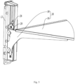
FIG 4 is a right view of part of the liner and the shelf assembly inFIG 1 ; -
FIG 5 is partially enlarged view of position A inFIG 4 ; -
FIG 6 is a perspective view of a slide rail in the shelf assembly inFIG 3 ; -
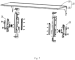
FIG 7 is an exploded perspective view of the shelf assembly inFIG 3 ; -
FIG 8 is an exploded perspective enlarged view of a moving device and a slide rail of the shelf assembly inFIG 7 ; -
FIG. 9 is an exploded perspective enlarged view of a mounting base, a damper and a gear of the moving device inFIG 8 ; -
FIG 10 is a perspective enlarged view of the mounting base inFIG 9 as viewed in another direction; -
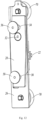
FIG 11 is an enlarged perspective view of the moving device of the shelf assembly inFIG 7 ; -
FIG. 12 is a perspective enlarged view of the moving device inFIG 11 as viewed in another direction; -
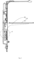
FIG. 13 is a right view of the shelf assembly inFIG 3 , whereupon a positioning member mates with a positioning portion; -
FIG. 14 is a partially enlarged view of position B inFIG 13 ; -
FIG. 15 is a right view of the shelf assembly inFIG 3 , whereupon a shelf device is lifted and inclined by a certain angle so that the positioning member is disengaged from the positioning portion; -
FIG. 16 is a partially enlarged view of position C inFIG 15 ; -
FIG. 17 is a partially enlarged perspective view of a shelf device in the shelf assembly inFIG 3 ; -
FIG. 18 is a view showing positional relationship between the shelf device and an upper hanger and a lower hanger inFIG 17 , whereupon the shelf device is an unoperated stated; -
FIG. 19 is a view showing positional relationship between the shelf device and an upper hanger and a lower hanger inFIG 18 , whereupon the shelf device is lifted vertically by a certain height so that the shelf device is disengages from the upper hanger and lower hanger. - The present invention will be described in detail in conjunction with specific embodiments shown in the figures. However, these embodiments are not intended to limit the present invention. Structural, methodological or functional variations made by those having ordinary skill in the art according to these embodiments are all included in the protection scope of the present invention. In the depictions of detailed embodiments of the present invention, the orientation or positional relationship indicated by terms such as "up", "down", "front", "rear", "left", "right", "vertical", "horizontal", "bottom", "in" and "out" etc. is the orientation or positional relationship based on the drawings, usually when a shelf assembly is in a normally-used state, and does not indicate that the specified positions or elements must have a specific orientation.
- As shown in
FIG 1 through FIG 5 , a specific embodiment of the present invention discloses a refrigerator. The refrigerator comprises a cabinet and a door body for opening/closing the cabinet. The cabinet comprises a housing and aliner 8 which defines a storage compartment. The refrigerator further comprises a shelf assembly. The shelf assembly comprises ashelf device 10 for placing articles and aslide rail 12. Theslide rail 12 forms a slideway in a vertical direction, and has at least two positioningportions 14 in vertical direction. - Specifically, in the preferred embodiment, the shelf assembly is disposed on the
liner 8. When the shelf assembly is disposed on theliner 8, theshelf device 10 comprises ashelf plate 16 for placing articles, whereupon theshelf plate 16 is usually a flat plate; Theslide rail 12 is disposed on theliner 8 and forms a slideway in the vertical direction, and has at least two positioningportions 14 in the vertical direction. - Certainly, the shelf component may also be disposed on the door body. When the shelf assembly is disposed on the
liner 8, theshelf device 10 comprises a bottle seat for containing articles. The bottle seat usually has receiving cavities for receiving articles, and the opening direction of the receiving cavities is usually upward; at this time, theslide rail 12 is disposed on the door body and forms a slideway in the vertical direction, and has at least two positioningportions 14 in the vertical direction. - Referring further to
FIG 6 through FIG 19 , the shelf assembly further comprises a movingdevice 18 for supporting theshelf device 10. A height of theshelf device 10 in the vertical direction is operably adjusted. Theslide rail 12 is provided with arack 20 extending in the vertical direction. The movingdevice 18 comprises agear 22 engaging with therack 20 and adamper 24 that generates damping against the rotation of thegear 22 in one of the directions. When the movingdevice 18 moves downward, thedamper 24 intervenes in damping to cause the movingdevice 18 to fall slowly. When the movingdevice 18 moves upward, thedamper 24 does not intervene in damping. With thedamper 24 generating one-way damping being provided, it is ensured that left and right sides of theshelf device 10 can move synchronously during upward movement and downward movement. Furthermore, the damper does not intervene in damping upon upward movement, theshelf device 10 can be moved upward more easily, thereby improving the user's experience effect. In addition, when theshelf device 10 and the movingdevice 18 move downward, thedamper 24 intervenes in damping, increases resistance so that it cannot occur that theshelf device 10 slides downward fast in a free-fall manner, such that theshelf device 18 moves down slowly, and the user's experience in use can be improved. - The moving
device 18 comprises a bearingplate 26 that is operably moved upward and downward relative to theslide rail 12, and a lockingplate 28 rotatably disposed relative to the bearingplate 26. Thegear 22 is rotatably disposed relative to the bearingplate 26, a positioningmember 30 is disposed on the lockingplate 28, and the lockingplate 28 engages with theshelf device 10. When theshelf device 10 is operably lifted or released, a positioningmember 30 is disengaged from or engaged with one of thepositioning portions 14, to adjust the height of theshelf device 10. In order to make the adjustment and fixation of theshelf device 10 more stable, twoslide rails 12 and two movingdevices 18 are provided on both sides of theshelf device 10 respectively. Then, detailed depictions will be presented by taking theslide rail 12 and the movingdevice 18 on one side as an example. - In the preferred embodiment, when the
shelf device 10 is lifted, theshelf device 10 is tilted upward at a certain angle, the lockingplate 28 rotates relative to the bearingplate 26, so that the positioningmember 30 is disengaged from the positioningportion 14, and then theshelf device 10 can be moved up or down to adjust the height. When theshelf device 10 is moved to a desired height, it will not be lifted again. As theshelf plate 16 returns to a horizontal state, the lockingplate 28 rotates in a direction opposite to the above direction relative to the bearingplate 26, so that the positioningmember 30 engages with thecorresponding positioning portion 14, thereby locking theshelf device 10 at a certain height. Therefore, the adjustment of theshelf device 10 is simple and convenient, and the cost is low. During the adjustment of the height of theshelf device 10, theshelf device 10 and the movingdevice 18 are never disengaged from theslide rail 12, and the articles on theshelf device 10 needn't be removed, thereby achieving the adjustment of the load and avoiding the user's unnecessary trouble during use. - Specifically, the locking
plate 28 is rotatably connected with the bearingplate 26 through arotating shaft 32. The lockingplate 28 is provided with anupper hanger 34 and alower hanger 36. Theshelf device 10 comprises asupport 38. Thesupport 38 is provided with an upper position-limitinghole 40 matting with theupper hanger 34 and a lower position-limitinghole 42 mating with thelower hanger 36. When theshelf device 10 is lifted, thesupport 38 drives the lockingplate 28 to rotate so that the positioningmember 30 is disengaged from the positioningportion 14. Thesupport 38 is also set in a pair. The twosupports 38 are fixedly connected with theshelf plate 16, the twosupports 38 are symmetrically disposed on both sides of theshelf plate 16, and thesupport 38 is perpendicular to theshelf plate 16. - The upper position-limiting
hole 40 comprises ahorizontal portion 44 extending in a horizontal direction and avertical portion 46 extending in a vertical direction. Thehorizontal portion 44 extends from thevertical portion 46 in a direction facing towards the user. The lower position-limitinghole 42 extends in the vertical direction. The upper position-limitinghole 40 and the lower positioning-limitinghole 42 both open downward. The opening of the upper position-limitinghole 40 is located at thevertical portion 46, and thevertical portion 46 of the upper position-limitinghole 40 is substantially located on the same vertical line as the lower position-limitinghole 42. When theshelf device 10 is in an unoperated state, namely, a released horizontal state, theupper hanger 34 is located at thevertical portion 46 of the upper position-limitinghole 40, and thelower hanger 36 is located at the lower position-limitinghole 42. When theshelf device 10 is detached, it is first lifted vertically and upwardly so that theupper hanger 34 is disengaged from the upper positioning-limitinghole 40 and thelower hanger 36 is disengaged from the lower position-limitinghole 42, and finally theshelf device 10 may be pulled outward horizontally and then detached, whereupon the movingdevice 18 is still on theslide rail 12. Therefore, theshelf device 10 can be detached very conveniently. When theshelf device 10 needed to cleaned, it may be detached individually. - The moving
device 18 comprises a mountingbase 48 fixedly connected to the bearingplate 26, thedamper 24 is disposed on the mountingbase 48, and a gear shaft of thegear 22 is connected to thedamper 24. Thedamper 24 and the mountingseat 48 are fixedly connected to the bearingplate 26 through two bolts 50, and thedamper 24 and the lockingplate 28 are respectively located on both sides of the bearingplate 26. Agroove 49 is disposed on a side of the mountingbase 48 away from the bearingplate 26, and thedamper 24 is at least partially received in thegroove 49. - The moving
device 18 further comprises anelastic member 52 that causes the positioningmember 30 to engage with thepositioning portion 14. In the present preferred embodiment, theelastic member 52 is set as a torsion spring. Certainly, theelastic member 52 may also be set as a tension spring, a compression spring or otherelastic member 52. One end of theelastic member 52 is connected to the bearingplate 26 or the mountingbase 48, and the other end of theelastic member 52 is connected to the positioningmember 30. Furthermore, the mountingbase 48 is provided with a receivinggroove 54 facing the bearingplate 26, and theelastic member 52 is partially located in the receivinggroove 54. In addition, theelastic member 52 is disposed on one of the bolts 50, so that the entire structure of the movingdevice 18 is made simpler and more compact. - When the height of the
shelf device 10 is adjusted, the user holds a front side of theshelf device 10 to lift it up. Here, the front side of theshelf device 10 refers to the side of theshelf device 10 facing the user. As the user lifts theshelf device 10, theshelf device 10 inclines upward at a certain angle, the lockingplate 28 rotates around the rotatingshaft 32 relative to the bearingplate 26, theupper hanger 34 enters thehorizontal portion 44 of the upper position-limitinghole 40, whereas thelower hanger 36 is always located in the lower position-limitinghole 42. After thelocking plate 28 rotates by a certain angle with respect to the bearingplate 26, the positioningmember 30 is disengaged from the positioningportion 14. At this time, theshelf device 10 may be moved up or down. At this time, theshelf device 10 and the movingdevice 18 together move up or down relative to theslide rail 12. After moving to the desired height, theshelf device 10 is no longer lifted. At this time, under the action of theelastic member 52, the lockingplate 28 rotates in a direction opposite to the above direction relative to the bearingplate 26, so that the locatingmember 30 engages with the corresponding locatingportion 14, thus locking theshelf device 10 at a certain height. At the same time, theupper hanger 34 engages with thevertical portion 46 of the upper position-limitinghole 40 again. - To make the installation of the
shelf device 10 more stable and reliable, anupper stop 56 is disposed at an end of theupper hanger 34, alower stop 58 is disposed at an end of thelower hanger 36, thesupport 38 is located between theupper stop 56 and the lockingplate 28, and thesupport 38 is also located between thelower stop 58 and the lockingplate 28. - Furthermore, a distance from the rotating
shaft 32 to thelower hanger 36 is greater than the distance from the rotatingshaft 32 to theupper hanger 34. The distance from the positioningmember 30 to therotating shaft 32 is greater than the distance from thelower hanger 36 to therotating shaft 32, and the positioningmember 30 is located at a lower end of the lockingplate 28. According to the above arrangement, the positioningmember 30 can disengaged from the positioningportion 14 in a way that the lockingplate 28 rotates by a small angle. That is, when the height of theshelf device 10 is adjusted, the locatingmember 30 can be disengaged from the positioningportion 14 as long as the front side of theshelf device 10 is lift a small distance. - Specifically, in the present embodiment, a triangle is defined by a center of the
rotating shaft 32, a center of theupper hanger 34 and a center of thelower hanger 36. - To make the rotation of the locking
plate 28 more stable, the bearingplate 26 is provided with an arc-shapedguide hole 60, which guides thelower hanger 36. Aguide pin 62 is disposed at an end of thelower hanger 36, and extends through the arc-shapedguide hole 60. - The positioning
member 30 is an L-shaped bent member extending from the lockingplate 28 towards a side of the lockingplate 28. The bearingplate 26 is provided with a through hole, the positioningmember 30 extends through the through hole, and the through hole is set to be square. - The number of the
positioning portions 14 is set to seven, so that theshelf device 10 has seven adjusting positions. Certainly, thepositioning portions 14 may also be set in other numbers. Specifically, the positioningportion 14 is set as a catching tooth which has ahorizontal support portion 64 and a catchinggroove 66. When theshelf device 10 is fixed at a certain height position, the positioningmember 30 is located in the catchinggroove 66 of thecorresponding positioning portion 14, and the positioningmember 30 is supported on thehorizontal support portion 64 of thecorresponding positioning portion 14. In addition, acircular arc transition 68 is disposed between two adjacent catching teeth, so that the positioningmember 30 can easily enter the corresponding catchinggroove 66 and prevent the occurrence of false catching. - In order to make the adjustment of the height of the
shelf device 10 more stable and easier, the movingdevice 18 further comprises two rollingbearings 70 located in the slideway. Preferably, both rollingbearings 70 employ noise-free bearings 70. As such, the resistance of theshelf device 10 in the adjustment process can be effectively reduce, the noise in the adjustment process be substantially reduced, and the comfort in the user's experience be improved. - It should be understood that although the description is described according to the embodiments, not every embodiment only comprises one independent technical solution, that such a description manner is only for the sake of clarity, that those skilled in the art should take the description as an integral part, and that the technical solutions in the embodiments may be suitably combined to form other embodiments understandable by those skilled in the art. The detailed descriptions set forth above are merely specific illustrations of feasible embodiments of the present invention, and are not intended to limit the scope of protection of the present invention. All equivalent embodiments or modifications that do not depart from the art spirit of the present invention should fall within the scope of protection of the present invention.
Claims (10)
- A shelf assembly for a refrigerator, comprising:a shelf device for placing articles;a slide rail forming a slideway in a vertical direction, and having at least two positioning portions in a vertical direction;wherein the shelf assembly further comprises:
a moving device for supporting the shelf device, the moving device comprising a bearing plate that is operably moved upward and downward relative to the slide rail, and a locking plate rotatably disposed relative to the bearing plate, a positioning member being disposed on the locking plate, the locking plate engaging with the shelf device; when the shelf device is operably lifted or released, a positioning member is disengaged from or engaged with one of the positioning portions, to adjust the height of the shelf device. - The shelf assembly according to claim 1, wherein the locking plate is rotatably connected with the bearing plate through a rotating shaft, the locking plate is provided with an upper hanger and a lower hanger, the shelf device comprises a support, and the support is provided with an upper position-limiting hole matting with the upper hanger and a lower position-limiting hole mating with the lower hanger; when the shelf device is lifted, the support drives the locking plate to rotate so that the positioning member is disengaged from the positioning portion.
- The shelf assembly according to claim 2, wherein the upper position-limiting hole comprises a horizontal portion extending in a horizontal direction and a vertical portion extending in a vertical direction, the horizontal portion extends from the vertical portion in a direction facing towards the user, the lower position-limiting hole extends in the vertical direction, the upper position-limiting hole and the lower positioning-limiting hole are both set to be open-ended, and the upper position-limiting hole and the lower positioning-limiting hole both open downward.
- The shelf assembly according to claim 2, wherein a distance from the rotating shaft to the lower hanger is greater than the distance from the rotating shaft to the upper hanger.
- The shelf assembly according to claim 2, wherein a triangle is defined by a center of the rotating shaft, a center of the upper hanger and a center of the lower hanger.
- The shelf assembly according to claim 2, wherein the bearing plate is provided with an arc-shaped guide hole, which guides the lower hanger.
- The shelf assembly according to claim 1, wherein the moving device comprises two rolling bearings located in the slideway.
- The shelf assembly according to claim 7, wherein the rolling bearings employ noise-free bearings.
- A refrigerator, comprising a cabinet and a door body for opening/closing the cabinet, the cabinet comprising a housing and a liner, the liner defining a storage chamber, the refrigerator further comprising a shelf assembly disposed on the liner, the shelf assembly comprising:a shelf device comprising a shelf plate for placing articles;a slide rail being disposed on the liner and forming a slideway in the vertical direction, and having at least two positioning portions in the vertical direction;wherein the shelf assembly further comprises a moving device for supporting the shelf device, the moving device comprises a bearing plate that is operably moved upward and downward relative to the slide rail, and a locking plate rotatably disposed relative to the bearing plate, a positioning member is disposed on the locking plate, and the locking plate engages with the shelf device; when the shelf device is operably lifted or released, the positioning member is disengaged from or engaged with one of the positioning portions, to adjust the height of the shelf device.
- A refrigerator, comprising a cabinet and a door body for opening/closing the cabinet, the cabinet defining a storage chamber, the refrigerator further comprising a shelf assembly disposed on the door body, the shelf assembly comprising:a shelf device comprising a bottle seat for containing articles;a slide rail being disposed on the door body and forming a slideway in a vertical direction, and having at least two positioning portions in the vertical direction;wherein the shelf assembly further comprises a moving device for supporting the shelf device, the moving device comprises a bearing plate that is operably moved upward and downward relative to the slide rail, and a locking plate rotatably disposed relative to the bearing plate, a positioning member is disposed on the locking plate, and the locking plate engages with the shelf device; when the shelf device is operably lifted or released, the positioning member is disengaged from or engaged with one of the positioning portions, to adjust the height of the shelf device.
Applications Claiming Priority (2)
| Application Number | Priority Date | Filing Date | Title |
|---|---|---|---|
| CN202010667412.6A CN113932542B (en) | 2020-07-13 | 2020-07-13 | Shelf assembly for refrigerator and refrigerator |
| PCT/CN2021/105690 WO2022012457A1 (en) | 2020-07-13 | 2021-07-12 | Shelf assembly for refrigerator and refrigerator |
Publications (4)
| Publication Number | Publication Date |
|---|---|
| EP4180753A1 true EP4180753A1 (en) | 2023-05-17 |
| EP4180753A4 EP4180753A4 (en) | 2023-12-27 |
| EP4180753B1 EP4180753B1 (en) | 2025-12-17 |
| EP4180753C0 EP4180753C0 (en) | 2025-12-17 |
Family
ID=79273505
Family Applications (1)
| Application Number | Title | Priority Date | Filing Date |
|---|---|---|---|
| EP21842326.7A Active EP4180753B1 (en) | 2020-07-13 | 2021-07-12 | Shelf assembly for refrigerator and refrigerator |
Country Status (5)
| Country | Link |
|---|---|
| US (1) | US12163729B2 (en) |
| EP (1) | EP4180753B1 (en) |
| CN (1) | CN113932542B (en) |
| AU (1) | AU2021310164B2 (en) |
| WO (1) | WO2022012457A1 (en) |
Families Citing this family (4)
| Publication number | Priority date | Publication date | Assignee | Title |
|---|---|---|---|---|
| CN114076485B (en) * | 2020-08-19 | 2023-02-17 | 青岛海尔电冰箱有限公司 | Adjustable shelf device and refrigerator having the same |
| CN115164503A (en) * | 2022-06-28 | 2022-10-11 | 青岛海尔电冰箱有限公司 | Rack assembly and refrigerator with same |
| WO2025108385A1 (en) * | 2023-11-21 | 2025-05-30 | 青岛海尔电冰箱有限公司 | Refrigeration apparatus |
| WO2025218484A1 (en) * | 2024-04-17 | 2025-10-23 | 青岛海尔电冰箱有限公司 | Shelf assembly and refrigeration device |
Family Cites Families (19)
| Publication number | Priority date | Publication date | Assignee | Title |
|---|---|---|---|---|
| EP0619464A1 (en) * | 1993-04-08 | 1994-10-12 | Liebherr-Hausgeräte Gmbh | Refrigerator |
| WO2003091643A1 (en) * | 2002-04-25 | 2003-11-06 | Kabushiki Kaisha Toshiba | Shelving unit and refrigerator having the same |
| US7337730B2 (en) * | 2003-01-31 | 2008-03-04 | Gemtron Corporation | Vertically adjustable shelves and refrigerator compartment housing the same |
| US20050162055A1 (en) * | 2003-01-31 | 2005-07-28 | Gemtron Corporation | Vertically adjustable shelves and refrigerator compartment housing the same |
| WO2008062991A1 (en) * | 2006-11-20 | 2008-05-29 | Lg Electronics Inc. | Height adjusting apparatus of shelf for refrigerator |
| DE102008014885A1 (en) * | 2008-03-19 | 2009-09-24 | BSH Bosch und Siemens Hausgeräte GmbH | Refrigerating appliance and associated latching means arrangement for retrofitting |
| US8960825B2 (en) * | 2011-10-04 | 2015-02-24 | Lg Electronics Inc. | Refrigerator |
| CN104374143B (en) * | 2013-08-12 | 2017-03-29 | 海尔集团公司 | Refrigerator governor motion and refrigerator |
| CN104729218A (en) * | 2013-12-23 | 2015-06-24 | 海尔集团公司 | Adjustable shelf and refrigeration equipment |
| CN104344675B (en) * | 2014-02-08 | 2016-11-23 | 海尔集团公司 | Rack component and there is the refrigerator of this rack component |
| EP3015802B1 (en) * | 2014-08-12 | 2018-03-28 | LG Electronics Inc. | Refrigerator |
| CN204574689U (en) * | 2015-03-27 | 2015-08-19 | 海信(山东)冰箱有限公司 | A kind of refrigerator and shelves high adjusting device thereof |
| CN106382787B (en) | 2016-11-01 | 2019-03-19 | 泰州乐金电子冷机有限公司 | Height-adjustable refrigerator shelf |
| KR102591763B1 (en) * | 2016-11-04 | 2023-10-23 | 삼성전자주식회사 | Refrigerator |
| TR201706501A2 (en) * | 2017-05-03 | 2018-11-21 | Arcelik As | HEIGHT ADJUSTABLE BODY SHELF CONTAINER REFRIGERATOR |
| CN111380316A (en) * | 2018-12-28 | 2020-07-07 | 青岛海尔股份有限公司 | Adjustable shelf and refrigerator using the same |
| CN109764623B (en) * | 2018-12-28 | 2020-12-04 | 海尔智家股份有限公司 | Adjustable shelf and refrigerator using the same |
| CN111380318A (en) * | 2018-12-28 | 2020-07-07 | 青岛海尔股份有限公司 | Adjustable rack and refrigerator using same |
| CN110513941A (en) * | 2019-09-23 | 2019-11-29 | 佛山市云米电器科技有限公司 | A hidden installation structure of a shelf and a refrigerator using the same |
-
2020
- 2020-07-13 CN CN202010667412.6A patent/CN113932542B/en active Active
-
2021
- 2021-07-12 EP EP21842326.7A patent/EP4180753B1/en active Active
- 2021-07-12 WO PCT/CN2021/105690 patent/WO2022012457A1/en not_active Ceased
- 2021-07-12 US US18/016,329 patent/US12163729B2/en active Active
- 2021-07-12 AU AU2021310164A patent/AU2021310164B2/en active Active
Also Published As
| Publication number | Publication date |
|---|---|
| EP4180753B1 (en) | 2025-12-17 |
| US12163729B2 (en) | 2024-12-10 |
| US20230280089A1 (en) | 2023-09-07 |
| CN113932542A (en) | 2022-01-14 |
| CN113932542B (en) | 2022-12-16 |
| EP4180753C0 (en) | 2025-12-17 |
| WO2022012457A1 (en) | 2022-01-20 |
| AU2021310164B2 (en) | 2024-05-02 |
| EP4180753A4 (en) | 2023-12-27 |
| AU2021310164A1 (en) | 2023-03-02 |
Similar Documents
| Publication | Publication Date | Title |
|---|---|---|
| AU2021310164B2 (en) | Shelf assembly for refrigerator and refrigerator | |
| CA2699699C (en) | Stabilizing assembly of drawable carrier | |
| US7731314B2 (en) | Door assembly and refrigerator using the same | |
| KR20230062481A (en) | Refrigerator and lift up drawer for refrigerator | |
| US9464841B2 (en) | Refrigerator | |
| CN106196866B (en) | Refrigerator | |
| TWI229180B (en) | Shelving unit and refrigerator having the same | |
| US20050062380A1 (en) | Shelf height adjuster of refrigerator | |
| EP1862723A2 (en) | Monitor stand | |
| KR102583877B1 (en) | Refrigerator | |
| CN113932543B (en) | Shelf assembly for refrigerator and refrigerator | |
| CN116026093B (en) | Refrigerator with a refrigerator body | |
| JP2003322465A (en) | refrigerator | |
| CN116086116B (en) | Drawer assembly and refrigerator | |
| US11898793B2 (en) | Vertical displacement stopping system | |
| CN107192212B (en) | Refrigerator drawer capable of automatically adjusting cooling capacity and refrigerator | |
| WO2006090342A1 (en) | A cooling device | |
| KR101654933B1 (en) | Drawer for refrigerator | |
| CN116164482B (en) | Door body and refrigerator | |
| CN221898071U (en) | Turnover drawer and refrigerator thereof | |
| CN114508893A (en) | Drawer assembly and refrigeration equipment comprising same | |
| JP3704964B2 (en) | Lifting storage device and lifting storage cabinet | |
| CN216745076U (en) | Refrigeration device | |
| JP2005006969A (en) | Shelf device and refrigerator with shelf device | |
| CN116222123A (en) | Drawer assemblies and refrigerators |
Legal Events
| Date | Code | Title | Description |
|---|---|---|---|
| STAA | Information on the status of an ep patent application or granted ep patent |
Free format text: STATUS: THE INTERNATIONAL PUBLICATION HAS BEEN MADE |
|
| PUAI | Public reference made under article 153(3) epc to a published international application that has entered the european phase |
Free format text: ORIGINAL CODE: 0009012 |
|
| STAA | Information on the status of an ep patent application or granted ep patent |
Free format text: STATUS: REQUEST FOR EXAMINATION WAS MADE |
|
| 17P | Request for examination filed |
Effective date: 20230113 |
|
| AK | Designated contracting states |
Kind code of ref document: A1 Designated state(s): AL AT BE BG CH CY CZ DE DK EE ES FI FR GB GR HR HU IE IS IT LI LT LU LV MC MK MT NL NO PL PT RO RS SE SI SK SM TR |
|
| DAV | Request for validation of the european patent (deleted) | ||
| DAX | Request for extension of the european patent (deleted) | ||
| A4 | Supplementary search report drawn up and despatched |
Effective date: 20231123 |
|
| RIC1 | Information provided on ipc code assigned before grant |
Ipc: F25D 25/04 20060101ALN20231117BHEP Ipc: A47B 96/06 20060101ALN20231117BHEP Ipc: A47F 3/04 20060101ALI20231117BHEP Ipc: A47B 57/52 20060101ALI20231117BHEP Ipc: A47B 51/00 20060101ALI20231117BHEP Ipc: F25D 23/06 20060101ALI20231117BHEP Ipc: F25D 25/02 20060101AFI20231117BHEP |
|
| GRAP | Despatch of communication of intention to grant a patent |
Free format text: ORIGINAL CODE: EPIDOSNIGR1 |
|
| STAA | Information on the status of an ep patent application or granted ep patent |
Free format text: STATUS: GRANT OF PATENT IS INTENDED |
|
| RIC1 | Information provided on ipc code assigned before grant |
Ipc: F25D 25/02 20060101AFI20250704BHEP Ipc: F25D 23/06 20060101ALI20250704BHEP Ipc: A47B 51/00 20060101ALI20250704BHEP Ipc: A47B 57/52 20060101ALI20250704BHEP Ipc: A47F 3/04 20060101ALI20250704BHEP Ipc: A47B 96/06 20060101ALN20250704BHEP Ipc: F25D 25/04 20060101ALN20250704BHEP |
|
| INTG | Intention to grant announced |
Effective date: 20250716 |
|
| GRAS | Grant fee paid |
Free format text: ORIGINAL CODE: EPIDOSNIGR3 |
|
| GRAA | (expected) grant |
Free format text: ORIGINAL CODE: 0009210 |
|
| STAA | Information on the status of an ep patent application or granted ep patent |
Free format text: STATUS: THE PATENT HAS BEEN GRANTED |
|
| AK | Designated contracting states |
Kind code of ref document: B1 Designated state(s): AL AT BE BG CH CY CZ DE DK EE ES FI FR GB GR HR HU IE IS IT LI LT LU LV MC MK MT NL NO PL PT RO RS SE SI SK SM TR |
|
| RAP3 | Party data changed (applicant data changed or rights of an application transferred) |
Owner name: QINGDAO HAIER REFRIGERATOR CO., LTD. Owner name: HAIER SMART HOME CO., LTD. |
|
| REG | Reference to a national code |
Ref country code: CH Ref legal event code: F10 Free format text: ST27 STATUS EVENT CODE: U-0-0-F10-F00 (AS PROVIDED BY THE NATIONAL OFFICE) Effective date: 20251217 Ref country code: GB Ref legal event code: FG4D |
|
| REG | Reference to a national code |
Ref country code: DE Ref legal event code: R096 Ref document number: 602021044705 Country of ref document: DE |
|
| U01 | Request for unitary effect filed |
Effective date: 20260112 |
|
| U07 | Unitary effect registered |
Designated state(s): AT BE BG DE DK EE FI FR IT LT LU LV MT NL PT RO SE SI Effective date: 20260119 |
|
| PG25 | Lapsed in a contracting state [announced via postgrant information from national office to epo] |
Ref country code: NO Free format text: LAPSE BECAUSE OF FAILURE TO SUBMIT A TRANSLATION OF THE DESCRIPTION OR TO PAY THE FEE WITHIN THE PRESCRIBED TIME-LIMIT Effective date: 20260317 |
|
| PG25 | Lapsed in a contracting state [announced via postgrant information from national office to epo] |
Ref country code: HR Free format text: LAPSE BECAUSE OF FAILURE TO SUBMIT A TRANSLATION OF THE DESCRIPTION OR TO PAY THE FEE WITHIN THE PRESCRIBED TIME-LIMIT Effective date: 20251217 |
|
| PG25 | Lapsed in a contracting state [announced via postgrant information from national office to epo] |
Ref country code: RS Free format text: LAPSE BECAUSE OF FAILURE TO SUBMIT A TRANSLATION OF THE DESCRIPTION OR TO PAY THE FEE WITHIN THE PRESCRIBED TIME-LIMIT Effective date: 20260317 |
|
| PG25 | Lapsed in a contracting state [announced via postgrant information from national office to epo] |
Ref country code: SM Free format text: LAPSE BECAUSE OF FAILURE TO SUBMIT A TRANSLATION OF THE DESCRIPTION OR TO PAY THE FEE WITHIN THE PRESCRIBED TIME-LIMIT Effective date: 20251217 |
|
| PG25 | Lapsed in a contracting state [announced via postgrant information from national office to epo] |
Ref country code: ES Free format text: LAPSE BECAUSE OF FAILURE TO SUBMIT A TRANSLATION OF THE DESCRIPTION OR TO PAY THE FEE WITHIN THE PRESCRIBED TIME-LIMIT Effective date: 20251217 |
|
| PG25 | Lapsed in a contracting state [announced via postgrant information from national office to epo] |
Ref country code: PL Free format text: LAPSE BECAUSE OF FAILURE TO SUBMIT A TRANSLATION OF THE DESCRIPTION OR TO PAY THE FEE WITHIN THE PRESCRIBED TIME-LIMIT Effective date: 20251217 |
|
| PG25 | Lapsed in a contracting state [announced via postgrant information from national office to epo] |
Ref country code: IS Free format text: LAPSE BECAUSE OF FAILURE TO SUBMIT A TRANSLATION OF THE DESCRIPTION OR TO PAY THE FEE WITHIN THE PRESCRIBED TIME-LIMIT Effective date: 20260417 |
|
| PG25 | Lapsed in a contracting state [announced via postgrant information from national office to epo] |
Ref country code: CZ Free format text: LAPSE BECAUSE OF FAILURE TO SUBMIT A TRANSLATION OF THE DESCRIPTION OR TO PAY THE FEE WITHIN THE PRESCRIBED TIME-LIMIT Effective date: 20251217 |
|
| PG25 | Lapsed in a contracting state [announced via postgrant information from national office to epo] |
Ref country code: SK Free format text: LAPSE BECAUSE OF FAILURE TO SUBMIT A TRANSLATION OF THE DESCRIPTION OR TO PAY THE FEE WITHIN THE PRESCRIBED TIME-LIMIT Effective date: 20251217 |
|
| U20 | Renewal fee for the european patent with unitary effect paid |
Year of fee payment: 6 Effective date: 20260626 |