EP4180675A1 - Spannvorrichtung - Google Patents
Spannvorrichtung Download PDFInfo
- Publication number
- EP4180675A1 EP4180675A1 EP22193928.3A EP22193928A EP4180675A1 EP 4180675 A1 EP4180675 A1 EP 4180675A1 EP 22193928 A EP22193928 A EP 22193928A EP 4180675 A1 EP4180675 A1 EP 4180675A1
- Authority
- EP
- European Patent Office
- Prior art keywords
- clamping
- clamping device
- orifice
- angle
- bearing surface
- Prior art date
- Legal status (The legal status is an assumption and is not a legal conclusion. Google has not performed a legal analysis and makes no representation as to the accuracy of the status listed.)
- Granted
Links
Images


Classifications
-
- F—MECHANICAL ENGINEERING; LIGHTING; HEATING; WEAPONS; BLASTING
- F16—ENGINEERING ELEMENTS AND UNITS; GENERAL MEASURES FOR PRODUCING AND MAINTAINING EFFECTIVE FUNCTIONING OF MACHINES OR INSTALLATIONS; THERMAL INSULATION IN GENERAL
- F16B—DEVICES FOR FASTENING OR SECURING CONSTRUCTIONAL ELEMENTS OR MACHINE PARTS TOGETHER, e.g. NAILS, BOLTS, CIRCLIPS, CLAMPS, CLIPS OR WEDGES; JOINTS OR JOINTING
- F16B5/00—Joining sheets or plates, e.g. panels, to one another or to strips or bars parallel to them
- F16B5/06—Joining sheets or plates, e.g. panels, to one another or to strips or bars parallel to them by means of clamps or clips
- F16B5/0607—Joining sheets or plates, e.g. panels, to one another or to strips or bars parallel to them by means of clamps or clips joining sheets or plates to each other
- F16B5/0621—Joining sheets or plates, e.g. panels, to one another or to strips or bars parallel to them by means of clamps or clips joining sheets or plates to each other in parallel relationship
- F16B5/0642—Joining sheets or plates, e.g. panels, to one another or to strips or bars parallel to them by means of clamps or clips joining sheets or plates to each other in parallel relationship the plates being arranged one on top of the other and in full close contact with each other
-
- F—MECHANICAL ENGINEERING; LIGHTING; HEATING; WEAPONS; BLASTING
- F16—ENGINEERING ELEMENTS AND UNITS; GENERAL MEASURES FOR PRODUCING AND MAINTAINING EFFECTIVE FUNCTIONING OF MACHINES OR INSTALLATIONS; THERMAL INSULATION IN GENERAL
- F16B—DEVICES FOR FASTENING OR SECURING CONSTRUCTIONAL ELEMENTS OR MACHINE PARTS TOGETHER, e.g. NAILS, BOLTS, CIRCLIPS, CLAMPS, CLIPS OR WEDGES; JOINTS OR JOINTING
- F16B19/00—Bolts without screw-thread; Pins, including deformable elements; Rivets
- F16B19/04—Rivets; Spigots or the like fastened by riveting
- F16B19/08—Hollow rivets; Multi-part rivets
- F16B19/10—Hollow rivets; Multi-part rivets fastened by expanding mechanically
- F16B19/1027—Multi-part rivets
- F16B19/1036—Blind rivets
- F16B19/1045—Blind rivets fastened by a pull - mandrel or the like
- F16B19/1072—Blind rivets fastened by a pull - mandrel or the like the pull-mandrel or the like comprising a thread and being rotated with respect to the rivet, thereby mechanically expanding and fastening the rivet
-
- F—MECHANICAL ENGINEERING; LIGHTING; HEATING; WEAPONS; BLASTING
- F16—ENGINEERING ELEMENTS AND UNITS; GENERAL MEASURES FOR PRODUCING AND MAINTAINING EFFECTIVE FUNCTIONING OF MACHINES OR INSTALLATIONS; THERMAL INSULATION IN GENERAL
- F16B—DEVICES FOR FASTENING OR SECURING CONSTRUCTIONAL ELEMENTS OR MACHINE PARTS TOGETHER, e.g. NAILS, BOLTS, CIRCLIPS, CLAMPS, CLIPS OR WEDGES; JOINTS OR JOINTING
- F16B19/00—Bolts without screw-thread; Pins, including deformable elements; Rivets
- F16B19/04—Rivets; Spigots or the like fastened by riveting
- F16B19/08—Hollow rivets; Multi-part rivets
- F16B19/10—Hollow rivets; Multi-part rivets fastened by expanding mechanically
- F16B19/1027—Multi-part rivets
- F16B19/1036—Blind rivets
- F16B19/109—Temporary rivets, e.g. with a spring-loaded pin
-
- F—MECHANICAL ENGINEERING; LIGHTING; HEATING; WEAPONS; BLASTING
- F16—ENGINEERING ELEMENTS AND UNITS; GENERAL MEASURES FOR PRODUCING AND MAINTAINING EFFECTIVE FUNCTIONING OF MACHINES OR INSTALLATIONS; THERMAL INSULATION IN GENERAL
- F16B—DEVICES FOR FASTENING OR SECURING CONSTRUCTIONAL ELEMENTS OR MACHINE PARTS TOGETHER, e.g. NAILS, BOLTS, CIRCLIPS, CLAMPS, CLIPS OR WEDGES; JOINTS OR JOINTING
- F16B21/00—Means for preventing relative axial movement of a pin, spigot, shaft or the like and a member surrounding it; Stud-and-socket releasable fastenings
- F16B21/10—Means for preventing relative axial movement of a pin, spigot, shaft or the like and a member surrounding it; Stud-and-socket releasable fastenings by separate parts
-
- F—MECHANICAL ENGINEERING; LIGHTING; HEATING; WEAPONS; BLASTING
- F16—ENGINEERING ELEMENTS AND UNITS; GENERAL MEASURES FOR PRODUCING AND MAINTAINING EFFECTIVE FUNCTIONING OF MACHINES OR INSTALLATIONS; THERMAL INSULATION IN GENERAL
- F16B—DEVICES FOR FASTENING OR SECURING CONSTRUCTIONAL ELEMENTS OR MACHINE PARTS TOGETHER, e.g. NAILS, BOLTS, CIRCLIPS, CLAMPS, CLIPS OR WEDGES; JOINTS OR JOINTING
- F16B37/00—Nuts or like thread-engaging members
- F16B37/14—Cap nuts; Nut caps or bolt caps
- F16B37/145—Sleeve nuts, e.g. combined with bolts
Definitions
- the invention relates to the field of clamping devices intended to clamp a first part against a second part, the first and second parts each having an orifice.
- the clamping device comprises a sleeve adapted to be inserted into the holes of the parts.
- the device includes an actuation unit and a stem actuated by the actuation unit.
- the clamping device also comprises an anchoring element interacting with the actuator.
- the anchoring element comprises two obliquely cut cylinders, the lower cylinder being fixed to the rod.
- the actuation unit may in particular be a nut connected with the rod by screwing.
- the actuation of the actuation unit makes it possible to raise the rod causing the lower cylinder to rise.
- the lower cylinder then exerts a force on the upper cylinder which tends to move the upper cylinder radially.
- One idea underlying the invention is to improve the application of a clamping force with a screw clamping device.
- the rolling bearing makes it possible, when screwing in the actuating element, to prevent the actuating element from rubbing against the part to be tightened or even against the sleeve so that same tightening torque exerted on the actuating element the tightening force exerted by the tightening element against the edges of the second orifice is greater.
- such a rolling bearing makes it possible to prevent the actuation unit from causing the sleeve to rotate when the tightening torque is applied.
- such a clamping device may comprise one or more of the following characteristics.
- the rolling bodies are needles having an axis of revolution extending in a radial direction.
- the collar is made at a first end of the cylindrical body and the cylindrical body has a second end, the second end being provided with the second inclined bearing surface.
- the clamping element has a trapezoidal radial section comprising a small base located opposite the threaded rod, a large base, a first side and a second side, the first side and the second side connecting the large base to the small base, the first side facing the first surface inclined support and the second side being opposite the second inclined support surface.
- the first inclined bearing surface and the second inclined bearing surface have a frustoconical shape of revolution around the axis of rotation X and respectively have a first half-angle at the apex and a second half-angle.
- apex angle, the first apex half-angle and the second apex half-angle each being between 30 and 60°.
- the first apex half-angle and the second apex half-angle are each equal to 45°.
- the forces exerted by the clamping element have two components, one radial making it possible to exert a clamping force against the edges of the orifice of the second part, the other axial pressing the clamping device against the first piece.
- the first side has a frustoconical shape of revolution around the axis of rotation X which has a half-angle at the top equal to the first half-angle at the top of the first inclined support surface.
- the second side has a frustoconical shape of revolution around the axis of rotation X which has a half-angle at the top equal to the second half-angle at the top of the second inclined bearing surface.
- the first vertex half-angle is equal to the second vertex half-angle.
- the at least one clamping element is made of a metallic material.
- the at least one clamping element is made of hardened steel or stainless steel.
- the clamping device comprises at least two clamping elements, distributed in a plane normal to the axis of rotation and arranged around the threaded screw.
- the clamping device comprises three clamping elements, distributed in a plane normal to the axis of rotation and arranged around the threaded screw.
- each clamping element has an angular section equal to 120° so that the assembly of the three clamping elements forms a ring.
- the clamping elements are connected to each other using an elastic ring arranged around said clamping elements, the elastic ring exerting a radial return force oriented in the direction of the threaded rod on the clamping elements.
- the extensible ring is made of an elastomeric material, such as rubber.
- the rolling bearing comprises an upper ring located against the actuating element and a lower ring resting against the collar, the rolling bodies being interposed between the upper ring and the lower ring.
- the invention also provides a clamping assembly comprising a first part, a second part respectively having a first orifice and a second orifice and an aforementioned clamping device, the clamping device being inserted into the first orifice and the second hole and being configured to tighten the first part and the second part against each other, the threaded rod passing through the first hole, the screw head and the at least one clamping element being housed in the second hole .
- the second part is a work table.
- a clamping device 1 making it possible to clamp a first part 2 provided with a first orifice 3 against a second part 4 provided with a second orifice 5.
- FIG. 1 shows a clamping device 1 according to one embodiment which is housed in the first orifice 3 and the second orifice 5.
- the orifices 3, 5 are coaxial.
- the orifices 3, 5 may have different diameters, the diameter of the second orifice 5 being preferably less than or equal to the diameter of the first orifice 3.
- the second part 4 may for example be a work table serving as a support for workpieces .
- FIG. 1 shows a cross-section of the clamping device 1 according to one embodiment making it possible to visualize the various elements making up the clamping device 1.
- the rotation of the actuating element 9 around the X axis makes it possible to move the threaded screw 7 axially along the X axis so as to bring the screw head 8 closer to the sleeve 11 during tightening or to move the screw head 8 of sleeve 11 when loosening.
- the screw head 8 has a first bearing surface 18 arranged facing the clamping elements 15 which has a frustoconical shape of revolution around the axis of rotation X having a half-angle 34 at the vertex equal to 45°.
- the cylindrical body 12 has a second bearing surface 19 arranged facing the clamping elements 15 which has a frustoconical shape of revolution around the axis of rotation X having a half-angle 35 at the apex equal to 45 °.
- the bearing surfaces 18, 19 may have a half-angle at the top different from 45° and advantageously between 30 and 60°.
- each clamping element 15 has a generally trapezoidal radial section comprising a small base 20 located opposite the threaded rod 7, a large base 21, a first side 22 and a second side 23.
- the first side 22 and the second side 23 connect the large base 21 to the small base 20, the first side 22 being opposite the first inclined support surface 18 and the second side 23 being opposite the second support surface inclined 19.
- the clamping elements 15 are configured to move radially away from the threaded rod 7 when bringing the screw head 8 towards the sleeve 11. Indeed, due to the inclination of the bearing surfaces 18 and 19 , the clamping elements 15 are pushed radially outward during clamping.
- the clamping elements 15 are three in number and are distributed all around the threaded screw 6 so as to form a clamping ring.
- the first side 22 has a frustoconical shape of revolution around the axis of rotation X which has a half-angle at the top equal to the half-angle at the top of the first inclined surface 18.
- the second side 23 has a frustoconical shape of revolution around the axis of rotation X which has a half-angle at the top equal to the second half-angle at the top of the second inclined surface 19.
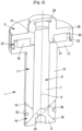
- the surface formed at the level of the large base 21 of the clamping elements 15 comprises a groove 24, visible in picture 3 , and which accommodates an elastic ring 25 of annular shape.
- the elastic ring 25, shown in figure 2 makes it possible to connect the clamping elements 15 to each other while maintaining them around the threaded screw 6.
- the elastic ring 25 makes it possible to exert a radial return force oriented in the direction of the threaded rod 7 on the clamping elements 15 so as to reposition the clamping elements 15 close to the threaded rod 7 when the clamping device 1 is loosened.
- the rolling bearing 16 here comprises an upper ring 26, a lower ring 27, and rolling bodies 17 made in the form of needles which are interposed between the upper ring 26 and the lower ring 27.
- the needles 17 can be held together with a cage.
- the needles 17 are made in the form of a cylinder whose axis of revolution is oriented along the radial direction of the clamping device 1.
- the upper ring 26 is located against the actuating element 9 while the lower ring 27 rests against the flange 13.
- the rolling bearing 16 can also be made in the form of a needle cage, that is to say that here the rolling bearing 16 does not have a ring , the needles 17 being on the one hand in contact with the actuating element 9 and on the other hand in contact with the collar 13.
- the actuating element 9 is, in the example shown in figure 2 , formed of a flat annular portion 28 through which the threaded hole 10 passes and surmounted by a cap 29 configured to cooperate with a tightening tool.
- the actuating element 9 also has a peripheral skirt 30 made all around the planar annular portion 28. The outer surface of the peripheral skirt 30 can advantageously be roughened by so as to facilitate tightening, which can initially be done manually.
- the actuating element 9 also comprises a protuberance 31 projecting from the planar annular portion 28 towards the inside of the clamping device 1.
- the rolling bearing 16 is held radially, on the one hand, on the inside by the protrusion 31 of the actuating element and, on the other hand, on the outside, by a radial abutment 32 projecting from the collar 13 towards the outside of the clamping device 1.
- the radial abutment 32 has an annular shape, is located all around the roller bearing 16 and cooperates with the peripheral skirt 30 so as to form a seal 33.
- the peripheral skirt 30 has the shape of a hook cooperating with a counter hook formed by the radial stop 32 so as to prevent external elements such as dust from entering the clamping device 1.
- a method of using such a clamping device 1 for clamping a second part 4 on a first part 2 is described below.
- the first part 2 is first of all placed against the second part 4 so that the first orifice 3 and the second orifice 5 are coaxial.
- the clamping device 1 is then introduced into the orifices 3, 5 until the flange 13 is placed against the edges 14 of the first orifice 3, the clamping elements 15 and the screw head 8 thus being positioned in the second hole 5.
- the actuating element 9 is then actuated manually or using a tightening tool engaged on the cap 29 so as to screw the threaded rod 7 into the tapped hole 10.
- the screwing causes the head to rise screw 8 in the direction of the sleeve 11.
- the clamping elements 15 are thus gripped between the bearing surfaces 18, 19 of the screw head 8 and the sleeve 11 so as to be moved radially outwards.
- the surface formed by the large base 21 of the clamping elements 15 then exerts forces against the walls of the second orifice 5 oriented at an angle of 45° with respect to the radial direction.
- the forces exerted by the clamping elements 15 thus have two components, one radial making it possible to exert a clamping force against the walls of the second orifice 5 of the second part 4, the other axial pressing the flange 13 against the first piece 2.
- the actuating element 9 is actuated so as to unscrew the threaded rod from the tapped hole 10.
- the unscrewing causes, under the effect of the elasticity of the ring 25, the return to position clamping elements 15 which does not exert then more force against the walls of the second orifice 5 then allowing the clamping device 1 to be removed.
Landscapes
- Engineering & Computer Science (AREA)
- General Engineering & Computer Science (AREA)
- Mechanical Engineering (AREA)
- Clamps And Clips (AREA)
Applications Claiming Priority (1)
| Application Number | Priority Date | Filing Date | Title |
|---|---|---|---|
| FR2111994A FR3129184B1 (fr) | 2021-11-12 | 2021-11-12 | Dispositif de serrage |
Publications (3)
| Publication Number | Publication Date |
|---|---|
| EP4180675A1 true EP4180675A1 (de) | 2023-05-17 |
| EP4180675C0 EP4180675C0 (de) | 2024-05-15 |
| EP4180675B1 EP4180675B1 (de) | 2024-05-15 |
Family
ID=79602125
Family Applications (1)
| Application Number | Title | Priority Date | Filing Date |
|---|---|---|---|
| EP22193928.3A Active EP4180675B1 (de) | 2021-11-12 | 2022-09-05 | Spannvorrichtung |
Country Status (2)
| Country | Link |
|---|---|
| EP (1) | EP4180675B1 (de) |
| FR (1) | FR3129184B1 (de) |
Cited By (2)
| Publication number | Priority date | Publication date | Assignee | Title |
|---|---|---|---|---|
| WO2025104297A1 (fr) * | 2023-11-17 | 2025-05-22 | Sas La Fab'ethique | Meuble modulaire muni d'un dispositif de fixation |
| WO2025145220A1 (en) * | 2023-12-31 | 2025-07-03 | Ppc Broadband, Inc. | Fastener structurally configured to secure an electronic component in an enclosure quickly without using tools to enhance efficiency and simplicity |
Citations (4)
| Publication number | Priority date | Publication date | Assignee | Title |
|---|---|---|---|---|
| US20050084361A1 (en) * | 2003-10-20 | 2005-04-21 | Fly David E. | Alignment pin and fastener with bi-directional clamping |
| US20090252570A1 (en) * | 2008-03-10 | 2009-10-08 | Lee Robin C | Bench anchor |
| US20180051736A1 (en) * | 2014-08-04 | 2018-02-22 | Bernd Siegmund | Bolt for clamping adjoining parts |
| WO2019158590A1 (de) | 2018-02-13 | 2019-08-22 | Ruwi Gmbh | Spannvorrichtung |
-
2021
- 2021-11-12 FR FR2111994A patent/FR3129184B1/fr active Active
-
2022
- 2022-09-05 EP EP22193928.3A patent/EP4180675B1/de active Active
Patent Citations (4)
| Publication number | Priority date | Publication date | Assignee | Title |
|---|---|---|---|---|
| US20050084361A1 (en) * | 2003-10-20 | 2005-04-21 | Fly David E. | Alignment pin and fastener with bi-directional clamping |
| US20090252570A1 (en) * | 2008-03-10 | 2009-10-08 | Lee Robin C | Bench anchor |
| US20180051736A1 (en) * | 2014-08-04 | 2018-02-22 | Bernd Siegmund | Bolt for clamping adjoining parts |
| WO2019158590A1 (de) | 2018-02-13 | 2019-08-22 | Ruwi Gmbh | Spannvorrichtung |
Cited By (3)
| Publication number | Priority date | Publication date | Assignee | Title |
|---|---|---|---|---|
| WO2025104297A1 (fr) * | 2023-11-17 | 2025-05-22 | Sas La Fab'ethique | Meuble modulaire muni d'un dispositif de fixation |
| FR3155417A1 (fr) * | 2023-11-17 | 2025-05-23 | Sas La Fab'ethique | Meuble modulaire muni d’un dispositif de fixation |
| WO2025145220A1 (en) * | 2023-12-31 | 2025-07-03 | Ppc Broadband, Inc. | Fastener structurally configured to secure an electronic component in an enclosure quickly without using tools to enhance efficiency and simplicity |
Also Published As
| Publication number | Publication date |
|---|---|
| EP4180675C0 (de) | 2024-05-15 |
| EP4180675B1 (de) | 2024-05-15 |
| FR3129184B1 (fr) | 2023-11-03 |
| FR3129184A1 (fr) | 2023-05-19 |
Similar Documents
| Publication | Publication Date | Title |
|---|---|---|
| EP4180675B1 (de) | Spannvorrichtung | |
| EP2878873B1 (de) | Patronenartige schnellkupplungsvorrichtung | |
| FR2742690A1 (fr) | Appareil pour positionner un chapeau de palier par rapport a un joint universel ayant une fourchette | |
| WO2021078824A1 (fr) | Dispositif de raccordement a acces exterieur a une bague d'ancrage, ensemble et procede de demontage correspondants | |
| FR2526898A1 (fr) | Dispositif de montage d'un element de machine sur un arbre | |
| FR2810087A1 (fr) | Element pourvu exterieurement de moyens pour cooperer avec un taraudage | |
| WO2003027560A1 (fr) | Joint pour raccorder deux elements tubulaires et son procede de montage | |
| FR2583497A1 (fr) | Dispositif pour maintenir une canalisation a la traversee d'une paroi | |
| FR2854213A1 (fr) | Dispositif de verrouillage d'un ecrou a un axe filete pour assembler par serrage de l'ecrou une piece a une piece solidaire de cet axe | |
| EP3283779A1 (de) | Verformbare schraubenanordnung | |
| WO2010052386A1 (fr) | Dispositif de raccordement comportant un element d'etancheite | |
| FR2626330A1 (fr) | Ecrou de fixation | |
| EP4159321B1 (de) | Vorrichtung zur befestigung eines zerstäubers an einem roboterarm | |
| EP2094978B1 (de) | Mutter mit verformbarem bund | |
| EP2392750B1 (de) | Bewegliche Befestigung zum Abstützen und Befestigen einer Struktur an einer Wand, die mit einem Adapter ausgestattet ist | |
| FR2925627A1 (fr) | Dispositif de fixation et procede de serrage d'une piece. | |
| FR2796426A1 (fr) | Dispositif de fixation demontable a base de rondelle elastique | |
| FR3137149A1 (fr) | Ensemble d’extremite de tige a longueur reglable ayant une caracteristique de verrouillage secondaire solidaire | |
| FR2517132A1 (fr) | Dispositif d'etancheite et de serrage pour cables electriques | |
| EP1605195B1 (de) | Rohrkupplungssystem und dazu gehöriges Montageverfahren | |
| EP3299650A1 (de) | Verfahren zum ausstatten eines endes eines dünnwandigen rohres mit einem mittels einer verschraubung einstellbaren axialanschlag | |
| EP1216120B1 (de) | Drehantriebswerkzeug für eine schraubelement | |
| FR2634533A1 (fr) | Bague d'etancheite | |
| EP4703088A1 (de) | Befestigungssystem | |
| FR2498108A1 (fr) | Outil de serrage possedant un evidement limiteur de couple et un ressort de decentrement |
Legal Events
| Date | Code | Title | Description |
|---|---|---|---|
| PUAI | Public reference made under article 153(3) epc to a published international application that has entered the european phase |
Free format text: ORIGINAL CODE: 0009012 |
|
| STAA | Information on the status of an ep patent application or granted ep patent |
Free format text: STATUS: THE APPLICATION HAS BEEN PUBLISHED |
|
| AK | Designated contracting states |
Kind code of ref document: A1 Designated state(s): AL AT BE BG CH CY CZ DE DK EE ES FI FR GB GR HR HU IE IS IT LI LT LU LV MC MK MT NL NO PL PT RO RS SE SI SK SM TR |
|
| STAA | Information on the status of an ep patent application or granted ep patent |
Free format text: STATUS: REQUEST FOR EXAMINATION WAS MADE |
|
| 17P | Request for examination filed |
Effective date: 20231023 |
|
| RBV | Designated contracting states (corrected) |
Designated state(s): AL AT BE BG CH CY CZ DE DK EE ES FI FR GB GR HR HU IE IS IT LI LT LU LV MC MK MT NL NO PL PT RO RS SE SI SK SM TR |
|
| GRAP | Despatch of communication of intention to grant a patent |
Free format text: ORIGINAL CODE: EPIDOSNIGR1 |
|
| STAA | Information on the status of an ep patent application or granted ep patent |
Free format text: STATUS: GRANT OF PATENT IS INTENDED |
|
| RIC1 | Information provided on ipc code assigned before grant |
Ipc: F16B 37/14 20060101ALN20240209BHEP Ipc: F16B 21/10 20060101ALN20240209BHEP Ipc: F16B 19/10 20060101ALI20240209BHEP Ipc: F16B 5/06 20060101AFI20240209BHEP |
|
| INTG | Intention to grant announced |
Effective date: 20240228 |
|
| GRAS | Grant fee paid |
Free format text: ORIGINAL CODE: EPIDOSNIGR3 |
|
| GRAA | (expected) grant |
Free format text: ORIGINAL CODE: 0009210 |
|
| STAA | Information on the status of an ep patent application or granted ep patent |
Free format text: STATUS: THE PATENT HAS BEEN GRANTED |
|
| AK | Designated contracting states |
Kind code of ref document: B1 Designated state(s): AL AT BE BG CH CY CZ DE DK EE ES FI FR GB GR HR HU IE IS IT LI LT LU LV MC MK MT NL NO PL PT RO RS SE SI SK SM TR |
|
| REG | Reference to a national code |
Ref country code: CH Ref legal event code: EP |
|
| REG | Reference to a national code |
Ref country code: DE Ref legal event code: R096 Ref document number: 602022003474 Country of ref document: DE |
|
| REG | Reference to a national code |
Ref country code: IE Ref legal event code: FG4D Free format text: LANGUAGE OF EP DOCUMENT: FRENCH |
|
| U01 | Request for unitary effect filed |
Effective date: 20240531 |
|
| U07 | Unitary effect registered |
Designated state(s): AT BE BG DE DK EE FI FR IT LT LU LV MT NL PT SE SI Effective date: 20240610 |
|
| U20 | Renewal fee for the european patent with unitary effect paid |
Year of fee payment: 3 Effective date: 20240827 |
|
| PG25 | Lapsed in a contracting state [announced via postgrant information from national office to epo] |
Ref country code: IS Free format text: LAPSE BECAUSE OF FAILURE TO SUBMIT A TRANSLATION OF THE DESCRIPTION OR TO PAY THE FEE WITHIN THE PRESCRIBED TIME-LIMIT Effective date: 20240915 |
|
| PG25 | Lapsed in a contracting state [announced via postgrant information from national office to epo] |
Ref country code: HR Free format text: LAPSE BECAUSE OF FAILURE TO SUBMIT A TRANSLATION OF THE DESCRIPTION OR TO PAY THE FEE WITHIN THE PRESCRIBED TIME-LIMIT Effective date: 20240515 |
|
| PG25 | Lapsed in a contracting state [announced via postgrant information from national office to epo] |
Ref country code: GR Free format text: LAPSE BECAUSE OF FAILURE TO SUBMIT A TRANSLATION OF THE DESCRIPTION OR TO PAY THE FEE WITHIN THE PRESCRIBED TIME-LIMIT Effective date: 20240816 |
|
| PG25 | Lapsed in a contracting state [announced via postgrant information from national office to epo] |
Ref country code: ES Free format text: LAPSE BECAUSE OF FAILURE TO SUBMIT A TRANSLATION OF THE DESCRIPTION OR TO PAY THE FEE WITHIN THE PRESCRIBED TIME-LIMIT Effective date: 20240515 |
|
| PG25 | Lapsed in a contracting state [announced via postgrant information from national office to epo] |
Ref country code: PL Free format text: LAPSE BECAUSE OF FAILURE TO SUBMIT A TRANSLATION OF THE DESCRIPTION OR TO PAY THE FEE WITHIN THE PRESCRIBED TIME-LIMIT Effective date: 20240515 |
|
| PG25 | Lapsed in a contracting state [announced via postgrant information from national office to epo] |
Ref country code: PL Free format text: LAPSE BECAUSE OF FAILURE TO SUBMIT A TRANSLATION OF THE DESCRIPTION OR TO PAY THE FEE WITHIN THE PRESCRIBED TIME-LIMIT Effective date: 20240515 Ref country code: NO Free format text: LAPSE BECAUSE OF FAILURE TO SUBMIT A TRANSLATION OF THE DESCRIPTION OR TO PAY THE FEE WITHIN THE PRESCRIBED TIME-LIMIT Effective date: 20240815 Ref country code: IS Free format text: LAPSE BECAUSE OF FAILURE TO SUBMIT A TRANSLATION OF THE DESCRIPTION OR TO PAY THE FEE WITHIN THE PRESCRIBED TIME-LIMIT Effective date: 20240915 Ref country code: HR Free format text: LAPSE BECAUSE OF FAILURE TO SUBMIT A TRANSLATION OF THE DESCRIPTION OR TO PAY THE FEE WITHIN THE PRESCRIBED TIME-LIMIT Effective date: 20240515 Ref country code: GR Free format text: LAPSE BECAUSE OF FAILURE TO SUBMIT A TRANSLATION OF THE DESCRIPTION OR TO PAY THE FEE WITHIN THE PRESCRIBED TIME-LIMIT Effective date: 20240816 Ref country code: ES Free format text: LAPSE BECAUSE OF FAILURE TO SUBMIT A TRANSLATION OF THE DESCRIPTION OR TO PAY THE FEE WITHIN THE PRESCRIBED TIME-LIMIT Effective date: 20240515 Ref country code: RS Free format text: LAPSE BECAUSE OF FAILURE TO SUBMIT A TRANSLATION OF THE DESCRIPTION OR TO PAY THE FEE WITHIN THE PRESCRIBED TIME-LIMIT Effective date: 20240815 |
|
| PG25 | Lapsed in a contracting state [announced via postgrant information from national office to epo] |
Ref country code: CZ Free format text: LAPSE BECAUSE OF FAILURE TO SUBMIT A TRANSLATION OF THE DESCRIPTION OR TO PAY THE FEE WITHIN THE PRESCRIBED TIME-LIMIT Effective date: 20240515 |
|
| PG25 | Lapsed in a contracting state [announced via postgrant information from national office to epo] |
Ref country code: SK Free format text: LAPSE BECAUSE OF FAILURE TO SUBMIT A TRANSLATION OF THE DESCRIPTION OR TO PAY THE FEE WITHIN THE PRESCRIBED TIME-LIMIT Effective date: 20240515 Ref country code: RO Free format text: LAPSE BECAUSE OF FAILURE TO SUBMIT A TRANSLATION OF THE DESCRIPTION OR TO PAY THE FEE WITHIN THE PRESCRIBED TIME-LIMIT Effective date: 20240515 |
|
| PG25 | Lapsed in a contracting state [announced via postgrant information from national office to epo] |
Ref country code: SM Free format text: LAPSE BECAUSE OF FAILURE TO SUBMIT A TRANSLATION OF THE DESCRIPTION OR TO PAY THE FEE WITHIN THE PRESCRIBED TIME-LIMIT Effective date: 20240515 |
|
| PG25 | Lapsed in a contracting state [announced via postgrant information from national office to epo] |
Ref country code: SM Free format text: LAPSE BECAUSE OF FAILURE TO SUBMIT A TRANSLATION OF THE DESCRIPTION OR TO PAY THE FEE WITHIN THE PRESCRIBED TIME-LIMIT Effective date: 20240515 Ref country code: SK Free format text: LAPSE BECAUSE OF FAILURE TO SUBMIT A TRANSLATION OF THE DESCRIPTION OR TO PAY THE FEE WITHIN THE PRESCRIBED TIME-LIMIT Effective date: 20240515 Ref country code: RO Free format text: LAPSE BECAUSE OF FAILURE TO SUBMIT A TRANSLATION OF THE DESCRIPTION OR TO PAY THE FEE WITHIN THE PRESCRIBED TIME-LIMIT Effective date: 20240515 Ref country code: CZ Free format text: LAPSE BECAUSE OF FAILURE TO SUBMIT A TRANSLATION OF THE DESCRIPTION OR TO PAY THE FEE WITHIN THE PRESCRIBED TIME-LIMIT Effective date: 20240515 |
|
| REG | Reference to a national code |
Ref country code: DE Ref legal event code: R097 Ref document number: 602022003474 Country of ref document: DE |
|
| PLBE | No opposition filed within time limit |
Free format text: ORIGINAL CODE: 0009261 |
|
| STAA | Information on the status of an ep patent application or granted ep patent |
Free format text: STATUS: NO OPPOSITION FILED WITHIN TIME LIMIT |
|
| 26N | No opposition filed |
Effective date: 20250218 |
|
| PG25 | Lapsed in a contracting state [announced via postgrant information from national office to epo] |
Ref country code: MC Free format text: LAPSE BECAUSE OF FAILURE TO SUBMIT A TRANSLATION OF THE DESCRIPTION OR TO PAY THE FEE WITHIN THE PRESCRIBED TIME-LIMIT Effective date: 20240515 |
|
| PG25 | Lapsed in a contracting state [announced via postgrant information from national office to epo] |
Ref country code: IE Free format text: LAPSE BECAUSE OF NON-PAYMENT OF DUE FEES Effective date: 20240905 |
|
| U20 | Renewal fee for the european patent with unitary effect paid |
Year of fee payment: 4 Effective date: 20250826 |
|
| PG25 | Lapsed in a contracting state [announced via postgrant information from national office to epo] |
Ref country code: CY Free format text: LAPSE BECAUSE OF FAILURE TO SUBMIT A TRANSLATION OF THE DESCRIPTION OR TO PAY THE FEE WITHIN THE PRESCRIBED TIME-LIMIT; INVALID AB INITIO Effective date: 20220905 |
|
| PG25 | Lapsed in a contracting state [announced via postgrant information from national office to epo] |
Ref country code: HU Free format text: LAPSE BECAUSE OF FAILURE TO SUBMIT A TRANSLATION OF THE DESCRIPTION OR TO PAY THE FEE WITHIN THE PRESCRIBED TIME-LIMIT; INVALID AB INITIO Effective date: 20220905 |
|
| REG | Reference to a national code |
Ref country code: CH Ref legal event code: H13 Free format text: ST27 STATUS EVENT CODE: U-0-0-H10-H13 (AS PROVIDED BY THE NATIONAL OFFICE) Effective date: 20260504 |