EP4180658A1 - Optimal position for wind turbine blade sound signal collection and selection method therefor - Google Patents
Optimal position for wind turbine blade sound signal collection and selection method therefor Download PDFInfo
- Publication number
- EP4180658A1 EP4180658A1 EP22851004.6A EP22851004A EP4180658A1 EP 4180658 A1 EP4180658 A1 EP 4180658A1 EP 22851004 A EP22851004 A EP 22851004A EP 4180658 A1 EP4180658 A1 EP 4180658A1
- Authority
- EP
- European Patent Office
- Prior art keywords
- wind turbine
- vane
- sound signal
- optimal position
- sound pressure
- Prior art date
- Legal status (The legal status is an assumption and is not a legal conclusion. Google has not performed a legal analysis and makes no representation as to the accuracy of the status listed.)
- Granted
Links
Images
Classifications
-
- F—MECHANICAL ENGINEERING; LIGHTING; HEATING; WEAPONS; BLASTING
- F03—MACHINES OR ENGINES FOR LIQUIDS; WIND, SPRING, OR WEIGHT MOTORS; PRODUCING MECHANICAL POWER OR A REACTIVE PROPULSIVE THRUST, NOT OTHERWISE PROVIDED FOR
- F03D—WIND MOTORS
- F03D17/00—Monitoring or testing of wind motors, e.g. diagnostics
-
- F—MECHANICAL ENGINEERING; LIGHTING; HEATING; WEAPONS; BLASTING
- F03—MACHINES OR ENGINES FOR LIQUIDS; WIND, SPRING, OR WEIGHT MOTORS; PRODUCING MECHANICAL POWER OR A REACTIVE PROPULSIVE THRUST, NOT OTHERWISE PROVIDED FOR
- F03D—WIND MOTORS
- F03D1/00—Wind motors with rotation axis substantially parallel to the air flow entering the rotor
- F03D1/06—Rotors
- F03D1/065—Rotors characterised by their construction elements
- F03D1/0675—Rotors characterised by their construction elements of the blades
-
- F—MECHANICAL ENGINEERING; LIGHTING; HEATING; WEAPONS; BLASTING
- F03—MACHINES OR ENGINES FOR LIQUIDS; WIND, SPRING, OR WEIGHT MOTORS; PRODUCING MECHANICAL POWER OR A REACTIVE PROPULSIVE THRUST, NOT OTHERWISE PROVIDED FOR
- F03D—WIND MOTORS
- F03D1/00—Wind motors with rotation axis substantially parallel to the air flow entering the rotor
- F03D1/06—Rotors
- F03D1/065—Rotors characterised by their construction elements
- F03D1/0691—Rotors characterised by their construction elements of the hub
-
- F—MECHANICAL ENGINEERING; LIGHTING; HEATING; WEAPONS; BLASTING
- F03—MACHINES OR ENGINES FOR LIQUIDS; WIND, SPRING, OR WEIGHT MOTORS; PRODUCING MECHANICAL POWER OR A REACTIVE PROPULSIVE THRUST, NOT OTHERWISE PROVIDED FOR
- F03D—WIND MOTORS
- F03D13/00—Assembly, mounting or commissioning of wind motors; Arrangements specially adapted for transporting wind motor components
- F03D13/20—Arrangements for mounting or supporting wind motors; Masts or towers for wind motors
-
- F—MECHANICAL ENGINEERING; LIGHTING; HEATING; WEAPONS; BLASTING
- F03—MACHINES OR ENGINES FOR LIQUIDS; WIND, SPRING, OR WEIGHT MOTORS; PRODUCING MECHANICAL POWER OR A REACTIVE PROPULSIVE THRUST, NOT OTHERWISE PROVIDED FOR
- F03D—WIND MOTORS
- F03D7/00—Controlling wind motors
- F03D7/02—Controlling wind motors the wind motors having rotation axis substantially parallel to the air flow entering the rotor
- F03D7/0296—Controlling wind motors the wind motors having rotation axis substantially parallel to the air flow entering the rotor to prevent, counteract or reduce noise emissions
-
- F—MECHANICAL ENGINEERING; LIGHTING; HEATING; WEAPONS; BLASTING
- F05—INDEXING SCHEMES RELATING TO ENGINES OR PUMPS IN VARIOUS SUBCLASSES OF CLASSES F01-F04
- F05B—INDEXING SCHEME RELATING TO WIND, SPRING, WEIGHT, INERTIA OR LIKE MOTORS, TO MACHINES OR ENGINES FOR LIQUIDS COVERED BY SUBCLASSES F03B, F03D AND F03G
- F05B2270/00—Control
- F05B2270/30—Control parameters, e.g. input parameters
- F05B2270/333—Noise or sound levels
-
- F—MECHANICAL ENGINEERING; LIGHTING; HEATING; WEAPONS; BLASTING
- F05—INDEXING SCHEMES RELATING TO ENGINES OR PUMPS IN VARIOUS SUBCLASSES OF CLASSES F01-F04
- F05B—INDEXING SCHEME RELATING TO WIND, SPRING, WEIGHT, INERTIA OR LIKE MOTORS, TO MACHINES OR ENGINES FOR LIQUIDS COVERED BY SUBCLASSES F03B, F03D AND F03G
- F05B2270/00—Control
- F05B2270/80—Devices generating input signals, e.g. transducers, sensors, cameras or strain gauges
- F05B2270/81—Microphones
-
- Y—GENERAL TAGGING OF NEW TECHNOLOGICAL DEVELOPMENTS; GENERAL TAGGING OF CROSS-SECTIONAL TECHNOLOGIES SPANNING OVER SEVERAL SECTIONS OF THE IPC; TECHNICAL SUBJECTS COVERED BY FORMER USPC CROSS-REFERENCE ART COLLECTIONS [XRACs] AND DIGESTS
- Y02—TECHNOLOGIES OR APPLICATIONS FOR MITIGATION OR ADAPTATION AGAINST CLIMATE CHANGE
- Y02E—REDUCTION OF GREENHOUSE GAS [GHG] EMISSIONS, RELATED TO ENERGY GENERATION, TRANSMISSION OR DISTRIBUTION
- Y02E10/00—Energy generation through renewable energy sources
- Y02E10/70—Wind energy
- Y02E10/72—Wind turbines with rotation axis in wind direction
-
- Y—GENERAL TAGGING OF NEW TECHNOLOGICAL DEVELOPMENTS; GENERAL TAGGING OF CROSS-SECTIONAL TECHNOLOGIES SPANNING OVER SEVERAL SECTIONS OF THE IPC; TECHNICAL SUBJECTS COVERED BY FORMER USPC CROSS-REFERENCE ART COLLECTIONS [XRACs] AND DIGESTS
- Y02—TECHNOLOGIES OR APPLICATIONS FOR MITIGATION OR ADAPTATION AGAINST CLIMATE CHANGE
- Y02E—REDUCTION OF GREENHOUSE GAS [GHG] EMISSIONS, RELATED TO ENERGY GENERATION, TRANSMISSION OR DISTRIBUTION
- Y02E10/00—Energy generation through renewable energy sources
- Y02E10/70—Wind energy
- Y02E10/728—Onshore wind turbines
Definitions
- the present invention belongs to the technical field of wind power generation, and particularly relates to an optimal position for collecting sound signal of wind turbine vanes and a selection method thereof.
- wind turbines are more and more widely used.
- wind turbines are located in harsh environments, and continuous erosion such as by wind, sand, freezing, salt mist and force will cause vane damage and failure.
- vane fracture will occur, which will not only affect the normal power generation of wind turbines, but also cause accidents of personal safety, equipment safety, etc., resulting in greater economic losses.
- the purpose of the present invention is to provide an optimal position for collecting sound signal of wind turbine vanes and its selection method, which can obtain a higher amplitude of sound pressure intensity and a wider spectrum distribution of the collected sound signal, and which can meet the needs of high-quality sound collection and fault analysis of the vanes, and at the same time, can superimpose the sound features generated by malfunction of the vanes, which is conducive to the subsequent fault feature analysis.
- the embodiments of the present invention provide an optimal position for collecting sound signal of wind turbine vanes, which is located within the vertical projection of the windward rotation plane of wind turbine vanes on the ground, and the distance between the optimal position and the center point of the tower tube is R ⁇ sin ⁇ , where R is the rotation radius of the vanes, and ⁇ is the included angle between a vane closest to the ground and the vertical axis of the tower tube when the sound pressure and sound pressure level intensity generated by normal operation of the wind turbine are the highest.
- ⁇ is 50°.
- the embodiments of the present invention provide a method for selecting the optimal position for collecting sound signal of wind turbine vanes, which comprises the following steps:
- the rotation direction of the vane is clockwise against the wind.
- the specification parameters of the wind turbine comprise the radius of a wind turbine hub and the length of the vane.
- the included angle between the vane closest to the ground and the vertical axis of the tower tube is 50°.
- a plurality of sound signal collecting points for the wind turbine vanes are added.
- a plurality of sound signal collecting points for the wind turbine vanes are added according to the change of main wind directions in different seasons.
- the optimal position for collecting sound signal of wind turbine vanes is simple to set, and sound pressure intensity with higher amplitude can be obtained; the frequency spectrum distribution of the collected sound signal is wider, which can meet the requirement of high-quality sound collection and fault analysis of the vanes; meanwhile, the sound features generated by malfunction of the vanes can be superimposed, which is beneficial for the subsequent fault feature analysis.
- the windward rotation plane of the wind turbine is determined, and when the sound pressure and sound pressure level intensity generated by normal operation of the wind turbine are at maximum values, the projection point of the tip of a vane within the vertical projection of the windward rotation plane of the wind turbine on the ground at this time is determined as the optimal position for collecting sound signal of the wind turbine vanes.
- the aerodynamic sound emitted by the vane of the wind turbine when it is rotating to sweep the wind is mainly generated at the leading edge of the vane, and when the sound pressure and sound pressure level intensity generated by the wind turbine are the highest, the sound pressure and sound pressure level obtained by collecting sound signal at the projection point where the tip of the vane is vertically projected downwards to the ground position are also the highest.
- a sound signal collecting device By setting a sound signal collecting device at this point, firstly, sound pressure intensity with higher amplitude can be collected; secondly, the spectrum distribution of sound signal is wide, ranging from 0 to 8KHz, which meets the needs of high-quality sound collection and fault analysis of vanes; thirdly, the collected sound signals can be superimposed with the sound features generated by malfunction of the vanes, which is beneficial to subsequent feature analysis.
- each wind turbine in the wind farm is affected by the wind directions, and the vane rotation will have one or two main wind rotation planes. According to the change of the wind directions, a number of sound signal collecting points for the wind turbine vanes are added, which can effectively improve the accuracy of signal collection.
- 1 represents the tower tube
- 2 represents the vane
- 3 represents the hub
- 4 represents the vertical projection of the windward rotation plane of the wind turbine vanes on the ground.
- the optimal position for collecting sound signal of of wind turbine vanes is located within the vertical projection 4 of the windward rotation plane of the wind turbine vanes on the ground, which is the line segment of OB in the figure.
- R the angle between the vane closest to the ground and the vertical axis of the tower tube
- ⁇ is generally 50°.
- B is the projection point of the maximum rotation radius of the vane.
- the method for selecting the aforementioned optimal position for collecting sound signal of the wind turbine vanes provided in this embodiment comprises steps S1-S3.
- the optimal position D changes accordingly, and the optimal position D is still located in the same plane as the rotation plane.
- a number of sound signal collecting points for the wind turbine vanes are added.
- the main wind direction may fluctuate in a small range. According to the fluctuation range, adding a number of sound signal collecting points for the wind turbine vanes can effectively improve the accuracy of signal collection.
- a number of sound signal collecting points for the wind turbine vanes are added.
- each wind turbine unit in the wind farm is affected by the wind directions, and the vane rotation will have one or two main windward rotation planes.
- adding a plurality of sound signal collecting points for the wind turbine vanes can effectively improve the accuracy of signal collection.
Landscapes
- Engineering & Computer Science (AREA)
- Life Sciences & Earth Sciences (AREA)
- Sustainable Development (AREA)
- Sustainable Energy (AREA)
- Chemical & Material Sciences (AREA)
- Combustion & Propulsion (AREA)
- Mechanical Engineering (AREA)
- General Engineering & Computer Science (AREA)
- Wind Motors (AREA)
- Control Of Positive-Displacement Air Blowers (AREA)
Abstract
Description
- The present application is based on the
China patent application with the application number of 202111051210.X and the filing date of Sep. 8, 2021 - The present invention belongs to the technical field of wind power generation, and particularly relates to an optimal position for collecting sound signal of wind turbine vanes and a selection method thereof.
- With the development of power generation technology using new energy sources, wind turbines are more and more widely used. Generally, wind turbines are located in harsh environments, and continuous erosion such as by wind, sand, freezing, salt mist and force will cause vane damage and failure. In severe cases, vane fracture will occur, which will not only affect the normal power generation of wind turbines, but also cause accidents of personal safety, equipment safety, etc., resulting in greater economic losses.
- For a long time, detection of the damage and failure of vanes mostly depends on the on-site patrol inspection of maintenance personnel, and whether the vanes work normally or not is judged by the manual method of hearing and distinguishing the abnormal aerodynamic sound by ears, which is greatly affected by the climate and is inefficient. In related technologies, some electronic devices collect the sound signals emitted by the vanes, and then analyze them in time domain and frequency domain to judge the fault of the vanes. However, because the wind turbines are located in the wild, the howling sound of the excited vanes is affected by various aerodynamic noises, and the electronic devices that collect and capture the sound signals vary greatly due to different positions, and the collected sound signals are often not valid signals, which brings great obstacles to the process of analyzing the fault of the vanes through the sound signals.
- The purpose of the present invention is to provide an optimal position for collecting sound signal of wind turbine vanes and its selection method, which can obtain a higher amplitude of sound pressure intensity and a wider spectrum distribution of the collected sound signal, and which can meet the needs of high-quality sound collection and fault analysis of the vanes, and at the same time, can superimpose the sound features generated by malfunction of the vanes, which is conducive to the subsequent fault feature analysis.
- The present invention is realized by the following technical schemes:
In one aspect, the embodiments of the present invention provide an optimal position for collecting sound signal of wind turbine vanes, which is located within the vertical projection of the windward rotation plane of wind turbine vanes on the ground, and the distance between the optimal position and the center point of the tower tube is R×sinα, where R is the rotation radius of the vanes, and α is the included angle between a vane closest to the ground and the vertical axis of the tower tube when the sound pressure and sound pressure level intensity generated by normal operation of the wind turbine are the highest. - In some embodiments, α is 50°.
- In another aspect, the embodiments of the present invention provide a method for selecting the optimal position for collecting sound signal of wind turbine vanes, which comprises the following steps:
- S1: selecting a main wind direction of the wind turbine, and determining the windward rotation plane of the vane of the wind turbine according to the main wind direction;
- S2: calculating a radius of the windward rotation plane of the vane of the wind turbine according to specification parameters of the wind turbine;
- S3: measuring sound pressure and sound pressure level intensity generated during normal operation of the wind turbine, and when the sound pressure and sound pressure level intensity are at maximum values, taking the projection point of the tip of a vane within the vertical projection of the windward rotation plane of the vane of the wind turbine on the ground at this time to be the optimal position for collecting sound signal of the wind turbine vanes.
- In some embodiments, in
S 1, the rotation direction of the vane is clockwise against the wind. - In some embodiments, in S2, the specification parameters of the wind turbine comprise the radius of a wind turbine hub and the length of the vane.
- In some embodiments, in S3, when the sound pressure and sound pressure level intensity are at maximum values, the included angle between the vane closest to the ground and the vertical axis of the tower tube is 50°.
- In some embodiments, in S3, according to the fluctuation range of the main wind direction in the same season, a plurality of sound signal collecting points for the wind turbine vanes are added.
- In some embodiments, in S3, a plurality of sound signal collecting points for the wind turbine vanes are added according to the change of main wind directions in different seasons.
- The present invention has the following beneficial technical effects:
In the embodiments of the present invention, the optimal position for collecting sound signal of wind turbine vanes is simple to set, and sound pressure intensity with higher amplitude can be obtained; the frequency spectrum distribution of the collected sound signal is wider, which can meet the requirement of high-quality sound collection and fault analysis of the vanes; meanwhile, the sound features generated by malfunction of the vanes can be superimposed, which is beneficial for the subsequent fault feature analysis. - As wind turbines in wind farms are mostly arranged in the wild with harsh environment, more and more electronic detection devices are used to collect sound signals and analyze them in time and frequency domain to detect vane damage. However, the quality of the sound signals collected at the front end varies greatly, and some of them can't even reflect the sound features caused by malfunction of vanes, which has a great impact on subsequent fault analysis. In the method for selecting the optimal position for collecting sound signal of wind turbine vanes proposed by the embodiments of the present invention, the windward rotation plane of the wind turbine is determined, and when the sound pressure and sound pressure level intensity generated by normal operation of the wind turbine are at maximum values, the projection point of the tip of a vane within the vertical projection of the windward rotation plane of the wind turbine on the ground at this time is determined as the optimal position for collecting sound signal of the wind turbine vanes. The aerodynamic sound emitted by the vane of the wind turbine when it is rotating to sweep the wind is mainly generated at the leading edge of the vane, and when the sound pressure and sound pressure level intensity generated by the wind turbine are the highest, the sound pressure and sound pressure level obtained by collecting sound signal at the projection point where the tip of the vane is vertically projected downwards to the ground position are also the highest. By setting a sound signal collecting device at this point, firstly, sound pressure intensity with higher amplitude can be collected; secondly, the spectrum distribution of sound signal is wide, ranging from 0 to 8KHz, which meets the needs of high-quality sound collection and fault analysis of vanes; thirdly, the collected sound signals can be superimposed with the sound features generated by malfunction of the vanes, which is beneficial to subsequent feature analysis.
- Furthermore, as proved by experiments, when the vane of the wind turbine rotates clockwise to an angle of 130° relative to the 12 o'clock direction, the sound pressure and sound pressure level intensity generated will be the highest, and at this time the angle between the vane nearest to the ground and the vertical axis of the tower tube is 50°.
- Furthermore, in the same season, there may be a small range of fluctuations in the main wind direction. According to the fluctuation range, adding a number of sound signal collecting points for the wind turbine vanes can effectively improve the accuracy of signal collection.
- Furthermore, in different seasons, due to the seasonal winds, each wind turbine in the wind farm is affected by the wind directions, and the vane rotation will have one or two main wind rotation planes. According to the change of the wind directions, a number of sound signal collecting points for the wind turbine vanes are added, which can effectively improve the accuracy of signal collection.
-
-
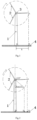
Fig. 1 is a front view of a windward rotation plane of wind turbine vanes; -
Fig. 2 is a schematic diagram of the optimal position for collecting sound signal of wind turbine vanes. - In the drawings: 1 represents the tower tube, 2 represents the vane, 3 represents the hub, and 4 represents the vertical projection of the windward rotation plane of the wind turbine vanes on the ground.
- Hereinafter, the appended drawings and detailed embodiments are used to explain the present invention in further detail, in an illustrative manner rather than in a limiting manner.
- As shown in
Fig. 1 and Fig. 2 , in this embodiment of the present invention, the optimal position for collecting sound signal of of wind turbine vanes is located within thevertical projection 4 of the windward rotation plane of the wind turbine vanes on the ground, which is the line segment of OB in the figure. The distance between the optimal position and the center point O of the tower tube is R×sinα, R is the rotation radius of the vane, and the rotation radius of the vane R = hub radius + vane length; When the sound pressure and sound pressure level intensity generated by normal operation of the wind turbine are the highest, the angle between the vane closest to the ground and the vertical axis of the tower tube is α, and α is generally 50°. B is the projection point of the maximum rotation radius of the vane. - The method for selecting the aforementioned optimal position for collecting sound signal of the wind turbine vanes provided in this embodiment comprises steps S1-S3.
- S1, selecting the main wind direction of the wind turbine, and determining the windward rotation plane of the vane of the wind turbine according to the main wind direction; wherein the vane usually rotates clockwise.
- S2, calculating the radius of the windward rotation plane of the vane of the wind turbine according to specification parameters of the wind turbine; wherein the specification parameters of the wind turbine comprise the radius of the
hub 3 and the length of thevane 2. - S3, measuring the sound pressure and sound pressure level intensity generated during normal operation of the wind turbine, and when the sound pressure and sound pressure level intensity are at maximum value, taking the projection point D of the tip of a
vane 2 within thevertical projection 4 of the windward rotation plane of the vane of the wind turbine on the ground to be the optimal position for collecting sound signal of the wind turbine vanes. As proved by experiments, when the vane of the wind turbine rotates clockwise to an included angle of 130° relative to the 12 o'clock direction, the generated sound pressure and sound pressure level intensity are the highest. At this time, the angle between thevane 2 closest to the ground and the vertical axis of thetower tube 1 is 50°. - When the direction of the incoming wind changes, the optimal position D changes accordingly, and the optimal position D is still located in the same plane as the rotation plane.
- In one embodiment of the present invention, according to the fluctuation range of the main wind direction in the same season, a number of sound signal collecting points for the wind turbine vanes are added. In the same season, the main wind direction may fluctuate in a small range. According to the fluctuation range, adding a number of sound signal collecting points for the wind turbine vanes can effectively improve the accuracy of signal collection.
- In one embodiment of the present invention, according to the change of the main wind directions in different seasons, a number of sound signal collecting points for the wind turbine vanes are added. In different seasons, due to the seasonal winds, each wind turbine unit in the wind farm is affected by the wind directions, and the vane rotation will have one or two main windward rotation planes. According to the change of the wind directions, adding a plurality of sound signal collecting points for the wind turbine vanes can effectively improve the accuracy of signal collection.
- It should be noted that the above is only a part of the implementation ways of the present invention, and any equivalent modification made to the system described according to the present invention is included in the scope of protection of the present invention. Those skilled in the art to which the present invention belongs can make substitutions to the described embodiments in a similar way, so long as it does not deviate from the structure of the present invention or exceed the scope defined by the claims, and these substitutions also belong to the scope of protection of the present invention.
Claims (8)
- An optimal position for collecting sound signal of wind turbine vanes, characterized in that, the optimal position is located within the vertical projection of the windward rotation plane of an vane of a wind turbine on the ground, and the distance between the optimal position and the center point of a tower tube (1) is R×sinα, where R is the rotation radius of the vane, and α is the included angle between a vane (2) closest to the ground and the vertical axis of the tower tube (1) when the sound pressure and sound pressure level intensity generated by normal operation of the wind turbine are the highest.
- The optimal position for collecting sound signal of wind turbine vanes according to claim 1, characterized in that α is 50°.
- A method for selecting the optimal position for collecting sound signal of wind turbine vanes according to claim 1 or 2, characterized in that the method comprises:S1: selecting a main wind direction of the wind turbine, and determining the windward rotation plane of the vane of the wind turbine according to the main wind direction;S2: calculating a radius of the windward rotation plane of the vane of the wind turbine according to specification parameters of the wind turbine;S3: measuring sound pressure and sound pressure level intensity generated during normal operation of the wind turbine, and when the sound pressure and sound pressure level intensity are at maximum values, taking the projection point of the tip of a vane (2) within the vertical projection (4) of the windward rotation plane of the vane of the wind turbine on the ground at this time to be the optimal position for collecting sound signal of the wind turbine vanes.
- The method for selecting the optimal position for collecting sound signal of wind turbine vanes according to claim 3, characterized in that, in S1, the rotation direction of the vane is clockwise against the wind.
- The method for selecting the optimal position for collecting sound signal of wind turbine vanes according to claim 3 or 4, characterized in that, in S2, the specification parameters of the wind turbine comprise the radius of a wind turbine hub (3) and the length of the vane (2).
- The method for selecting the optimal position for collecting sound signal of wind turbine vanes according to any one of claim 3 to 5, characterized in that, in S3, when the sound pressure and sound pressure level intensity are at maximum values, the included angle between the vane (2) closest to the ground and the vertical axis of the tower tube (1) is 50°.
- The method for selecting the optimal position for collecting sound signal of wind turbine vanes according to any one of claims 3 to 6, characterized in that, in S3, according to the fluctuation range of the main wind direction in the same season, a plurality of sound signal collecting points for the wind turbine vanes are added.
- The method for selecting the optimal position for collecting sound signal of wind turbine vanes according to any one of claims 3 to 7, characterized in that, in S3, a plurality of sound signal collecting points for the wind turbine vanes are added according to the change of main wind directions in different seasons.
Applications Claiming Priority (2)
| Application Number | Priority Date | Filing Date | Title |
|---|---|---|---|
| CN202111051210.XA CN113790129B (en) | 2021-09-08 | 2021-09-08 | Fan blade sound signal acquisition optimal position selection method |
| PCT/CN2022/098268 WO2023035708A1 (en) | 2021-09-08 | 2022-06-10 | Optimal position for wind turbine blade sound signal collection and selection method therefor |
Publications (3)
| Publication Number | Publication Date |
|---|---|
| EP4180658A1 true EP4180658A1 (en) | 2023-05-17 |
| EP4180658A4 EP4180658A4 (en) | 2024-03-06 |
| EP4180658B1 EP4180658B1 (en) | 2025-06-04 |
Family
ID=79182826
Family Applications (1)
| Application Number | Title | Priority Date | Filing Date |
|---|---|---|---|
| EP22851004.6A Active EP4180658B1 (en) | 2021-09-08 | 2022-06-10 | Optimal position for wind turbine blade sound signal collection and selection method therefor |
Country Status (3)
| Country | Link |
|---|---|
| EP (1) | EP4180658B1 (en) |
| CN (1) | CN113790129B (en) |
| WO (1) | WO2023035708A1 (en) |
Families Citing this family (1)
| Publication number | Priority date | Publication date | Assignee | Title |
|---|---|---|---|---|
| CN113790129B (en) * | 2021-09-08 | 2022-11-08 | 中国华能集团清洁能源技术研究院有限公司 | Fan blade sound signal acquisition optimal position selection method |
Family Cites Families (14)
| Publication number | Priority date | Publication date | Assignee | Title |
|---|---|---|---|---|
| US5471880A (en) * | 1994-04-28 | 1995-12-05 | Electric Power Research Institute | Method and apparatus for isolating and identifying periodic Doppler signals in a turbine |
| US8197207B2 (en) * | 2007-12-31 | 2012-06-12 | General Electric Company | Individual blade noise measurement system and method for wind turbines |
| JP5207074B2 (en) * | 2009-06-05 | 2013-06-12 | 清水建設株式会社 | Wind turbine blade abnormality determination method, abnormality determination device, and abnormality determination program |
| US9395337B2 (en) * | 2013-03-15 | 2016-07-19 | Digital Wind Systems, Inc. | Nondestructive acoustic doppler testing of wind turbine blades from the ground during operation |
| CN204704074U (en) * | 2015-05-22 | 2015-10-14 | 中能电力科技开发有限公司 | Wind power generation unit blade noise detection apparatus |
| CN109322797A (en) * | 2017-07-31 | 2019-02-12 | 上海绿孚科技有限公司 | The blade state monitoring system and detection method of wind power generating set based on acoustic processing |
| CN207195098U (en) * | 2017-07-31 | 2018-04-06 | 上海绿孚科技有限公司 | A kind of blade state monitoring system of the wind power generating set based on acoustic processing |
| US20210055266A1 (en) * | 2018-04-26 | 2021-02-25 | Ping Services Pty Ltd | An Apparatus and Method of Detecting Anomalies in an Acoustic Signal |
| CN111120223B (en) * | 2019-12-16 | 2021-09-03 | 大连赛听科技有限公司 | Blade fault monitoring method and device based on double arrays |
| CN113090471B (en) * | 2019-12-23 | 2022-10-14 | 新疆金风科技股份有限公司 | Tower clearance audio monitoring system, method and device of wind generating set |
| CN111287913A (en) * | 2020-03-24 | 2020-06-16 | 内蒙古工业大学 | A noise test device for wind turbine blades based on a rotating platform |
| CN212454697U (en) * | 2020-07-02 | 2021-02-02 | 中国船舶重工集团海装风电股份有限公司 | A wind turbine blade operating state detection device |
| CN112324629B (en) * | 2020-11-09 | 2024-12-03 | 华能陕西靖边电力有限公司 | A wind turbine blade early damage monitoring system and method based on vibration and sound |
| CN113790129B (en) * | 2021-09-08 | 2022-11-08 | 中国华能集团清洁能源技术研究院有限公司 | Fan blade sound signal acquisition optimal position selection method |
-
2021
- 2021-09-08 CN CN202111051210.XA patent/CN113790129B/en active Active
-
2022
- 2022-06-10 EP EP22851004.6A patent/EP4180658B1/en active Active
- 2022-06-10 WO PCT/CN2022/098268 patent/WO2023035708A1/en not_active Ceased
Also Published As
| Publication number | Publication date |
|---|---|
| CN113790129B (en) | 2022-11-08 |
| CN113790129A (en) | 2021-12-14 |
| WO2023035708A1 (en) | 2023-03-16 |
| EP4180658B1 (en) | 2025-06-04 |
| EP4180658A4 (en) | 2024-03-06 |
Similar Documents
| Publication | Publication Date | Title |
|---|---|---|
| CN109812390B (en) | Blade clearance monitoring method of wind generating set | |
| AU2019478946B2 (en) | Method and system for monitoring health state of blade root fastener | |
| KR102847924B1 (en) | Wind turbine blade clearance monitoring device and method and wind turbine | |
| AU2014200423B2 (en) | Method and apparatus for wind turbine noise reduction | |
| CN110005581A (en) | A monitoring and control method for wind turbine blade and tower clearance | |
| WO2021159919A1 (en) | System and method for monitoring health state of offshore wind power wind turbine and sound waves of sea waves | |
| CN101813055A (en) | Wind driven generator with blade-tip deflection detection | |
| CN112380699A (en) | Wind turbine generator yaw error early warning analysis method based on multidimensional analysis | |
| CN212454697U (en) | A wind turbine blade operating state detection device | |
| CN208686524U (en) | A kind of wind power generating set thunder and lightning on-line monitoring equipment | |
| EP4180658B1 (en) | Optimal position for wind turbine blade sound signal collection and selection method therefor | |
| CN117780573A (en) | Multi-data-fusion real-time monitoring method for impeller unbalance of wind turbine generator | |
| CN115855465A (en) | A wind turbine blade condition monitoring system and method based on reverberation noise | |
| CN118601811A (en) | A wind turbine tower state monitoring system and method | |
| CN219081774U (en) | Wind turbine blade state monitoring system | |
| CN113464379B (en) | Floating type offshore wind turbine running state monitoring method | |
| EP4542029A1 (en) | Computer implemented method and computing system for monitoring the blades of a wind turbine | |
| CN111120223B (en) | Blade fault monitoring method and device based on double arrays | |
| CN114396364B (en) | A large-scale safety monitoring system and method for wind turbine blades | |
| CN115434877B (en) | Blade internal state detection method and device | |
| CN117150707A (en) | A method and system for calculating the lightning strike probability distribution of multiple air-termination blades of a rotating wind turbine | |
| CN217176802U (en) | Wind-powered electricity generation blade large-scale safety monitoring system | |
| CN117552936A (en) | A wind turbine blade condition monitoring system and method | |
| CN116498501A (en) | A safety risk early warning method for blade sweeping of large megawatt wind turbines | |
| CN222894335U (en) | A lightning online monitoring system for wind turbines |
Legal Events
| Date | Code | Title | Description |
|---|---|---|---|
| STAA | Information on the status of an ep patent application or granted ep patent |
Free format text: STATUS: UNKNOWN |
|
| STAA | Information on the status of an ep patent application or granted ep patent |
Free format text: STATUS: THE INTERNATIONAL PUBLICATION HAS BEEN MADE |
|
| PUAI | Public reference made under article 153(3) epc to a published international application that has entered the european phase |
Free format text: ORIGINAL CODE: 0009012 |
|
| STAA | Information on the status of an ep patent application or granted ep patent |
Free format text: STATUS: REQUEST FOR EXAMINATION WAS MADE |
|
| 17P | Request for examination filed |
Effective date: 20230209 |
|
| AK | Designated contracting states |
Kind code of ref document: A1 Designated state(s): AL AT BE BG CH CY CZ DE DK EE ES FI FR GB GR HR HU IE IS IT LI LT LU LV MC MK MT NL NO PL PT RO RS SE SI SK SM TR |
|
| A4 | Supplementary search report drawn up and despatched |
Effective date: 20240201 |
|
| RIC1 | Information provided on ipc code assigned before grant |
Ipc: F03D 17/00 20160101AFI20240126BHEP |
|
| DAV | Request for validation of the european patent (deleted) | ||
| DAX | Request for extension of the european patent (deleted) | ||
| GRAP | Despatch of communication of intention to grant a patent |
Free format text: ORIGINAL CODE: EPIDOSNIGR1 |
|
| STAA | Information on the status of an ep patent application or granted ep patent |
Free format text: STATUS: GRANT OF PATENT IS INTENDED |
|
| INTG | Intention to grant announced |
Effective date: 20250102 |
|
| GRAS | Grant fee paid |
Free format text: ORIGINAL CODE: EPIDOSNIGR3 |
|
| GRAA | (expected) grant |
Free format text: ORIGINAL CODE: 0009210 |
|
| STAA | Information on the status of an ep patent application or granted ep patent |
Free format text: STATUS: THE PATENT HAS BEEN GRANTED |
|
| AK | Designated contracting states |
Kind code of ref document: B1 Designated state(s): AL AT BE BG CH CY CZ DE DK EE ES FI FR GB GR HR HU IE IS IT LI LT LU LV MC MK MT NL NO PL PT RO RS SE SI SK SM TR |
|
| REG | Reference to a national code |
Ref country code: GB Ref legal event code: FG4D |
|
| REG | Reference to a national code |
Ref country code: CH Ref legal event code: EP |
|
| REG | Reference to a national code |
Ref country code: DE Ref legal event code: R096 Ref document number: 602022015657 Country of ref document: DE |
|
| REG | Reference to a national code |
Ref country code: IE Ref legal event code: FG4D |
|
| PGFP | Annual fee paid to national office [announced via postgrant information from national office to epo] |
Ref country code: FR Payment date: 20250630 Year of fee payment: 4 |
|
| PGFP | Annual fee paid to national office [announced via postgrant information from national office to epo] |
Ref country code: AT Payment date: 20250721 Year of fee payment: 4 |
|
| REG | Reference to a national code |
Ref country code: NL Ref legal event code: MP Effective date: 20250604 |
|
| PG25 | Lapsed in a contracting state [announced via postgrant information from national office to epo] |
Ref country code: ES Free format text: LAPSE BECAUSE OF FAILURE TO SUBMIT A TRANSLATION OF THE DESCRIPTION OR TO PAY THE FEE WITHIN THE PRESCRIBED TIME-LIMIT Effective date: 20250604 Ref country code: FI Free format text: LAPSE BECAUSE OF FAILURE TO SUBMIT A TRANSLATION OF THE DESCRIPTION OR TO PAY THE FEE WITHIN THE PRESCRIBED TIME-LIMIT Effective date: 20250604 |
|
| PGFP | Annual fee paid to national office [announced via postgrant information from national office to epo] |
Ref country code: DE Payment date: 20250711 Year of fee payment: 4 |
|
| REG | Reference to a national code |
Ref country code: LT Ref legal event code: MG9D |
|
| PG25 | Lapsed in a contracting state [announced via postgrant information from national office to epo] |
Ref country code: GR Free format text: LAPSE BECAUSE OF FAILURE TO SUBMIT A TRANSLATION OF THE DESCRIPTION OR TO PAY THE FEE WITHIN THE PRESCRIBED TIME-LIMIT Effective date: 20250905 Ref country code: NO Free format text: LAPSE BECAUSE OF FAILURE TO SUBMIT A TRANSLATION OF THE DESCRIPTION OR TO PAY THE FEE WITHIN THE PRESCRIBED TIME-LIMIT Effective date: 20250904 |
|
| PG25 | Lapsed in a contracting state [announced via postgrant information from national office to epo] |
Ref country code: PL Free format text: LAPSE BECAUSE OF FAILURE TO SUBMIT A TRANSLATION OF THE DESCRIPTION OR TO PAY THE FEE WITHIN THE PRESCRIBED TIME-LIMIT Effective date: 20250604 |
|
| PG25 | Lapsed in a contracting state [announced via postgrant information from national office to epo] |
Ref country code: BG Free format text: LAPSE BECAUSE OF FAILURE TO SUBMIT A TRANSLATION OF THE DESCRIPTION OR TO PAY THE FEE WITHIN THE PRESCRIBED TIME-LIMIT Effective date: 20250604 |
|
| PG25 | Lapsed in a contracting state [announced via postgrant information from national office to epo] |
Ref country code: HR Free format text: LAPSE BECAUSE OF FAILURE TO SUBMIT A TRANSLATION OF THE DESCRIPTION OR TO PAY THE FEE WITHIN THE PRESCRIBED TIME-LIMIT Effective date: 20250604 |
|
| PG25 | Lapsed in a contracting state [announced via postgrant information from national office to epo] |
Ref country code: RS Free format text: LAPSE BECAUSE OF FAILURE TO SUBMIT A TRANSLATION OF THE DESCRIPTION OR TO PAY THE FEE WITHIN THE PRESCRIBED TIME-LIMIT Effective date: 20250904 |
|
| PG25 | Lapsed in a contracting state [announced via postgrant information from national office to epo] |
Ref country code: LV Free format text: LAPSE BECAUSE OF FAILURE TO SUBMIT A TRANSLATION OF THE DESCRIPTION OR TO PAY THE FEE WITHIN THE PRESCRIBED TIME-LIMIT Effective date: 20250604 |
|
| PG25 | Lapsed in a contracting state [announced via postgrant information from national office to epo] |
Ref country code: NL Free format text: LAPSE BECAUSE OF FAILURE TO SUBMIT A TRANSLATION OF THE DESCRIPTION OR TO PAY THE FEE WITHIN THE PRESCRIBED TIME-LIMIT Effective date: 20250604 |
|
| PG25 | Lapsed in a contracting state [announced via postgrant information from national office to epo] |
Ref country code: PT Free format text: LAPSE BECAUSE OF FAILURE TO SUBMIT A TRANSLATION OF THE DESCRIPTION OR TO PAY THE FEE WITHIN THE PRESCRIBED TIME-LIMIT Effective date: 20251006 |
|
| REG | Reference to a national code |
Ref country code: AT Ref legal event code: MK05 Ref document number: 1800550 Country of ref document: AT Kind code of ref document: T Effective date: 20250604 |
|
| PG25 | Lapsed in a contracting state [announced via postgrant information from national office to epo] |
Ref country code: IS Free format text: LAPSE BECAUSE OF FAILURE TO SUBMIT A TRANSLATION OF THE DESCRIPTION OR TO PAY THE FEE WITHIN THE PRESCRIBED TIME-LIMIT Effective date: 20251004 |
|
| PG25 | Lapsed in a contracting state [announced via postgrant information from national office to epo] |
Ref country code: AT Free format text: LAPSE BECAUSE OF FAILURE TO SUBMIT A TRANSLATION OF THE DESCRIPTION OR TO PAY THE FEE WITHIN THE PRESCRIBED TIME-LIMIT Effective date: 20250604 Ref country code: SM Free format text: LAPSE BECAUSE OF FAILURE TO SUBMIT A TRANSLATION OF THE DESCRIPTION OR TO PAY THE FEE WITHIN THE PRESCRIBED TIME-LIMIT Effective date: 20250604 |
|
| PG25 | Lapsed in a contracting state [announced via postgrant information from national office to epo] |
Ref country code: CZ Free format text: LAPSE BECAUSE OF FAILURE TO SUBMIT A TRANSLATION OF THE DESCRIPTION OR TO PAY THE FEE WITHIN THE PRESCRIBED TIME-LIMIT Effective date: 20250604 |
|
| PG25 | Lapsed in a contracting state [announced via postgrant information from national office to epo] |
Ref country code: EE Free format text: LAPSE BECAUSE OF FAILURE TO SUBMIT A TRANSLATION OF THE DESCRIPTION OR TO PAY THE FEE WITHIN THE PRESCRIBED TIME-LIMIT Effective date: 20250604 |
|
| PG25 | Lapsed in a contracting state [announced via postgrant information from national office to epo] |
Ref country code: SK Free format text: LAPSE BECAUSE OF FAILURE TO SUBMIT A TRANSLATION OF THE DESCRIPTION OR TO PAY THE FEE WITHIN THE PRESCRIBED TIME-LIMIT Effective date: 20250604 |
|
| REG | Reference to a national code |
Ref country code: CH Ref legal event code: H13 Free format text: ST27 STATUS EVENT CODE: U-0-0-H10-H13 (AS PROVIDED BY THE NATIONAL OFFICE) Effective date: 20260127 |
|
| PG25 | Lapsed in a contracting state [announced via postgrant information from national office to epo] |
Ref country code: IT Free format text: LAPSE BECAUSE OF FAILURE TO SUBMIT A TRANSLATION OF THE DESCRIPTION OR TO PAY THE FEE WITHIN THE PRESCRIBED TIME-LIMIT Effective date: 20250604 |
|
| PG25 | Lapsed in a contracting state [announced via postgrant information from national office to epo] |
Ref country code: LU Free format text: LAPSE BECAUSE OF NON-PAYMENT OF DUE FEES Effective date: 20250610 |
|
| REG | Reference to a national code |
Ref country code: BE Ref legal event code: MM Effective date: 20250630 |
|
| REG | Reference to a national code |
Ref country code: DE Ref legal event code: R097 Ref document number: 602022015657 Country of ref document: DE |
|
| PG25 | Lapsed in a contracting state [announced via postgrant information from national office to epo] |
Ref country code: RO Free format text: LAPSE BECAUSE OF FAILURE TO SUBMIT A TRANSLATION OF THE DESCRIPTION OR TO PAY THE FEE WITHIN THE PRESCRIBED TIME-LIMIT Effective date: 20250604 |
|
| PG25 | Lapsed in a contracting state [announced via postgrant information from national office to epo] |
Ref country code: MC Free format text: LAPSE BECAUSE OF FAILURE TO SUBMIT A TRANSLATION OF THE DESCRIPTION OR TO PAY THE FEE WITHIN THE PRESCRIBED TIME-LIMIT Effective date: 20250604 |
|
| PLBE | No opposition filed within time limit |
Free format text: ORIGINAL CODE: 0009261 |
|
| STAA | Information on the status of an ep patent application or granted ep patent |
Free format text: STATUS: NO OPPOSITION FILED WITHIN TIME LIMIT |
|
| PG25 | Lapsed in a contracting state [announced via postgrant information from national office to epo] |
Ref country code: IE Free format text: LAPSE BECAUSE OF NON-PAYMENT OF DUE FEES Effective date: 20250610 Ref country code: DK Free format text: LAPSE BECAUSE OF FAILURE TO SUBMIT A TRANSLATION OF THE DESCRIPTION OR TO PAY THE FEE WITHIN THE PRESCRIBED TIME-LIMIT Effective date: 20250604 |
|
| PG25 | Lapsed in a contracting state [announced via postgrant information from national office to epo] |
Ref country code: BE Free format text: LAPSE BECAUSE OF NON-PAYMENT OF DUE FEES Effective date: 20250630 |
|
| REG | Reference to a national code |
Ref country code: CH Ref legal event code: L10 Free format text: ST27 STATUS EVENT CODE: U-0-0-L10-L00 (AS PROVIDED BY THE NATIONAL OFFICE) Effective date: 20260416 |
|
| PG25 | Lapsed in a contracting state [announced via postgrant information from national office to epo] |
Ref country code: CH Free format text: LAPSE BECAUSE OF NON-PAYMENT OF DUE FEES Effective date: 20250630 |
|
| 26N | No opposition filed |
Effective date: 20260305 |