EP4180626A1 - Turbomachine blade trailing edge cooling circuit with turn passage having set of obstructions - Google Patents
Turbomachine blade trailing edge cooling circuit with turn passage having set of obstructions Download PDFInfo
- Publication number
- EP4180626A1 EP4180626A1 EP22192282.6A EP22192282A EP4180626A1 EP 4180626 A1 EP4180626 A1 EP 4180626A1 EP 22192282 A EP22192282 A EP 22192282A EP 4180626 A1 EP4180626 A1 EP 4180626A1
- Authority
- EP
- European Patent Office
- Prior art keywords
- passage
- trailing edge
- airfoil body
- radially extending
- cooling circuit
- Prior art date
- Legal status (The legal status is an assumption and is not a legal conclusion. Google has not performed a legal analysis and makes no representation as to the accuracy of the status listed.)
- Granted
Links
Images






Classifications
-
- F—MECHANICAL ENGINEERING; LIGHTING; HEATING; WEAPONS; BLASTING
- F01—MACHINES OR ENGINES IN GENERAL; ENGINE PLANTS IN GENERAL; STEAM ENGINES
- F01D—NON-POSITIVE DISPLACEMENT MACHINES OR ENGINES, e.g. STEAM TURBINES
- F01D5/00—Blades; Blade-carrying members; Heating, heat-insulating, cooling or antivibration means on the blades or the members
- F01D5/12—Blades
- F01D5/14—Form or construction
- F01D5/18—Hollow blades, i.e. blades with cooling or heating channels or cavities; Heating, heat-insulating or cooling means on blades
- F01D5/187—Convection cooling
-
- F—MECHANICAL ENGINEERING; LIGHTING; HEATING; WEAPONS; BLASTING
- F01—MACHINES OR ENGINES IN GENERAL; ENGINE PLANTS IN GENERAL; STEAM ENGINES
- F01D—NON-POSITIVE DISPLACEMENT MACHINES OR ENGINES, e.g. STEAM TURBINES
- F01D5/00—Blades; Blade-carrying members; Heating, heat-insulating, cooling or antivibration means on the blades or the members
- F01D5/12—Blades
- F01D5/14—Form or construction
- F01D5/18—Hollow blades, i.e. blades with cooling or heating channels or cavities; Heating, heat-insulating or cooling means on blades
- F01D5/186—Film cooling
-
- F—MECHANICAL ENGINEERING; LIGHTING; HEATING; WEAPONS; BLASTING
- F01—MACHINES OR ENGINES IN GENERAL; ENGINE PLANTS IN GENERAL; STEAM ENGINES
- F01D—NON-POSITIVE DISPLACEMENT MACHINES OR ENGINES, e.g. STEAM TURBINES
- F01D25/00—Component parts, details, or accessories, not provided for in, or of interest apart from, other groups
- F01D25/08—Cooling; Heating; Heat-insulation
- F01D25/12—Cooling
-
- F—MECHANICAL ENGINEERING; LIGHTING; HEATING; WEAPONS; BLASTING
- F01—MACHINES OR ENGINES IN GENERAL; ENGINE PLANTS IN GENERAL; STEAM ENGINES
- F01D—NON-POSITIVE DISPLACEMENT MACHINES OR ENGINES, e.g. STEAM TURBINES
- F01D5/00—Blades; Blade-carrying members; Heating, heat-insulating, cooling or antivibration means on the blades or the members
- F01D5/12—Blades
- F01D5/14—Form or construction
- F01D5/147—Construction, i.e. structural features, e.g. of weight-saving hollow blades
-
- F—MECHANICAL ENGINEERING; LIGHTING; HEATING; WEAPONS; BLASTING
- F01—MACHINES OR ENGINES IN GENERAL; ENGINE PLANTS IN GENERAL; STEAM ENGINES
- F01D—NON-POSITIVE DISPLACEMENT MACHINES OR ENGINES, e.g. STEAM TURBINES
- F01D5/00—Blades; Blade-carrying members; Heating, heat-insulating, cooling or antivibration means on the blades or the members
- F01D5/12—Blades
- F01D5/14—Form or construction
- F01D5/18—Hollow blades, i.e. blades with cooling or heating channels or cavities; Heating, heat-insulating or cooling means on blades
-
- F—MECHANICAL ENGINEERING; LIGHTING; HEATING; WEAPONS; BLASTING
- F01—MACHINES OR ENGINES IN GENERAL; ENGINE PLANTS IN GENERAL; STEAM ENGINES
- F01D—NON-POSITIVE DISPLACEMENT MACHINES OR ENGINES, e.g. STEAM TURBINES
- F01D9/00—Stators
- F01D9/02—Nozzles; Nozzle boxes; Stator blades; Guide conduits, e.g. individual nozzles
-
- F—MECHANICAL ENGINEERING; LIGHTING; HEATING; WEAPONS; BLASTING
- F05—INDEXING SCHEMES RELATING TO ENGINES OR PUMPS IN VARIOUS SUBCLASSES OF CLASSES F01-F04
- F05B—INDEXING SCHEME RELATING TO WIND, SPRING, WEIGHT, INERTIA OR LIKE MOTORS, TO MACHINES OR ENGINES FOR LIQUIDS COVERED BY SUBCLASSES F03B, F03D AND F03G
- F05B2260/00—Function
- F05B2260/20—Heat transfer, e.g. cooling
- F05B2260/221—Improvement of heat transfer
-
- F—MECHANICAL ENGINEERING; LIGHTING; HEATING; WEAPONS; BLASTING
- F05—INDEXING SCHEMES RELATING TO ENGINES OR PUMPS IN VARIOUS SUBCLASSES OF CLASSES F01-F04
- F05D—INDEXING SCHEME FOR ASPECTS RELATING TO NON-POSITIVE-DISPLACEMENT MACHINES OR ENGINES, GAS-TURBINES OR JET-PROPULSION PLANTS
- F05D2240/00—Components
- F05D2240/20—Rotors
- F05D2240/30—Characteristics of rotor blades, i.e. of any element transforming dynamic fluid energy to or from rotational energy and being attached to a rotor
- F05D2240/304—Characteristics of rotor blades, i.e. of any element transforming dynamic fluid energy to or from rotational energy and being attached to a rotor related to the trailing edge of a rotor blade
-
- F—MECHANICAL ENGINEERING; LIGHTING; HEATING; WEAPONS; BLASTING
- F05—INDEXING SCHEMES RELATING TO ENGINES OR PUMPS IN VARIOUS SUBCLASSES OF CLASSES F01-F04
- F05D—INDEXING SCHEME FOR ASPECTS RELATING TO NON-POSITIVE-DISPLACEMENT MACHINES OR ENGINES, GAS-TURBINES OR JET-PROPULSION PLANTS
- F05D2250/00—Geometry
- F05D2250/10—Two-dimensional
- F05D2250/18—Two-dimensional patterned
- F05D2250/185—Two-dimensional patterned serpentine-like
-
- F—MECHANICAL ENGINEERING; LIGHTING; HEATING; WEAPONS; BLASTING
- F05—INDEXING SCHEMES RELATING TO ENGINES OR PUMPS IN VARIOUS SUBCLASSES OF CLASSES F01-F04
- F05D—INDEXING SCHEME FOR ASPECTS RELATING TO NON-POSITIVE-DISPLACEMENT MACHINES OR ENGINES, GAS-TURBINES OR JET-PROPULSION PLANTS
- F05D2260/00—Function
- F05D2260/20—Heat transfer, e.g. cooling
- F05D2260/202—Heat transfer, e.g. cooling by film cooling
-
- F—MECHANICAL ENGINEERING; LIGHTING; HEATING; WEAPONS; BLASTING
- F05—INDEXING SCHEMES RELATING TO ENGINES OR PUMPS IN VARIOUS SUBCLASSES OF CLASSES F01-F04
- F05D—INDEXING SCHEME FOR ASPECTS RELATING TO NON-POSITIVE-DISPLACEMENT MACHINES OR ENGINES, GAS-TURBINES OR JET-PROPULSION PLANTS
- F05D2260/00—Function
- F05D2260/20—Heat transfer, e.g. cooling
- F05D2260/221—Improvement of heat transfer
- F05D2260/2212—Improvement of heat transfer by creating turbulence
-
- F—MECHANICAL ENGINEERING; LIGHTING; HEATING; WEAPONS; BLASTING
- F05—INDEXING SCHEMES RELATING TO ENGINES OR PUMPS IN VARIOUS SUBCLASSES OF CLASSES F01-F04
- F05D—INDEXING SCHEME FOR ASPECTS RELATING TO NON-POSITIVE-DISPLACEMENT MACHINES OR ENGINES, GAS-TURBINES OR JET-PROPULSION PLANTS
- F05D2260/00—Function
- F05D2260/20—Heat transfer, e.g. cooling
- F05D2260/232—Heat transfer, e.g. cooling characterized by the cooling medium
-
- F—MECHANICAL ENGINEERING; LIGHTING; HEATING; WEAPONS; BLASTING
- F05—INDEXING SCHEMES RELATING TO ENGINES OR PUMPS IN VARIOUS SUBCLASSES OF CLASSES F01-F04
- F05D—INDEXING SCHEME FOR ASPECTS RELATING TO NON-POSITIVE-DISPLACEMENT MACHINES OR ENGINES, GAS-TURBINES OR JET-PROPULSION PLANTS
- F05D2260/00—Function
- F05D2260/60—Fluid transfer
- F05D2260/608—Aeration, ventilation, dehumidification or moisture removal of closed spaces
Definitions
- the disclosure relates generally to turbomachine blades and, more particularly, to a turbomachine blade having a trailing edge cooling circuit with a turn passage having a set of obstructions therein.
- Turbomachine blades such as rotor blades or stationary vanes, include airfoils that accelerate flow through contraction of area and the introduction of tangential velocity.
- the trailing edges of the airfoils are difficult to cool due to the small volume of material compared to the large heat loads at that location. Notably, the mismatch between external surface area and the internal surface makes any cooling solution challenging.
- trailing edges are typically cooled with coolant flows having high flow rates.
- the high flow rates to the trailing edges decreases the coolant that can be used elsewhere.
- the high flow rates also require the trailing edges to have minimum thicknesses to accommodate the passages that deliver the coolant flow and create the necessary cold-to-hot area ratio. The minimum thicknesses do not allow for sharper trailing edges that would improve aerodynamic performance.
- An aspect of the disclosure provides a turbomachine blade, comprising: an airfoil body having a pressure side and a suction side connected by a leading edge and a trailing edge; a coolant feed passage defined in the airfoil body; a first coolant reuse passage defined in the airfoil body; a first cooling circuit defined in the airfoil body, the first cooling circuit including: a first rearward passage extending toward the trailing edge from and fluidly coupled to the coolant feed passage; a first radially spreading return passage extending away from the trailing edge toward and fluidly coupled to the first coolant reuse passage; and a first radially extending turn passage coupling the first rearward passage and the first radially spreading return passage; and a first set of obstructions positioned in the first radially extending turn passage.
- Another aspect of the disclosure includes any of the preceding aspects, and further comprises a plurality of vent passages extending from the first radially extending turn passage through the trailing edge of the airfoil body.
- Another aspect of the disclosure includes any of the preceding aspects, and the first rearward passage is radially offset from the first radially spreading return passage along a radial axis of the airfoil body.
- Another aspect of the disclosure includes any of the preceding aspects, and further comprises a second set of obstructions positioned in the first radially spreading return passage.
- Another aspect of the disclosure includes any of the preceding aspects, and further comprises: a second cooling circuit defined in the airfoil body, the second cooling circuit including: a second rearward passage extending toward the trailing edge from and fluidly coupled to the coolant feed passage; a second radially spreading return passage extending away from the trailing edge toward and fluidly coupled to a second coolant reuse passage defined in the airfoil body; and a second radially extending turn passage coupling the second rearward passage and the second radially spreading return passage; wherein the second rearward passage is radially offset from the second radially spreading return passage along the radial axis of the airfoil body.
- Another aspect of the disclosure includes any of the preceding aspects, and the first cooling circuit is circumferentially offset from the second cooling circuit in the airfoil body.
- Another aspect of the disclosure includes any of the preceding aspects, and further comprises a second set of obstructions positioned in the second radially spreading return passage.
- Another aspect of the disclosure includes any of the preceding aspects, and further comprises a plurality of the first cooling circuits radially spaced in the airfoil body, and a plurality of second cooling circuits radially spaced in the airfoil body.
- Another aspect of the disclosure includes any of the preceding aspects, and the trailing edge has an ellipse ratio between 1.1 and 4.
- Another aspect of the disclosure includes any of the preceding aspects, and the first cooling circuit is adjacent the suction side of the airfoil body, and the second cooling circuit is adjacent the pressure side of the airfoil body.
- first radially extending turn passage has a first circumferential width at a forward end thereof that is greater than a second circumferential width at an aft end thereof.
- An aspect of the disclosure provides a coupon for replacing a cutout of a predetermined area in an airfoil body of a turbomachine blade, the airfoil body having a pressure side and a suction side connected by a leading edge and a trailing edge, the cutout within the trailing edge of the airfoil body, the coupon comprising: a coupon body; a first cooling circuit defined in the coupon body, the first cooling circuit including: a first rearward passage extending toward the trailing edge from and fluidly coupled to a coolant feed passage defined in at least one of the coupon body and the airfoil body; a first radially spreading return passage extending away from the trailing edge toward and fluidly coupled to a first coolant reuse passage defined in at least one of the coupon body and the airfoil body; a first radially extending turn passage coupling the first rearward passage and the first radially spreading return passage; and a first set of obstructions positioned in the first radially extending turn passage.
- Another aspect of the disclosure includes any of the preceding aspects, and further comprises a plurality of vent passages extending from the first radially extending turn passage through the trailing edge of the coupon body.
- Another aspect of the disclosure includes any of the preceding aspects, and the first rearward passage is radially offset from the first radially spreading return passage along a radial axis of the airfoil body.
- Another aspect of the disclosure includes any of the preceding aspects, and further comprises a second set of obstructions positioned in the first radially spreading return passage.
- Another aspect of the disclosure includes any of the preceding aspects, and further comprises: a second cooling circuit defined in the coupon body, the second cooling circuit including: a second rearward passage extending toward the trailing edge from and fluidly coupled to the coolant feed passage; a second radially spreading return passage extending away from the trailing edge toward and fluidly coupled to a second coolant reuse passage defined in at least one of the coupon body and the airfoil body; and a second radially extending turn passage coupling the second rearward passage and the second radially spreading return passage, wherein the second rearward passage is radially offset from the second radially spreading return passage along the radial axis of the airfoil body.
- Another aspect of the disclosure includes any of the preceding aspects, and the trailing edge has an ellipse ratio between 1.1 and 4.
- first radially extending turn passage has a first circumferential width at a forward end thereof that is greater than a second circumferential width at an aft end thereof.
- An aspect of the disclosure provides a gas turbine system, comprising: a compressor; a combustor; and a turbine, the turbine including a turbomachine blade including a trailing edge cooling system, the turbomachine blade including: an airfoil body having a pressure side and a suction side connected by a leading edge and a trailing edge; a coolant feed passage defined in the airfoil body; a first coolant reuse passage defined in the airfoil body; a first cooling circuit defined in the airfoil body, the first cooling circuit including: a first rearward passage extending toward the trailing edge from and fluidly coupled to the coolant feed passage; a first radially spreading return passage extending away from the trailing edge toward and fluidly coupled to the first coolant reuse passage; and a first radially extending turn passage coupling the first rearward passage and the first radially spreading return passage; and a first set of obstructions positioned in the first radially extending turn passage.
- downstream and upstream are terms that indicate a direction relative to the flow of a fluid, such as the working fluid through the turbine engine or, for example, the flow of air through the combustor or coolant through one of the turbine's component systems.
- the term “downstream” corresponds to the direction of flow of the fluid, and the term “upstream” refers to the direction opposite to the flow (i.e., the direction from which the flow originates).
- forward and aft refer to directions, with “forward” referring to the front or compressor end of the engine, and “aft” referring to the rearward section of the turbomachine.
- forward refers to the leading edge of a turbomachine blade
- aft or “rear” refers to the trailing edge of a turbomachine blade.
- radial refers to movement or position perpendicular to an axis. For example, if a first component resides closer to the axis than a second component, it will be stated herein that the first component is “radially inward” or “inboard” of the second component. If, on the other hand, the first component resides further from the axis than the second component, it may be stated herein that the first component is “radially outward” or “outboard” of the second component.
- axial refers to movement or position parallel to the axis of rotation of the turbine system, or in a chordal direction between leading and trailing edges of an airfoil.
- circumferential refers to movement or position around an axis. It will be appreciated that such terms may be applied in relation to the center axis of the turbine.
- an axial orientation is referenced with an "A”
- a radial orientation is referenced with an “R”
- a circumferential orientation (about axis A) is referenced with a "C”.
- the turbomachine blade may include an airfoil body having a pressure side and a suction side connected by a leading edge and a trailing edge, a coolant feed passage defined in the airfoil body, and a coolant reuse (collection) passage defined in the airfoil body.
- the blade may also include a first cooling circuit defined in the airfoil body.
- the first cooling circuit may include a rearward passage extending toward the trailing edge from and fluidly coupled to the coolant feed passage, and a radially spreading return passage extending away from the trailing edge toward and fluidly coupled to the coolant reuse passage.
- the first cooling circuit may also include a radially extending turn passage coupling the rearward passage and the radially spreading return passage.
- a first set of obstructions may be positioned in the radially extending turn passage.
- the obstructions created through additive manufacturing, have a density that allows a lower coolant flow rate and creates sufficient back pressure to allow some of the coolant to exit through vent openings in the trailing edge.
- the obstructions in the turn passage also provide additional structural strength and allow the trailing edge to have a sharper turn and use thinner walls, thus improving aerodynamic performance of the blade. Coolant not exiting through the vent openings can be reused, for example, for film cooling an exterior surface of the airfoil body or for other purposes.
- a second cooling circuit may also be provided, e.g., on a pressure side of the airfoil body, to shield parts of the first cooling circuit from a heat load, thus improving the effectiveness of coolant in the first cooling circuit.
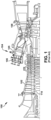
- FIG. 1 shows a schematic illustration of an illustrative turbomachine 100 in the form of a combustion or gas turbine system.
- Turbomachine 100 includes a compressor 102 and a combustor 104.
- Combustor 104 includes a combustion region 105 and a fuel nozzle assembly 106.
- Turbomachine 100 also includes a turbine 108 and a common compressor/turbine shaft 110 (sometimes referred to as rotor 110).
- the combustion turbine system is a 7HA or 9HA engine, commercially available from General Electric Company, Greenville, S.C.
- the present disclosure is not limited to any one particular GT system and may be implemented in connection with other engines including, for example, the other HA, F, B, LM, GT, TM and E-class engine models of General Electric Company and engine models of other companies. Further, the teachings of the disclosure are not necessarily applicable to only a GT system and may be applied to other types of turbomachines, e.g., steam turbines, jet engines, compressors, etc.
- FIG. 2 shows a cross-sectional view of an illustrative turbine 108 of turbomachine 100 ( FIG. 2 ) with three turbine stages that may be used with the gas turbine system in FIG. 2 .
- Each turbine stage of turbine 108 includes a row of stationary blades 112 coupled to a stationary casing of turbomachine 100 and positioned axially adjacent a rotating row of blades 114.
- Row of blades 112 includes stationary blades or nozzles 116 (vanes).
- Each nozzle 116 may be held in turbine assembly 108 by a radially outer platform 118 and a radially inner platform 120.
- Row of rotating blades 114 in turbine 108 includes rotating blades 122 coupled to rotor 110 and rotating with the rotor 110.
- Rotating blades 122 include a radially inward platform 124 (at root of blade) coupled to rotor 110 and, optionally, may include a radially outward tip shroud 126 (at tip of blade).
- blade shall refer collectively to stationary blades for vanes or nozzles 116 and rotating blades 122, unless otherwise stated.
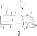
- FIG. 3 is a perspective view of a blade 130 in the form of a turbine rotor blade 122 of the type in which embodiments of the present disclosure may be employed.
- Blade 130 includes a root 132 by which blade 130 attaches to rotor 110 ( FIG. 2 ).
- Root 132 may include a dovetail configured for mounting in a corresponding dovetail slot in the perimeter of the rotor disc.
- Root 132 may further include a shank that extends between the dovetail and a platform 134, which is disposed at the junction of an airfoil body 136 and root 132 and defines a portion of the inboard boundary of the flow path through turbine 108.
- airfoil body 136 is the active component of rotor blade 130 that intercepts the flow of working fluid and induces the rotor disc to rotate.
- Airfoil body 136 of blade 130 includes a pressure side 140, i.e., a concave pressure side (PS) outer wall, and a circumferentially or laterally opposite suction side 142, i.e., a convex suction side (SS) outer wall, extending axially between opposite leading and trailing edges 144, 146 respectively.
- Pressure side 140 and suction side 142 are connected by leading edge 144 and trailing edge 146 and also extend in the radial direction from platform 134 to an outboard tip 148.
- Outboard tip 148 is shown without a tip shroud (e.g., tip shroud 126 in FIG. 2 ).
- a radially extending coolant feed/reuse circuit 150 may extend between walls 140, 142.
- blade 130 of this example is a turbine rotor blade 122 ( FIGS. 2-3 ), it will be appreciated that the present disclosure also may be applied to other types of blades within turbine engine 100, including turbine nozzles 116 ( FIGS. 2 and 17 ) (vanes).
- turbine nozzles 116 FIGS. 2 and 17
- the usage of rotor blades in the several embodiments described herein is merely illustrative unless otherwise stated.
- FIGS. 4-14 show various views of cooling circuit(s) defined in airfoil body 136 and, in particular, in trailing edge 146, according to embodiments of the disclosure.
- FIG. 4 shows a schematic top-down view an embodiment of a first cooling circuit 200 and an optional second cooling circuit 202.
- FIGS. 5-7 show the portion of cooling circuits 200 and/or 202 in trailing edge 146 within a non-limiting position in blade 130 (designated as position "B" in FIG. 3 ). More particularly, FIG. 5 shows a schematic perspective view of cooling circuits 200, 202 apart from airfoil body 136 ( FIG. 4 );
- FIG. 6 shows a schematic side view of an embodiment of a plurality of first cooling circuits 200 along view line 6-6 in FIG. 4 ; and FIG.
- FIG. 7 shows a schematic side view of a plurality of second cooling circuits 202 along view line 7-7 in FIG. 4 .
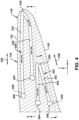
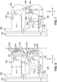
- FIG. 8 shows a schematic side view of first cooling circuit 200 and second cooling circuit 202 overlaid together; and FIGS. 9-14 show top-down cross-sectional views across view lines 9-9, 10-10, 11-11, 12-12, 13-13 and 14-14 in FIG. 8 , respectively.
- Blade 130 may include one or more coolant feed passages 204 defined in airfoil body 136 for delivering a coolant to cooling circuit(s) 200, 202.
- Coolant feed passage(s) 204 may include any, typically radially extending, passage configured to deliver coolant for use in cooling, for example, trailing edge 146.
- Coolant can be any now known or later developed coolant used in a turbomachine blade such as, but not limited to, compressed air from compressor 102, which may be delivered to coolant feed passage(s) 204 through various plenums or casings of the turbomachine and/or blades thereof.
- Coolant feed passages 204 may be part of a coolant feed/reuse circuit 150 ( FIG. 3 ).
- Blade 130 may also include one or more a coolant reuse passages 206 defined in airfoil body 136 for collecting coolant from cooling circuit(s) 200, 202 for reuse in cooling other parts of the blade.
- Coolant reuse passage(s) 206 may include any typically radially extending passage configured to collect coolant from cooling circuit(s) 200, 202.
- Coolant reuse passage(s) 206 may route used coolant to other parts of airfoil body 136 or parts of blade 130, e.g., tip, tip shroud, etc., or it may route used coolant to exterior surfaces of airfoil body 136, e.g., for film cooling. In the latter case, as shown in FIG. 4 , coolant reuse passage(s) 206 may include vent openings 208 to pressure side 140 and/or suction side 142.
- two coolant feed passages 204 are shown, one for first cooling circuit 200 and one for second cooling circuit 202.
- Other drawings, such as FIG. 8 show a shared coolant feed passage 204 and a shared coolant reuse passage 206. It is emphasized that any number of coolant feed or reuse passages 204, 206 can be employed.
- First cooling circuit 200 is defined in airfoil body 136 or, as will be described, in a coupon body 270 ( FIG. 16 ).
- first cooling circuit 200 is adjacent suction side 142 of airfoil body 136, which is cooler than pressure side 140 of airfoil body 136 during operation in a turbomachine.
- First cooling circuit 200 may include a first rearward (feed or inlet) passage 220 extending toward trailing edge 146 from and fluidly coupled to coolant feed passage 204.
- First rearward passage 220 which extends generally axially, can have any tubular cross-sectional shape, e.g., circular.
- First cooling circuit 200 also includes a first radially spreading return passage 222 extending away from trailing edge 146 toward and fluidly coupled to first coolant reuse passage 206. As shown best in FIGS. 5 , 6 and 8 , radially spreading return passage 222 has a radial extent R1 that is significantly greater than a radial extent R2 of rearward passage 220, e.g., greater than 3 times.
- a set of obstructions 224 such as a pin or fin bank, may be optionally positioned in first radially spreading return passage 222 to increase cooling, improve structural integrity, and/or control back pressure.
- return passage 222 may be partially or completely between rearward passage 220 and a hot gas path (HGP) 226 about suction side 142 of airfoil body 136, which limits the amount of energy picked up by coolant before entering trailing edge 146. In this manner, most of the coolant's energy is used in trailing edge 146 rather than prior to trailing edge 146. Coolant returning in return passage 222 may be reused in any manner, e.g., film cooling for suction side 142 and/or pressure side 140. As shown in FIGS. 5 , 6 and 8 , first rearward passage 220 is radially offset from first radially spreading return passage 222 along a radial axis R of airfoil body 136.
- HGP hot gas path
- first cooling circuit 200 also may include a first radially extending turn passage 230 (hereafter "turn passage 230") coupling first rearward passage 220 and first radially spreading return passage 222.
- Turn passage 230 may extend any radial extent R3 ( FIG. 8 ) necessary to fluidly couple rearward passage 220 and return passage 222.
- turn passage 230 may have a first circumferential width W1 at a forward end thereof that is greater than a second circumferential width W2 at an aft end thereof.
- the elliptical shape near the aft end has a length-to-width (L/W2)(see e.g., FIG. 9 ) ratio of between 1:1 and 4:1, inclusive of end values.
- L/W2 length-to-width
- coolant passes as close as possible to trailing edge 146 in turn passage 230, and a shape of trailing edge 146 can be more narrow and/or pointed compared to previous blades to improve aero-performance.
- return passage 222 may fluidly couple to turn passage 230 via a coupling passage 232 that is radially smaller (R4) than return passage 222 (R2), i.e., it has a smaller cross-sectional area.
- a coolant flow (dark arrows) may travel axially rearwardly through rearward passage 220 from feed passage 204, radially outward in turn passage 230 and then axially forward starting in coupling passage 232 and may then expand radially as it flows axially forward in return passage 220 to reuse passage 206. Coolant flows radially outward in turn passage 230 and over a separating wall 236 between turn passage 230 and return passage 222.
- a first set of obstructions 238 may be positioned in turn passage 230.
- Obstructions 238 can take the form of any structure typically used to improve structural integrity of a passage, create back pressure and/or improve heat transfer of a coolant flowing therethrough.
- obstructions 238 may be cylindrical pins having a circular cross-section.
- obstructions 238 may be polygonal pegs having polygonal cross-sections, e.g., rectangular, square, pentagonal, etc.
- the size and spacing of obstructions 238 that creates a specific density of obstructions can be selected to control, for example, heat transfer and back pressure in turn passage 230.
- obstruction density may be increased to increase back pressure, which allows vent passages 240 (described herein) through trailing edge 146 to provide more direct exit of coolant, increases total flow rate though the cooling features, and increases cold side surface area for heat transfer.
- obstructions 238 enhance heat transfer and increase the surface area available to transfer energy to the coolant.
- Obstructions 238 also act as a metering area, allowing, for example, an increased number of vent passages 240 to be used on pressure side 140, increasing coolant film coverage. Obstructions 238 also add to the structural integrity of trailing edge 146.
- obstructions 238 were square and had side dimensions of 0.305-1.524 millimeters (0.012 to 0.060 inches) with spacing ranging from 1.07-1.73 times the side dimensions in a transverse-to-flow direction and 0.41-1.45 times the side dimensions in a flow direction (see arrows).
- obstructions 238 had circular cross-sectional diameters of 0.305-1.067 (0.012-0.042 inches) with spacings ranging from 1.2-3 times the diameter in the transverse-to-flow direction and 1.1-1.7 times the diameter in the flow direction.
- the density of set of obstructions 238 can be selected to control, for example, structural strength and/or back pressure.
- obstructions 238 in turn passages 230 may be the same throughout a given blade 130, or they may vary depending on, for example, radial location, turn passage size or shape, required heat transfer, required structural strength, number of vent passages 240 to be used, among other factors.
- blade 130 may also include a plurality of vent passages 240 extending from radially extending turn passage 230 through trailing edge 146 of airfoil body 136. Coolant can vent through trailing edge 146 by way of vent passages 240. Any number of vent passages 240 may extend from turn passage 230 and may be at any angle/orientation, cross-sectional size or shape, and number, desired to create a particular coolant flow and/or to eliminate the need for any minimum trailing edge thickness based on manufacturing tolerances. Vent passages 240 may be angled toward pressure side 140 and/or suction side 142. Vent passages 240 provide a more direct exit for coolant flow, increasing the total flow rate through trailing edge 146 and also increasing the cold-side surface area for heat transfer.
- blade 130 may also optionally include second cooling circuit 202 defined in airfoil body 136.
- Second cooling circuit 202 is defined in airfoil body 136 or, as will be described, in coupon body 270 ( FIG. 16 ).
- second cooling circuit 202 is adjacent pressure side 140 of airfoil body 136.
- second cooling circuit 202 provides cooling near pressure side 140 of airfoil body 136, which is hotter than suction side 142 of airfoil body 136 during operation of a turbomachine.
- first cooling circuit 200 is circumferentially offset from the second cooling circuit 202 in airfoil body 136.
- second cooling circuit 202 also acts as a buffer to protect coolant in first cooling circuit 200 from excessive heat transfer (e.g., from pressure side 140 of airfoil body 136) prior to reaching trailing edge 146. That is, second cooling circuit 202 shields incoming coolant in first cooling circuit 200 from heat transfer in addition to cooling pressure side 140 of airfoil body 136.
- Second cooling circuit 202 is somewhat similar in shape to first cooling circuit 200.
- Second cooling circuit 202 may include a second rearward (feed or inlet) passage 250 extending toward trailing edge 146 (but not reaching it) from and fluidly coupled to coolant feed 204.
- Second rearward passage 250 which extends generally axially, can have any tubular cross-sectional shape, e.g., circular.
- Coolant feed 204 coupled to second rearward passage 250 may be a separate coolant feed (see e.g., FIGS. 4-5 ) from that of first cooling circuit 200, or it may be a shared coolant feed 204 (see e.g., FIG. 8 ).
- Second cooling circuit 202 also includes a second radially spreading return passage 252 extending away from trailing edge 146 toward and fluidly coupled to a second coolant reuse passage 206 defined in airfoil body 136.
- Second coolant reuse passage 206 may be a separate coolant reuse passage 206 (see e.g., FIGS. 4-5 ) from that of first cooling circuit 200, or it may be a shared coolant reuse passage 206 (see e.g., FIG. 8 ).
- radially spreading return passage 252 has a radial extent R5 that is significantly greater than a radial extent R6 of rearward passage 250, e.g., greater than 3 times.
- a set of obstructions 256 such as a pin or fin bank, may be positioned in second radially spreading return passage 252 to increase cooling, improve structural integrity, and/or control back pressure. As shown best in FIGS.
- return passage 252 may be partially or completely between rearward passage 250 and a hot gas path (HGP) 258 about pressure side 140 of airfoil body 136, which limits the amount of energy picked up by coolant in second cooling circuit 202 before entering trailing edge 146. In this manner, most of the coolant's energy is used in trailing edge 146 rather than prior to trailing edge 146. Coolant returning in return passage 252 may be reused in any manner, e.g., film cooling for suction side 142 and/or pressure side 140. As shown in FIGS. 5 , 6 and 8 , second rearward passage 250 is radially offset from second radially spreading return passage 252 along a radial axis R of airfoil body 136.
- HGP hot gas path
- Second coolant circuit 202 also includes a second radially extending turn passage 260 (hereafter “turn passage 260") coupling second rearward passage 250 and second radially spreading return passage 252.
- Turn passage 260 may extend any radial extent R7 ( FIGS. 7 , 8 ) necessary to fluidly couple rearward passage 250 and return passage 252 of second cooling circuit 202.
- second rearward passage 250 is radially offset from second radially spreading return passage 252 along radial axis R of airfoil body 136. As illustrated for example in FIG.
- return passage 252 may fluidly couple to turn passage 250 via a coupling passage 262 that is radially smaller (R8) than return passage 252 (R5), i.e., it has a smaller cross-sectional area.
- a coolant flow (dark arrows) may travel axially rearwardly through rearward passage 250 from feed passage 204, radially outward in turn passage 260 and then axially forward starting in coupling passage 262 before expanding as it flows axially forward in return passage 252 to reuse passage 206. Coolant flows radially outward in turn passage 260 and over a separating wall 264 between turn passage 260 and return passage 252.
- any number of first or second cooling circuits 200, 202 may be radially positioned in blade 130. That is, blade 130 may include a plurality of the first cooling circuits 200 radially spaced in airfoil body 136 and a plurality of second cooling circuits 202 radially spaced in airfoil body 136. While two of each are shown in FIGS. 6 and 7 , any number may be used, i.e., one of each or three or more.
- FIG. 15 shows a perspective view of a preexisting turbine rotor blade 272 (hereinafter "blade 272").
- Blade 272 may include external and internal structure as described relative to turbine rotor blade 130 of FIG. 3 .
- Blade 272 includes airfoil body 136.
- Airfoil body 136 of blade 272 includes pressure side 140, i.e., a concave pressure side (PS) outer wall, and circumferentially or laterally opposite suction side 142, i.e., a convex suction side (SS) outer wall, extending axially between opposite leading and trailing edges 144, 146, respectively.
- Pressure side 140 and suction side 142 are connected by leading edge 144 and trailing edge 146 and extend in the radial direction from platform 134 to an outboard tip 148.
- Outboard tip 148 is shown without a tip shroud (e.g., tip shroud 126 in FIG. 2 ).
- a radially extending coolant feed/reuse circuit 150 may extend between walls 140, 142.
- Blade 272 is shown with a cutout 280 positioned along the aft end of the airfoil body 136 (that is, a portion encompassing trailing edge 146).
- cutout 280 is a predetermined area (shown by dashed lines) that encompasses trailing edge 146 and that is removed from airfoil body 136, i.e., a predetermined portion extending forward from trailing edge 146.
- Cutout 280 can be removed by any now known or later developed metal cutting technique, e.g., welding torch, electrical discharge machining (EDM), laser cutting, water jet cutting, etc.
- EDM electrical discharge machining
- cutout 280 includes most, if not all, of a radial extent of airfoil body 136. It is emphasized, however, that cutout 280 can include any portion of airfoil body 136 within which first and/or second cooling circuits 200, 202 ( FIGS. 4-14 ) in trailing edge 146 may be desired.
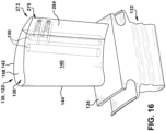
- coupon 270 is coupled in cutout 280 ( FIG. 15 ) to replace a predetermined area ( FIG. 15 ) of airfoil body 136 that encompasses trailing edge 146.
- coupon 270 includes the structure described herein relative to first cooling circuits 200 and, where desired, second cooling circuits 202. More particularly, coupon 270 includes a coupon body 284 including first cooling circuit(s) 200 ( FIGS. 4-6 and 8-14 ) defined therein and, optionally, second cooling circuit(s) 202 ( FIGS. 4-5 , 7 and 11-14 ). First cooling circuit 200 and second cooling circuit 202 may be arranged as described herein. Coupon 270 can be the same size as cutout 280 or larger or smaller.
- first and second cooling circuits 200, 202 can be obtained from any coolant feed 204 (see e.g., FIGS. 4-5 , 8 ) and may be reused as described herein.
- FIG. 17 is a perspective view of a blade 130 in the form of a turbine nozzle 116 of the type in which embodiments of the present disclosure may be employed.
- Nozzle 116 may be held in turbine assembly 108 ( FIG. 2 ) by radially outer platform 118 and radially inner platform 120.
- airfoil body 136 is the active component of blade 130 (nozzle 116) that intercepts the flow of working fluid and directs the flow where desired.
- Airfoil body 136 of nozzle 116 includes pressure side 140, i.e., a concave pressure side (PS) outer wall, and a circumferentially or laterally opposite suction side 142, i.e., a convex suction side (SS) outer wall, extending axially between opposite leading and trailing edges 144, 146, respectively.
- Pressure side 140 and suction side 142 are connected by leading edge 144 and trailing edge 146 and extend in the radial direction from radially inner platform 120 to radially outer platform 118.
- a radially extending coolant feed/reuse circuit 150 may extend between walls 140, 142.
- Nozzle 116 may include first cooling circuit 200 ( FIGS.
- a coupon 270 as described relative to FIGS. 15 and 16 , may be applied to nozzle 116 in a similar fashion as described relative to turbine rotor blade 122.
- Blade 130 (rotating blades and stationary vanes) or coupon 270 may include any metal or metal compound capable of withstanding the environment in which used. Blade 130 and coupon 270 may be made using any now known or later developed manufacturing technique. However, additive manufacturing allows for blade 130 and coupon 270 to be formed with greatly minimized sizes and shapes, e.g., smaller obstructions and thinner walls of airfoil body 136, many of which improve aerodynamic performance. As used herein, additive manufacturing (AM) may include any process of producing an object through the successive layering of material rather than the removal of material, which is the case with conventional processes. Additive manufacturing can create complex geometries without the use of any sort of tools, molds or fixtures, and with little or no waste material.
- additive manufacturing additive manufacturing
- Additive manufacturing processes may include, but are not limited to: 3D printing, rapid prototyping (RP), direct digital manufacturing (DDM), binder jetting, selective laser melting (SLM) and direct metal laser melting (DMLM).
- RP rapid prototyping
- DDM direct digital manufacturing
- SLM selective laser melting
- DMLM direct metal laser melting
- Embodiments of the disclosure can improve aerodynamic efficiency of turbomachine blades by providing a trailing edge having a sharper turn than conventional blades.
- FIG. 18 shows a schematic cross-sectional view of a conventional trailing edge 300 overlaid with a trailing edge 302, according to embodiments of the disclosure.
- trailing edge 302 is more pointed or sharper than conventional trailing edge 300, the latter of which has a more uniform radius R9 and more square profile.
- trailing edge 302 is more highly elliptical.
- a conventional trailing edge 300 typically has an ellipse ratio of less than or equal to 1 as illustrated by the ellipse 304 - see major and minor axes labeled 304maj, 304min, respectively.
- Ellipse ratio is equal to major axis divided by minor axis.
- the major axis as defined herein is generally along the mean camber line 305 of airfoil body 136, it is not perpendicular to the mean camber line 305.
- the ellipse ratio may be the result of manufacturing of the trailing edge and/or the provision of thermal barrier coatings thereon.
- an ellipse ratio of greater than 1 is challenging to manufacture because it is difficult to sufficiently cool.
- an ellipse ratio of trailing edge 302 can be between 1.1 to 4 - see major and minor axes labeled 302maj, 302min, respectively.
- the ellipse ratio of trailing edge 302 can be between 1.1 to 3.
- the ellipse ratio of trailing edge 302 can be between 1.1 to 2.
- the ellipse ratio of trailing edge 302 can be between 1.1-1.5.
- a location of trailing edge 302 may be defined based on where airfoil body 136 transitions from the more linear pressure side 140 or suction side 142 to have more curvature, i.e., with a large gradient in curvature typical of a trailing edge compared to the rest of airfoil body 136.
- the transition in curvature may be identified, for example, using a curvilinear combs graphical analysis tool available in any now known or later developed computer aided graphics (CAD) design system.
- CAD computer aided graphics
- Embodiments of the disclosure can also improve aerodynamic efficiency of turbomachine blades, e.g., by using thinner walls, with reduced coolant flow to reduce trailing edge temperatures.
- the obstructions in the turn passage also provide additional structural strength.
- the coupons can provide internal cooling structures not previously present in the blade, thus providing improved cooling and aero-performance and lengthening a lifespan of the part.
- Approximating language may be applied to modify any quantitative representation that could permissibly vary without resulting in a change in the basic function to which it is related. Accordingly, a value modified by a term or terms, such as “about,” “approximately” and “substantially,” are not to be limited to the precise value specified. In at least some instances, the approximating language may correspond to the precision of an instrument for measuring the value.
- range limitations may be combined and/or interchanged; such ranges are identified and include all the sub-ranges contained therein unless context or language indicates otherwise. "Approximately,” as applied to a particular value of a range, applies to both end values and, unless otherwise dependent on the precision of the instrument measuring the value, may indicate +/- 10% of the stated value(s).
Landscapes
- Engineering & Computer Science (AREA)
- Mechanical Engineering (AREA)
- General Engineering & Computer Science (AREA)
- Architecture (AREA)
- Turbine Rotor Nozzle Sealing (AREA)
Abstract
Description
- This invention was made with government support under Grant No.
DE-FE0031616 - The disclosure relates generally to turbomachine blades and, more particularly, to a turbomachine blade having a trailing edge cooling circuit with a turn passage having a set of obstructions therein.
- Turbomachine blades, such as rotor blades or stationary vanes, include airfoils that accelerate flow through contraction of area and the introduction of tangential velocity. The trailing edges of the airfoils are difficult to cool due to the small volume of material compared to the large heat loads at that location. Notably, the mismatch between external surface area and the internal surface makes any cooling solution challenging. To address this situation, trailing edges are typically cooled with coolant flows having high flow rates. The high flow rates to the trailing edges decreases the coolant that can be used elsewhere. The high flow rates also require the trailing edges to have minimum thicknesses to accommodate the passages that deliver the coolant flow and create the necessary cold-to-hot area ratio. The minimum thicknesses do not allow for sharper trailing edges that would improve aerodynamic performance.
- All aspects, examples and features mentioned below can be combined in any technically possible way.
- An aspect of the disclosure provides a turbomachine blade, comprising: an airfoil body having a pressure side and a suction side connected by a leading edge and a trailing edge; a coolant feed passage defined in the airfoil body; a first coolant reuse passage defined in the airfoil body; a first cooling circuit defined in the airfoil body, the first cooling circuit including: a first rearward passage extending toward the trailing edge from and fluidly coupled to the coolant feed passage; a first radially spreading return passage extending away from the trailing edge toward and fluidly coupled to the first coolant reuse passage; and a first radially extending turn passage coupling the first rearward passage and the first radially spreading return passage; and a first set of obstructions positioned in the first radially extending turn passage.
- Another aspect of the disclosure includes any of the preceding aspects, and further comprises a plurality of vent passages extending from the first radially extending turn passage through the trailing edge of the airfoil body.
- Another aspect of the disclosure includes any of the preceding aspects, and the first rearward passage is radially offset from the first radially spreading return passage along a radial axis of the airfoil body.
- Another aspect of the disclosure includes any of the preceding aspects, and further comprises a second set of obstructions positioned in the first radially spreading return passage.
- Another aspect of the disclosure includes any of the preceding aspects, and further comprises: a second cooling circuit defined in the airfoil body, the second cooling circuit including: a second rearward passage extending toward the trailing edge from and fluidly coupled to the coolant feed passage; a second radially spreading return passage extending away from the trailing edge toward and fluidly coupled to a second coolant reuse passage defined in the airfoil body; and a second radially extending turn passage coupling the second rearward passage and the second radially spreading return passage; wherein the second rearward passage is radially offset from the second radially spreading return passage along the radial axis of the airfoil body.
- Another aspect of the disclosure includes any of the preceding aspects, and the first cooling circuit is circumferentially offset from the second cooling circuit in the airfoil body.
- Another aspect of the disclosure includes any of the preceding aspects, and further comprises a second set of obstructions positioned in the second radially spreading return passage.
- Another aspect of the disclosure includes any of the preceding aspects, and further comprises a plurality of the first cooling circuits radially spaced in the airfoil body, and a plurality of second cooling circuits radially spaced in the airfoil body.
- Another aspect of the disclosure includes any of the preceding aspects, and the trailing edge has an ellipse ratio between 1.1 and 4.
- Another aspect of the disclosure includes any of the preceding aspects, and the first cooling circuit is adjacent the suction side of the airfoil body, and the second cooling circuit is adjacent the pressure side of the airfoil body.
- Another aspect of the disclosure includes any of the preceding aspects, and the first radially extending turn passage has a first circumferential width at a forward end thereof that is greater than a second circumferential width at an aft end thereof.
- An aspect of the disclosure provides a coupon for replacing a cutout of a predetermined area in an airfoil body of a turbomachine blade, the airfoil body having a pressure side and a suction side connected by a leading edge and a trailing edge, the cutout within the trailing edge of the airfoil body, the coupon comprising: a coupon body; a first cooling circuit defined in the coupon body, the first cooling circuit including: a first rearward passage extending toward the trailing edge from and fluidly coupled to a coolant feed passage defined in at least one of the coupon body and the airfoil body; a first radially spreading return passage extending away from the trailing edge toward and fluidly coupled to a first coolant reuse passage defined in at least one of the coupon body and the airfoil body; a first radially extending turn passage coupling the first rearward passage and the first radially spreading return passage; and a first set of obstructions positioned in the first radially extending turn passage.
- Another aspect of the disclosure includes any of the preceding aspects, and further comprises a plurality of vent passages extending from the first radially extending turn passage through the trailing edge of the coupon body.
- Another aspect of the disclosure includes any of the preceding aspects, and the first rearward passage is radially offset from the first radially spreading return passage along a radial axis of the airfoil body.
- Another aspect of the disclosure includes any of the preceding aspects, and further comprises a second set of obstructions positioned in the first radially spreading return passage.
- Another aspect of the disclosure includes any of the preceding aspects, and further comprises: a second cooling circuit defined in the coupon body, the second cooling circuit including: a second rearward passage extending toward the trailing edge from and fluidly coupled to the coolant feed passage; a second radially spreading return passage extending away from the trailing edge toward and fluidly coupled to a second coolant reuse passage defined in at least one of the coupon body and the airfoil body; and a second radially extending turn passage coupling the second rearward passage and the second radially spreading return passage, wherein the second rearward passage is radially offset from the second radially spreading return passage along the radial axis of the airfoil body.
- Another aspect of the disclosure includes any of the preceding aspects, and the trailing edge has an ellipse ratio between 1.1 and 4.
- Another aspect of the disclosure includes any of the preceding aspects, and the first radially extending turn passage has a first circumferential width at a forward end thereof that is greater than a second circumferential width at an aft end thereof.
- An aspect of the disclosure provides a gas turbine system, comprising: a compressor; a combustor; and a turbine, the turbine including a turbomachine blade including a trailing edge cooling system, the turbomachine blade including: an airfoil body having a pressure side and a suction side connected by a leading edge and a trailing edge; a coolant feed passage defined in the airfoil body; a first coolant reuse passage defined in the airfoil body; a first cooling circuit defined in the airfoil body, the first cooling circuit including: a first rearward passage extending toward the trailing edge from and fluidly coupled to the coolant feed passage; a first radially spreading return passage extending away from the trailing edge toward and fluidly coupled to the first coolant reuse passage; and a first radially extending turn passage coupling the first rearward passage and the first radially spreading return passage; and a first set of obstructions positioned in the first radially extending turn passage.
- Two or more aspects described in this disclosure, including those described in this summary section, may be combined to form implementations not specifically described herein.
- The details of one or more implementations are set forth in the accompanying drawings and the description below. Other features, objects, and advantages will be apparent from the description and drawings, and from the claims.
- These and other features of this disclosure will be more readily understood from the following detailed description of the various aspects of the disclosure taken in conjunction with the accompanying drawings that depict various embodiments of the disclosure, in which:
-
FIG. 1 shows a schematic cross-sectional view of an illustrative turbomachine in the form of a gas turbine system; -
FIG. 2 shows a cross-sectional view of an illustrative gas turbine assembly with a three-stage turbine that may be used with the gas turbine system inFIG. 1 ; -
FIG. 3 shows a perspective view of an illustrative turbomachine blade in the form of a turbine rotor blade of the type in which embodiments of the disclosure may be employed; -
FIG. 4 shows a schematic top-down view of cooling circuit(s) in a trailing edge of an airfoil body such as of the turbine rotor blade ofFIG. 3 , according to embodiments of the disclosure; -
FIG. 5 shows a schematic perspective view of cooling circuits ofFIG. 4 apart from an airfoil body, according to embodiments of the disclosure; -
FIG. 6 shows a schematic side view of a plurality of first cooling circuits, taken along view line 6-6 inFIG. 4 ; -
FIG. 7 shows a schematic side view of a plurality of second cooling circuits, taken along view line 7-7 inFIG. 4 ; -
FIG. 8 shows a schematic side view of a first cooling circuit and a second cooling circuit, as inFIG. 6 and 7 , overlaid together; -
FIG. 9 shows a top-down cross-sectional view of the cooling circuits across view line 9-9 inFIG. 8 ; -
FIG. 10 shows a top-down cross-sectional view of the cooling circuits across view line 10-10 inFIG. 8 ; -
FIG. 11 shows a top-down cross-sectional view of the cooling circuits across view line 11-11 inFIG. 8 ; -
FIG. 12 shows a top-down cross-sectional view of the cooling circuits across view line 12-12 inFIG. 8 ; -
FIG. 13 shows a top-down cross-sectional view of the cooling circuits across view line 13-13 inFIG. 8 ; -
FIG. 14 shows a top-down cross-sectional view of the cooling circuits across view line 14-14 inFIG. 8 ; -
FIG. 15 shows a perspective view of a blade including a cutout for filling with a coupon including cooling circuit(s), according to embodiments of the disclosure; -
FIG. 16 shows a perspective view of a blade including the coupon including cooling circuit(s), according to embodiments of the disclosure; -
FIG. 17 shows a perspective view of an illustrative turbomachine blade in the form of a turbine nozzle of the type in which embodiments of the disclosure may be employed; and -
FIG. 18 shows a schematic cross-sectional view of a conventional trailing edge overlaid with a trailing edge according to embodiments of the disclosure. - It is noted that the drawings of the disclosure are not necessarily to scale. The drawings are intended to depict only typical aspects of the disclosure and therefore should not be considered as limiting the scope of the disclosure. In the drawings, like numbering represents like elements among the drawings.
- As an initial matter, in order to clearly describe the subject matter of the current disclosure, it will become necessary to select certain terminology when referring to and describing relevant machine components within a turbomachine and/or a turbomachine blade. To the extent possible, common industry terminology will be used and employed in a manner consistent with its accepted meaning. Unless otherwise stated, such terminology should be given a broad interpretation consistent with the context of the present application and the scope of the appended claims. Those of ordinary skill in the art will appreciate that often a particular component may be referred to using several different or overlapping terms. What may be described herein as being a single part may include and be referenced in another context as consisting of multiple components. Alternatively, what may be described herein as including multiple components may be referred to elsewhere as a single part.
- In addition, several descriptive terms may be used regularly herein, and it should prove helpful to define these terms at the onset of this section. These terms and their definitions, unless stated otherwise, are as follows. As used herein, "downstream" and "upstream" are terms that indicate a direction relative to the flow of a fluid, such as the working fluid through the turbine engine or, for example, the flow of air through the combustor or coolant through one of the turbine's component systems. The term "downstream" corresponds to the direction of flow of the fluid, and the term "upstream" refers to the direction opposite to the flow (i.e., the direction from which the flow originates). The terms "forward" and "aft," without any further specificity, refer to directions, with "forward" referring to the front or compressor end of the engine, and "aft" referring to the rearward section of the turbomachine. In context herein, "forward" refers to the leading edge of a turbomachine blade, and "aft" or "rear" refers to the trailing edge of a turbomachine blade.
- It is often required to describe parts that are disposed at differing radial positions with regard to a center axis. The term "radial" refers to movement or position perpendicular to an axis. For example, if a first component resides closer to the axis than a second component, it will be stated herein that the first component is "radially inward" or "inboard" of the second component. If, on the other hand, the first component resides further from the axis than the second component, it may be stated herein that the first component is "radially outward" or "outboard" of the second component. The term "axial" refers to movement or position parallel to the axis of rotation of the turbine system, or in a chordal direction between leading and trailing edges of an airfoil. Finally, the term "circumferential" refers to movement or position around an axis. It will be appreciated that such terms may be applied in relation to the center axis of the turbine. In the figures (see, e.g., the legend in
FIG. 3 ), an axial orientation is referenced with an "A"; a radial orientation is referenced with an "R"; and a circumferential orientation (about axis A) is referenced with a "C". - In addition, several descriptive terms may be used regularly herein, as described below. The terms "first", "second", and "third" may be used interchangeably to distinguish one component from another and are not intended to signify location or importance of the individual components.
- The terminology used herein is for the purpose of describing particular embodiments only and is not intended to be limiting of the disclosure. As used herein, the singular forms "a", "an" and "the" are intended to include the plural forms as well, unless the context clearly indicates otherwise. It will be further understood that the terms "comprises," "comprising," "including," and/or "having," when used in this specification, specify the presence of stated features, integers, steps, operations, elements, and/or components but do not preclude the presence or addition of one or more other features, integers, steps, operations, elements, components, and/or groups thereof. "Optional" or "optionally" means that the subsequently described event or circumstance may or may not occur or that the subsequently described component or element may or may not be present, and that the description includes instances where the event occurs or the component is present and instances where it does not or is not present.
- Where an element or layer is referred to as being "on," "engaged to," "connected to" or "coupled to" another element or layer, it may be directly on, engaged to, connected to, or coupled to the other element or layer, or intervening elements or layers may be present. In contrast, when an element is referred to as being "directly on," "directly engaged to," "directly connected to" or "directly coupled to" another element or layer, there are no intervening elements or layers present. Other words used to describe the relationship between elements should be interpreted in a like fashion (e.g., "between" versus "directly between," "adjacent" versus "directly adjacent," etc.). As used herein, the term "and/or" includes any and all combinations of one or more of the associated listed items.
- As indicated above, the disclosure provides a turbomachine blade and a coupon for a turbomachine blade. The turbomachine blade may include an airfoil body having a pressure side and a suction side connected by a leading edge and a trailing edge, a coolant feed passage defined in the airfoil body, and a coolant reuse (collection) passage defined in the airfoil body. The blade may also include a first cooling circuit defined in the airfoil body. The first cooling circuit may include a rearward passage extending toward the trailing edge from and fluidly coupled to the coolant feed passage, and a radially spreading return passage extending away from the trailing edge toward and fluidly coupled to the coolant reuse passage. The first cooling circuit may also include a radially extending turn passage coupling the rearward passage and the radially spreading return passage. A first set of obstructions may be positioned in the radially extending turn passage.
- The obstructions, created through additive manufacturing, have a density that allows a lower coolant flow rate and creates sufficient back pressure to allow some of the coolant to exit through vent openings in the trailing edge. The obstructions in the turn passage also provide additional structural strength and allow the trailing edge to have a sharper turn and use thinner walls, thus improving aerodynamic performance of the blade. Coolant not exiting through the vent openings can be reused, for example, for film cooling an exterior surface of the airfoil body or for other purposes.
- A second cooling circuit may also be provided, e.g., on a pressure side of the airfoil body, to shield parts of the first cooling circuit from a heat load, thus improving the effectiveness of coolant in the first cooling circuit.
-
FIG. 1 shows a schematic illustration of anillustrative turbomachine 100 in the form of a combustion or gas turbine system.Turbomachine 100 includes acompressor 102 and acombustor 104.Combustor 104 includes acombustion region 105 and afuel nozzle assembly 106.Turbomachine 100 also includes aturbine 108 and a common compressor/turbine shaft 110 (sometimes referred to as rotor 110). In one embodiment, the combustion turbine system is a 7HA or 9HA engine, commercially available from General Electric Company, Greenville, S.C. The present disclosure is not limited to any one particular GT system and may be implemented in connection with other engines including, for example, the other HA, F, B, LM, GT, TM and E-class engine models of General Electric Company and engine models of other companies. Further, the teachings of the disclosure are not necessarily applicable to only a GT system and may be applied to other types of turbomachines, e.g., steam turbines, jet engines, compressors, etc. - In operation, air flows through
compressor 102, and compressed air is supplied tocombustor 104. Specifically, the compressed air is supplied to fuelnozzle assembly 106 that is integral tocombustor 104.Assembly 106 is in flow communication withcombustion region 105.Fuel nozzle assembly 106 is also in flow communication with a fuel source (not shown inFIG. 1 ) and channels fuel and air tocombustion region 105.Combustor 104 ignites and combusts fuel.Combustor 104 is in flow communication withturbine 108 within which gas stream thermal energy is converted to mechanical rotational energy.Turbine 108 is rotatably coupled to and drivesrotor 110.Compressor 102 also is rotatably coupled torotor 110. In the illustrative embodiment, there are a plurality ofcombustors 104 andfuel nozzle assemblies 106. -
FIG. 2 shows a cross-sectional view of anillustrative turbine 108 of turbomachine 100 (FIG. 2 ) with three turbine stages that may be used with the gas turbine system inFIG. 2 . Each turbine stage ofturbine 108 includes a row ofstationary blades 112 coupled to a stationary casing ofturbomachine 100 and positioned axially adjacent a rotating row ofblades 114. Row ofblades 112 includes stationary blades or nozzles 116 (vanes). Eachnozzle 116 may be held inturbine assembly 108 by a radiallyouter platform 118 and a radiallyinner platform 120. Row ofrotating blades 114 inturbine 108 includes rotating blades 122 coupled torotor 110 and rotating with therotor 110. Rotating blades 122 include a radially inward platform 124 (at root of blade) coupled torotor 110 and, optionally, may include a radially outward tip shroud 126 (at tip of blade). As used herein, the term "blade" shall refer collectively to stationary blades for vanes ornozzles 116 and rotating blades 122, unless otherwise stated. -
FIG. 3 is a perspective view of ablade 130 in the form of a turbine rotor blade 122 of the type in which embodiments of the present disclosure may be employed.Blade 130 includes aroot 132 by whichblade 130 attaches to rotor 110 (FIG. 2 ).Root 132 may include a dovetail configured for mounting in a corresponding dovetail slot in the perimeter of the rotor disc.Root 132 may further include a shank that extends between the dovetail and aplatform 134, which is disposed at the junction of anairfoil body 136 androot 132 and defines a portion of the inboard boundary of the flow path throughturbine 108. It will be appreciated thatairfoil body 136 is the active component ofrotor blade 130 that intercepts the flow of working fluid and induces the rotor disc to rotate. -
Airfoil body 136 ofblade 130 includes apressure side 140, i.e., a concave pressure side (PS) outer wall, and a circumferentially or laterally oppositesuction side 142, i.e., a convex suction side (SS) outer wall, extending axially between opposite leading and trailingedges Pressure side 140 andsuction side 142 are connected by leadingedge 144 and trailingedge 146 and also extend in the radial direction fromplatform 134 to anoutboard tip 148.Outboard tip 148 is shown without a tip shroud (e.g.,tip shroud 126 inFIG. 2 ). A radially extending coolant feed/reuse circuit 150 may extend betweenwalls blade 130 of this example is a turbine rotor blade 122 (FIGS. 2-3 ), it will be appreciated that the present disclosure also may be applied to other types of blades withinturbine engine 100, including turbine nozzles 116 (FIGS. 2 and17 ) (vanes). The usage of rotor blades in the several embodiments described herein is merely illustrative unless otherwise stated. -
FIGS. 4-14 show various views of cooling circuit(s) defined inairfoil body 136 and, in particular, in trailingedge 146, according to embodiments of the disclosure.FIG. 4 shows a schematic top-down view an embodiment of afirst cooling circuit 200 and an optionalsecond cooling circuit 202.FIGS. 5-7 show the portion of coolingcircuits 200 and/or 202 in trailingedge 146 within a non-limiting position in blade 130 (designated as position "B" inFIG. 3 ). More particularly,FIG. 5 shows a schematic perspective view of coolingcircuits FIG. 4 );FIG. 6 shows a schematic side view of an embodiment of a plurality offirst cooling circuits 200 along view line 6-6 inFIG. 4 ; andFIG. 7 shows a schematic side view of a plurality ofsecond cooling circuits 202 along view line 7-7 inFIG. 4 .FIG. 8 shows a schematic side view offirst cooling circuit 200 andsecond cooling circuit 202 overlaid together; andFIGS. 9-14 show top-down cross-sectional views across view lines 9-9, 10-10, 11-11, 12-12, 13-13 and 14-14 inFIG. 8 , respectively. - Blade 130 (
FIG. 3 ) may include one or morecoolant feed passages 204 defined inairfoil body 136 for delivering a coolant to cooling circuit(s) 200, 202. Coolant feed passage(s) 204 may include any, typically radially extending, passage configured to deliver coolant for use in cooling, for example, trailingedge 146. Coolant can be any now known or later developed coolant used in a turbomachine blade such as, but not limited to, compressed air fromcompressor 102, which may be delivered to coolant feed passage(s) 204 through various plenums or casings of the turbomachine and/or blades thereof.Coolant feed passages 204 may be part of a coolant feed/reuse circuit 150 (FIG. 3 ). - Blade 130 (
FIG. 3 ) may also include one or more acoolant reuse passages 206 defined inairfoil body 136 for collecting coolant from cooling circuit(s) 200, 202 for reuse in cooling other parts of the blade. Coolant reuse passage(s) 206 may include any typically radially extending passage configured to collect coolant from cooling circuit(s) 200, 202. Coolant reuse passage(s) 206 may route used coolant to other parts ofairfoil body 136 or parts ofblade 130, e.g., tip, tip shroud, etc., or it may route used coolant to exterior surfaces ofairfoil body 136, e.g., for film cooling. In the latter case, as shown inFIG. 4 , coolant reuse passage(s) 206 may include ventopenings 208 topressure side 140 and/orsuction side 142. - In some of the drawings, two
coolant feed passages 204 are shown, one forfirst cooling circuit 200 and one forsecond cooling circuit 202. Other drawings, such asFIG. 8 , show a sharedcoolant feed passage 204 and a sharedcoolant reuse passage 206. It is emphasized that any number of coolant feed or reusepassages -
First cooling circuit 200 is defined inairfoil body 136 or, as will be described, in a coupon body 270 (FIG. 16 ). In the example shown,first cooling circuit 200 isadjacent suction side 142 ofairfoil body 136, which is cooler thanpressure side 140 ofairfoil body 136 during operation in a turbomachine.First cooling circuit 200 may include a first rearward (feed or inlet)passage 220 extending toward trailingedge 146 from and fluidly coupled tocoolant feed passage 204. Firstrearward passage 220, which extends generally axially, can have any tubular cross-sectional shape, e.g., circular.First cooling circuit 200 also includes a first radially spreadingreturn passage 222 extending away from trailingedge 146 toward and fluidly coupled to firstcoolant reuse passage 206. As shown best inFIGS. 5 ,6 and8 , radially spreadingreturn passage 222 has a radial extent R1 that is significantly greater than a radial extent R2 ofrearward passage 220, e.g., greater than 3 times. - As shown in the lower return passage in
FIG. 6 , a set ofobstructions 224, such as a pin or fin bank, may be optionally positioned in first radially spreadingreturn passage 222 to increase cooling, improve structural integrity, and/or control back pressure. - As shown best in
FIGS. 4 and5 , returnpassage 222 may be partially or completely betweenrearward passage 220 and a hot gas path (HGP) 226 aboutsuction side 142 ofairfoil body 136, which limits the amount of energy picked up by coolant before entering trailingedge 146. In this manner, most of the coolant's energy is used in trailingedge 146 rather than prior to trailingedge 146. Coolant returning inreturn passage 222 may be reused in any manner, e.g., film cooling forsuction side 142 and/orpressure side 140. As shown inFIGS. 5 ,6 and8 , firstrearward passage 220 is radially offset from first radially spreadingreturn passage 222 along a radial axis R ofairfoil body 136. - As shown in
FIGS. 4 ,5 ,6 ,8-14 ,first cooling circuit 200 also may include a first radially extending turn passage 230 (hereafter "turn passage 230") coupling firstrearward passage 220 and first radially spreadingreturn passage 222.Turn passage 230 may extend any radial extent R3 (FIG. 8 ) necessary to fluidly couplerearward passage 220 and returnpassage 222. As shown for example inFIGS. 5 and9-12 ,turn passage 230 may have a first circumferential width W1 at a forward end thereof that is greater than a second circumferential width W2 at an aft end thereof. The elliptical shape near the aft end (closest to trailing edge 146) has a length-to-width (L/W2)(see e.g.,FIG. 9 ) ratio of between 1:1 and 4:1, inclusive of end values. In this manner, coolant passes as close as possible to trailingedge 146 inturn passage 230, and a shape of trailingedge 146 can be more narrow and/or pointed compared to previous blades to improve aero-performance. - As illustrated for example in
FIG. 8 , returnpassage 222 may fluidly couple to turnpassage 230 via acoupling passage 232 that is radially smaller (R4) than return passage 222 (R2), i.e., it has a smaller cross-sectional area. A coolant flow (dark arrows) may travel axially rearwardly throughrearward passage 220 fromfeed passage 204, radially outward inturn passage 230 and then axially forward starting incoupling passage 232 and may then expand radially as it flows axially forward inreturn passage 220 to reusepassage 206. Coolant flows radially outward inturn passage 230 and over a separatingwall 236 betweenturn passage 230 and returnpassage 222. - Referring to
FIGS. 6 and8 , a first set ofobstructions 238 may be positioned inturn passage 230.Obstructions 238 can take the form of any structure typically used to improve structural integrity of a passage, create back pressure and/or improve heat transfer of a coolant flowing therethrough. In certain embodiments, as shown in thetop turn passage 230 inFIG. 6 ,obstructions 238 may be cylindrical pins having a circular cross-section. In other embodiments, as shown in thebottom turn passage 230 inFIG. 6 and inFIG. 8 ,obstructions 238 may be polygonal pegs having polygonal cross-sections, e.g., rectangular, square, pentagonal, etc. The size and spacing ofobstructions 238 that creates a specific density of obstructions can be selected to control, for example, heat transfer and back pressure inturn passage 230. - In particular, obstruction density may be increased to increase back pressure, which allows vent passages 240 (described herein) through trailing
edge 146 to provide more direct exit of coolant, increases total flow rate though the cooling features, and increases cold side surface area for heat transfer. Hence,obstructions 238 enhance heat transfer and increase the surface area available to transfer energy to the coolant.Obstructions 238 also act as a metering area, allowing, for example, an increased number ofvent passages 240 to be used onpressure side 140, increasing coolant film coverage.Obstructions 238 also add to the structural integrity of trailingedge 146. - In one non-limiting example,
obstructions 238 were square and had side dimensions of 0.305-1.524 millimeters (0.012 to 0.060 inches) with spacing ranging from 1.07-1.73 times the side dimensions in a transverse-to-flow direction and 0.41-1.45 times the side dimensions in a flow direction (see arrows). In another non-limiting example,obstructions 238 had circular cross-sectional diameters of 0.305-1.067 (0.012-0.042 inches) with spacings ranging from 1.2-3 times the diameter in the transverse-to-flow direction and 1.1-1.7 times the diameter in the flow direction. In any event, the density of set ofobstructions 238 can be selected to control, for example, structural strength and/or back pressure. The number, shapes and/or sizes ofobstructions 238 in turn passages 230 (and other obstructions, described herein) may be the same throughout a givenblade 130, or they may vary depending on, for example, radial location, turn passage size or shape, required heat transfer, required structural strength, number ofvent passages 240 to be used, among other factors. - As shown in
FIGS. 6 ,8-11 ,13 and 14 ,blade 130 may also include a plurality ofvent passages 240 extending from radially extendingturn passage 230 through trailingedge 146 ofairfoil body 136. Coolant can vent through trailingedge 146 by way ofvent passages 240. Any number ofvent passages 240 may extend fromturn passage 230 and may be at any angle/orientation, cross-sectional size or shape, and number, desired to create a particular coolant flow and/or to eliminate the need for any minimum trailing edge thickness based on manufacturing tolerances.Vent passages 240 may be angled towardpressure side 140 and/orsuction side 142.Vent passages 240 provide a more direct exit for coolant flow, increasing the total flow rate through trailingedge 146 and also increasing the cold-side surface area for heat transfer. - Referring to
FIGS. 4 ,5 ,7 ,8 and11-14 ,blade 130 may also optionally includesecond cooling circuit 202 defined inairfoil body 136.Second cooling circuit 202 is defined inairfoil body 136 or, as will be described, in coupon body 270 (FIG. 16 ). In the example shown,second cooling circuit 202 isadjacent pressure side 140 ofairfoil body 136. Hence,second cooling circuit 202 provides cooling nearpressure side 140 ofairfoil body 136, which is hotter thansuction side 142 ofairfoil body 136 during operation of a turbomachine. As shown inFIGS. 4 and5 ,first cooling circuit 200 is circumferentially offset from thesecond cooling circuit 202 inairfoil body 136. Hence,second cooling circuit 202 also acts as a buffer to protect coolant infirst cooling circuit 200 from excessive heat transfer (e.g., frompressure side 140 of airfoil body 136) prior to reaching trailingedge 146. That is,second cooling circuit 202 shields incoming coolant infirst cooling circuit 200 from heat transfer in addition to coolingpressure side 140 ofairfoil body 136. -
Second cooling circuit 202 is somewhat similar in shape tofirst cooling circuit 200.Second cooling circuit 202 may include a second rearward (feed or inlet)passage 250 extending toward trailing edge 146 (but not reaching it) from and fluidly coupled tocoolant feed 204. Secondrearward passage 250, which extends generally axially, can have any tubular cross-sectional shape, e.g., circular.Coolant feed 204 coupled to secondrearward passage 250 may be a separate coolant feed (see e.g.,FIGS. 4-5 ) from that offirst cooling circuit 200, or it may be a shared coolant feed 204 (see e.g.,FIG. 8 ).Second cooling circuit 202 also includes a second radially spreadingreturn passage 252 extending away from trailingedge 146 toward and fluidly coupled to a secondcoolant reuse passage 206 defined inairfoil body 136. Secondcoolant reuse passage 206 may be a separate coolant reuse passage 206 (see e.g.,FIGS. 4-5 ) from that offirst cooling circuit 200, or it may be a shared coolant reuse passage 206 (see e.g.,FIG. 8 ). - As shown best in
FIGS. 5 ,7 and8 , radially spreadingreturn passage 252 has a radial extent R5 that is significantly greater than a radial extent R6 ofrearward passage 250, e.g., greater than 3 times. As shown in the lower return passage inFIG. 7 , a set ofobstructions 256, such as a pin or fin bank, may be positioned in second radially spreadingreturn passage 252 to increase cooling, improve structural integrity, and/or control back pressure. As shown best inFIGS. 4 and5 , returnpassage 252 may be partially or completely betweenrearward passage 250 and a hot gas path (HGP) 258 aboutpressure side 140 ofairfoil body 136, which limits the amount of energy picked up by coolant insecond cooling circuit 202 before entering trailingedge 146. In this manner, most of the coolant's energy is used in trailingedge 146 rather than prior to trailingedge 146. Coolant returning inreturn passage 252 may be reused in any manner, e.g., film cooling forsuction side 142 and/orpressure side 140. As shown inFIGS. 5 ,6 and8 , secondrearward passage 250 is radially offset from second radially spreadingreturn passage 252 along a radial axis R ofairfoil body 136. -
Second coolant circuit 202 also includes a second radially extending turn passage 260 (hereafter "turn passage 260") coupling secondrearward passage 250 and second radially spreadingreturn passage 252.Turn passage 260 may extend any radial extent R7 (FIGS. 7 ,8 ) necessary to fluidly couplerearward passage 250 and returnpassage 252 ofsecond cooling circuit 202. As shown best inFIGS. 5 and8 , secondrearward passage 250 is radially offset from second radially spreadingreturn passage 252 along radial axis R ofairfoil body 136. As illustrated for example inFIG. 8 , returnpassage 252 may fluidly couple to turnpassage 250 via acoupling passage 262 that is radially smaller (R8) than return passage 252 (R5), i.e., it has a smaller cross-sectional area. A coolant flow (dark arrows) may travel axially rearwardly throughrearward passage 250 fromfeed passage 204, radially outward inturn passage 260 and then axially forward starting incoupling passage 262 before expanding as it flows axially forward inreturn passage 252 to reusepassage 206. Coolant flows radially outward inturn passage 260 and over a separatingwall 264 betweenturn passage 260 and returnpassage 252. - With reference to
FIGS. 6 and 7 , any number of first orsecond cooling circuits blade 130. That is,blade 130 may include a plurality of thefirst cooling circuits 200 radially spaced inairfoil body 136 and a plurality ofsecond cooling circuits 202 radially spaced inairfoil body 136. While two of each are shown inFIGS. 6 and 7 , any number may be used, i.e., one of each or three or more. - As noted, embodiments of the disclosure can be used in a
turbomachine blade 130 or in a coupon 270 (FIG. 16 ) that replaces a part of a turbomachine blade, i.e., a part of an airfoil thereof. With reference toFIG. 15 , embodiments of a coupon 270 (in dashed lines) for use with apreexisting turbomachine blade 272, such as a rotor blade 130 (FIG. 3 ), will now be described.FIG. 15 shows a perspective view of a preexisting turbine rotor blade 272 (hereinafter "blade 272").Blade 272 may include external and internal structure as described relative toturbine rotor blade 130 ofFIG. 3 .Blade 272 includesairfoil body 136.Airfoil body 136 ofblade 272 includespressure side 140, i.e., a concave pressure side (PS) outer wall, and circumferentially or laterally oppositesuction side 142, i.e., a convex suction side (SS) outer wall, extending axially between opposite leading and trailingedges Pressure side 140 andsuction side 142 are connected by leadingedge 144 and trailingedge 146 and extend in the radial direction fromplatform 134 to anoutboard tip 148.Outboard tip 148 is shown without a tip shroud (e.g.,tip shroud 126 inFIG. 2 ). A radially extending coolant feed/reuse circuit 150 may extend betweenwalls -
Blade 272 is shown with acutout 280 positioned along the aft end of the airfoil body 136 (that is, a portion encompassing trailing edge 146). As illustrated in the example inFIG. 15 ,cutout 280 is a predetermined area (shown by dashed lines) that encompasses trailingedge 146 and that is removed fromairfoil body 136, i.e., a predetermined portion extending forward from trailingedge 146.Cutout 280 can be removed by any now known or later developed metal cutting technique, e.g., welding torch, electrical discharge machining (EDM), laser cutting, water jet cutting, etc. As illustrated,cutout 280 includes most, if not all, of a radial extent ofairfoil body 136. It is emphasized, however, thatcutout 280 can include any portion ofairfoil body 136 within which first and/orsecond cooling circuits 200, 202 (FIGS. 4-14 ) in trailingedge 146 may be desired. - As shown in
FIG. 16 ,coupon 270 is coupled in cutout 280 (FIG. 15 ) to replace a predetermined area (FIG. 15 ) ofairfoil body 136 that encompasses trailingedge 146. In accordance with embodiments of the disclosure,coupon 270 includes the structure described herein relative tofirst cooling circuits 200 and, where desired,second cooling circuits 202. More particularly,coupon 270 includes acoupon body 284 including first cooling circuit(s) 200 (FIGS. 4-6 and8-14 ) defined therein and, optionally, second cooling circuit(s) 202 (FIGS. 4-5 ,7 and11-14 ).First cooling circuit 200 andsecond cooling circuit 202 may be arranged as described herein.Coupon 270 can be the same size ascutout 280 or larger or smaller. The replacement of at least a portion of trailingedge 146 withcoupon 270 can enhance performance of existingblades 272 by reducing coolant flow out of trailingedge 146. Coolant used by first andsecond cooling circuits FIGS. 4-5 ,8 ) and may be reused as described herein. -
FIG. 17 is a perspective view of ablade 130 in the form of aturbine nozzle 116 of the type in which embodiments of the present disclosure may be employed.Nozzle 116 may be held in turbine assembly 108 (FIG. 2 ) by radiallyouter platform 118 and radiallyinner platform 120. It will be appreciated thatairfoil body 136 is the active component of blade 130 (nozzle 116) that intercepts the flow of working fluid and directs the flow where desired.Airfoil body 136 ofnozzle 116 includespressure side 140, i.e., a concave pressure side (PS) outer wall, and a circumferentially or laterally oppositesuction side 142, i.e., a convex suction side (SS) outer wall, extending axially between opposite leading and trailingedges Pressure side 140 andsuction side 142 are connected by leadingedge 144 and trailingedge 146 and extend in the radial direction from radiallyinner platform 120 to radiallyouter platform 118. A radially extending coolant feed/reuse circuit 150 may extend betweenwalls Nozzle 116 may include first cooling circuit 200 (FIGS. 4-6 and8-14 ), and optionally second cooling circuit 202 (FIGS. 4-5 ,7 and11-14 ). Acoupon 270, as described relative toFIGS. 15 and16 , may be applied tonozzle 116 in a similar fashion as described relative to turbine rotor blade 122. - Blade 130 (rotating blades and stationary vanes) or
coupon 270 may include any metal or metal compound capable of withstanding the environment in which used.Blade 130 andcoupon 270 may be made using any now known or later developed manufacturing technique. However, additive manufacturing allows forblade 130 andcoupon 270 to be formed with greatly minimized sizes and shapes, e.g., smaller obstructions and thinner walls ofairfoil body 136, many of which improve aerodynamic performance. As used herein, additive manufacturing (AM) may include any process of producing an object through the successive layering of material rather than the removal of material, which is the case with conventional processes. Additive manufacturing can create complex geometries without the use of any sort of tools, molds or fixtures, and with little or no waste material. Instead of machining components from solid billets of metal, much of which is cut away and discarded, the material used in additive manufacturing is only what is required to shape the part. Additive manufacturing processes may include, but are not limited to: 3D printing, rapid prototyping (RP), direct digital manufacturing (DDM), binder jetting, selective laser melting (SLM) and direct metal laser melting (DMLM). In the current setting, DMLM has been found advantageous. - Embodiments of the disclosure can improve aerodynamic efficiency of turbomachine blades by providing a trailing edge having a sharper turn than conventional blades.
FIG. 18 shows a schematic cross-sectional view of aconventional trailing edge 300 overlaid with a trailingedge 302, according to embodiments of the disclosure. As shown, trailingedge 302 is more pointed or sharper thanconventional trailing edge 300, the latter of which has a more uniform radius R9 and more square profile. Hence, trailingedge 302 is more highly elliptical. More particularly, aconventional trailing edge 300 typically has an ellipse ratio of less than or equal to 1 as illustrated by the ellipse 304 - see major and minor axes labeled 304maj, 304min, respectively. (Ellipse ratio is equal to major axis divided by minor axis. The major axis as defined herein is generally along themean camber line 305 ofairfoil body 136, it is not perpendicular to themean camber line 305.) The ellipse ratio may be the result of manufacturing of the trailing edge and/or the provision of thermal barrier coatings thereon. - Currently, an ellipse ratio of greater than 1 is challenging to manufacture because it is difficult to sufficiently cool. However, in certain embodiments of the disclosure, an ellipse ratio of trailing
edge 302 can be between 1.1 to 4 - see major and minor axes labeled 302maj, 302min, respectively. In other embodiments, the ellipse ratio of trailingedge 302 can be between 1.1 to 3. In further embodiments, the ellipse ratio of trailingedge 302 can be between 1.1 to 2. In yet other embodiments, the ellipse ratio of trailingedge 302 can be between 1.1-1.5. For purposes of evaluation, a location of trailingedge 302 may be defined based on whereairfoil body 136 transitions from the morelinear pressure side 140 orsuction side 142 to have more curvature, i.e., with a large gradient in curvature typical of a trailing edge compared to the rest ofairfoil body 136. The transition in curvature may be identified, for example, using a curvilinear combs graphical analysis tool available in any now known or later developed computer aided graphics (CAD) design system. InFIG. 18 , illustrative transition points forconventional trailing edge 300 are labeled 306, and those for trailingedge 302 are labeled 308. - Embodiments of the disclosure can also improve aerodynamic efficiency of turbomachine blades, e.g., by using thinner walls, with reduced coolant flow to reduce trailing edge temperatures. In addition, the obstructions in the turn passage also provide additional structural strength. Where a coupon is used to provide the cooling circuits to a preexisting blade, the coupons can provide internal cooling structures not previously present in the blade, thus providing improved cooling and aero-performance and lengthening a lifespan of the part.
- Approximating language, as used herein throughout the specification and claims, may be applied to modify any quantitative representation that could permissibly vary without resulting in a change in the basic function to which it is related. Accordingly, a value modified by a term or terms, such as "about," "approximately" and "substantially," are not to be limited to the precise value specified. In at least some instances, the approximating language may correspond to the precision of an instrument for measuring the value. Here and throughout the specification and claims, range limitations may be combined and/or interchanged; such ranges are identified and include all the sub-ranges contained therein unless context or language indicates otherwise. "Approximately," as applied to a particular value of a range, applies to both end values and, unless otherwise dependent on the precision of the instrument measuring the value, may indicate +/- 10% of the stated value(s).
- The corresponding structures, materials, acts, and equivalents of all means or step plus function elements in the claims below are intended to include any structure, material, or act for performing the function in combination with other claimed elements as specifically claimed. The description of the present disclosure has been presented for purposes of illustration and description but is not intended to be exhaustive or limited to the disclosure in the form disclosed. Many modifications and variations will be apparent to those of ordinary skill in the art without departing from the scope and spirit of the disclosure. The embodiment was chosen and described in order to best explain the principles of the disclosure and the practical application and to enable others of ordinary skill in the art to understand the disclosure for various embodiments with various modifications as are suited to the particular use contemplated.
Claims (15)
- A turbomachine blade (130), comprising:an airfoil body (136) having a pressure side (140) and a suction side (142) connected by a leading edge (144) and a trailing edge (146);a coolant feed passage (204) defined in the airfoil body (136);a first coolant reuse passage (206) defined in the airfoil body (136);a first cooling circuit (200) defined in the airfoil body (136), the first cooling circuit (200) including:a first rearward passage (220) extending toward the trailing edge (146) from and fluidly coupled to the coolant feed passage (204);a first radially extending return passage (222) extending away from the trailing edge (146) toward and fluidly coupled to the first coolant reuse passage (206); anda first radially extending turn passage (230) coupling the first rearward passage (220) and the first radially extending return passage (222); anda first set of obstructions (224) positioned in the first radially extending turn passage (230).
- The turbomachine blade (130) of claim 1, further comprising a plurality of vent passages (240) extending from the first radially extending turn passage (230) through the trailing edge (146) of the airfoil body (136).
- The turbomachine blade (130) of claim 1, wherein the first rearward passage (220) is radially offset from the first radially extending return passage (230) along a radial axis of the airfoil body (136).
- The turbomachine blade (130) of claim 1, further comprising a second set of obstructions (238) positioned in the first radially extending return passage (230).
- The turbomachine blade (130) of claim 1, further comprising:
a second cooling circuit (202) defined in the airfoil body (136), the second cooling circuit (202) including:a second rearward passage (250) extending toward the trailing edge (146) from and fluidly coupled to the coolant feed passage (204);a second radially extending return passage (252) extending away from the trailing edge (146) toward and fluidly coupled to a second coolant reuse passage (206) defined in the airfoil body (136); anda second radially extending turn passage (260) coupling the second rearward passage (250) and the second radially extending return passage (252);wherein the second rearward passage (250) is radially offset from the second radially extending return passage (252) along the radial axis of the airfoil body (136). - The turbomachine blade (130) of claim 5, wherein the first cooling circuit (200) is circumferentially offset from the second cooling circuit (202) in the airfoil body (136).
- The turbomachine blade (130) of claim 5, further comprising a second set of obstructions (256) positioned in the second radially extending return passage (252).
- The turbomachine blade (130) of claim 5, further comprising a plurality of the first cooling circuits (200) radially spaced in the airfoil body (136), and a plurality of second cooling circuits (202) radially spaced in the airfoil body (136).
- The turbomachine blade (130) of claim 1, wherein a distance from an intersection point (320) of a first tangent line (306) to a suction side (142) of the trailing edge (146), a second tangent line (308) to a pressure side (140) of the trailing edge (146) and a mean camber line (304) extending through a center of the trailing edge (146) to an aft-most point (310, 312) of the trailing edge (146), is in a range of 2.8-3.2 millimeters (mm).
- The turbomachine blade (130, 272) of claim 1, wherein the first cooling circuit (200) is adjacent the suction side (142) of the airfoil body (136), and the second cooling circuit (202) is adjacent the pressure side (140) of the airfoil body (136).
- The turbomachine blade (130) of claim 1, wherein the first radially extending turn passage (230) has a first circumferential width at a forward end thereof that is greater than a second circumferential width at an aft end thereof.
- A coupon (270) for replacing a cutout (280) of a predetermined area in an airfoil body (136) of a turbomachine blade (130), the airfoil body (136) having a pressure side (140) and a suction side (142) connected by a leading edge (144) and a trailing edge (146), the cutout (280) within the trailing edge (146) of the airfoil body (136), the coupon (270) comprising:a coupon (270) body;a first cooling circuit (200) defined in the coupon (270) body, the first cooling circuit (200) including:a first rearward passage (220) extending toward the trailing edge (146) from and fluidly coupled to a coolant feed (204) passage defined in at least one of the coupon (270) body and the airfoil body (136);a first radially extending return passage (222) extending away from the trailing edge (146) toward and fluidly coupled to a first coolant reuse passage (206) defined in at least one of the coupon (270) body and the airfoil body (136);a first radially extending turn passage (230) coupling the first rearward passage (220) and the first radially extending return passage (222); anda first set of obstructions (224) positioned in the first radially extending turn passage (230).
- The coupon (270) of claim 12, further comprising a plurality of vent passages (240) extending from the first radially extending turn passage (230) through the trailing edge (146) of the coupon(270) body.
- The coupon (270) of claim 12, wherein the first rearward passage (220) is radially offset from the first radially extending return passage (222) along a radial axis of the airfoil body (136).
- A gas turbine system (100), comprising:a compressor (102);a combustor (104); anda gas turbine (108), the gas turbine (108) including a turbomachine blade (130) including a trailing edge (146) cooling system, the turbomachine blade (130) including:an airfoil body (136) having a pressure side (140) and a suction side (142) connected by a leading edge (144) and a trailing edge (146);a coolant feed passage (204) defined in the airfoil body (136);a first coolant reuse passage (206) defined in the airfoil body (136);a first cooling circuit (200) defined in the airfoil body (136), the first cooling circuit (200) including:a first rearward passage (220) extending toward the trailing edge (146) from and fluidly coupled to the coolant feed passage (204);a first radially extending return passage (222) extending away from the trailing edge (146) toward and fluidly coupled to the first coolant reuse passage (206);a first radially extending turn passage (230) coupling the first rearward passage (220) and the first radially extending return passage (222); anda first set of obstructions (224) positioned in the first radially extending turn passage (230).
Applications Claiming Priority (1)
| Application Number | Priority Date | Filing Date | Title |
|---|---|---|---|
| US17/454,363 US11814965B2 (en) | 2021-11-10 | 2021-11-10 | Turbomachine blade trailing edge cooling circuit with turn passage having set of obstructions |
Publications (2)
| Publication Number | Publication Date |
|---|---|
| EP4180626A1 true EP4180626A1 (en) | 2023-05-17 |
| EP4180626B1 EP4180626B1 (en) | 2025-10-29 |
Family
ID=83081414
Family Applications (1)
| Application Number | Title | Priority Date | Filing Date |
|---|---|---|---|
| EP22192282.6A Active EP4180626B1 (en) | 2021-11-10 | 2022-08-26 | A turbomachine blade, a coupon for replacing a cutout in an airfoil body and a gas turbine system |
Country Status (4)
| Country | Link |
|---|---|
| US (1) | US11814965B2 (en) |
| EP (1) | EP4180626B1 (en) |
| JP (1) | JP2023071153A (en) |
| CN (1) | CN116104584A (en) |
Cited By (1)
| Publication number | Priority date | Publication date | Assignee | Title |
|---|---|---|---|---|
| EP4509699A1 (en) * | 2023-08-09 | 2025-02-19 | General Electric Technology GmbH | Trailing edge cooling circuit for turbomachine airfoil |
Families Citing this family (3)
| Publication number | Priority date | Publication date | Assignee | Title |
|---|---|---|---|---|
| US12286899B2 (en) * | 2023-08-09 | 2025-04-29 | Ge Infrastructure Technology Llc | Trailing edge cooling circuit |
| US12576614B2 (en) * | 2023-10-27 | 2026-03-17 | Ge Infrastructure Technology Llc | Porous metal coupon with thermal transfer structure for component and related component |
| US12636741B2 (en) | 2023-10-27 | 2026-05-26 | Ge Infrastructure Technology Llc | Braze repair using metal coupon with porous region |
Citations (3)
| Publication number | Priority date | Publication date | Assignee | Title |
|---|---|---|---|---|
| US20180112534A1 (en) * | 2016-10-26 | 2018-04-26 | General Electric Company | Turbine airfoil coolant passage created in cover |
| US10240465B2 (en) * | 2016-10-26 | 2019-03-26 | General Electric Company | Cooling circuits for a multi-wall blade |
| US10598028B2 (en) * | 2016-10-26 | 2020-03-24 | General Electric Company | Edge coupon including cooling circuit for airfoil |
Family Cites Families (107)
| Publication number | Priority date | Publication date | Assignee | Title |
|---|---|---|---|---|
| US2744723A (en) | 1949-12-06 | 1956-05-08 | Thompson Prod Inc | Controlled temperature fluid flow directing member |
| US3220697A (en) | 1963-08-30 | 1965-11-30 | Gen Electric | Hollow turbine or compressor vane |
| US3844679A (en) | 1973-03-28 | 1974-10-29 | Gen Electric | Pressurized serpentine cooling channel construction for open-circuit liquid cooled turbine buckets |
| US3849025A (en) | 1973-03-28 | 1974-11-19 | Gen Electric | Serpentine cooling channel construction for open-circuit liquid cooled turbine buckets |
| CH584347A5 (en) | 1974-11-08 | 1977-01-31 | Bbc Sulzer Turbomaschinen | |
| GB2041100B (en) | 1979-02-01 | 1982-11-03 | Rolls Royce | Cooled rotor blade for gas turbine engine |
| GB2163219B (en) | 1981-10-31 | 1986-08-13 | Rolls Royce | Cooled turbine blade |
| JPH0233843B2 (en) | 1984-03-23 | 1990-07-31 | Kogyo Gijutsuin | GASUTAABINDOYOKUNOREIKYAKUKOZO |
| JPS61279702A (en) | 1985-06-06 | 1986-12-10 | Toshiba Corp | Air cooled guide vane for gas turbine |
| GB2260166B (en) | 1985-10-18 | 1993-06-30 | Rolls Royce | Cooled aerofoil blade or vane for a gas turbine engine |
| US4761116A (en) | 1987-05-11 | 1988-08-02 | General Electric Company | Turbine blade with tip vent |
| GB2228540B (en) | 1988-12-07 | 1993-03-31 | Rolls Royce Plc | Cooling of turbine blades |
| JPH0663442B2 (en) | 1989-09-04 | 1994-08-22 | 株式会社日立製作所 | Turbine blades |
| US5236309A (en) | 1991-04-29 | 1993-08-17 | Westinghouse Electric Corp. | Turbine blade assembly |
| US5350277A (en) | 1992-11-20 | 1994-09-27 | General Electric Company | Closed-circuit steam-cooled bucket with integrally cooled shroud for gas turbines and methods of steam-cooling the buckets and shrouds |
| US5464322A (en) | 1994-08-23 | 1995-11-07 | General Electric Company | Cooling circuit for turbine stator vane trailing edge |
| US5536143A (en) | 1995-03-31 | 1996-07-16 | General Electric Co. | Closed circuit steam cooled bucket |
| JPH10231703A (en) | 1997-02-17 | 1998-09-02 | Toshiba Corp | Gas turbine blades |
| US5915923A (en) | 1997-05-22 | 1999-06-29 | Mitsubishi Heavy Industries, Ltd. | Gas turbine moving blade |
| US5931638A (en) | 1997-08-07 | 1999-08-03 | United Technologies Corporation | Turbomachinery airfoil with optimized heat transfer |
| US5997251A (en) | 1997-11-17 | 1999-12-07 | General Electric Company | Ribbed turbine blade tip |
| US5967752A (en) | 1997-12-31 | 1999-10-19 | General Electric Company | Slant-tier turbine airfoil |
| JPH11241602A (en) | 1998-02-26 | 1999-09-07 | Toshiba Corp | Gas turbine blades |
| US6099252A (en) * | 1998-11-16 | 2000-08-08 | General Electric Company | Axial serpentine cooled airfoil |
| US6174134B1 (en) | 1999-03-05 | 2001-01-16 | General Electric Company | Multiple impingement airfoil cooling |
| US6247896B1 (en) | 1999-06-23 | 2001-06-19 | United Technologies Corporation | Method and apparatus for cooling an airfoil |
| US6422817B1 (en) | 2000-01-13 | 2002-07-23 | General Electric Company | Cooling circuit for and method of cooling a gas turbine bucket |
| DE10053356A1 (en) | 2000-10-27 | 2002-05-08 | Alstom Switzerland Ltd | Cooled component, casting core for the production of such a component, and method for producing such a component |
| US6499949B2 (en) | 2001-03-27 | 2002-12-31 | Robert Edward Schafrik | Turbine airfoil trailing edge with micro cooling channels |
| US6547522B2 (en) | 2001-06-18 | 2003-04-15 | General Electric Company | Spring-backed abradable seal for turbomachinery |
| EP1361337B1 (en) | 2002-05-09 | 2006-12-27 | General Electric Company | Turbine airfoil cooling configuration |
| US6652235B1 (en) | 2002-05-31 | 2003-11-25 | General Electric Company | Method and apparatus for reducing turbine blade tip region temperatures |
| US7080971B2 (en) | 2003-03-12 | 2006-07-25 | Florida Turbine Technologies, Inc. | Cooled turbine spar shell blade construction |
| US6832889B1 (en) | 2003-07-09 | 2004-12-21 | General Electric Company | Integrated bridge turbine blade |
| US6905302B2 (en) | 2003-09-17 | 2005-06-14 | General Electric Company | Network cooled coated wall |
| US6981840B2 (en) | 2003-10-24 | 2006-01-03 | General Electric Company | Converging pin cooled airfoil |
| US6984103B2 (en) | 2003-11-20 | 2006-01-10 | General Electric Company | Triple circuit turbine blade |
| US7435053B2 (en) | 2005-03-29 | 2008-10-14 | Siemens Power Generation, Inc. | Turbine blade cooling system having multiple serpentine trailing edge cooling channels |
| US7293961B2 (en) | 2005-12-05 | 2007-11-13 | General Electric Company | Zigzag cooled turbine airfoil |
| EP1847684A1 (en) | 2006-04-21 | 2007-10-24 | Siemens Aktiengesellschaft | Turbine blade |
| US7534089B2 (en) | 2006-07-18 | 2009-05-19 | Siemens Energy, Inc. | Turbine airfoil with near wall multi-serpentine cooling channels |
| US7780413B2 (en) | 2006-08-01 | 2010-08-24 | Siemens Energy, Inc. | Turbine airfoil with near wall inflow chambers |
| US7549843B2 (en) | 2006-08-24 | 2009-06-23 | Siemens Energy, Inc. | Turbine airfoil cooling system with axial flowing serpentine cooling chambers |
| US7530789B1 (en) | 2006-11-16 | 2009-05-12 | Florida Turbine Technologies, Inc. | Turbine blade with a serpentine flow and impingement cooling circuit |
| US7845906B2 (en) | 2007-01-24 | 2010-12-07 | United Technologies Corporation | Dual cut-back trailing edge for airfoils |
| US7785070B2 (en) | 2007-03-27 | 2010-08-31 | Siemens Energy, Inc. | Wavy flow cooling concept for turbine airfoils |
| US7682133B1 (en) | 2007-04-03 | 2010-03-23 | Florida Turbine Technologies, Inc. | Cooling circuit for a large highly twisted and tapered rotor blade |
| US8202054B2 (en) | 2007-05-18 | 2012-06-19 | Siemens Energy, Inc. | Blade for a gas turbine engine |
| US7717675B1 (en) | 2007-05-24 | 2010-05-18 | Florida Turbine Technologies, Inc. | Turbine airfoil with a near wall mini serpentine cooling circuit |
| US7670113B1 (en) | 2007-05-31 | 2010-03-02 | Florida Turbine Technologies, Inc. | Turbine airfoil with serpentine trailing edge cooling circuit |
| US7985049B1 (en) | 2007-07-20 | 2011-07-26 | Florida Turbine Technologies, Inc. | Turbine blade with impingement cooling |
| US7845907B2 (en) | 2007-07-23 | 2010-12-07 | United Technologies Corporation | Blade cooling passage for a turbine engine |
| US7955053B1 (en) | 2007-09-21 | 2011-06-07 | Florida Turbine Technologies, Inc. | Turbine blade with serpentine cooling circuit |
| US8047788B1 (en) | 2007-10-19 | 2011-11-01 | Florida Turbine Technologies, Inc. | Turbine airfoil with near-wall serpentine cooling |
| US8043059B1 (en) | 2008-09-12 | 2011-10-25 | Florida Turbine Technologies, Inc. | Turbine blade with multi-vortex tip cooling and sealing |
| US8322988B1 (en) | 2009-01-09 | 2012-12-04 | Florida Turbine Technologies, Inc. | Air cooled turbine airfoil with sequential impingement cooling |
| US8167559B2 (en) | 2009-03-03 | 2012-05-01 | Siemens Energy, Inc. | Turbine vane for a gas turbine engine having serpentine cooling channels within the outer wall |
| US8186965B2 (en) | 2009-05-27 | 2012-05-29 | General Electric Company | Recovery tip turbine blade |
| US8142153B1 (en) | 2009-06-22 | 2012-03-27 | Florida Turbine Technologies, Inc | Turbine vane with dirt separator |
| US8317472B1 (en) | 2009-08-12 | 2012-11-27 | Florida Turbine Technologies, Inc. | Large twisted turbine rotor blade |
| US8398370B1 (en) | 2009-09-18 | 2013-03-19 | Florida Turbine Technologies, Inc. | Turbine blade with multi-impingement cooling |
| US8790083B1 (en) | 2009-11-17 | 2014-07-29 | Florida Turbine Technologies, Inc. | Turbine airfoil with trailing edge cooling |
| US8444386B1 (en) | 2010-01-19 | 2013-05-21 | Florida Turbine Technologies, Inc. | Turbine blade with multiple near wall serpentine flow cooling |
| JP5636774B2 (en) | 2010-07-09 | 2014-12-10 | 株式会社Ihi | Turbine blades and engine parts |
| US8562295B1 (en) | 2010-12-20 | 2013-10-22 | Florida Turbine Technologies, Inc. | Three piece bonded thin wall cooled blade |
| US10060264B2 (en) | 2010-12-30 | 2018-08-28 | Rolls-Royce North American Technologies Inc. | Gas turbine engine and cooled flowpath component therefor |
| US8608430B1 (en) | 2011-06-27 | 2013-12-17 | Florida Turbine Technologies, Inc. | Turbine vane with near wall multiple impingement cooling |
| US8628298B1 (en) | 2011-07-22 | 2014-01-14 | Florida Turbine Technologies, Inc. | Turbine rotor blade with serpentine cooling |
| US20130052035A1 (en) | 2011-08-24 | 2013-02-28 | General Electric Company | Axially cooled airfoil |
| US9145780B2 (en) | 2011-12-15 | 2015-09-29 | United Technologies Corporation | Gas turbine engine airfoil cooling circuit |
| US9435208B2 (en) | 2012-04-17 | 2016-09-06 | General Electric Company | Components with microchannel cooling |
| US20140003937A1 (en) | 2012-06-30 | 2014-01-02 | General Electric Company | Component and a method of cooling a component |
| US8678766B1 (en) | 2012-07-02 | 2014-03-25 | Florida Turbine Technologies, Inc. | Turbine blade with near wall cooling channels |
| US9115590B2 (en) | 2012-09-26 | 2015-08-25 | United Technologies Corporation | Gas turbine engine airfoil cooling circuit |
| US9790861B2 (en) | 2012-09-28 | 2017-10-17 | United Technologies Corporation | Gas turbine engine having support structure with swept leading edge |
| US20140093379A1 (en) | 2012-10-03 | 2014-04-03 | Rolls-Royce Plc | Gas turbine engine component |
| US9995148B2 (en) | 2012-10-04 | 2018-06-12 | General Electric Company | Method and apparatus for cooling gas turbine and rotor blades |
| US9447692B1 (en) * | 2012-11-28 | 2016-09-20 | S&J Design Llc | Turbine rotor blade with tip cooling |
| FR2999173B1 (en) | 2012-12-10 | 2015-12-18 | Snecma | PROCESS FOR PRODUCING A TURBOMACHINE BLADE OF OXIDE / OXIDE COMPOSITE MATERIAL HAVING INTERNAL CHANNELS |
| US8920123B2 (en) | 2012-12-14 | 2014-12-30 | Siemens Aktiengesellschaft | Turbine blade with integrated serpentine and axial tip cooling circuits |
| EP2754856A1 (en) | 2013-01-09 | 2014-07-16 | Siemens Aktiengesellschaft | Blade for a turbomachine |
| US20150044059A1 (en) | 2013-08-09 | 2015-02-12 | General Electric Company | Airfoil for a turbine system |
| US20150041590A1 (en) | 2013-08-09 | 2015-02-12 | General Electric Company | Airfoil with a trailing edge supplement structure |
| US9416662B2 (en) | 2013-09-03 | 2016-08-16 | General Electric Company | Method and system for providing cooling for turbine components |
| US9458725B2 (en) | 2013-10-04 | 2016-10-04 | General Electric Company | Method and system for providing cooling for turbine components |
| US9039371B2 (en) | 2013-10-31 | 2015-05-26 | Siemens Aktiengesellschaft | Trailing edge cooling using angled impingement on surface enhanced with cast chevron arrangements |
| US9416667B2 (en) | 2013-11-22 | 2016-08-16 | General Electric Company | Modified turbine components with internally cooled supplemental elements and methods for making the same |
| US8864469B1 (en) * | 2014-01-20 | 2014-10-21 | Florida Turbine Technologies, Inc. | Turbine rotor blade with super cooling |
| US9810072B2 (en) | 2014-05-28 | 2017-11-07 | General Electric Company | Rotor blade cooling |
| GB2533315B (en) | 2014-12-16 | 2017-04-12 | Rolls Royce Plc | Cooling of engine components |
| EP3034792B1 (en) | 2014-12-18 | 2019-02-27 | Rolls-Royce plc | Aerofoil blade or vane |
| US9970302B2 (en) | 2015-06-15 | 2018-05-15 | General Electric Company | Hot gas path component trailing edge having near wall cooling features |
| US20170234154A1 (en) | 2016-02-16 | 2017-08-17 | James P Downs | Turbine stator vane with closed-loop sequential impingement cooling insert |
| US10590776B2 (en) | 2016-06-06 | 2020-03-17 | General Electric Company | Turbine component and methods of making and cooling a turbine component |
| US10287894B2 (en) | 2016-06-06 | 2019-05-14 | General Electric Company | Turbine component and methods of making and cooling a turbine component |
| US10443399B2 (en) | 2016-07-22 | 2019-10-15 | General Electric Company | Turbine vane with coupon having corrugated surface(s) |
| US10301946B2 (en) | 2016-10-26 | 2019-05-28 | General Electric Company | Partially wrapped trailing edge cooling circuits with pressure side impingements |
| US10352176B2 (en) * | 2016-10-26 | 2019-07-16 | General Electric Company | Cooling circuits for a multi-wall blade |
| US10450950B2 (en) | 2016-10-26 | 2019-10-22 | General Electric Company | Turbomachine blade with trailing edge cooling circuit |
| US10450875B2 (en) | 2016-10-26 | 2019-10-22 | General Electric Company | Varying geometries for cooling circuits of turbine blades |
| US10309227B2 (en) | 2016-10-26 | 2019-06-04 | General Electric Company | Multi-turn cooling circuits for turbine blades |
| US10233761B2 (en) | 2016-10-26 | 2019-03-19 | General Electric Company | Turbine airfoil trailing edge coolant passage created by cover |
| US10273810B2 (en) | 2016-10-26 | 2019-04-30 | General Electric Company | Partially wrapped trailing edge cooling circuit with pressure side serpentine cavities |
| US20180230815A1 (en) | 2017-02-15 | 2018-08-16 | Florida Turbine Technologies, Inc. | Turbine airfoil with thin trailing edge cooling circuit |
| US10577944B2 (en) | 2017-08-03 | 2020-03-03 | General Electric Company | Engine component with hollow turbulators |
| JP7467416B2 (en) * | 2018-09-12 | 2024-04-15 | ゼネラル エレクトリック テクノロジー ゲゼルシャフト ミット ベシュレンクテル ハフツング | Hybrid elliptical-circular trailing edge for turbine airfoils |
| US11732594B2 (en) | 2019-11-27 | 2023-08-22 | General Electric Company | Cooling assembly for a turbine assembly |
-
2021
- 2021-11-10 US US17/454,363 patent/US11814965B2/en active Active
-
2022
- 2022-08-12 JP JP2022128854A patent/JP2023071153A/en active Pending
- 2022-08-26 EP EP22192282.6A patent/EP4180626B1/en active Active
- 2022-09-05 CN CN202211076367.2A patent/CN116104584A/en active Pending
Patent Citations (3)
| Publication number | Priority date | Publication date | Assignee | Title |
|---|---|---|---|---|
| US20180112534A1 (en) * | 2016-10-26 | 2018-04-26 | General Electric Company | Turbine airfoil coolant passage created in cover |
| US10240465B2 (en) * | 2016-10-26 | 2019-03-26 | General Electric Company | Cooling circuits for a multi-wall blade |
| US10598028B2 (en) * | 2016-10-26 | 2020-03-24 | General Electric Company | Edge coupon including cooling circuit for airfoil |
Cited By (2)
| Publication number | Priority date | Publication date | Assignee | Title |
|---|---|---|---|---|
| EP4509699A1 (en) * | 2023-08-09 | 2025-02-19 | General Electric Technology GmbH | Trailing edge cooling circuit for turbomachine airfoil |
| US12631116B2 (en) | 2023-08-09 | 2026-05-19 | Ge Vernova Infrastructure Technology Llc | Trailing edge cooling circuit for turbomachine airfoil |
Also Published As
| Publication number | Publication date |
|---|---|
| EP4180626B1 (en) | 2025-10-29 |
| US11814965B2 (en) | 2023-11-14 |
| US20230145370A1 (en) | 2023-05-11 |
| JP2023071153A (en) | 2023-05-22 |
| CN116104584A (en) | 2023-05-12 |
Similar Documents
| Publication | Publication Date | Title |
|---|---|---|
| EP4180626B1 (en) | A turbomachine blade, a coupon for replacing a cutout in an airfoil body and a gas turbine system | |
| US10233761B2 (en) | Turbine airfoil trailing edge coolant passage created by cover | |
| US20150041590A1 (en) | Airfoil with a trailing edge supplement structure | |
| US11220916B2 (en) | Turbine rotor blade with platform with non-linear cooling passages by additive manufacture | |
| US11248471B2 (en) | Turbine rotor blade with angel wing with coolant transfer passage between adjacent wheel space portions by additive manufacture | |
| US20190085705A1 (en) | Component for a turbine engine with a film-hole | |
| US11927110B2 (en) | Component for a turbine engine with a cooling hole | |
| JP7175599B2 (en) | Turbomachinery blade with trailing edge cooling circuit | |
| US11230929B2 (en) | Turbine component with dust tolerant cooling system | |
| US10465521B2 (en) | Turbine airfoil coolant passage created in cover | |
| CN112343665A (en) | Engine components with cooling holes | |
| US11499434B2 (en) | Cooled airfoil and method of making | |
| US20210222565A1 (en) | Turbine rotor blade with integral impingement sleeve by additive manufacture | |
| EP2639405B1 (en) | Turbine blade tip cooling | |
| US11391161B2 (en) | Component for a turbine engine with a cooling hole | |
| US11333042B2 (en) | Turbine blade with dust tolerant cooling system | |
| US20190071976A1 (en) | Component for a turbine engine with a cooling hole | |
| JP2022553626A (en) | Coolant delivery through independent cooling circuits | |
| US20210222560A1 (en) | Turbine rotor blade root with hollow mount with lattice support structure by additive manufacture | |
| EP3508691B1 (en) | Method of forming cooling a passage for turbine component with cap element | |
| US20190249554A1 (en) | Engine component with cooling hole | |
| US11519277B2 (en) | Component with cooling passage for a turbine engine | |
| EP3677750B1 (en) | Gas turbine engine component with a trailing edge discharge slot | |
| JP7825947B2 (en) | Cast turbine nozzle with heat transfer projections on the inner surface of the leading edge |
Legal Events
| Date | Code | Title | Description |
|---|---|---|---|
| PUAI | Public reference made under article 153(3) epc to a published international application that has entered the european phase |
Free format text: ORIGINAL CODE: 0009012 |
|
| STAA | Information on the status of an ep patent application or granted ep patent |
Free format text: STATUS: THE APPLICATION HAS BEEN PUBLISHED |
|
| AK | Designated contracting states |
Kind code of ref document: A1 Designated state(s): AL AT BE BG CH CY CZ DE DK EE ES FI FR GB GR HR HU IE IS IT LI LT LU LV MC MK MT NL NO PL PT RO RS SE SI SK SM TR |
|
| STAA | Information on the status of an ep patent application or granted ep patent |
Free format text: STATUS: REQUEST FOR EXAMINATION WAS MADE |
|
| RAP1 | Party data changed (applicant data changed or rights of an application transferred) |
Owner name: GENERAL ELECTRIC TECHNOLOGY GMBH |
|
| 17P | Request for examination filed |
Effective date: 20231114 |
|
| RBV | Designated contracting states (corrected) |
Designated state(s): AL AT BE BG CH CY CZ DE DK EE ES FI FR GB GR HR HU IE IS IT LI LT LU LV MC MK MT NL NO PL PT RO RS SE SI SK SM TR |
|
| RIC1 | Information provided on ipc code assigned before grant |
Ipc: F01D 5/18 20060101ALI20250526BHEP Ipc: F01D 5/14 20060101AFI20250526BHEP |
|
| GRAP | Despatch of communication of intention to grant a patent |
Free format text: ORIGINAL CODE: EPIDOSNIGR1 |
|
| STAA | Information on the status of an ep patent application or granted ep patent |
Free format text: STATUS: GRANT OF PATENT IS INTENDED |
|
| INTG | Intention to grant announced |
Effective date: 20250728 |
|
| GRAS | Grant fee paid |
Free format text: ORIGINAL CODE: EPIDOSNIGR3 |
|
| RAP3 | Party data changed (applicant data changed or rights of an application transferred) |
Owner name: GE VERNOVA TECHNOLOGY GMBH |
|
| GRAA | (expected) grant |
Free format text: ORIGINAL CODE: 0009210 |
|
| STAA | Information on the status of an ep patent application or granted ep patent |
Free format text: STATUS: THE PATENT HAS BEEN GRANTED |
|
| AK | Designated contracting states |
Kind code of ref document: B1 Designated state(s): AL AT BE BG CH CY CZ DE DK EE ES FI FR GB GR HR HU IE IS IT LI LT LU LV MC MK MT NL NO PL PT RO RS SE SI SK SM TR |
|
| REG | Reference to a national code |
Ref country code: CH Ref legal event code: F10 Free format text: ST27 STATUS EVENT CODE: U-0-0-F10-F00 (AS PROVIDED BY THE NATIONAL OFFICE) Effective date: 20251029 Ref country code: GB Ref legal event code: FG4D |
|
| REG | Reference to a national code |
Ref country code: IE Ref legal event code: FG4D |
|
| REG | Reference to a national code |
Ref country code: DE Ref legal event code: R096 Ref document number: 602022023806 Country of ref document: DE |
|
| REG | Reference to a national code |
Ref country code: NL Ref legal event code: MP Effective date: 20251029 |
|
| REG | Reference to a national code |
Ref country code: LT Ref legal event code: MG9D |
|
| PG25 | Lapsed in a contracting state [announced via postgrant information from national office to epo] |
Ref country code: NO Free format text: LAPSE BECAUSE OF FAILURE TO SUBMIT A TRANSLATION OF THE DESCRIPTION OR TO PAY THE FEE WITHIN THE PRESCRIBED TIME-LIMIT Effective date: 20260129 |
|
| PG25 | Lapsed in a contracting state [announced via postgrant information from national office to epo] |
Ref country code: HR Free format text: LAPSE BECAUSE OF FAILURE TO SUBMIT A TRANSLATION OF THE DESCRIPTION OR TO PAY THE FEE WITHIN THE PRESCRIBED TIME-LIMIT Effective date: 20251029 Ref country code: AT Free format text: LAPSE BECAUSE OF FAILURE TO SUBMIT A TRANSLATION OF THE DESCRIPTION OR TO PAY THE FEE WITHIN THE PRESCRIBED TIME-LIMIT Effective date: 20251029 Ref country code: FI Free format text: LAPSE BECAUSE OF FAILURE TO SUBMIT A TRANSLATION OF THE DESCRIPTION OR TO PAY THE FEE WITHIN THE PRESCRIBED TIME-LIMIT Effective date: 20251029 |
|
| REG | Reference to a national code |
Ref country code: AT Ref legal event code: MK05 Ref document number: 1851766 Country of ref document: AT Kind code of ref document: T Effective date: 20251029 |
|
| PG25 | Lapsed in a contracting state [announced via postgrant information from national office to epo] |
Ref country code: NL Free format text: LAPSE BECAUSE OF FAILURE TO SUBMIT A TRANSLATION OF THE DESCRIPTION OR TO PAY THE FEE WITHIN THE PRESCRIBED TIME-LIMIT Effective date: 20251029 |
|
| PG25 | Lapsed in a contracting state [announced via postgrant information from national office to epo] |
Ref country code: RS Free format text: LAPSE BECAUSE OF FAILURE TO SUBMIT A TRANSLATION OF THE DESCRIPTION OR TO PAY THE FEE WITHIN THE PRESCRIBED TIME-LIMIT Effective date: 20260129 |
|
| PG25 | Lapsed in a contracting state [announced via postgrant information from national office to epo] |
Ref country code: IS Free format text: LAPSE BECAUSE OF FAILURE TO SUBMIT A TRANSLATION OF THE DESCRIPTION OR TO PAY THE FEE WITHIN THE PRESCRIBED TIME-LIMIT Effective date: 20260228 |
|
| PG25 | Lapsed in a contracting state [announced via postgrant information from national office to epo] |
Ref country code: PT Free format text: LAPSE BECAUSE OF FAILURE TO SUBMIT A TRANSLATION OF THE DESCRIPTION OR TO PAY THE FEE WITHIN THE PRESCRIBED TIME-LIMIT Effective date: 20260302 |
|
| PG25 | Lapsed in a contracting state [announced via postgrant information from national office to epo] |
Ref country code: PL Free format text: LAPSE BECAUSE OF FAILURE TO SUBMIT A TRANSLATION OF THE DESCRIPTION OR TO PAY THE FEE WITHIN THE PRESCRIBED TIME-LIMIT Effective date: 20251029 |
|
| PG25 | Lapsed in a contracting state [announced via postgrant information from national office to epo] |
Ref country code: LV Free format text: LAPSE BECAUSE OF FAILURE TO SUBMIT A TRANSLATION OF THE DESCRIPTION OR TO PAY THE FEE WITHIN THE PRESCRIBED TIME-LIMIT Effective date: 20251029 |
|
| PG25 | Lapsed in a contracting state [announced via postgrant information from national office to epo] |
Ref country code: BG Free format text: LAPSE BECAUSE OF FAILURE TO SUBMIT A TRANSLATION OF THE DESCRIPTION OR TO PAY THE FEE WITHIN THE PRESCRIBED TIME-LIMIT Effective date: 20251029 |
|
| PG25 | Lapsed in a contracting state [announced via postgrant information from national office to epo] |
Ref country code: LT Free format text: LAPSE BECAUSE OF FAILURE TO SUBMIT A TRANSLATION OF THE DESCRIPTION OR TO PAY THE FEE WITHIN THE PRESCRIBED TIME-LIMIT Effective date: 20251029 |
|
| PG25 | Lapsed in a contracting state [announced via postgrant information from national office to epo] |
Ref country code: SM Free format text: LAPSE BECAUSE OF FAILURE TO SUBMIT A TRANSLATION OF THE DESCRIPTION OR TO PAY THE FEE WITHIN THE PRESCRIBED TIME-LIMIT Effective date: 20251029 |
|
| PG25 | Lapsed in a contracting state [announced via postgrant information from national office to epo] |
Ref country code: DK Free format text: LAPSE BECAUSE OF FAILURE TO SUBMIT A TRANSLATION OF THE DESCRIPTION OR TO PAY THE FEE WITHIN THE PRESCRIBED TIME-LIMIT Effective date: 20251029 |
|
| PG25 | Lapsed in a contracting state [announced via postgrant information from national office to epo] |
Ref country code: IT Free format text: LAPSE BECAUSE OF FAILURE TO SUBMIT A TRANSLATION OF THE DESCRIPTION OR TO PAY THE FEE WITHIN THE PRESCRIBED TIME-LIMIT Effective date: 20251029 |
|
| PG25 | Lapsed in a contracting state [announced via postgrant information from national office to epo] |
Ref country code: EE Free format text: LAPSE BECAUSE OF FAILURE TO SUBMIT A TRANSLATION OF THE DESCRIPTION OR TO PAY THE FEE WITHIN THE PRESCRIBED TIME-LIMIT Effective date: 20251029 |
|
| PG25 | Lapsed in a contracting state [announced via postgrant information from national office to epo] |
Ref country code: CZ Free format text: LAPSE BECAUSE OF FAILURE TO SUBMIT A TRANSLATION OF THE DESCRIPTION OR TO PAY THE FEE WITHIN THE PRESCRIBED TIME-LIMIT Effective date: 20251029 |
|
| PG25 | Lapsed in a contracting state [announced via postgrant information from national office to epo] |
Ref country code: SK Free format text: LAPSE BECAUSE OF FAILURE TO SUBMIT A TRANSLATION OF THE DESCRIPTION OR TO PAY THE FEE WITHIN THE PRESCRIBED TIME-LIMIT Effective date: 20251029 |
|
| PG25 | Lapsed in a contracting state [announced via postgrant information from national office to epo] |
Ref country code: SE Free format text: LAPSE BECAUSE OF FAILURE TO SUBMIT A TRANSLATION OF THE DESCRIPTION OR TO PAY THE FEE WITHIN THE PRESCRIBED TIME-LIMIT Effective date: 20251029 |