EP4180577B1 - Endgerät und zugehörige vorrichtung zum erwärmen von schienen - Google Patents
Endgerät und zugehörige vorrichtung zum erwärmen von schienen Download PDFInfo
- Publication number
- EP4180577B1 EP4180577B1 EP22199437.9A EP22199437A EP4180577B1 EP 4180577 B1 EP4180577 B1 EP 4180577B1 EP 22199437 A EP22199437 A EP 22199437A EP 4180577 B1 EP4180577 B1 EP 4180577B1
- Authority
- EP
- European Patent Office
- Prior art keywords
- rail
- terminal
- conductive elements
- generator
- along
- Prior art date
- Legal status (The legal status is an assumption and is not a legal conclusion. Google has not performed a legal analysis and makes no representation as to the accuracy of the status listed.)
- Active
Links
Images



Classifications
-
- E—FIXED CONSTRUCTIONS
- E01—CONSTRUCTION OF ROADS, RAILWAYS, OR BRIDGES
- E01B—PERMANENT WAY; PERMANENT-WAY TOOLS; MACHINES FOR MAKING RAILWAYS OF ALL KINDS
- E01B31/00—Working rails, sleepers, baseplates, or the like, in or on the line; Machines, tools, or auxiliary devices specially designed therefor
- E01B31/02—Working rail or other metal track components on the spot
- E01B31/18—Reconditioning or repairing worn or damaged parts on the spot, e.g. applying inlays, building-up rails by welding; Heating or cooling of parts on the spot, e.g. for reducing joint gaps, for hardening rails
-
- E—FIXED CONSTRUCTIONS
- E01—CONSTRUCTION OF ROADS, RAILWAYS, OR BRIDGES
- E01B—PERMANENT WAY; PERMANENT-WAY TOOLS; MACHINES FOR MAKING RAILWAYS OF ALL KINDS
- E01B29/00—Laying, rebuilding, or taking-up tracks; Tools or machines therefor
- E01B29/16—Transporting, laying, removing, or replacing rails; Moving rails placed on sleepers in the track
Definitions
- the object of the present invention is a terminal and a relative apparatus for heating rails.
- the apparatus is employable for heating rails while laying and constraining them on the railway ballast.
- the terminal and the relative apparatus are usable for making and/or renovating railway lines.
- Apparatuses for making and/or the renewal of railway ballast capable of heating the rails at a desired regulation temperature are known. Such apparatuses allow fixing the rails to the sleepers at a predetermined thermal expansion, condition that allows preventing undesired deformations or breakage of the tracks in a condition of high temperature variations. Apparatus and method for heating rail by means of electric current are described in EP 1 223 247 A1 . Apparatuses are known that are suitable for continuously heating the rails at a predetermined temperature while laying them and thus during the movement of the apparatus along the railway ballast. One example is described in the English patent application No. GB 1248082 A .
- Such apparatus comprises a plurality of wagons configured for disengaging the rails to be scrapped from the sleepers, laying the new rails and constraining the new rails to sleepers; the apparatus is provided with a generator connectable to the new rails by means of movable terminals, suitable for sliding along the rails to be laid during the movement of the apparatus along the ballast.
- a first objective of the present invention is to provide a terminal and a relative apparatus for heating rails suitable for ensuring a quick and correct laying of the rails, in particular allowing savings in terms of electrical energy consumptions.
- Another object of the present invention is to provide a terminal and a relative apparatus for heating rails having a simple and compact structure, in particular having reduced production and maintenance costs.
- the apparatus for heating tracks described and claimed herein below may comprise/use at least one control unit 50 set for controlling operative conditions initiated by the apparatus itself.
- the control unit 50 may be a single unit or be formed by a plurality of separate control units depending on the design selections and operative requirements.
- control unit it is intended a component of electronic type which may comprise at least one of: a digital processor (CPU), an analog circuit, or a combination of one or more digital processors with one or more analog circuits.
- the control unit may be "configured” or “programmed” to perform some steps: this may be done in practice by any means that allows configuring or programming the control unit.
- a control unit comprising one or more CPUs and one or more memories
- one or more programs may be stored in suitable memory banks connected to the CPU or to the CPUs; the program or programs contain instructions which, when executed by the CPU or by the CPUs, program or configure the control unit to perform the operations described in relation to the control unit.
- the control unit is or comprises circuitry of analog type, then the control unit circuit may be designed to include circuitry configured, in use, for processing electrical signals in a manner such to perform the steps relative to the control unit.
- Parts of the process described herein may be attained by means of a data processing unit, or control unit, technically substitutable with one or more electronic processors conceived for executing a program or firmware loaded on a memory storage device.
- Such software program may be written in any one programming language of known type.
- the computers if of a number equal to two or more, may be connected to each other by means of a data connection such that their computing powers are shared in any manner; the same electronic processors may therefore be installed in positions that are even geographically different, attaining, by means of the aforesaid data connection, a distributed calculation environment.
- the data processing unit, or control unit may be a processor of general purpose type configured for executing one or more parts of the process identified in the present disclosure through the software or firmware program, or be an ASIC or dedicated processor or a FPGA, specifically programmed for executing at least part of the operations of the process described herein.
- the memory storage device may be non-transient and be internal or external with respect to the processor, or controller, or data processing unit, and may - specifically - be a memory geographically situated remote from the computer.
- the memory storage device may also be physically divided into multiple portions, or in Cloud form, and the software or firmware program may physically provide for portions stored on memory portions that are geographically divided from each other.
- the actuator it is intended any one device capable of causing movement on a body, for example on a command of the control unit (reception by the actuator of a command sent by the control unit).
- the actuator may be of an electric, pneumatic, mechanical (for example with a spring), hydraulic type, or of another type.
- use condition or "in use” it is intended a condition during which the at least one terminal, carried by a railway vehicle, is in contact with a rail.
- the terminal 1 may be movable relative to at least one between the rail and the railway vehicle.
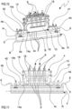
- Reference number 1 indicates a terminal employable for heating rails R during laying operations of the same rails R above railway ballast in order to allow laying and fixing in traction rails on the sleepers.
- the rails engaged with the sleepers when subjected to high temperature variations, are configured for being expanded or contracted by a reduced quantity, in a manner such to prevent possible breakage of the rails such to compromise the circulation of railway vehicles.
- the rail R is extended along an extension direction Y and has:
- each rail R may have:
- the terminal 1 allows the heating of the rails R due to Joule effect, serving for example a plurality of electrically power supplying conductive elements 3.
- the terminal 1 comprises a frame 4 carrying the conductive elements 3 and configured for positioning, in use, the conductive elements 3 in contact with the rail.
- the terminal 1 is configured for contacting a predetermined rail section, being positioned at least partially above the rail itself.
- the frame 4 comprises a base plate 14a extended along a longitudinal extension direction X between a first and a second end portion 4a, 4a to define a maximum extension length of the frame 4 greater than 400 mm, optionally comprised between 500 mm and 1000 mm.
- the base plate 14a defines a single rigid body extending in interposed between the first and the second end portion 4a, 4b and configured for being positioned, in use, above the top surface S of the rail.
- the frame 4 may also comprise a central body 4c defined in interposition between the first and the second end portion 4a, 4a, configured for engaging the conductive elements 3 with the frame 4.
- the frame 4 may also have a first and a second abutment element 41, 42 respectively defined at the first and at the second end portion 4a, 4a, which, in use, are configured for allowing the abutment of the terminal 1 on the top surface 6 of the rail R, as well as the movement of the terminal along the same rail R.
- the abutment elements 41, 42 allow the terminal to unload its weight on the rail; in this manner, the abovementioned conductive elements 3 are not thrust against the rail by the weight of the terminal, but are independently placed in contact with the rail by a thrust group 17, detailed below.
- the abutment elements 41, 42 are also configured for allowing the movement of the terminal along the rail section to be treated.
- each abutment element has a respective wheel which, in use, is configured for rolling on the top surface 6 of the rail R, allowing the sliding of the terminal 1 along the rail R.
- the wheels respectively of the first and of the second abutment element 41, 42, are configured for rotating about an axis orthogonal to the longitudinal extension direction of the frame, allowing the movement of the frame along the rail.
- the rotation axes of the wheels are parallel to each other and arranged at a distance greater than 300 m, optionally comprised between 400 mm and 1000 mm.
- each wheel of the first and of the second abutment element 41, 42 has an elongated cylindrical shape delimited by an external surface configured for contacting, in use, the top surface S of the rail.
- Each wheel also has, at end portions opposite each other along the rotation axis of the wheel itself, a flange, each of which configured for contacting the rail respectively at the first and of the second flank 7a, 7b of the same rail R, ensuring the sliding of the terminal along the extension direction Y of the rail section treated by the same terminal.
- each flange is extended along a direction radially exiting from the external surface of the same wheel, defining a contact portion with the rail.
- the first and the second abutment element 41, 42 have respective terminal elements integral with the base plate 14a and configured for carrying a wheel.
- the terminal elements have a hollow structure shaped as a parallelepiped, configured for housing a wheel at its interior which is free to rotate relative to the terminal element itself and simultaneously configured for protecting the wheel from possible impact with obstacles present on the railway ballast.
- the terminal 1 may also comprise at least one brush (not illustrated) carried by at least one of the first and the second abutment element 41, 42, configured for contacting the top surface 6 of the head H of the rail R and removing a surface layer of the same top surface 6 of the rail.
- the brush is configured for contacting and removing rust residues present on the upper surface 6 of the rail.
- Each contact element 3 is therefore configured for contacting the rail 6 following the removal of the surface layer of the same rail: the brush is then placed upstream of each conductive element along the advancement direction A of the railway vehicle.
- the removal of the surface layer of the rail prevents the damage of the top surface 6, since the contact between a conductive element 3 properly fed on a surface of the rail, e.g. having rust residues, may lead to the onset of sparks such to ruin the rail and compromise the passage of a railway vehicle.
- the removal of said surface layer allows the contact of each conductive element 3 on a smoothed surface, preventing the onset of sparks and consequently the damage of the rail.
- the terminal 1 may further comprise at least one guide element 5 carried by the frame 4 and configured, in use conditions of the terminal, for contacting the rail R and maintaining the frame 4 substantially parallel to the section of the rail R in contact with the terminal 1.
- the guide element 5 allows maintaining the frame 4, in use, in contact with the rail, allowing the sliding of the terminal parallel to the extension direction Y of the rail R.
- the guide element 5 is carried by the central body 4c of the frame, interposed between the first and the second end portion 4a, 4b and configured for contacting, in use, a connector surface of the rail R.
- the guide element comprises a contrast wheel movable via rotation about an axis substantially orthogonal to the longitudinal extension direction of the frame 4, relative to the central body 4c. The contrast wheel is thus configured for maintaining the terminal, in use, in contact with the rail, preventing possible movements of the terminal itself along a direction orthogonal to the longitudinal extension direction of the frame 4.
- the terminal comprises at least one first and a second guide element 5a, 5b respectively configured for contacting the first and the second flank 7a, 7b of the rail, for example at the first and second connector surfaces 8a, 8b.
- the first and the second guide element 5a, 5b substantially lie on a same plane orthogonal to the longitudinal extension direction X of the frame 4 and configured for being, in use conditions of the terminal 1, orthogonal to the advancement trajectory A.
- the first and the second guide element 5a, 5b, in a use condition of the terminal are configured for being arranged opposite each other with respect to a plane of symmetry of the transverse section of the rail R.
- the terminal 1 has a first and a second guide element 5a, 5b at the first end portion 4a of the terminal and a first and a second guide element at the second end portion 4b of the terminal.
- the guide elements placed at the first end portion 4a are spaced with respect to the guide elements arranged at the second end portion 4b by a quantity comprised between 400 mm and 1000 mm.
- the guide elements thus spaced along the longitudinal extension direction X of the frame 4 allow maintaining the entire frame 4 aligned along the extension direction Y of the rail section to be treated.
- the frame 4 may further comprise a support plate 13 relatively movable along a direction, in use, that is vertical close to and away from the base plate 14a.
- the support plate 13 carries directly or upon interposition of a thrust group 17 or of a sealing element 10 detailed below, the conductive elements 3.
- the support plate 13 allows, in use conditions, sets a distance that lies between each conductive element 3 and the rail R, allowing the same conductive elements to contact the rail R and allow the exchange of energy between the two.
- the support plate 13 in use, is movable close to and away from the rail, and thus allows overcoming the drawback concerning wear, due to the possibility of setting in place the distance between the conductive elements 3 and the rail R, ensuring the correct contact thereof.
- the support plate 13 has an elongated body extended along the longitudinal extension direction X between the first and the second end portion 4a, 4b.
- the terminal 1 may further comprise an adjustment device 14 carried by the frame 4 and engaged with the support plate 13, configured for moving the latter close to and away from the base plate 14a.
- the adjustment device 14 is directly carried by the base plate 14a and rigidly movable with the latter in use conditions of the terminal during which the latter is movable along the rail R; the adjustment device 14 thus allows the relative movement between the support plate 13 and the base plate 14a.
- the adjustment device 14 comprises at least one regulator 14b engaged with the base plate 14a and extended along a vertical direction away from the same base plate 14a, configured for slidably engaging the support plate 13 and moving it close to and away from the rail.
- the regulator 14b has an elongated body configured for being engaged within one or more holes of the support plate 13 and allowing the sliding of the same support plate along the elongated body of the regulator.
- the elongated body of the regulator 14b may have a threaded portion configured for being coupled, e.g. with a nut, configured for determining the relative position between the support plate 13 and the base plate 14a.
- the nut of the regulator 14b is placed coaxially with the elongated body of the regulator 14b, interposed between the support plate 13 and the base plate 14a: the relative movement between the nut and the elongated body consequently allows moving the support plate close to and away from the base plate 14a.
- the terminal 1 may have a respective regulator 14b engaged with the base plate 14a at the first and of the second end portion 4a, 4b of the frame 4.
- the base plate may thus have respective holes defined at opposite ends along the longitudinal extension direction of the frame 4, configured for being engaged with the respective regulators 14b.
- the terminal 1 may further have a top plate 27 carried by the frame 4 and rigidly engaged with the regulator 14b, configured for supporting a plurality of connectors 9 detailed below.
- the top plate 27 is extended along the longitudinal extension direction X of the frame, interposed between the first and the second end portion 4a, 4b.
- the top plate 27 may also have respective holes defined at opposite end portions with respect to the longitudinal extension direction X and configured for insertingly receiving a respective regulator 14b.
- the top plate faces the support plate 13: the support plate 13 is interposed between the base plate 14a and the top plate 27.
- the terminal may further comprise at least one connector 9 carried by the support plate 27 and configured for transmitting electrical energy to at least one conductive element 3.
- the connector 9 has at least one outlet configured for making an electrical connection between the terminal and a generator.
- the terminal comprises a plurality of connectors 9 arranged in parallel with each other and configured for power supplying a predetermined number of conductive elements equal to or lower than 3.
- Each connector 9 also comprises at least one cable 19 electrically interposed between the connector 9 and the predetermined number of conductive elements.
- each connector 9 comprises one or more cables 19, e.g. four, configured for connecting one or more conductive elements 3 to the generator 2.
- the connectors 9 may be placed electrically in parallel with each other, in a manner such to reduce the current transmitted to the single conductive elements. In this manner, it is possible to size the plurality of cables in a manner such that these have limited dimensions, that they are easily movable and not very bulky.
- the plurality of conductive elements 3, in use are configured for contacting the rail R and allowing a transfer of electrical energy between the terminal itself and the rail R.
- each conductive element 3 is carried by the frame 4 and configured for contacting the top surface 6 of the rail or at least one between the first and the second flank of the rail R.
- At least one part of the plurality of the conductive elements 3, in a use condition of the terminal 1 and during the movement of the latter along the extension direction Y of the rail R, is aligned along a direction parallel to the same extension direction Y of the rail R.
- the conductive elements 3 are configured for being arranged, in use, along a direction parallel to the extension direction X of the frame 4, contacting the rail on top of or on a flank. It is known that the conductive elements 3 are of a number greater than 2, optionally comprised between 3 and 30. Moreover, two conductive elements 3 adjacent to each other are spaced by a minimum distance greater than 3 mm, optionally comprised between 5 mm and 30 mm, in order to allow the dispersion of the heat and prevent an excessive overheating of the same conductive elements. With regard to the structure, each conductive element has a substantially rectangular parallelepiped conformation having a concave contact surface, which is configured for being arranged, in use, in contact with the rail.
- the contact surface is configured for having a conformation at least partly counter-shaped with respect to the top surface 6 or to the first or to the second flank 7a, 7b of the rail, in a manner such to allow a complete adhesion of the conductive element to the rail itself.
- the conductive elements 3 are made of conductive material, configured for transmitting energy to the rail, in particular, each conductive element 3 may be made of at least one of: graphite, coal-graphite, electro-graphite, metal-graphite, silver graphite, Bakelite graphite.
- the terminal 1 may further comprise at least one sealing element 10 carried by the frame 4 interposed between the first and the second guide element 5a, 5b and configured for engaging the plurality of conductive elements 3, maintaining them, in use conditions of the terminal, in contact with the rail.
- the sealing element may have a seat 12 configured for directly engaging the plurality of conductive elements and preventing a relative movement thereof with respect to the same sealing element 10.
- the sealing element 10 may be engaged with the central body 4c of the frame 4, e.g. by means of interposition of a thrust group 17 and is movable via rotation relative to said thrust group 17, in order to allow the movement of the conductive elements close to and away from the rail R. It is noted that the movement via rotation of the sealing element 10 is only possible during a condition of non-operation of the terminal, in which the latter is not coupled to the rail, while, in use, the sealing element 10 is configured for maintaining the conductive elements 3 in contact with at least one of the first and the second flank 7a, 7b of the head H of the rail R.
- the sealing element 10 is constrained to the top plate of the terminal upon interposition of a thrust group and is movable via rotation around an axis parallel to the extension direction X of the frame 4.
- the sealing element 10 may comprise a first and a second sealing element 10', 10", each of which carrying a plurality of conductive elements 3.
- the first and the second sealing element 10', 10" are movable via rotation around axes parallel to each other and parallel to the extension direction X of the frame: the first and the second sealing element 10', 10" are therefore movable via rotation close to and away from each other.
- the first and the second sealing element 10', 10" are configured for being arranged, in use, on the side of the rail in order to allow the respective plurality of conductive elements 3 to contact respectively the first and the second flank 7a, 7b of the rail.
- the first and the second sealing element 10', 10" are opposite each other with respect to a longitudinal center line plane of the terminal 1, which is substantially parallel to the longitudinal extension direction X of the frame 4 and orthogonal to the lying plane of the support plate 13.
- the conductive elements 3 are integral with the sealing element 10 and are, in use and during the movement of the terminal along the rail, slidingly movable relative to said rail R.
- conductive elements 3, in use define electrical sliding contacts configured for allowing the transfer of energy towards the rail R.
- Each sealing element 10 may have a casing ( figures 8 and 9 ) defining a compartment in which the plurality of conductive elements 3 is housed.
- the casing of the sealing element 10 lies on a plane substantially parallel to the lying plane of the support plate 13.
- the first and the second sealing element 10', 10" also comprise at least one respective catenary 18, each of which is configured for supporting and moving the plurality of conductive elements 3 at least during a use condition of the terminal.
- Each catenary 18 is also configured for arranging a first series 3' of conductive elements in direct contact with the rail R at the first and/or of the second flank 7a, 7b of the rail, as well as a second series 3" of conductive elements spaced from the rail.
- the first and the second series 3', 3" of conductive elements carry a respective plurality of conductive elements 3, which are movable as a closed loop along the catenary 18.
- each conductive element 3 is movable along the catenary, in use conditions of the terminal during which the latter is movable along the rail.
- the conductive elements 3 are thrust along the closed loop trajectory of the catenary 18 following the movement of the terminal along the rail.
- the conductive elements 3, are movable along the closed loop of the catenary following the contact between the same conductive elements and the rail, without the aid of a dedicated movement device, active on the catenary 18.
- the sealing element 10 may further comprise a plurality of commutators (not shown in the enclosed figures) housed within the casing of the same sealing element 10, electrically connected on one side to a respective connector 9 by means of the cables 19 and on the other side to a conductive element 3.
- each commutator is configured for contacting a respective conductive element 3, in order to allow the transfer of electrical energy towards the rail R.
- each commutator has a cylindrical body externally covered by sheets made of conductive material, configured for transmitting energy to the conductive elements.
- Each commutator 9 is also carried by the casing of the sealing element and is movable via rotation relative to the latter about a vertical axis.
- each commutator allows contacting the conductive elements 3 during the movement of the latter along the closed loop of the catenary 18, maintaining the position of the cables 19 fixed with respect to the top plate 27. In this manner, the commutators prevent the intertwining of the cables 19, which would be inevitable of integrally connected with a respective conductive element 3.
- the terminal 1 has a single sealing element 10 having a single catenary 18 arranged as a closed loop along a plane transverse to the lying plane of the support plate 13.
- the catenary 18 is configured for arranging a plurality of conductive elements in direct contact with the rail R at the top surface 6 of the head H of the rail R.
- the catenary allows the conductive elements 3 to contact the rail without sliding.
- the sealing element 10 is defined by the base plate 14a of the frame 4.
- the seat 12 is made directly on the base plate 14a with which the conductive elements 14 are engaged and aligned along the extension direction X of the frame 4.
- Such sealing element 10 is configured for arranging the plurality of conductive elements in direct contact with the rail R at the top surface 6 of the head H of the rail R.
- the conductive elements 3 are integral with the sealing element 10 and are, in use and during the movement of the terminal along the rail R, slidingly movable relative to the rail R. In other words, of the conductive elements 3, in use, define electrical sliding contacts configured for allowing the transfer of energy towards the rail R.
- the terminal may comprise a thrust group 17 configured for moving the sealing element 10 close to and away from the rail.
- the thrust group 17 may comprise:
- the pusher 17c is integrally carried by the support plate 13, configured for acting thrustingly on the arm and consequently on the sealing element 10, in order to move the latter close to and away from the rail.
- the at least one arm may comprise at least one first and one second arm 17a, 17b respectively hinged to the support plate 13 of the frame and opposite each other with respect to a longitudinal center line plane of the terminal which is substantially parallel to the longitudinal extension direction X of the frame 4 and orthogonal to the lying plane of the support plate 13.
- Each between the first and the second arm 17a, 17b is configured for maintaining in contact the conductive elements 3 carried by each sealing element 10', 10" respectively with the first and second flanks 7a, 7b of the rail R.
- the first and the second arm 17a, 17b are thus movable via rotation about respective axes that are parallel to each other and substantially parallel to the longitudinal extension direction X of the frame 4.
- the pusher 17c may comprise an actuator set for moving the first and the second arm 17a, 17b relative to the rail. It is possible to employ a hydraulic cylinder, or pneumatic cylinder or a helical spring.
- the thrust group 17 comprises at least one elastic return element 17d interposed between the support plate 13 and the plurality of conductive elements 3, configured for acting thrustingly on at least one conductive element 3 in order to force the contact between the latter and the rail R.
- the thrust group 17 comprises a plurality of elastic return elements 17d. Each elastic return element 17d is configured for ensuring the contact between a respective conductive element 3 on the upper surface S of the head H of the rail R.
- each elastic return element 17b is extended along a direction orthogonal to the upper surface S of the rail, configured for exerting a force on a respective conductive element directed orthogonally to the same upper surface S of the rail R.
- the elastic return elements 17d may in fact comprise a spring, e.g. compression spring.
- the apparatus 100 comprises at least one railway vehicle V movable on the railway ballast along an advancement trajectory A and configured for positioning at least one rail R above the same railway ballast.
- a railway vehicle is shown that is configured for traveling on rail and therefore usable for renovating pre-existing railway sections. It is possible to make a railway vehicle set for making a new movable railway line directly on the railway ballast, for example by means of the use of a tracked movement system.
- the apparatus 100 further comprises a generator 2 carried by the railway vehicle V and configured for supplying energy to be transmitted to the rail.
- the generator 2 may for example comprise an endothermic engine configured for generating mechanical energy, to which an alternator is connected that is configured for converting the mechanical energy of the endothermic generator into alternating voltage.
- the generator 2 may further comprise an electric power converter configured for converting the alternating voltage supplied by the alternator into direct voltage. It is in fact observed that it is preferable to power supply the rails with a direct voltage since this has a higher level of safety than alternating voltage, hence being less dangerous for personnel set for using the apparatus in case of malfunctions or accidents during the placement of the rails.
- the generator 2 may be configured for power supplying the terminal 1 in an intermittent manner.
- the generator 2 is configurable between:
- each terminal 1 is configured for being fixed with respect to the rail, while in the inactive condition, each terminal is configured for being movable relative to the rail R.
- the generator 2 is configured for operating in an intermittent manner, in other words, two temporally successive active conditions of the generator, are interrupted by an inactive condition.
- the active condition of the generator 2 may have a time duration different from the inactive condition; in particular, the active condition may have a time duration comprised between 2s and 600s, optionally comprised between 3s and 300s.
- the apparatus also comprises at least one terminal 1 according to the description above, carried by the railway vehicle and electrically connected to the generator 2, configured for contacting the rail and allowing the passage of current through said rail, allowing heating thereof due to Joule effect.
- the apparatus may comprise a first and a second terminal 1a, 1b carried by the railway vehicle and configured for contacting sections spaced from each other by a same rail.
- Each terminal 1a, 1b is connected to the generator 2 in order to define, in cooperation with the rail, a closed electric circuit.
- the first and the second terminal 1a, 1b, in use, are slidingly movable along a same rail R in order to deposit a new rail on the ballast.
- the first terminal 1a in use and during the movement of the apparatus along the ballast, is arranged upstream of the second terminal 1b with respect to the advancement trajectory A.
- the first terminal 1a in use, is thus arranged at a distance from the second terminal 1b greater than 10 meters, optionally comprised between 50 meters and 300 meters.
- the first and the second terminal 1a, 1b define a first connection group, configured for contacting a first rail 23a of a track heating thereof.
- the apparatus may further comprise first and second terminals 1a, 1b electrically connected to the generator 2 in order to define a second connection group, configured for contacting a second rail 23b of the track heating thereof.
- the first and the second connection group are electrically connected to the generator 2 in parallel, in a manner such to allow the passage, respectively on the first and second rails 23a, 23b, of a current having the same intensity, thus having an equivalent heating due to Joule effect of both the rails.
- the apparatus may also comprise a plurality of arms carried by the railway vehicle and configured for engaging a respective terminal.
- Each arm may be rigidly connected to the railway vehicle or at least partially movable via rotation relative to the latter.
- Each arm may also have a rigid or extensible body, e.g. in a telescopic manner.
- Each arm may in fact have:
- the hollow casing and the internal body may be movable relative to each other via sliding along an extension direction along which the same hollow casing and internal body are aligned.
- the apparatus may also comprise a plurality of actuators carried by the railway vehicle V, each of which active on a respective arm in order to move it relative to the railway vehicle V.
- each actuator allows the relative rotation of the respective arm with respect to the railway vehicle V, at least between:
- Each actuator may further comprise a respective position sensor configured for measuring an angular displacement between the extension direction of the arm on which the actuator is active and a rectilinear section of the railway vehicle parallel to the advancement direction A.
- the position sensor is configured for generating a signal representative of the angular displacement between the extension direction of the arm and the railway vehicle V and sending it to a control unit 50 detailed below.
- the railway vehicle may comprise a head wagon carrying first terminals 1a of the first and of the second group, an end wagon carrying seconds terminals 1b of the first and of the second group and one or more intermediate wagons for posing new rails and the picking up of old rails as detailed below. It is possible to make a single railway wagon to which the first and the seconds terminals 1a, 1b are connected, both of the first and second groups, at respective end portions.
- the apparatus may further comprise at least one removal device 20 carried by the railway vehicle V and configured for picking up old rails 21 from the railway ballast and depositing them on top of the railway vehicle, as well as at least one laying device 22 carried by the railway vehicle and configured for positioning a first and a second rail 23a, 23b on the railway ballast.
- the removal device 20 is arranged on the railway vehicle V upstream of the laying device 22 along the advancement direction A.
- the apparatus removes old rails 21, before laying and fixing the new rails 23a, 23b above sleepers.
- the removal device 20 and the laying device 22 are configured for operating, during the movement of the railway vehicle V along the ballast, both simultaneously with respect to each other and simultaneously with the heating of the rails.
- the laying device 22 is configured for laying and fixing the new rails 23a, 23b to the sleepers simultaneously with their heating executed by means of the terminals, attaining the abovementioned continuous laying.
- the apparatus may further comprise at least one temperature sensor 24 carried by the railway vehicle, for example by a support arm of a terminal, and active in proximity to a new rail to be laid.
- the temperature sensor 24 is configured for generating a signal representative of a temperature value of a rail in contact with a terminal 1.
- the apparatus comprises a plurality of temperature sensors 24, each of which active at a first and a second terminal 1a, 1b of the first and of the second group and configured for generating respective temperature signals representative of a heating temperature of the rail R.
- the apparatus may also comprise at least one control unit 50 connected to the railway vehicle V, to the generator 2 and to each temperature sensor 24, configured for:
- the control unit 50 is also configured for comparing the instantaneous estimated temperature value with a predetermined temperature value to which the rails may be heated and, as a function of said comparison, varying the advancement speed of the railway vehicle and/or varying the field voltages of the terminals. In such a manner, the control unit 50 is configured for continuously laying new rails, heating them at a constant temperature.
- the temperature sensor 24 is configured for operating at least in the active condition of the generator 2, allowing a uniform heating of the rails during the active condition of the generator 2.
- the control unit 50 may be active on the generator 2 in order to drive the passage thereof between the active condition and the inactive condition periodically, upon verification of an event or following the reception of a command signal.
- the control unit 50 is connected to the position sensor of each actuator of the arms and is configured for receiving the signal representative of the angular displacement of the arm with respect to the railway vehicle V.
- the control unit 50 may hence be configured for driving the passage between the active and inactive condition of the generator as a function of the signal representative of the angular displacement of the arm with respect to the railway vehicle V.
- the control unit 50 may be configured for driving the passage from the active condition to the inactive condition following the detection of at least one arm in the second end stop position.
- each terminal 1 is integral with the rail R, consequently each arm is rotationally moved with respect to the railway vehicle up to reaching the second end stop position, following the movement of the railway vehicle along the advancement trajectory A.
- the active actuators on a respective arm do not set any rotation of the arms themselves.
- each terminal 1 being maintained in contact with the rail R, is movable relative to the railway vehicle V, at a speed measured along the advancement trajectory A, greater than an advancement speed of the same railway vehicle V, which is measured along the advancement trajectory A.
- the ratio between the advancement speed of the terminal and the advancement speed of the railway vehicle is comprised between 0 and 1, optionally comprised between 0 and 0.8.
- the control unit 50 following the movement of each arm and of the relative terminal that took place in the inactive condition, is configured for driving the active condition of the generator 2 upon reaching the first end stop position of the arms themselves, once again allowing the heating of a further rail section R.
- the process provides for the positioning of one or more terminals 1 above a rail in a manner such that one or more of the conductive elements 3 may contact the rail (e.g. the top surface and/or a flank).
- the process provides for the positioning of at least two terminals engaged on the same rail.
- a first terminal is carried by a railway wagon (head engine), while the other of the two terminals is carried by an end wagon; the two terminals are spaced from each other along the railway ballast.
- the two terminals are electrically connected to respective poles of the generator.
- the railway vehicle advance along the railway ballast and the terminals engaged with the rail advance integrally with the railway vehicle, during the movement of the latter maintaining the conductive elements in contact with the rail, in a manner such that the latter may continuously transfer electrical energy to the rail.
- the railway vehicle advances along the ballast and simultaneously the control unit 50 drives the active condition of the generator 2; during the active condition, each terminal is fixed with respect to the rail while each arm in support of a respective terminal is moved from the first to the second end stop position.
- the control unit 50 drives the inactive condition of the generator 2, preventing the transmission of energy towards the rail.
- the control unit 50 drives each actuator active on a respective arm in order to move said arm from the second to the first end stop position; upon reaching the first end stop position, the control unit 50 is configured for newly driving the active condition of the generator, allowing the heating of a subsequent rail section R.
- the process may provide for the continuous laying of two rails for making a track. Furthermore, the process may simultaneously provide for laying the rails, a step of picking up the old rails and moving same on top of the railway vehicle for subsequent disposal.
- the structure of the terminal 1 ensures the correct contact of at least one conductive element with the rail, in a manner such that the terminal may - continuously and during the movement of the vehicle along the railway ballast - continuously transfer electrical energy to the rail, for the heating thereof due to Joule effect.
- the specific structure of the terminal prevents an excessive wear of the conductive elements, reducing to a minimum the maintenance interventions on the terminal and consequently reducing the times for laying the new railway section.
Landscapes
- Engineering & Computer Science (AREA)
- Architecture (AREA)
- Civil Engineering (AREA)
- Structural Engineering (AREA)
- Mechanical Engineering (AREA)
- Current-Collector Devices For Electrically Propelled Vehicles (AREA)
- Train Traffic Observation, Control, And Security (AREA)
- Electric Stoves And Ranges (AREA)
- Resistance Heating (AREA)
- Machines For Laying And Maintaining Railways (AREA)
Claims (15)
- Endgerät (1) für eine Vorrichtung (100) zum Verlegen mindestens einer Schiene (R) auf einem Eisenbahnschotter, wobei die Vorrichtung (100) umfasst:- mindestens ein Schienenfahrzeug (V), das auf dem Gleisschotter entlang einer Vorschubbahn (A) beweglich ist, wobei das Schienenfahrzeug (V) so konfiguriert ist, dass es mindestens eine besagte Schiene über demselben Eisenbahnschotter positioniert,- mindestens einen Generator (2), der von dem Schienenfahrzeug (V) getragen wird,wobei das Endgerät (1) mit dem Generator (2) verbindbar und mit der Schiene (R) in Eingriff bringbar ist, um den Durchgang von Strom durch besagte Schiene zu ermöglichen, wobei das Endgerät (1) in einem Eingriffszustand mit der Schiene in Bezug auf besagte Schiene entlang der Vorschubbahn (A) bewegbar ist, wobei das Endgerät eine Vielzahl von leitenden Elementen (3) umfasst, wobei mindestens eines der besagten leitenden Elemente (3) zum Kontaktieren der Schiene (R) konfiguriert ist, um die Schiene (R) in elektrische Verbindung mit dem Generator (2) zu setzen,dadurch gekennzeichnet, dass das Endgerät (1) einen Rahmen (4) umfasst, der die Vielzahl von leitenden Elementen (3) trägt, wobei sich der Rahmen (4) entlang einer longitudinalen Ausdehnungsrichtung (X) zwischen einem ersten und einem zweiten Endabschnitt (4a, 4a) erstreckt, wobei zwei oder mehr der leitenden Elemente (3) entlang einer Richtung im Wesentlichen parallel zu der longitudinalen Ausdehnungsrichtung (X) des Rahmens (4) ausgerichtet sind.
- Endgerät nach Anspruch 1, wobei jedes der leitenden Elemente (3) im Gebrauch so konfiguriert ist, dass es mindestens eine obere Fläche (6) und/oder eine Flanke der Schiene (R) berührt.
- Endgerät nach einem der vorhergehenden Ansprüche, wobei zwei oder mehr leitende Elemente (3) besagter Vielzahl im Gebrauch und während einer Bewegung des Endgeräts entlang einer Schiene entlang einer Richtung ausgerichtet sind, die so konfiguriert ist, dass sie im Wesentlichen parallel zu einem Abschnitt einer Ausdehnungsrichtung (Y) der Schiene (R) ist, über die das Endgerät (1) beweglich ist.
- Endgerät nach einem der vorhergehenden Ansprüche, wobei die Anzahl der leitenden Elemente (3) größer als 2 ist, optional umfassend zwischen 3 und 30.
- Endgerät nach einem der vorhergehenden Ansprüche, wobei die leitenden Elemente (3) entlang der Ausrichtungsrichtung beabstandet sind.
- Endgerät nach einem der vorhergehenden Ansprüche, wobei zwei unmittelbar aufeinanderfolgende leitende Elemente (3) entlang der Ausrichtungsrichtung in einem Mindestabstand von mehr als 3 mm platziert sind, optional umfassend zwischen 5 mm und 30 mm.
- Endgerät nach einem der vorhergehenden Ansprüche, wobei jedes leitende Element (3) aus mindestens einem der folgenden Materialien hergestellt ist mindestens einem der folgenden Materialien hergestellt ist: Graphit, Steinkohle, Kupfer, Bronze, Messing, optional ist jedes leitende Element zumindest teilweise aus mindestens einem der folgenden Materialien hergestellt: Kohle-Graphit, Elektro-Graphit, Metall-Graphit, Silber-Graphit, Bakelit-Graphit.
- Endgerät nach einem der vorhergehenden Ansprüche, wobei der Rahmen (4) einen zentralen Körper (4c) umfasst, der zwischen dem ersten und dem zweiten Endabschnitt (4a, 4b) eingeschoben ist, wobei die Vielzahl von leitenden Elementen (3) direkt mit dem zentralen Körper (4c) des Rahmens (4) in Eingriff steht.
- Endgerät nach einem der vorhergehenden Ansprüche, das mindestens ein erstes und ein zweites Auflagerelement (41, 42) umfasst, die im Gebrauch so konfiguriert sind, dass sie die Auflagerung des Endgeräts (1) selbst gegen eine obere Fläche (6) der Schiene (R) ermöglichen, wobei das erste und das zweite Auflagerelement (41, 42) jeweils ein Rad umfassen, das im Gebrauch so konfiguriert ist, dass es auf einer oberen Fläche (6) der Schiene (R) rollt, um das Gleiten des Endgeräts (1) entlang der Schiene (R) zu ermöglichen.
- Endgerät nach dem vorhergehenden Anspruch, wobei das erste und das zweite Auflagerelement (41, 42) am ersten bzw. zweiten Endabschnitt des Rahmens (4) platziert sind.
- Endgerät nach einem der vorhergehenden Ansprüche, der mindestens ein Dichtungselement (10) umfasst, das so konfiguriert ist, dass es mit der Vielzahl von leitenden Elementen (3) in Eingriff kommt, wobei das Dichtungselement (10) optional mit dem zentralen Körper (4c) des Rahmens (4) in Eingriff kommt, wobei der Rahmen (4) eine Stützplatte (13) umfasst, an die eine Schubgruppe (17) gepresst wird, die Schubgruppe (17) auch mit mindestens einem von dem Dichtungselement (10) und der Vielzahl von leitenden Elementen (3) in Eingriff steht, wobei die Schubgruppe (17) so konfiguriert ist, dass sie schiebend auf mindestens eines von dem Dichtungselement (10) und der Vielzahl von leitenden Elementen (3) wirkt, um den Kontakt zwischen einem oder mehreren der leitenden Elemente (3) mit der Schiene (R) zu erzwingen.
- Endgerät nach dem vorhergehenden Anspruch, wobei die Schubgruppe (17) umfasst:- mindestens einen Arm, welcher auf einer Seite an der Trägerplatte (13) des Rahmens (4) drehbar angebracht ist, während er auf der anderen Seite mit dem Dichtungselement (10) in Eingriff steht,- mindestens einen Schieber (17c), der auf besagtem Arm aktiv ist und so konfiguriert ist, dass er eines oder mehrere der leitenden Elemente (3), die von dem Dichtungselement (10) getragen werden, mit der Schiene in Kontakt hält, optional mit mindestens einem zwischen der ersten und der zweiten Flanke der Schiene.
- Vorrichtung (100) zum Verlegen von Schienen (R) auf einem Eisenbahnschotter, wobei besagte Vorrichtung umfasst:- mindestens ein Schienenfahrzeug (V), das auf dem Eisenbahnschotter entlang einer Vorschubbahn (A) beweglich ist, wobei das Schienenfahrzeug (V) so konfiguriert ist, dass es mindestens eine Schiene (R) über demselben Eisenbahnschotter positioniert,- mindestens einen Generator (2), der vom Schienenfahrzeug (V) getragen wird- mindestens ein Endgerät (1) nach einem der vorhergehenden Ansprüche, die mit dem Generator (2) verbunden ist und so konfiguriert ist, dass er die Schiene (R) kontaktiert, um den Durchgang von Strom durch die Schiene zu ermöglichen, wobei das Endgerät (1) mindestens ein erstes und ein zweites Endgerät (1a, 1b) umfasst, die elektrisch mit dem Generator (2) verbunden sind, um den Durchgang eines elektrischen Stroms durch besagte Schiene (R) zu ermöglichen, um deren Erhitzen zu ermöglichen, optional aufgrund des Joule-Effekts.
- Vorrichtung nach dem vorhergehenden Anspruch, umfassend:- ein erstes und ein zweites Endgerät (1a, 1b), die elektrisch mit dem Generator (2) verbunden sind, um eine erste Verbindungsgruppe zu definieren, wobei besagtes erstes und zweites Endgerät (1a, 1b) der ersten Verbindungsgruppe so konfiguriert sind, dass sie mit einer erste Schiene (23a) eines Gleises in Kontakt treten, wobei besagtes erstes und das zweite Endgerät (1a, 1b) der ersten Verbindungsgruppe in Kooperation mit dem Generator (2) so konfiguriert sind, dass sie den Durchgang eines elektrischen Stroms durch besagte erste Schiene (23a) ermöglichen, um deren Erhitzen zu ermöglichen,- ein erstes und ein zweites Endgerät (1a, 1b), die elektrisch mit dem Generator (2) verbunden sind, um eine zweite Verbindungsgruppe zu definieren, wobei besagtes erstes und zweites Endgerät (1a, 1b) der zweiten Verbindungsgruppe so konfiguriert sind, dass sie mit einer zweite Schiene (23b) eines Gleises in Kontakt treten, wobei besagtes erstes und zweites Endgerät (1a, 1b) der zweiten Verbindungsgruppe in Kooperation mit dem Generator (2) so konfiguriert sind, dass sie den Durchgang eines elektrischen Stroms durch die zweite Schiene (23b) ermöglichen, um deren Erhitzung zu erlauben.
- Vorrichtung nach Anspruch 13 oder 14, wobei der Generator (2) so konfiguriert ist, dass er einen aktiven Zustand definiert, während dem er besagtes Endgerät mit elektrischem Strom versorgt, wobei der Generator (2) so konfiguriert ist, dass er den aktiven Zustand während der Bewegung des Schienenfahrzeugs (V) entlang der Vorschubbahn definiert, wobei das Endgerät (1) während des aktiven Zustands des Generators und somit während der Bewegung des Schienenfahrzeugs (V) zusammen mit dem Schienenfahrzeug (V) beweglich ist, wobei optional das Schienenfahrzeug und das Endgerät während des aktiven Zustands des Generators entlang der Vorschubbahn (A) im Wesentlichen mit der gleichen Geschwindigkeit beweglich sind.
Applications Claiming Priority (1)
| Application Number | Priority Date | Filing Date | Title |
|---|---|---|---|
| IT102021000028691A IT202100028691A1 (it) | 2021-11-11 | 2021-11-11 | Terminale e relativa apparecchiatura per il riscaldamento di rotaie |
Publications (3)
| Publication Number | Publication Date |
|---|---|
| EP4180577A1 EP4180577A1 (de) | 2023-05-17 |
| EP4180577C0 EP4180577C0 (de) | 2024-07-24 |
| EP4180577B1 true EP4180577B1 (de) | 2024-07-24 |
Family
ID=79830976
Family Applications (1)
| Application Number | Title | Priority Date | Filing Date |
|---|---|---|---|
| EP22199437.9A Active EP4180577B1 (de) | 2021-11-11 | 2022-10-03 | Endgerät und zugehörige vorrichtung zum erwärmen von schienen |
Country Status (2)
| Country | Link |
|---|---|
| EP (1) | EP4180577B1 (de) |
| IT (1) | IT202100028691A1 (de) |
Families Citing this family (1)
| Publication number | Priority date | Publication date | Assignee | Title |
|---|---|---|---|---|
| IT202400007639A1 (it) * | 2024-04-05 | 2025-10-05 | Srt Soc A Responsabilita Limitata Con Socio Unico | Apparecchiatura per il riscaldamento di rotaie, procedimento di riscaldamento e posa di rotaie |
Family Cites Families (3)
| Publication number | Priority date | Publication date | Assignee | Title |
|---|---|---|---|---|
| AT307472B (de) | 1967-12-29 | 1973-05-25 | Plasser Bahnbaumasch Franz | Verfahren und Vorrichtung zum kontinuerlich fortschreitenden Verlegen von insbesondere aus stumpfgeschweißten Schienen gebildeten Schienensträngen |
| IT1268088B1 (it) | 1994-08-26 | 1997-02-20 | Bruno Faroldi | Apparecchiatura per il riscaldamento di rotaie durante la loro posa. |
| EP1223247A1 (de) * | 2001-01-11 | 2002-07-17 | Strukton Railinfra b.v. | Verfahren und Einrichtung zur Schienenvorspannung durch elektrische Erwärmung und Verfahren zum Einlegen von Schienen |
-
2021
- 2021-11-11 IT IT102021000028691A patent/IT202100028691A1/it unknown
-
2022
- 2022-10-03 EP EP22199437.9A patent/EP4180577B1/de active Active
Also Published As
| Publication number | Publication date |
|---|---|
| EP4180577A1 (de) | 2023-05-17 |
| EP4180577C0 (de) | 2024-07-24 |
| IT202100028691A1 (it) | 2023-05-11 |
Similar Documents
| Publication | Publication Date | Title |
|---|---|---|
| CN102770302B (zh) | 电动车辆充电站以及用于车辆的充电接收装置 | |
| EP4180577A1 (de) | Endgerät und zugehörige vorrichtung zum erwärmen von schienen | |
| US10744881B2 (en) | Positioning unit for a charging station and method for making contact | |
| CA2837923C (en) | Ice breaking pantograph | |
| KR102467861B1 (ko) | 전기차 충전을 위한 곡선 이동식 팬터그래프 자동 충전장치 | |
| CN109937154B (zh) | 用于车辆的集电器装置 | |
| CN101077567B (zh) | 用于接触轨的磨削装置及消除相邻接触轨末端偏差的方法 | |
| KR102129143B1 (ko) | 전기 이동 수단용 멀티 충전 장치 및 멀티 충전 방법 | |
| CN114829189A (zh) | 用于电力传输的集电器和方法 | |
| CN112188971B (zh) | 接触装置和快速充电系统 | |
| CN101304167B (zh) | 线缆热涨冷缩补偿装置 | |
| WO2016120263A1 (de) | Versorgungsschiene für ein kraftfahrzeug | |
| CN110126681A (zh) | 用于在停车中给可电运行的车辆充电的方法 | |
| DE102017117418A1 (de) | Primärseitige Ladevorrichtung, sekundärseitige Ladevorrichtung und Verfahren zum Laden einer Batterie für ein Fahrzeug mit einem elektrischen Antrieb | |
| WO2014207540A2 (en) | Overhead changing arrangement for a vehicle | |
| AU2019470169A1 (en) | Positioning unit for a charging station, and method for making contact | |
| JP2022532285A (ja) | 接触デバイス、車両、および充電ステーション | |
| JP7277482B2 (ja) | 軌道を走行可能な軌道整備用機械 | |
| KR20180024403A (ko) | 수직 순환형 주차장치 | |
| US12570168B2 (en) | Vehicle power supply system | |
| RU2784652C1 (ru) | Контактное устройство, транспортное средство и зарядная станция | |
| RU2798794C1 (ru) | Блок позиционирования для зарядной станции и способ контактирования | |
| RU2792044C2 (ru) | Контактный блок | |
| DE102024207804A1 (de) | Stromabnehmer und Fahrzeug mit einem solchen Stromabnehmer | |
| CN121515771A (zh) | 一种车辆的充电系统 |
Legal Events
| Date | Code | Title | Description |
|---|---|---|---|
| PUAI | Public reference made under article 153(3) epc to a published international application that has entered the european phase |
Free format text: ORIGINAL CODE: 0009012 |
|
| STAA | Information on the status of an ep patent application or granted ep patent |
Free format text: STATUS: THE APPLICATION HAS BEEN PUBLISHED |
|
| AK | Designated contracting states |
Kind code of ref document: A1 Designated state(s): AL AT BE BG CH CY CZ DE DK EE ES FI FR GB GR HR HU IE IS IT LI LT LU LV MC ME MK MT NL NO PL PT RO RS SE SI SK SM TR |
|
| P01 | Opt-out of the competence of the unified patent court (upc) registered |
Effective date: 20230518 |
|
| STAA | Information on the status of an ep patent application or granted ep patent |
Free format text: STATUS: REQUEST FOR EXAMINATION WAS MADE |
|
| 17P | Request for examination filed |
Effective date: 20231102 |
|
| RBV | Designated contracting states (corrected) |
Designated state(s): AL AT BE BG CH CY CZ DE DK EE ES FI FR GB GR HR HU IE IS IT LI LT LU LV MC ME MK MT NL NO PL PT RO RS SE SI SK SM TR |
|
| GRAP | Despatch of communication of intention to grant a patent |
Free format text: ORIGINAL CODE: EPIDOSNIGR1 |
|
| STAA | Information on the status of an ep patent application or granted ep patent |
Free format text: STATUS: GRANT OF PATENT IS INTENDED |
|
| INTG | Intention to grant announced |
Effective date: 20240223 |
|
| RIN1 | Information on inventor provided before grant (corrected) |
Inventor name: SALCICCIA, GILBERTO Inventor name: ROSSANIGO, CESARE |
|
| GRAS | Grant fee paid |
Free format text: ORIGINAL CODE: EPIDOSNIGR3 |
|
| GRAA | (expected) grant |
Free format text: ORIGINAL CODE: 0009210 |
|
| STAA | Information on the status of an ep patent application or granted ep patent |
Free format text: STATUS: THE PATENT HAS BEEN GRANTED |
|
| AK | Designated contracting states |
Kind code of ref document: B1 Designated state(s): AL AT BE BG CH CY CZ DE DK EE ES FI FR GB GR HR HU IE IS IT LI LT LU LV MC ME MK MT NL NO PL PT RO RS SE SI SK SM TR |
|
| REG | Reference to a national code |
Ref country code: GB Ref legal event code: FG4D |
|
| REG | Reference to a national code |
Ref country code: CH Ref legal event code: EP |
|
| REG | Reference to a national code |
Ref country code: IE Ref legal event code: FG4D Ref country code: DE Ref legal event code: R096 Ref document number: 602022004788 Country of ref document: DE |
|
| U01 | Request for unitary effect filed |
Effective date: 20240724 |
|
| U07 | Unitary effect registered |
Designated state(s): AT BE BG DE DK EE FI FR IT LT LU LV MT NL PT SE SI Effective date: 20240806 |
|
| P04 | Withdrawal of opt-out of the competence of the unified patent court (upc) registered |
Free format text: CASE NUMBER: APP_44895/2024 Effective date: 20240802 |
|
| U20 | Renewal fee for the european patent with unitary effect paid |
Year of fee payment: 3 Effective date: 20241025 |
|
| P05 | Withdrawal of opt-out of the competence of the unified patent court (upc) changed |
Free format text: CASE NUMBER: APP_44895/2024 Effective date: 20240806 |
|
| PG25 | Lapsed in a contracting state [announced via postgrant information from national office to epo] |
Ref country code: NO Free format text: LAPSE BECAUSE OF FAILURE TO SUBMIT A TRANSLATION OF THE DESCRIPTION OR TO PAY THE FEE WITHIN THE PRESCRIBED TIME-LIMIT Effective date: 20241024 |
|
| PG25 | Lapsed in a contracting state [announced via postgrant information from national office to epo] |
Ref country code: PL Free format text: LAPSE BECAUSE OF FAILURE TO SUBMIT A TRANSLATION OF THE DESCRIPTION OR TO PAY THE FEE WITHIN THE PRESCRIBED TIME-LIMIT Effective date: 20240724 Ref country code: GR Free format text: LAPSE BECAUSE OF FAILURE TO SUBMIT A TRANSLATION OF THE DESCRIPTION OR TO PAY THE FEE WITHIN THE PRESCRIBED TIME-LIMIT Effective date: 20241025 |
|
| PG25 | Lapsed in a contracting state [announced via postgrant information from national office to epo] |
Ref country code: IS Free format text: LAPSE BECAUSE OF FAILURE TO SUBMIT A TRANSLATION OF THE DESCRIPTION OR TO PAY THE FEE WITHIN THE PRESCRIBED TIME-LIMIT Effective date: 20241124 |
|
| PG25 | Lapsed in a contracting state [announced via postgrant information from national office to epo] |
Ref country code: HR Free format text: LAPSE BECAUSE OF FAILURE TO SUBMIT A TRANSLATION OF THE DESCRIPTION OR TO PAY THE FEE WITHIN THE PRESCRIBED TIME-LIMIT Effective date: 20240724 |
|
| PG25 | Lapsed in a contracting state [announced via postgrant information from national office to epo] |
Ref country code: RS Free format text: LAPSE BECAUSE OF FAILURE TO SUBMIT A TRANSLATION OF THE DESCRIPTION OR TO PAY THE FEE WITHIN THE PRESCRIBED TIME-LIMIT Effective date: 20241024 Ref country code: ES Free format text: LAPSE BECAUSE OF FAILURE TO SUBMIT A TRANSLATION OF THE DESCRIPTION OR TO PAY THE FEE WITHIN THE PRESCRIBED TIME-LIMIT Effective date: 20240724 |
|
| PG25 | Lapsed in a contracting state [announced via postgrant information from national office to epo] |
Ref country code: RS Free format text: LAPSE BECAUSE OF FAILURE TO SUBMIT A TRANSLATION OF THE DESCRIPTION OR TO PAY THE FEE WITHIN THE PRESCRIBED TIME-LIMIT Effective date: 20241024 Ref country code: PL Free format text: LAPSE BECAUSE OF FAILURE TO SUBMIT A TRANSLATION OF THE DESCRIPTION OR TO PAY THE FEE WITHIN THE PRESCRIBED TIME-LIMIT Effective date: 20240724 Ref country code: NO Free format text: LAPSE BECAUSE OF FAILURE TO SUBMIT A TRANSLATION OF THE DESCRIPTION OR TO PAY THE FEE WITHIN THE PRESCRIBED TIME-LIMIT Effective date: 20241024 Ref country code: IS Free format text: LAPSE BECAUSE OF FAILURE TO SUBMIT A TRANSLATION OF THE DESCRIPTION OR TO PAY THE FEE WITHIN THE PRESCRIBED TIME-LIMIT Effective date: 20241124 Ref country code: HR Free format text: LAPSE BECAUSE OF FAILURE TO SUBMIT A TRANSLATION OF THE DESCRIPTION OR TO PAY THE FEE WITHIN THE PRESCRIBED TIME-LIMIT Effective date: 20240724 Ref country code: GR Free format text: LAPSE BECAUSE OF FAILURE TO SUBMIT A TRANSLATION OF THE DESCRIPTION OR TO PAY THE FEE WITHIN THE PRESCRIBED TIME-LIMIT Effective date: 20241025 Ref country code: ES Free format text: LAPSE BECAUSE OF FAILURE TO SUBMIT A TRANSLATION OF THE DESCRIPTION OR TO PAY THE FEE WITHIN THE PRESCRIBED TIME-LIMIT Effective date: 20240724 |
|
| PG25 | Lapsed in a contracting state [announced via postgrant information from national office to epo] |
Ref country code: SM Free format text: LAPSE BECAUSE OF FAILURE TO SUBMIT A TRANSLATION OF THE DESCRIPTION OR TO PAY THE FEE WITHIN THE PRESCRIBED TIME-LIMIT Effective date: 20240724 Ref country code: RO Free format text: LAPSE BECAUSE OF FAILURE TO SUBMIT A TRANSLATION OF THE DESCRIPTION OR TO PAY THE FEE WITHIN THE PRESCRIBED TIME-LIMIT Effective date: 20240724 |
|
| PG25 | Lapsed in a contracting state [announced via postgrant information from national office to epo] |
Ref country code: CZ Free format text: LAPSE BECAUSE OF FAILURE TO SUBMIT A TRANSLATION OF THE DESCRIPTION OR TO PAY THE FEE WITHIN THE PRESCRIBED TIME-LIMIT Effective date: 20240724 |
|
| PG25 | Lapsed in a contracting state [announced via postgrant information from national office to epo] |
Ref country code: SK Free format text: LAPSE BECAUSE OF FAILURE TO SUBMIT A TRANSLATION OF THE DESCRIPTION OR TO PAY THE FEE WITHIN THE PRESCRIBED TIME-LIMIT Effective date: 20240724 |
|
| PLBE | No opposition filed within time limit |
Free format text: ORIGINAL CODE: 0009261 |
|
| STAA | Information on the status of an ep patent application or granted ep patent |
Free format text: STATUS: NO OPPOSITION FILED WITHIN TIME LIMIT |
|
| 26N | No opposition filed |
Effective date: 20250425 |
|
| PG25 | Lapsed in a contracting state [announced via postgrant information from national office to epo] |
Ref country code: MC Free format text: LAPSE BECAUSE OF FAILURE TO SUBMIT A TRANSLATION OF THE DESCRIPTION OR TO PAY THE FEE WITHIN THE PRESCRIBED TIME-LIMIT Effective date: 20240724 |
|
| PG25 | Lapsed in a contracting state [announced via postgrant information from national office to epo] |
Ref country code: IE Free format text: LAPSE BECAUSE OF NON-PAYMENT OF DUE FEES Effective date: 20241003 |
|
| REG | Reference to a national code |
Ref country code: CH Ref legal event code: U11 Free format text: ST27 STATUS EVENT CODE: U-0-0-U10-U11 (AS PROVIDED BY THE NATIONAL OFFICE) Effective date: 20251101 |
|
| U20 | Renewal fee for the european patent with unitary effect paid |
Year of fee payment: 4 Effective date: 20251027 |
|
| PGFP | Annual fee paid to national office [announced via postgrant information from national office to epo] |
Ref country code: CH Payment date: 20251101 Year of fee payment: 4 |
|
| PG25 | Lapsed in a contracting state [announced via postgrant information from national office to epo] |
Ref country code: CY Free format text: LAPSE BECAUSE OF FAILURE TO SUBMIT A TRANSLATION OF THE DESCRIPTION OR TO PAY THE FEE WITHIN THE PRESCRIBED TIME-LIMIT; INVALID AB INITIO Effective date: 20221003 |
|
| PG25 | Lapsed in a contracting state [announced via postgrant information from national office to epo] |
Ref country code: HU Free format text: LAPSE BECAUSE OF FAILURE TO SUBMIT A TRANSLATION OF THE DESCRIPTION OR TO PAY THE FEE WITHIN THE PRESCRIBED TIME-LIMIT; INVALID AB INITIO Effective date: 20221003 |
|
| PG25 | Lapsed in a contracting state [announced via postgrant information from national office to epo] |
Ref country code: TR Free format text: LAPSE BECAUSE OF FAILURE TO SUBMIT A TRANSLATION OF THE DESCRIPTION OR TO PAY THE FEE WITHIN THE PRESCRIBED TIME-LIMIT Effective date: 20240724 |
|
| PG25 | Lapsed in a contracting state [announced via postgrant information from national office to epo] |
Ref country code: ME Free format text: LAPSE BECAUSE OF FAILURE TO SUBMIT A TRANSLATION OF THE DESCRIPTION OR TO PAY THE FEE WITHIN THE PRESCRIBED TIME-LIMIT Effective date: 20240724 |