EP4180542A1 - Method for refining molten steel - Google Patents
Method for refining molten steel Download PDFInfo
- Publication number
- EP4180542A1 EP4180542A1 EP21836922.1A EP21836922A EP4180542A1 EP 4180542 A1 EP4180542 A1 EP 4180542A1 EP 21836922 A EP21836922 A EP 21836922A EP 4180542 A1 EP4180542 A1 EP 4180542A1
- Authority
- EP
- European Patent Office
- Prior art keywords
- molten steel
- vacuum tank
- immersion tube
- vacuum
- circulating gas
- Prior art date
- Legal status (The legal status is an assumption and is not a legal conclusion. Google has not performed a legal analysis and makes no representation as to the accuracy of the status listed.)
- Pending
Links
Images



Classifications
-
- C—CHEMISTRY; METALLURGY
- C21—METALLURGY OF IRON
- C21C—PROCESSING OF PIG-IRON, e.g. REFINING, MANUFACTURE OF WROUGHT-IRON OR STEEL; TREATMENT IN MOLTEN STATE OF FERROUS ALLOYS
- C21C7/00—Treating molten ferrous alloys, e.g. steel, not covered by groups C21C1/00 - C21C5/00
- C21C7/10—Handling in a vacuum
-
- C—CHEMISTRY; METALLURGY
- C21—METALLURGY OF IRON
- C21C—PROCESSING OF PIG-IRON, e.g. REFINING, MANUFACTURE OF WROUGHT-IRON OR STEEL; TREATMENT IN MOLTEN STATE OF FERROUS ALLOYS
- C21C7/00—Treating molten ferrous alloys, e.g. steel, not covered by groups C21C1/00 - C21C5/00
- C21C7/0075—Treating in a ladle furnace, e.g. up-/reheating of molten steel within the ladle
-
- C—CHEMISTRY; METALLURGY
- C21—METALLURGY OF IRON
- C21C—PROCESSING OF PIG-IRON, e.g. REFINING, MANUFACTURE OF WROUGHT-IRON OR STEEL; TREATMENT IN MOLTEN STATE OF FERROUS ALLOYS
- C21C7/00—Treating molten ferrous alloys, e.g. steel, not covered by groups C21C1/00 - C21C5/00
- C21C7/04—Removing impurities by adding a treating agent
- C21C7/068—Decarburising
-
- C—CHEMISTRY; METALLURGY
- C21—METALLURGY OF IRON
- C21C—PROCESSING OF PIG-IRON, e.g. REFINING, MANUFACTURE OF WROUGHT-IRON OR STEEL; TREATMENT IN MOLTEN STATE OF FERROUS ALLOYS
- C21C7/00—Treating molten ferrous alloys, e.g. steel, not covered by groups C21C1/00 - C21C5/00
- C21C7/04—Removing impurities by adding a treating agent
- C21C7/072—Treatment with gases
Definitions
- the present invention relates to a molten steel refining method using an RH vacuum degassing apparatus.
- an RH vacuum degassing apparatus 1 has a rising-side immersion tube 8 and a descending-side immersion tube 9. These rising-side immersion tube 8 and descending-side immersion tube 9 are immersed into molten steel 3 inside a ladle 2, and the inside of a degassing vacuum tank 5 is depressurized by discharging air from a discharge port through a duct 11 by a depressurization device (not shown) to thereby suck up the molten steel 3. Then, a circulating gas is blown into the rising-side immersion tube 8 including a circulating gas blow-in pipe 10 through this circulating gas blow-in pipe 10. As the circulating gas, an inert gas, such as an argon gas, is often used. The molten steel 3 is moved upward using the gas buoyancy and led to the degassing vacuum tank 5, and is then moved downward through the descending-side immersion tube 9. Thus, the molten steel 3 is circulated and degassed.
- an inert gas such as an argon gas
- Examples of refining using such an RH vacuum degassing apparatus include decarburization under vacuum (hereinafter referred to as "vacuum decarburization") and degassing of hydrogen, nitrogen, etc.
- vacuum decarburization decarburization under vacuum
- Increasing the circulating rate is effective for accelerating the decarburization speed in vacuum decarburization or the degassing speed in degassing, and many methods for increasing the circulating rate have been proposed.
- Patent Literature 1 proposes a method in which an inert gas having been heated to 200 °C to 1000 °C is blown in at a pressure of 0.5 MPa or higher to circulate molten steel.
- Patent Literature 2 proposes a method in which a degassing tank is extended downward to provide an outer immersion tube opening downward, and inside this outer immersion tube, an inner immersion tube opening upward and downward is concentrically disposed to serve as a rising flow passage through which molten steel rises as an argon gas is blown in from a circulating gas blow-in nozzle provided in the inner immersion tube, while the gap between the inner immersion tube and the outer immersion tube serves as a descending flow passage for the molten steel.
- the rising flow passage and the descending flow passage with large cross-sectional areas are formed to thereby increase the circulating rate of the molten steel.
- the circulating rate in a degassing apparatus is calculated by the following Formula (A) disclosed in Non Patent Literature 1:
- Qc K ⁇ G 1 / 3 ⁇ D 4 / 3 ⁇ ln P 0 / P 1 / 3 / ⁇ 1 / 1000
- Qc calculated molten steel circulating rate (molten steel m 3 /min)
- G circulating gas flow rate (Nm 3 /sec)
- D inside diameter (m) of immersion tube
- P pressure (Pa) inside vacuum tank
- P 0 atmospheric pressure (101325 Pa)
- ⁇ 1 density (kg/m 3 ) of molten steel.
- K is a fitting parameter that is obtained from results of experiments under various operation conditions, and Non Patent Literature 2 reports that K is approximately 446.3 under molten steel conditions.
- the power index of the inside diameter D of the immersion tube is higher than that of the circulating gas flow rate G. This indicates that, to increase the calculated molten steel circulating rate Qc, increasing the inside diameter of the immersion tube is more effective than increasing the circulating gas flow rate. It is generally known that increasing the inside diameter of the immersion tube and thereby increasing the circulating rate of molten steel is effective as means for enhancing the efficiency of the degassing reaction.
- the inside diameter of the immersion tube is restricted by the size of the degassing tank, so that increasing the inside diameter of the immersion tube in most cases requires expanding the degassing gas tank at the same time.
- the dimensions of the degassing tank are restricted by the size of ladle and ancillary facilities. Therefore, when it is difficult for facility reasons to evenly expand the degassing tank while keeping its exact circular shape, a technique is used such as forming the degassing tank in an elliptic shape by expanding it only in the circulation direction, i.e., the direction from the rising tube toward the descending tube, and expanding the immersion tube so as to correspond to the expansion in a long-axis direction of the elliptic shape.
- Patent Literature 3 proposes a structure of a degassing tank that is elliptic in lateral cross-section and has a pair of circulation tubes arranged in a long-axis direction. According to this literature, performing vacuum refining using a degassing tank adopting this technique can eliminate a stagnant part in a molten steel flow inside the vacuum degassing tank and thereby preclude the standstill of molten steel and the retention of slag, so that the decarburization speed increases.
- Patent Literature 4 proposes a method that fines air bubbles of an inert gas by providing an ultrasonic vibrator on an inner circumferential surface of a rising-side immersion tube, above an installation position of a circulating gas blow-in pipe provided in the rising-side immersion tube.
- Patent Literature 1 has a problem in that it needs equipment for preheating an inert gas and thereby causes an increase in the treatment cost.
- Patent Literature 2 has a problem in that, as it needs the outer immersion tube and the inner immersion tube, the device becomes complicated. Moreover, the circulating gas pipe needs to be passed to the inner immersion tube via the degassing tank, which makes it impossible to replace only the inner immersion tube by removing it from the degassing tank. Thus, replacing the immersion tube requires replacing the whole lower degassing tank, so that the refractory cost increases significantly.
- Patent Literature 3 has a problem in that it takes considerable time and money to introduce, as forming a degassing tank into an elliptic structure requires newly producing an iron shell of the degassing tank.
- Patent Literature 4 needs the ultrasonic vibrator, an ultrasonic wave transmitter, etc., so that not only does the device become complicated but also an increase in the device cost and the immersion tube cost is unavoidable.
- the present invention aims to propose a molten steel refining method that can increase the circulating rate when refining molten steel using an RH vacuum degassing apparatus, without requiring new facility investment or causing an increase in the treatment cost.
- the present inventors conducted various experiments with attention focused on the influence of operation conditions and the shape of an RH vacuum degassing apparatus on a flow inside a degassing tank. As a result, we found that the energy of a circulating gas blown into a rising tube was dissipated mainly inside a vacuum tank bath, and that changing the operation conditions so as to reduce the amount of energy dissipated could increase the circulating rate.
- the present invention has been contrived based on this finding, and the gist thereof is as follows.
- a molten steel refining method of the present invention that advantageously solves the above problems is a molten steel refining method using an RH vacuum degassing apparatus, characterized in that an immersion depth l of an immersion tube into molten steel inside a vacuum tank or a circulating gas flow rate G is determined such that a stirring power energy density ⁇ for the molten steel expressed by the following Formulae (1) to (4) meets the following Formula (5).
- Formulae (1) to (4) meets the following Formula (5).
- ⁇ the stirring power energy density (watt/ton) for the molten steel inside the vacuum tank
- G the circulating gas flow rate (Nm 3 /sec)
- T a temperature (K) of the molten steel
- ⁇ L a density (kg/m 3 ) of the molten steel
- g a gravitational acceleration (9.8 m/sec 2 )
- Wv a mass (ton) of the molten steel inside the vacuum tank
- Dv an inside diameter (m) of the vacuum tank
- H 0 a height (m) from a position of a circulating gas blow-in nozzle to a bath surface of the molten steel inside the vacuum tank in a stationary state
- P a pressure (Pa) inside the vacuum tank
- P 0 an atmospheric pressure (101325 Pa)
- hv a height (m) from the bath surface of the molten steel inside the vacuum tank in the stationary state to a bed
- L a height (m) from a lower end of the immersion
- the molten steel refining method according to the present invention could be a more preferable solution when the immersion depth l of the immersion tube into the molten steel or the circulating gas flow rate G is determined such that the stirring power energy density ⁇ meets the following Formula (6): 1.35 ⁇ 10 5 ⁇ D U / W V ⁇ ⁇ ⁇ 1.0 ⁇ 10 4
- the present invention can increase the circulating rate and contributes to shortening the treatment time when refining molten steel using an RH vacuum degassing apparatus, without requiring new facility investment or causing an increase in the treatment cost.
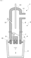
- FIG. 1 is a schematic vertical sectional view showing one example of an RH vacuum degassing apparatus used for a molten steel refining method as one embodiment of the present invention.
- reference sign 1 is an RH vacuum degassing apparatus; 2 is a ladle; 3 is molten steel; 4 is slag; 5 is a vacuum tank; 6 is an upper tank; 7 is a lower tank; 8 is a rising-side immersion tube (rising tube); 9 is a descending-side immersion tube (descending tube); 10 is a circulating gas blow-in pipe; 11 is a duct; 12 is a raw material charging port; and 13 is a top-blowing lance.
- the vacuum tank 5 is composed of the upper tank 6 and the lower tank 7.
- the top-blowing lance 13 is a device through which an oxygen gas or a solvent is blown to be added to the molten steel inside the vacuum tank, and is installed at an upper part of the vacuum tank 5 while being able to move up and down inside the vacuum tank 5.
- the ladle 2 containing the molten steel 3 is raised by a raising-lowering device (not shown), and the rising-side immersion tube 8 and the descending-side immersion tube 9 are immersed into the molten steel 3 inside the ladle. Then, air inside the vacuum tank 5 is discharged by an exhaust device (not shown) coupled to the duct 11 to depressurize the inside of the vacuum tank 5, and a circulating gas is blown into the rising-side immersion tube 8 through the circulating gas blow-in pipe 10.
- the inside of the vacuum tank 5 is depressurized, the molten steel 3 inside the ladle rises in proportion to the difference between an atmospheric pressure and a pressure (a degree of vacuum) inside the vacuum tank and flows into the vacuum tank.
- the molten steel 3 rises through the rising-side immersion tube 8 along with the circulating gas and flows into the vacuum tank 5. Thereafter, the molten steel 3 forms a flow that returns to the ladle 2 via the descending-side immersion tube 9, or a so-called circulating flow, and thus undergoes refining by RH vacuum degassing. As the molten steel 3 is exposed to a depressurized atmosphere inside the vacuum tank, gas components in the molten steel move to the atmosphere inside the vacuum tank and a degassing reaction of the molten steel 3 progresses.
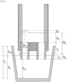
- FIG. 2 is an enlarged sectional view of the RH vacuum degassing apparatus representing the concept of the present invention.
- the symbols relating to the dimensions of the RH vacuum degassing apparatus used in the above Formulae (1) to (4) are indicated.
- FIG. 3 shows a relationship of a standardized circulating rate with the stirring power energy density ⁇ for the fluid inside the vacuum tank in the water model experiment.
- the standardized circulating rate is a ratio relative to a value at which the circulating rate is lowest.
- the reason why the circulating rate varies as described above is as follows: when the stirring power energy density ⁇ for the molten steel inside the vacuum tank is lower, there is less stirring of the bath surface and the ratio of energy consumed as energy that fluctuates the boundary of the molten steel becomes lower, so that the ratio of a part of the energy of the circulating gas that contributes to circulation increases proportionally and thus the circulating rate increases.
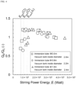
- FIG. 4 shows a relationship between the stirring power energy E and Q E /Q C that is a ratio of the actually measured molten steel circulating rate Q E (molten steel m 3 /min) to the calculated molten steel circulating rate Qc obtained using Formula (A) in RH vacuum degassing apparatuses varying in an immersion tube diameter and a vacuum tank inside diameter.
- Q E molten steel circulating rate
- Qc calculated molten steel circulating rate
- FIG. 5 shows a relationship between the rising tube diameter Du and E min , with E min defined as the minimum stirring power energy. From a proportional constant in proportional approximation of the relationship between the rising tube diameter Du and E min obtained from the relationship of FIG. 5 , a condition for the stirring power energy E required for normal circulation in the RH vacuum degassing apparatus was defined as expressed by the following Formula (7): 1.35 ⁇ 10 5 ⁇ D U ⁇ E
- Formula (7) is transformed into the following Formula (8): 1.35 ⁇ 10 5 ⁇ D U / W V ⁇ ⁇
- FIG. 6 shows the relationship between the stirring power energy density ⁇ for the molten steel inside the vacuum tank and Q E /Q C . In FIG. 6 , those conditions that do not meet Formula (8) are omitted.
- Formula (9) is obtained as a condition for ⁇ that increases the circulating rate: ⁇ ⁇ 2.1 ⁇ 10 4
- Formula (5) is obtained as a condition for the stirring power energy density ⁇ required to increase the energy efficiency of the circulating gas and increase the circulating rate: 1.35 ⁇ 10 5 ⁇ D U / W V ⁇ ⁇ ⁇ 2.1 ⁇ 10 4
- Parameters for controlling the stirring power energy density ⁇ inside the vacuum tank to be within the range of Formula (5) or Formula (6) are the circulating gas flow rate G, the degree of vacuum P, and the immersion depth l of the immersion tube into the molten steel, other than the dimensions of the apparatus.
- the degree of vacuum is degraded, the reaction speed of degassing that is the original purpose decreases or becomes zero. Therefore, it is desirable to perform control by changing the circulating gas flow rate G or the immersion depth l of the immersion tube into the molten steel.
- the present invention can increase the circulating rate of molten steel without requiring new equipment investment or causing an increase in the treatment cost.
- Vacuum refining of 300 tons of molten steel that had been blown by a converter was performed using an RH vacuum degassing apparatus.
- ⁇ was calculated by Formulae (1) to (4) from the dimensions of the apparatus and operation conditions, and the immersion depth l of the immersion tube into the molten steel was adjusted within a range of 0.3 m to 0.9 m so as to meet Formula (5) or Formula (6).
- a degassing tank (tank A) having the vacuum tank cross-sectional area S A of 3.14 m 2 and the rising tube inside diameter Du of 0.6 m, or the degassing tank (tank B) having a vacuum tank cross-sectional area S A of 3.8 m 2 and the rising tube inside diameter Du of 0.8 m was used.
- the degree of vacuum P was 133 Pa
- the circulating gas flow rate G was held constant at the flow rate of one of 0.020 Nm 3 /sec, 0.027 Nm 3 /sec, 0.037 Nm 3 /sec, and 0.050 Nm 3 /sec during treatment.
- the calculated molten steel circulating rate Qc was obtained using Formula (A), and Q E /Q C was calculated for each charge.
- the constant K in Formula (A) was set to 446.3.
- the molten steel used had an element composition with C: 0.04 to 0.06 mass%, Si: 0.05 mass% or less, Mn: 0.3 mass% or less, P: 0.02 mass% or less, and S: 0.003 mass% or less, and the temperature of the molten steel before treatment was 1640 to 1670 °C.
- the molten steel refining method of the present invention can optimize the circulating rate in an RH vacuum degassing apparatus and thereby efficiently perform vacuum decarburization or vacuum degassing, which makes it useful for industrial purposes.
Landscapes
- Chemical & Material Sciences (AREA)
- Engineering & Computer Science (AREA)
- Materials Engineering (AREA)
- Metallurgy (AREA)
- Organic Chemistry (AREA)
- Treatment Of Steel In Its Molten State (AREA)
Abstract
Description
- The present invention relates to a molten steel refining method using an RH vacuum degassing apparatus.
- Various types of means for performing ladle refining and vacuum degassing of molten steel are known, including VOD and VTD. With steel materials becoming upscale and the demand for them increasing, the variety and quantity of steel requiring vacuum degassing are on an increasing trend. This situation makes it highly desirable to enhance the degassing capacity by shortening the time taken for the treatment and to reduce the manufacturing costs of iron and steel by lowering the converter temperature. Out of such needs, vacuum degassing is often performed using a Rheinstahl-Heraeus (RH) vacuum degassing apparatus.
- As shown in
FIG. 1 , an RHvacuum degassing apparatus 1 has a rising-side immersion tube 8 and a descending-side immersion tube 9. These rising-side immersion tube 8 and descending-side immersion tube 9 are immersed intomolten steel 3 inside aladle 2, and the inside of adegassing vacuum tank 5 is depressurized by discharging air from a discharge port through aduct 11 by a depressurization device (not shown) to thereby suck up themolten steel 3. Then, a circulating gas is blown into the rising-side immersion tube 8 including a circulating gas blow-inpipe 10 through this circulating gas blow-inpipe 10. As the circulating gas, an inert gas, such as an argon gas, is often used. Themolten steel 3 is moved upward using the gas buoyancy and led to the degassingvacuum tank 5, and is then moved downward through the descending-side immersion tube 9. Thus, themolten steel 3 is circulated and degassed. - Examples of refining using such an RH vacuum degassing apparatus include decarburization under vacuum (hereinafter referred to as "vacuum decarburization") and degassing of hydrogen, nitrogen, etc. Increasing the circulating rate is effective for accelerating the decarburization speed in vacuum decarburization or the degassing speed in degassing, and many methods for increasing the circulating rate have been proposed.
- For example,
Patent Literature 1 proposes a method in which an inert gas having been heated to 200 °C to 1000 °C is blown in at a pressure of 0.5 MPa or higher to circulate molten steel. -
Patent Literature 2 proposes a method in which a degassing tank is extended downward to provide an outer immersion tube opening downward, and inside this outer immersion tube, an inner immersion tube opening upward and downward is concentrically disposed to serve as a rising flow passage through which molten steel rises as an argon gas is blown in from a circulating gas blow-in nozzle provided in the inner immersion tube, while the gap between the inner immersion tube and the outer immersion tube serves as a descending flow passage for the molten steel. Thus, the rising flow passage and the descending flow passage with large cross-sectional areas are formed to thereby increase the circulating rate of the molten steel. - In general, the circulating rate in a degassing apparatus is calculated by the following Formula (A) disclosed in Non Patent Literature 1:

- K is a fitting parameter that is obtained from results of experiments under various operation conditions, and
Non Patent Literature 2 reports that K is approximately 446.3 under molten steel conditions. In Formula (A), the power index of the inside diameter D of the immersion tube is higher than that of the circulating gas flow rate G. This indicates that, to increase the calculated molten steel circulating rate Qc, increasing the inside diameter of the immersion tube is more effective than increasing the circulating gas flow rate. It is generally known that increasing the inside diameter of the immersion tube and thereby increasing the circulating rate of molten steel is effective as means for enhancing the efficiency of the degassing reaction. - Here, the inside diameter of the immersion tube is restricted by the size of the degassing tank, so that increasing the inside diameter of the immersion tube in most cases requires expanding the degassing gas tank at the same time. However, the dimensions of the degassing tank are restricted by the size of ladle and ancillary facilities. Therefore, when it is difficult for facility reasons to evenly expand the degassing tank while keeping its exact circular shape, a technique is used such as forming the degassing tank in an elliptic shape by expanding it only in the circulation direction, i.e., the direction from the rising tube toward the descending tube, and expanding the immersion tube so as to correspond to the expansion in a long-axis direction of the elliptic shape.
-
Patent Literature 3 proposes a structure of a degassing tank that is elliptic in lateral cross-section and has a pair of circulation tubes arranged in a long-axis direction. According to this literature, performing vacuum refining using a degassing tank adopting this technique can eliminate a stagnant part in a molten steel flow inside the vacuum degassing tank and thereby preclude the standstill of molten steel and the retention of slag, so that the decarburization speed increases. -
Patent Literature 4 proposes a method that fines air bubbles of an inert gas by providing an ultrasonic vibrator on an inner circumferential surface of a rising-side immersion tube, above an installation position of a circulating gas blow-in pipe provided in the rising-side immersion tube. -
- Patent Literature 1:
JP2007-031820A - Patent Literature 2:
JPH08-269534A - Patent Literature 3:
JPH04-272120A - Patent Literature 4:
JPH02-173205A -
- Non Patent Literature 1: Tatsuro Kuwabara et al., Tetsu-to-Hagane, Vol. 73 (1987), PS176
- Non Patent Literature 2: Tatsuro Kuwabara et al., Transactions of The Iron and Steel Institute of Japan, Vol. 28 (1988), P305
- However, the above-described related arts have the following problems.
- The method disclosed in
Patent Literature 1 has a problem in that it needs equipment for preheating an inert gas and thereby causes an increase in the treatment cost. - The method disclosed in
Patent Literature 2 has a problem in that, as it needs the outer immersion tube and the inner immersion tube, the device becomes complicated. Moreover, the circulating gas pipe needs to be passed to the inner immersion tube via the degassing tank, which makes it impossible to replace only the inner immersion tube by removing it from the degassing tank. Thus, replacing the immersion tube requires replacing the whole lower degassing tank, so that the refractory cost increases significantly. - The technique disclosed in
Patent Literature 3 has a problem in that it takes considerable time and money to introduce, as forming a degassing tank into an elliptic structure requires newly producing an iron shell of the degassing tank. - The method disclosed in
Patent Literature 4 needs the ultrasonic vibrator, an ultrasonic wave transmitter, etc., so that not only does the device become complicated but also an increase in the device cost and the immersion tube cost is unavoidable. - Having been contrived in view of these circumstances, the present invention aims to propose a molten steel refining method that can increase the circulating rate when refining molten steel using an RH vacuum degassing apparatus, without requiring new facility investment or causing an increase in the treatment cost.
- To solve the above problems, the present inventors conducted various experiments with attention focused on the influence of operation conditions and the shape of an RH vacuum degassing apparatus on a flow inside a degassing tank. As a result, we found that the energy of a circulating gas blown into a rising tube was dissipated mainly inside a vacuum tank bath, and that changing the operation conditions so as to reduce the amount of energy dissipated could increase the circulating rate. The present invention has been contrived based on this finding, and the gist thereof is as follows.
- A molten steel refining method of the present invention that advantageously solves the above problems is a molten steel refining method using an RH vacuum degassing apparatus, characterized in that an immersion depth l of an immersion tube into molten steel inside a vacuum tank or a circulating gas flow rate G is determined such that a stirring power energy density ε for the molten steel expressed by the following Formulae (1) to (4) meets the following Formula (5). (Symbols in the formulae represent the following. ε: the stirring power energy density (watt/ton) for the molten steel inside the vacuum tank, G: the circulating gas flow rate (Nm3/sec), T: a temperature (K) of the molten steel, ρL: a density (kg/m3) of the molten steel, g: a gravitational acceleration (9.8 m/sec2), Wv: a mass (ton) of the molten steel inside the vacuum tank, Dv: an inside diameter (m) of the vacuum tank, H0: a height (m) from a position of a circulating gas blow-in nozzle to a bath surface of the molten steel inside the vacuum tank in a stationary state, P: a pressure (Pa) inside the vacuum tank, P0: an atmospheric pressure (101325 Pa), hv: a height (m) from the bath surface of the molten steel inside the vacuum tank in the stationary state to a bed, L: a height (m) from a lower end of the immersion tube to the bed, hG: a height (m) from the lower end of the immersion tube to the position of the circulating gas blow-in nozzle, l: the immersion depth (m) of the immersion tube into the molten steel, and Du: an inside diameter (m) of a rising tube.)





- The molten steel refining method according to the present invention could be a more preferable solution when the immersion depth l of the immersion tube into the molten steel or the circulating gas flow rate G is determined such that the stirring power energy density ε meets the following Formula (6):

- The present invention can increase the circulating rate and contributes to shortening the treatment time when refining molten steel using an RH vacuum degassing apparatus, without requiring new facility investment or causing an increase in the treatment cost.
-
- [
FIG. 1] FIG. 1 is a schematic vertical sectional view showing one example of an RH vacuum degassing apparatus. - [
FIG. 2] FIG. 2 is an enlarged sectional view of the RH vacuum degassing apparatus showing a concept of the present invention. - [
FIG. 3] FIG. 3 is a graph showing a relationship of a standardized circulating rate with a stirring power energy density ε for a fluid inside a vacuum tank in a water model experiment. - [
FIG. 4] FIG. 4 is a graph showing a relationship between stirring power energy E and QE/QC that is a ratio of an actually measured molten steel circulating rate QE to a calculated molten steel circulating rate Qc obtained using Formula (A) in RH vacuum degassing apparatuses varying in an immersion tube diameter and a vacuum tank inside diameter. - [
FIG. 5] FIG. 5 is a graph showing a relationship between a rising tube diameter Du and minimum stirring power energy Emin. - [
FIG. 6] FIG. 6 is a graph showing a relationship of the ratio QE/QC between the calculated molten steel circulating rate Qc and the actually measured molten steel circulating rate QE with the stirring power energy density ε for molten steel inside a vacuum tank in actual operation. - Before the present invention is described below based on a preferred embodiment, first, a result of a study that led to the present invention will be described.
FIG. 1 is a schematic vertical sectional view showing one example of an RH vacuum degassing apparatus used for a molten steel refining method as one embodiment of the present invention. - In
FIG. 1 ,reference sign 1 is an RH vacuum degassing apparatus; 2 is a ladle; 3 is molten steel; 4 is slag; 5 is a vacuum tank; 6 is an upper tank; 7 is a lower tank; 8 is a rising-side immersion tube (rising tube); 9 is a descending-side immersion tube (descending tube); 10 is a circulating gas blow-in pipe; 11 is a duct; 12 is a raw material charging port; and 13 is a top-blowing lance. Thevacuum tank 5 is composed of theupper tank 6 and thelower tank 7. The top-blowinglance 13 is a device through which an oxygen gas or a solvent is blown to be added to the molten steel inside the vacuum tank, and is installed at an upper part of thevacuum tank 5 while being able to move up and down inside thevacuum tank 5. - In the RH
vacuum degassing apparatus 1, theladle 2 containing themolten steel 3 is raised by a raising-lowering device (not shown), and the rising-side immersion tube 8 and the descending-side immersion tube 9 are immersed into themolten steel 3 inside the ladle. Then, air inside thevacuum tank 5 is discharged by an exhaust device (not shown) coupled to theduct 11 to depressurize the inside of thevacuum tank 5, and a circulating gas is blown into the rising-side immersion tube 8 through the circulating gas blow-inpipe 10. When the inside of thevacuum tank 5 is depressurized, themolten steel 3 inside the ladle rises in proportion to the difference between an atmospheric pressure and a pressure (a degree of vacuum) inside the vacuum tank and flows into the vacuum tank. At the same time, due to a gas lifting effect of the circulating gas blown in through the circulating gas blow-inpipe 10, themolten steel 3 rises through the rising-side immersion tube 8 along with the circulating gas and flows into thevacuum tank 5. Thereafter, themolten steel 3 forms a flow that returns to theladle 2 via the descending-side immersion tube 9, or a so-called circulating flow, and thus undergoes refining by RH vacuum degassing. As themolten steel 3 is exposed to a depressurized atmosphere inside the vacuum tank, gas components in the molten steel move to the atmosphere inside the vacuum tank and a degassing reaction of themolten steel 3 progresses. - In a water model experiment simulating an RH vacuum degassing apparatus, we studied about increasing the circulating rate of molten steel by making various changes to operation conditions. Here, a water model was used for the following reason. Molten steel is heavy and highly viscous compared with water, while molten steel and water have almost the same kinetic viscosity. Therefore, when simulation is conducted on a full scale (scale ratio 1.0) using water, two dimensionless numbers, a Froude number and a Reynolds number, can be matched with those of molten steel. Thus, in a full-scale simulation method using water, a flow of molten steel can be reproduced in terms of the influence of the gravity, inertial force, and viscous force. As a result, we found that the circulating rate could be efficiently increased by controlling the energy density ε of power with which the circulating gas blown into the rising tube stirred the fluid inside the vacuum tank to be within an appropriate range.
- The stirring power energy density ε for the molten steel inside the vacuum tank is represented by the following Formulae (1) to (4):


- ε: the stirring power energy density (watt/ton) for the molten steel inside the vacuum tank,
- G: the circulating gas flow rate (Nm3/sec),
- T: the temperature (K) of the molten steel,
- ρL: the density (kg/m3) of the molten steel,
- g: the gravitational acceleration (9.8 m/sec2),
- Wv: the mass (ton) of the molten steel inside the vacuum tank,
- DV: the inside diameter (m) of the vacuum tank,
- H0: the height (m) from the position of a circulating gas blow-in nozzle to the bath surface of the molten steel inside the vacuum tank in the stationary state,
- P: the pressure (Pa) inside the vacuum tank,
- P0: the atmospheric pressure (101325 Pa),
- hv: the height (m) from the bath surface of the molten steel inside the vacuum tank in the stationary state to a bed,
- L: the height (m) from the lower end of the immersion tube to the bed,
- hG: the height (m) from the lower end of the immersion tube to the position of the circulating gas blow-in nozzle, and
- l: the immersion depth (m) of the immersion tube into the molten steel.
-
FIG. 2 is an enlarged sectional view of the RH vacuum degassing apparatus representing the concept of the present invention. InFIG. 2 , the symbols relating to the dimensions of the RH vacuum degassing apparatus used in the above Formulae (1) to (4) are indicated. - In Formula (4), the immersion depth l of the immersion tube into the molten steel is defined by the following Formula (B):

- where, lL: the distance (m) from the upper end of the ladle to the bottom of the ladle,
- lFB: the distance (m) from the upper end of the ladle to the surface of the molten steel inside the ladle, and
- lLV: the distance (m) from the lower end of the immersion tube to the bottom of the ladle.
- lFB is obtained, for example, by measuring the surface level of the molten steel using a molten steel level meter, or by immersing a metal rod into the molten steel inside the ladle and measuring the length of a melted portion. lLV is obtained from the relative distance between the ladle and the vacuum tank that is acquired from a control system.
- In the water model experiment, the depth of water bath inside the vacuum tank was changed to various depths and the circulating rates at the respective water levels were obtained by measuring the flow velocity in the descending tube.
FIG. 3 shows a relationship of a standardized circulating rate with the stirring power energy density ε for the fluid inside the vacuum tank in the water model experiment. The standardized circulating rate is a ratio relative to a value at which the circulating rate is lowest. As a result of the experiment, we found that when the circulating gas flow rate was constant, the circulating rate increased as the stirring power energy density ε for the fluid inside the vacuum tank decreased. - The reason why the circulating rate varies as described above is as follows: when the stirring power energy density ε for the molten steel inside the vacuum tank is lower, there is less stirring of the bath surface and the ratio of energy consumed as energy that fluctuates the boundary of the molten steel becomes lower, so that the ratio of a part of the energy of the circulating gas that contributes to circulation increases proportionally and thus the circulating rate increases.
- Even when the stirring power energy density ε for the molten steel inside the vacuum tank is sufficiently low, if stirring power energy E (watt) expressed by the following Formula (C) is low relative to the inside diameter Du (m) of the rising tube, a lifting and pumping effect is not sufficiently exhibited and the circulating rate decreases.

-
FIG. 4 shows a relationship between the stirring power energy E and QE/QC that is a ratio of the actually measured molten steel circulating rate QE (molten steel m3/min) to the calculated molten steel circulating rate Qc obtained using Formula (A) in RH vacuum degassing apparatuses varying in an immersion tube diameter and a vacuum tank inside diameter. For the actually measured molten steel circulating rate QE, copper was added as a tracer from the vacuum tank during treatment and a homogeneous mixing time τ (sec) was measured, and the rate QE was calculated from the obtained homogeneous mixing time τ using a relational expression to be described later. Formula (A) was calculated with the constant K set to 446.3. When the stirring power energy E is within a range equal to or higher than a certain value, as the stirring power energy E decreases, the stirring power energy density ε for the molten steel inside the vacuum tank also decreases, so that the energy efficiency increases and the circulating rate increases. On the other hand, when the stirring power energy E is equal to or lower than a certain value Emin, the lifting and pumping effect of the gas falls short relative to the rising tube diameter Du, which leads to poor circulation and a decrease in QE/QC. Here,FIG. 5 shows a relationship between the rising tube diameter Du and Emin, with Emin defined as the minimum stirring power energy. From a proportional constant in proportional approximation of the relationship between the rising tube diameter Du and Emin obtained from the relationship ofFIG. 5 , a condition for the stirring power energy E required for normal circulation in the RH vacuum degassing apparatus was defined as expressed by the following Formula (7):
- Using the relationship ε = E/Wv, Formula (7) is transformed into the following Formula (8):

- Further, as a result of measuring the circulating rates under various conditions and evaluating QE/QC for the same RH vacuum degassing apparatus, we found that when the stirring power energy density ε for the molten steel inside the vacuum tank was lower than 2.1 × 10⁴, QE/QC increased greatly and exceeded 1.1.
FIG. 6 shows the relationship between the stirring power energy density ε for the molten steel inside the vacuum tank and QE/QC. InFIG. 6 , those conditions that do not meet Formula (8) are omitted. - From this result, Formula (9) is obtained as a condition for ε that increases the circulating rate:

- From Formula (8) and Formula (9), Formula (5) is obtained as a condition for the stirring power energy density ε required to increase the energy efficiency of the circulating gas and increase the circulating rate:

- When the stirring power energy density ε for the molten steel inside the vacuum tank is further decreased within a range that meets Formula (7), QE/QC increases further, and when ε is in a range lower than 1.0 × 10⁴, this ratio exceeds 1.2. Therefore, setting the value of ε to be lower than 1.0 × 10⁴ is more desirable. These conditions are expressed by a formula as by Formula (6):

- Parameters for controlling the stirring power energy density ε inside the vacuum tank to be within the range of Formula (5) or Formula (6) are the circulating gas flow rate G, the degree of vacuum P, and the immersion depth l of the immersion tube into the molten steel, other than the dimensions of the apparatus. When the degree of vacuum is degraded, the reaction speed of degassing that is the original purpose decreases or becomes zero. Therefore, it is desirable to perform control by changing the circulating gas flow rate G or the immersion depth l of the immersion tube into the molten steel.
- As has been described above, the present invention can increase the circulating rate of molten steel without requiring new equipment investment or causing an increase in the treatment cost.
- Vacuum refining of 300 tons of molten steel that had been blown by a converter was performed using an RH vacuum degassing apparatus. In this case, ε was calculated by Formulae (1) to (4) from the dimensions of the apparatus and operation conditions, and the immersion depth l of the immersion tube into the molten steel was adjusted within a range of 0.3 m to 0.9 m so as to meet Formula (5) or Formula (6). As the degassing tank, a degassing tank (tank A) having the vacuum tank cross-sectional area SA of 3.14 m2 and the rising tube inside diameter Du of 0.6 m, or the degassing tank (tank B) having a vacuum tank cross-sectional area SA of 3.8 m2 and the rising tube inside diameter Du of 0.8 m was used. As for the operation conditions, the degree of vacuum P was 133 Pa, and the circulating gas flow rate G was held constant at the flow rate of one of 0.020 Nm3/sec, 0.027 Nm3/sec, 0.037 Nm3/sec, and 0.050 Nm3/sec during treatment. Copper was added as a tracer from the vacuum tank into a circulating flow, and a homogeneous mixing time τ (sec) was measured and the actually measured molten steel circulating rate QE was calculated from the obtained homogeneous mixing time τ. The relationship between the homogeneous mixing time τ and the actually measured molten steel circulating rate QE is expressed by the following Formulae (D), (E), and (F):



- Further, the calculated molten steel circulating rate Qc was obtained using Formula (A), and QE/QC was calculated for each charge. The constant K in Formula (A) was set to 446.3. The molten steel used had an element composition with C: 0.04 to 0.06 mass%, Si: 0.05 mass% or less, Mn: 0.3 mass% or less, P: 0.02 mass% or less, and S: 0.003 mass% or less, and the temperature of the molten steel before treatment was 1640 to 1670 °C.
- The result of the experiment is shown in Table 1. Within a range that meets Formula (5), the ratio of the actually measured molten steel circulating rate QE to the calculated molten steel circulating rate Qc is equal to or higher than 1.1, regardless of differences in various operation conditions and the dimensions of the apparatus, which is a good result. Moreover, within a range that meets Formula (6), compared with when only Formula (5) is met, the circulating rate is further increased and QE/QC is stably equal to or higher than 1.2, which is an even better result.
[Table 1] No. G SA L hG l H0 hV DU V E ε QE/QC Remarks Nm3/sec m2 m m m m m m m3 watt watt/ton - 1 0.027 3.14 1.60 0.30 0.40 1.57 0.27 0.60 0.86 124728 20548 1.12 Inventive Example 2 0.027 3.14 1.60 0.30 0.45 1.62 0.32 0.60 1.02 126364 17466 1.14 Inventive Example 3 0.027 3.14 1.60 0.30 0.60 1.77 0.47 0.60 1.49 127380 12104 1.16 Inventive Example 4 0.027 3.14 1.60 0.30 0.70 1.87 0.57 0.60 1.81 128343 10078 1.19 Inventive Example 5 0.027 3.14 1.60 0.30 0.80 1.97 0.67 0.60 2.12 128806 8649 1.22 Inventive Example 6 0.027 3.14 1.60 0.30 0.85 2.02 0.72 0.60 2.28 129258 8082 1.21 Inventive Example 7 0.027 3.14 1.60 0.30 0.90 2.07 0.77 0.60 2.43 171501 7587 1.24 Inventive Example 8 0.037 3.80 1.60 0.30 0.45 1.62 0.32 0.80 1.23 173023 19847 1.15 Inventive Example 9 0.037 3.80 1.60 0.30 0.55 1.72 0.42 0.80 1.61 173751 15309 1.17 Inventive Example 10 0.037 3.80 1.60 0.30 0.60 1.77 0.47 0.80 1.80 175147 13754 1.18 Inventive Example 11 0.037 3.80 1.60 0.30 0.70 1.87 0.57 0.80 2.18 176471 11453 1.18 Inventive Example 12 0.037 3.80 1.60 0.30 0.80 1.97 0.67 0.80 2.56 177109 9829 1.20 Inventive Example 13 0.037 3.80 1.60 0.30 0.85 2.02 0.72 0.80 2.75 177730 9184 1.22 Inventive Example 14 0.037 3.80 1.60 0.30 0.90 2.07 0.77 0.80 2.95 235940 8621 1.23 Inventive Example 15 0.050 3.80 1.60 0.30 0.55 1.72 0.42 0.80 1.61 236933 20876 1.12 Inventive Example 16 0.050 3.80 1.60 0.30 0.60 1.77 0.47 0.80 1.80 237898 18756 1.15 Inventive Example 17 0.050 3.80 1.60 0.30 0.65 1.82 0.52 0.80 1.99 238837 17038 1.15 Inventive Example 18 0.050 3.80 1.60 0.30 0.70 1.87 0.57 0.80 2.18 239752 15617 1.14 Inventive Example 19 0.050 3.80 1.60 0.30 0.75 1.92 0.62 0.80 2.37 240643 14422 1.15 Inventive Example 20 0.050 3.80 1.60 0.30 0.80 1.97 0.67 0.80 2.56 241512 13403 1.17 Inventive Example 21 0.050 3.80 1.60 0.30 0.85 2.02 0.72 0.80 2.75 93111 12523 1.16 Inventive Example 22 0.020 3.14 1.60 0.30 0.40 1.57 0.27 0.60 0.86 94773 15411 1.17 Inventive Example 23 0.020 3.14 1.60 0.30 0.60 1.77 0.47 0.60 1.49 95535 9078 1.21 Inventive Example 24 0.020 3.14 1.60 0.30 0.70 1.87 0.57 0.60 1.81 96257 7559 1.22 Inventive Example 25 0.020 3.14 1.60 0.30 0.80 1.97 0.67 0.60 2.12 123551 6487 1.23 Inventive Example 26 0.027 3.14 1.60 0.30 0.35 1.52 0.22 0.60 0.71 123551 24999 1.01 Comparative Example 27 0.027 3.14 1.60 0.30 0.38 1.55 0.25 0.60 0.80 123912 22119 1.03 Comparative Example 28 0.037 3.80 1.60 0.30 0.35 1.52 0.22 0.80 0.85 169882 28408 0.99 Comparative Example 29 0.037 3.80 1.60 0.30 0.40 1.57 0.27 0.80 1.04 170704 23350 1.01 Comparative Example 30 0.050 3.80 1.60 0.30 0.40 1.57 0.27 0.80 1.04 232779 31841 0.97 Comparative Example 31 0.050 3.80 1.60 0.30 0.50 1.67 0.37 0.80 1.42 234918 23559 0.99 Comparative Example 32 0.020 3.14 1.60 0.30 0.70 1.87 0.57 0.80 1.81 95535 7559 0.82 Comparative Example - The molten steel refining method of the present invention can optimize the circulating rate in an RH vacuum degassing apparatus and thereby efficiently perform vacuum decarburization or vacuum degassing, which makes it useful for industrial purposes.
-
- 1
- RH vacuum degassing apparatus
- 2
- Ladle
- 3
- Molten steel
- 4
- Slag
- 5
- Vacuum tank
- 6
- Upper tank
- 7
- Lower tank
- 8
- Rising-side immersion tube (rising tube)
- 9
- Descending-side immersion tube (descending tube)
- 10
- Circulating gas blow-in pipe
- 11
- Duct
- 12
- Raw material charging port
- 13
- Top-blowing lance
Claims (2)
- A molten steel refining method using an RH vacuum degassing apparatus, characterized in that an immersion depth l of an immersion tube into molten steel inside a vacuum tank or a circulating gas flow rate G is determined such that a stirring power energy density ε for the molten steel expressed by the following Formulae (1) to (4) meets the following Formula (5):



 ε: the stirring power energy density (watt/ton) for the molten steel inside the vacuum tank,G: the circulating gas flow rate (Nm3/sec),T: a temperature (K) of the molten steel,ρL: a density (kg/m3) of the molten steel,g: a gravitational acceleration (9.8 m/sec2),Wv: a mass (ton) of the molten steel inside the vacuum tank,DV: an inside diameter (m) of the vacuum tank,H0: a height (m) from a position of a circulating gas blow-in nozzle to a bath surface of the molten steel inside the vacuum tank in a stationary state,P: a pressure (Pa) inside the vacuum tank,P0: an atmospheric pressure (101325 Pa),hv: a height (m) from the bath surface of the molten steel inside the vacuum tank in the stationary state to a bed,L: a height (m) from a lower end of the immersion tube to the bed,hG: a height (m) from the lower end of the immersion tube to the position of the circulating gas blow-in nozzle,l: the immersion depth (m) of the immersion tube into the molten steel, andDu: an inside diameter (m) of a rising tube.
 - The molten steel refining method according to claim 1, wherein the immersion depth l of the immersion tube into the molten steel or the circulating gas flow rate G is determined such that the stirring power energy density ε meets the following Formula (6):

Applications Claiming Priority (2)
| Application Number | Priority Date | Filing Date | Title |
|---|---|---|---|
| JP2020118610 | 2020-07-09 | ||
| PCT/JP2021/022858 WO2022009630A1 (en) | 2020-07-09 | 2021-06-16 | Method for refining molten steel |
Publications (2)
| Publication Number | Publication Date |
|---|---|
| EP4180542A1 true EP4180542A1 (en) | 2023-05-17 |
| EP4180542A4 EP4180542A4 (en) | 2024-06-05 |
Family
ID=79239730
Family Applications (1)
| Application Number | Title | Priority Date | Filing Date |
|---|---|---|---|
| EP21836922.1A Pending EP4180542A4 (en) | 2020-07-09 | 2021-06-16 | MOLTEN STEEL REFINING PROCESS |
Country Status (5)
| Country | Link |
|---|---|
| US (1) | US12529116B2 (en) |
| EP (1) | EP4180542A4 (en) |
| JP (1) | JP6989067B1 (en) |
| KR (1) | KR102652520B1 (en) |
| CN (1) | CN116096927B (en) |
Family Cites Families (22)
| Publication number | Priority date | Publication date | Assignee | Title |
|---|---|---|---|---|
| JPH02173205A (en) | 1988-12-27 | 1990-07-04 | Nippon Steel Corp | Submerged tube for rh-degassing apparatus |
| JP2880810B2 (en) | 1991-02-25 | 1999-04-12 | 川崎製鉄株式会社 | RH degasser |
| JPH08269534A (en) | 1995-03-30 | 1996-10-15 | Kawasaki Steel Corp | Vacuum degassing equipment for molten steel |
| JPH09118914A (en) * | 1995-10-27 | 1997-05-06 | Nkk Corp | Molten steel desulfurization method with vacuum degasser |
| DE69716582T2 (en) | 1996-11-20 | 2003-06-12 | Nippon Steel Corp., Tokio/Tokyo | METHOD AND DEVICE FOR VACUUM DECOLARING / FINISHING LIQUID STEEL |
| CN1316045C (en) * | 1999-06-16 | 2007-05-16 | 新日本制铁株式会社 | Refining method and refining device for molten steel |
| KR100544469B1 (en) | 2001-11-17 | 2006-01-24 | 주식회사 포스코 | Vacuum degassing apparatus with immersion tube which increased molten steel reflux amount |
| JP4032930B2 (en) | 2002-11-05 | 2008-01-16 | Jfeスチール株式会社 | Oxygen-containing gas top blowing device and method for refining low carbon high manganese steel in RH degassing equipment |
| JP2007031820A (en) | 2005-07-29 | 2007-02-08 | Jfe Steel Kk | Vacuum degassing method for molten steel |
| JP5292853B2 (en) * | 2008-02-29 | 2013-09-18 | Jfeスチール株式会社 | Vacuum degassing apparatus for molten steel and vacuum degassing refining method |
| JP5476815B2 (en) * | 2008-10-08 | 2014-04-23 | Jfeスチール株式会社 | Heating and refining method using compound lance in vacuum degassing equipment |
| KR101428209B1 (en) | 2012-11-12 | 2014-08-08 | 주식회사 포스코 | Pipe apparatus for lancing oxygen |
| CN103103315B (en) | 2013-03-08 | 2015-08-12 | 中冶赛迪工程技术股份有限公司 | Integrated Dip Tube for RH Vacuum Refining Plant |
| CN105368995B (en) | 2015-10-10 | 2018-03-06 | 首钢水城钢铁(集团)有限责任公司 | A kind of furnace charge method of replacing under blast furnace accident |
| CN105755192A (en) | 2016-04-29 | 2016-07-13 | 河北钢铁股份有限公司承德分公司 | Efficient raking method for medium and large blast furnaces and iron notch oxygen gun for furnace raking |
| JP6756264B2 (en) | 2016-12-26 | 2020-09-16 | 日本製鉄株式会社 | Refining method of molten steel |
| JP7015637B2 (en) | 2017-02-09 | 2022-02-03 | 日本製鉄株式会社 | Method for removing non-metal inclusions in molten steel |
| CN106947847B (en) * | 2017-03-25 | 2019-04-30 | 华北理工大学 | A kind of pressure circulating degassing equipment and method for refining molten steel |
| CN107254560A (en) | 2017-05-12 | 2017-10-17 | 江苏金基特钢有限公司 | The processing blast furnace crucibe method freezed and the iron mouthful oxygen rifle used |
| JP2020002425A (en) | 2018-06-27 | 2020-01-09 | Jfeスチール株式会社 | Vacuum degassing apparatus and method for refining molten steel |
| CN109652615B (en) * | 2019-01-25 | 2020-07-24 | 钢铁研究总院 | A kind of method of improving molten steel circulation flow rate in RH refining process |
| JP7265136B2 (en) * | 2019-04-25 | 2023-04-26 | 日本製鉄株式会社 | Melting method of ultra-low nitrogen steel |
-
2021
- 2021-06-16 EP EP21836922.1A patent/EP4180542A4/en active Pending
- 2021-06-16 JP JP2021545886A patent/JP6989067B1/en active Active
- 2021-06-16 US US18/010,103 patent/US12529116B2/en active Active
- 2021-06-16 KR KR1020227042644A patent/KR102652520B1/en active Active
- 2021-06-16 CN CN202180047927.9A patent/CN116096927B/en active Active
Also Published As
| Publication number | Publication date |
|---|---|
| KR102652520B1 (en) | 2024-03-28 |
| CN116096927B (en) | 2025-09-09 |
| KR20230006904A (en) | 2023-01-11 |
| EP4180542A4 (en) | 2024-06-05 |
| JPWO2022009630A1 (en) | 2022-01-13 |
| US12529116B2 (en) | 2026-01-20 |
| JP6989067B1 (en) | 2022-01-05 |
| BR112022025708A2 (en) | 2023-01-17 |
| US20230340629A1 (en) | 2023-10-26 |
| CN116096927A (en) | 2023-05-09 |
Similar Documents
| Publication | Publication Date | Title |
|---|---|---|
| EP4180542A1 (en) | Method for refining molten steel | |
| JP5365241B2 (en) | Molten steel refining equipment | |
| JP5103942B2 (en) | Ascending side dip tube of RH vacuum degasser | |
| EP0134336A1 (en) | Continuous steelmaking and casting | |
| EP4361293B1 (en) | Method for deoxidation refining of molten steel, method for producing steel material, and steel material thereof | |
| JP4806863B2 (en) | Method for refining molten steel in RH vacuum degassing equipment | |
| JP2017166053A (en) | Melting production method for high refined steel | |
| JP5292853B2 (en) | Vacuum degassing apparatus for molten steel and vacuum degassing refining method | |
| TWI764778B (en) | The refining method of molten steel | |
| JPH11315315A (en) | Metallurgical reaction apparatus for treating molten metal under reduced pressure | |
| US4452634A (en) | Method of stirring molten metal and refractory cylinder for the purpose | |
| JP2007031820A (en) | Vacuum degassing method for molten steel | |
| JP6848437B2 (en) | Desulfurization method and desulfurization equipment for molten steel | |
| KR200278673Y1 (en) | Sedimentation pipe for improving refining capacity | |
| JP2940358B2 (en) | Melting method for clean steel | |
| JP4035904B2 (en) | Method for producing ultra-low carbon steel with excellent cleanability | |
| JP2002180124A (en) | Refining method of molten metal | |
| JP6268963B2 (en) | Method for refining molten steel | |
| JP2978045B2 (en) | Vacuum refining method for molten steel with high decarburization characteristics | |
| JP3742534B2 (en) | Vacuum refining apparatus and method for melting low carbon steel using the same | |
| JPH0361315A (en) | Melting method for ultra-low carbon steel | |
| JPH08277414A (en) | Apparatus and method for vacuum refining molten steel | |
| JP3252726B2 (en) | Vacuum refining method for molten steel | |
| JP2000239732A (en) | Refining method of molten steel | |
| KR20020040426A (en) | method for improving mixing power of molten steel in RH degasser |
Legal Events
| Date | Code | Title | Description |
|---|---|---|---|
| STAA | Information on the status of an ep patent application or granted ep patent |
Free format text: STATUS: THE INTERNATIONAL PUBLICATION HAS BEEN MADE |
|
| PUAI | Public reference made under article 153(3) epc to a published international application that has entered the european phase |
Free format text: ORIGINAL CODE: 0009012 |
|
| STAA | Information on the status of an ep patent application or granted ep patent |
Free format text: STATUS: REQUEST FOR EXAMINATION WAS MADE |
|
| 17P | Request for examination filed |
Effective date: 20230119 |
|
| AK | Designated contracting states |
Kind code of ref document: A1 Designated state(s): AL AT BE BG CH CY CZ DE DK EE ES FI FR GB GR HR HU IE IS IT LI LT LU LV MC MK MT NL NO PL PT RO RS SE SI SK SM TR |
|
| DAV | Request for validation of the european patent (deleted) | ||
| DAX | Request for extension of the european patent (deleted) | ||
| A4 | Supplementary search report drawn up and despatched |
Effective date: 20240508 |
|
| RIC1 | Information provided on ipc code assigned before grant |
Ipc: C21C 7/10 20060101AFI20240430BHEP |