EP4180334B1 - Hilfstriebwerk für ein flugzeug - Google Patents
Hilfstriebwerk für ein flugzeug Download PDFInfo
- Publication number
- EP4180334B1 EP4180334B1 EP22205880.2A EP22205880A EP4180334B1 EP 4180334 B1 EP4180334 B1 EP 4180334B1 EP 22205880 A EP22205880 A EP 22205880A EP 4180334 B1 EP4180334 B1 EP 4180334B1
- Authority
- EP
- European Patent Office
- Prior art keywords
- auxiliary power
- power unit
- air
- aircraft
- fuel cell
- Prior art date
- Legal status (The legal status is an assumption and is not a legal conclusion. Google has not performed a legal analysis and makes no representation as to the accuracy of the status listed.)
- Active
Links
Images

Classifications
-
- B—PERFORMING OPERATIONS; TRANSPORTING
- B64—AIRCRAFT; AVIATION; COSMONAUTICS
- B64D—EQUIPMENT FOR FITTING IN OR TO AIRCRAFT; FLIGHT SUITS; PARACHUTES; ARRANGEMENT OR MOUNTING OF POWER PLANTS OR PROPULSION TRANSMISSIONS IN AIRCRAFT
- B64D41/00—Power installations for auxiliary purposes
-
- B—PERFORMING OPERATIONS; TRANSPORTING
- B60—VEHICLES IN GENERAL
- B60L—PROPULSION OF ELECTRICALLY-PROPELLED VEHICLES; SUPPLYING ELECTRIC POWER FOR AUXILIARY EQUIPMENT OF ELECTRICALLY-PROPELLED VEHICLES; ELECTRODYNAMIC BRAKE SYSTEMS FOR VEHICLES IN GENERAL; MAGNETIC SUSPENSION OR LEVITATION FOR VEHICLES; MONITORING OPERATING VARIABLES OF ELECTRICALLY-PROPELLED VEHICLES; ELECTRIC SAFETY DEVICES FOR ELECTRICALLY-PROPELLED VEHICLES
- B60L58/00—Methods or circuit arrangements for monitoring or controlling batteries or fuel cells, specially adapted for electric vehicles
- B60L58/30—Methods or circuit arrangements for monitoring or controlling batteries or fuel cells, specially adapted for electric vehicles for monitoring or controlling fuel cells
- B60L58/32—Methods or circuit arrangements for monitoring or controlling batteries or fuel cells, specially adapted for electric vehicles for monitoring or controlling fuel cells for controlling the temperature of fuel cells, e.g. by controlling the electric load
- B60L58/33—Methods or circuit arrangements for monitoring or controlling batteries or fuel cells, specially adapted for electric vehicles for monitoring or controlling fuel cells for controlling the temperature of fuel cells, e.g. by controlling the electric load by cooling
-
- B—PERFORMING OPERATIONS; TRANSPORTING
- B64—AIRCRAFT; AVIATION; COSMONAUTICS
- B64D—EQUIPMENT FOR FITTING IN OR TO AIRCRAFT; FLIGHT SUITS; PARACHUTES; ARRANGEMENT OR MOUNTING OF POWER PLANTS OR PROPULSION TRANSMISSIONS IN AIRCRAFT
- B64D13/00—Arrangements or adaptations of air-treatment apparatus for aircraft crew or passengers, or freight space
- B64D13/06—Arrangements or adaptations of air-treatment apparatus for aircraft crew or passengers, or freight space the air being conditioned
-
- H—ELECTRICITY
- H01—ELECTRIC ELEMENTS
- H01M—PROCESSES OR MEANS, e.g. BATTERIES, FOR THE DIRECT CONVERSION OF CHEMICAL ENERGY INTO ELECTRICAL ENERGY
- H01M8/00—Fuel cells; Manufacture thereof
- H01M8/04—Auxiliary arrangements, e.g. for control of pressure or for circulation of fluids
- H01M8/04007—Auxiliary arrangements, e.g. for control of pressure or for circulation of fluids related to heat exchange
- H01M8/04029—Heat exchange using liquids
-
- H—ELECTRICITY
- H01—ELECTRIC ELEMENTS
- H01M—PROCESSES OR MEANS, e.g. BATTERIES, FOR THE DIRECT CONVERSION OF CHEMICAL ENERGY INTO ELECTRICAL ENERGY
- H01M8/00—Fuel cells; Manufacture thereof
- H01M8/04—Auxiliary arrangements, e.g. for control of pressure or for circulation of fluids
- H01M8/04007—Auxiliary arrangements, e.g. for control of pressure or for circulation of fluids related to heat exchange
- H01M8/04067—Heat exchange or temperature measuring elements, thermal insulation, e.g. heat pipes, heat pumps, fins
- H01M8/04074—Heat exchange unit structures specially adapted for fuel cell
-
- H—ELECTRICITY
- H01—ELECTRIC ELEMENTS
- H01M—PROCESSES OR MEANS, e.g. BATTERIES, FOR THE DIRECT CONVERSION OF CHEMICAL ENERGY INTO ELECTRICAL ENERGY
- H01M8/00—Fuel cells; Manufacture thereof
- H01M8/04—Auxiliary arrangements, e.g. for control of pressure or for circulation of fluids
- H01M8/04082—Arrangements for control of reactant parameters, e.g. pressure or concentration
- H01M8/04089—Arrangements for control of reactant parameters, e.g. pressure or concentration of gaseous reactants
- H01M8/04111—Arrangements for control of reactant parameters, e.g. pressure or concentration of gaseous reactants using a compressor turbine assembly
-
- H—ELECTRICITY
- H01—ELECTRIC ELEMENTS
- H01M—PROCESSES OR MEANS, e.g. BATTERIES, FOR THE DIRECT CONVERSION OF CHEMICAL ENERGY INTO ELECTRICAL ENERGY
- H01M8/00—Fuel cells; Manufacture thereof
- H01M8/04—Auxiliary arrangements, e.g. for control of pressure or for circulation of fluids
- H01M8/04298—Processes for controlling fuel cells or fuel cell systems
- H01M8/04313—Processes for controlling fuel cells or fuel cell systems characterised by the detection or assessment of variables; characterised by the detection or assessment of failure or abnormal function
- H01M8/04664—Failure or abnormal function
-
- H—ELECTRICITY
- H01—ELECTRIC ELEMENTS
- H01M—PROCESSES OR MEANS, e.g. BATTERIES, FOR THE DIRECT CONVERSION OF CHEMICAL ENERGY INTO ELECTRICAL ENERGY
- H01M8/00—Fuel cells; Manufacture thereof
- H01M8/04—Auxiliary arrangements, e.g. for control of pressure or for circulation of fluids
- H01M8/04298—Processes for controlling fuel cells or fuel cell systems
- H01M8/04694—Processes for controlling fuel cells or fuel cell systems characterised by variables to be controlled
- H01M8/04746—Pressure; Flow
- H01M8/04753—Pressure; Flow of fuel cell reactants
-
- H—ELECTRICITY
- H01—ELECTRIC ELEMENTS
- H01M—PROCESSES OR MEANS, e.g. BATTERIES, FOR THE DIRECT CONVERSION OF CHEMICAL ENERGY INTO ELECTRICAL ENERGY
- H01M8/00—Fuel cells; Manufacture thereof
- H01M8/04—Auxiliary arrangements, e.g. for control of pressure or for circulation of fluids
- H01M8/04298—Processes for controlling fuel cells or fuel cell systems
- H01M8/04694—Processes for controlling fuel cells or fuel cell systems characterised by variables to be controlled
- H01M8/04746—Pressure; Flow
- H01M8/04776—Pressure; Flow at auxiliary devices, e.g. reformer, compressor, burner
-
- B—PERFORMING OPERATIONS; TRANSPORTING
- B60—VEHICLES IN GENERAL
- B60L—PROPULSION OF ELECTRICALLY-PROPELLED VEHICLES; SUPPLYING ELECTRIC POWER FOR AUXILIARY EQUIPMENT OF ELECTRICALLY-PROPELLED VEHICLES; ELECTRODYNAMIC BRAKE SYSTEMS FOR VEHICLES IN GENERAL; MAGNETIC SUSPENSION OR LEVITATION FOR VEHICLES; MONITORING OPERATING VARIABLES OF ELECTRICALLY-PROPELLED VEHICLES; ELECTRIC SAFETY DEVICES FOR ELECTRICALLY-PROPELLED VEHICLES
- B60L2200/00—Type of vehicles
- B60L2200/10—Air crafts
-
- B—PERFORMING OPERATIONS; TRANSPORTING
- B64—AIRCRAFT; AVIATION; COSMONAUTICS
- B64D—EQUIPMENT FOR FITTING IN OR TO AIRCRAFT; FLIGHT SUITS; PARACHUTES; ARRANGEMENT OR MOUNTING OF POWER PLANTS OR PROPULSION TRANSMISSIONS IN AIRCRAFT
- B64D13/00—Arrangements or adaptations of air-treatment apparatus for aircraft crew or passengers, or freight space
- B64D13/06—Arrangements or adaptations of air-treatment apparatus for aircraft crew or passengers, or freight space the air being conditioned
- B64D2013/0603—Environmental Control Systems
- B64D2013/0611—Environmental Control Systems combined with auxiliary power units (APU's)
-
- B—PERFORMING OPERATIONS; TRANSPORTING
- B64—AIRCRAFT; AVIATION; COSMONAUTICS
- B64D—EQUIPMENT FOR FITTING IN OR TO AIRCRAFT; FLIGHT SUITS; PARACHUTES; ARRANGEMENT OR MOUNTING OF POWER PLANTS OR PROPULSION TRANSMISSIONS IN AIRCRAFT
- B64D41/00—Power installations for auxiliary purposes
- B64D2041/005—Fuel cells
-
- H—ELECTRICITY
- H01—ELECTRIC ELEMENTS
- H01M—PROCESSES OR MEANS, e.g. BATTERIES, FOR THE DIRECT CONVERSION OF CHEMICAL ENERGY INTO ELECTRICAL ENERGY
- H01M2250/00—Fuel cells for particular applications; Specific features of fuel cell system
- H01M2250/20—Fuel cells in motive systems, e.g. vehicle, ship, plane
-
- Y—GENERAL TAGGING OF NEW TECHNOLOGICAL DEVELOPMENTS; GENERAL TAGGING OF CROSS-SECTIONAL TECHNOLOGIES SPANNING OVER SEVERAL SECTIONS OF THE IPC; TECHNICAL SUBJECTS COVERED BY FORMER USPC CROSS-REFERENCE ART COLLECTIONS [XRACs] AND DIGESTS
- Y02—TECHNOLOGIES OR APPLICATIONS FOR MITIGATION OR ADAPTATION AGAINST CLIMATE CHANGE
- Y02T—CLIMATE CHANGE MITIGATION TECHNOLOGIES RELATED TO TRANSPORTATION
- Y02T90/00—Enabling technologies or technologies with a potential or indirect contribution to GHG emissions mitigation
- Y02T90/40—Application of hydrogen technology to transportation, e.g. using fuel cells
Definitions
- At least one embodiment relates to an auxiliary power unit for an aircraft comprising an air compressor coupled to an air sampling device outside the aircraft. At least one other embodiment relates to an aircraft comprising such an auxiliary power unit.
- an auxiliary power unit or APU refers to an auxiliary unit that provides energy for functions other than propulsion.
- APU is intended to produce electrical energy and pneumatic energy (energy stored in a compressed gas) on board aircraft to power the various on-board systems on the ground (e.g. cabin lighting system, air conditioning, ventilation, etc.) when the main propulsion systems are stopped in order to save fuel.
- the pneumatic energy thus produced is also used to start the aircraft's propulsion systems.
- Such an auxiliary power unit can also be used in flight.
- Auxiliary power units are typically positioned at the rear of the aircraft in the tail cone to reduce their noise impact on passengers. They are fueled with kerosene from the aircraft's fuel tanks. As such, auxiliary power units consume some of the aircraft's kerosene and contribute to aviation's greenhouse gas emissions.
- a new generation of aircraft running on dihydrogen is being developed. These new aircraft are less polluting because they mainly emit water vapor. Therefore, supplying an auxiliary power unit in such aircraft with kerosene would be inconsistent for environmental reasons. Supplying the auxiliary power unit with dihydrogen would require the installation of a dihydrogen supply circuit between the tail of the aircraft and the dihydrogen tank generally located near the wings of the aircraft. Such an architecture would pose safety problems related to the risks of dihydrogen leakage and explosion along the dihydrogen supply circuit.
- auxiliary power unit comprising an electric motor powered by a set of fuel cells and driving a compressor, an output of which can be coupled to an aircraft air conditioning system via a valve.
- the fuel cells are traversed by an air flow upstream of an inlet of the compressor.
- At least one embodiment relates to an auxiliary power unit for an aircraft comprising an air compressor coupled to a device for sampling air outside the aircraft.
- the compressor supplies compressed air to an air distributor configured to supply air to an environmental control system and a start-up module of at least one propulsion system of the aircraft supplied with hydrogen from a tank.
- the air distributor is further configured to supply air to a set of fuel cells arranged to perform an electrical generation function intended to supply non-propulsion systems of the aircraft, said set of fuel cells being further supplied with hydrogen from said tank.
- an inlet of said air distributor is coupled to an outlet of an air sampling system configured to sample air from said at least one propulsion system and the air distributor is controlled by a processing unit such that, when said propulsion system is operating, the air distributor supplies the fuel cell stack and the environmental control system with a mixture of air from the compressor and the propulsion system.
- the processing unit is further configured to control the stopping of the compressor during operation of the propulsion system, in particular during flight phases of the aircraft during which the flow of air taken at said at least one propulsion system is sufficient to supply pressurized air to the fuel cell assembly and the environmental control system.
- the fuel cell assembly is coupled to a cooling circuit in which a coolant circulates, said cooling circuit being configured such that, when the fuel cell assembly operates by releasing heat, said heat warms said coolant.
- an outlet of said cooling circuit is coupled to an inlet of a heat exchanger through which the hydrogen supplying said set of fuel cells circulates so that at least a portion of said heated coolant circulates in said heat exchanger and heats the hydrogen supplying said set of fuel cells.
- a portion of the hydrogen circulating through the heat exchanger supplies said at least one propulsion system during a start-up phase.
- a processing unit of said auxiliary power unit is configured to obtain information relating to the air requirements of the environmental control system and the fuel cell assembly.
- the processing unit also controls the air distributor so that it supplies air to the fuel cell assembly and the environmental control system according to said obtained information.
- At least part of the air leaving the fuel cell assembly is injected into at least one compartment of said at least one propulsion system.
- the auxiliary power group and said at least one propulsion system are co-located.
- An aircraft comprising a first auxiliary power unit according to any of the preceding embodiments and a second auxiliary power unit according to any of the preceding embodiments is described.
- the first and second auxiliary power units are connected by a cross-power system.
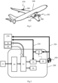
- the auxiliary power group 200 comprises in particular a set 14 of fuel cells (“Fuel Cell Stack” in English) supplied with dihydrogen and dioxygen and an environmental control system 16 (“environmental control system” or ECS in English) supplied with dioxygen.
- the auxiliary power group 200 is used to supply electrical and pneumatic energy.
- non-propulsion systems of the aircraft for example: lighting, ventilation of a passenger cabin and/or air conditioning of the cabin, etc.
- the electrical energy produced by the fuel cell assembly 14 is used in particular for lighting and cabin control even before the aircraft is started.
- Pneumatic energy is used in particular by the environmental control system 16 for ventilation, air conditioning of the cabin, temperature control and pressurization of the cabin for the crew and passengers.
- This pneumatic energy is also the main source of energy used for starting the propulsion systems 150.
- oxygen and dioxygen are used interchangeably.
- hydrogen and dihydrogen are used interchangeably.
- FIG. 2 is a schematic representation of an auxiliary power unit 200 according to a particular embodiment.
- the thick black arrows relate to a hydrogen distribution circuit and the thick white arrows relate to an air distribution circuit, in particular oxygen.
- the auxiliary power unit 200 comprises a compressor 10, for example an electric compressor, coupled to an air distributor 12 via at least one air duct.
- the air distributor also known as a manifold, is configured to distribute the air flow that it receives at the inlet to several output devices.
- the oxygen used in the auxiliary power unit 200 comes for example from the ambient air pressurized by the compressor 10, the pressurized air being used to supply an air distributor 12 (“manifold” in English).
- the ambient air comes for example from an air sampling device 8 comprising one or more scoops located near the compressor 10.
- the air distributor 12 in turn supplies air and therefore dioxygen to the fuel cell assembly 14 and the environmental control system 16.
- the air distributor 12 supplies pressurized air to a module 26 for starting the propulsion system 150.
- the environmental control system 16 is a system conventionally used in an aircraft and its internal architecture is not detailed here since it is not useful for understanding the invention.
- the environmental control system 16 comprises an external air outlet for ejecting air taken from the cabin and the cockpit.
- the fuel cell assembly 14 is further supplied with hydrogen from the tank 160 through the dihydrogen distribution circuit.
- a fuel cell is a cell in which the generation of an electrical voltage is done by the oxidation on an anode of a reducing fuel, here dihydrogen, coupled with the reduction on a cathode of an oxidant, here dioxygen from the air.
- the dioxygen is supplied by the air distributor 12, eg at a pressure of 2 bars.
- the two electrodes are in contact with a membrane, which acts as an electrolyte, thus ensuring the transport of the ions produced at the anode.
- the oxidation of dihydrogen at the anode produces H + ions and e - electrons which pass from the anode to the cathode.
- the H + ions migrate into the membrane and the electrons pass through an external circuit, thus producing electrical energy.
- the H + ions, the e - electrons, and dioxygen e.g. from the air
- 4H + + 4e - + O 2 2H 2 O.
- heat is released.
- the air not used by the fuel cells during the chemical reaction is, for example, discharged outside the aircraft.
- hydrogen is stored in liquid form in the tank 160 at a temperature of 20 kelvins and a pressure of 3 bars.
- the liquid hydrogen is vaporized using a capsule that is in contact with the tank 160.
- the capsule is a hermetic enclosure where a vacuum prevails, which makes it possible to regulate the pressure and temperature of the hydrogen in the hydrogen circuit.
- the hydrogen not used by the fuel cells during the chemical reaction is returned to the hydrogen circuit.
- the hydrogen can also be stored directly in gaseous form in the tank 160.
- the fuel cells are cooled by a cooling circuit 18. Indeed, the chemical reactions in the fuel cells produce heat that must be evacuated in order not to overheat the cells. For this purpose, the cooling circuit 18 is supplied with coolant.
- the coolant is for example a mixture of water and glycol, e.g. of the EGW type (English acronym for “Ethylene Glycol Water”).
- the outlet of the cooling circuit 18 is coupled to the inlet of a heat exchanger 20 in order to evacuate the heat.
- At least part of the heat produced is used to increase, through the heat exchanger 20, the temperature of the hydrogen leaving the tank to bring it to a value adequate, eg from 200 to 350°K, suitable for the operation of the fuel cell assembly 14. Thanks to the hydrogen passing through the heat exchanger 20, the coolant coming from the fuel cells and circulating in the heat exchanger 20 is cooled while the hydrogen heats up.
- part of the heat produced is evacuated to the outside of the installation.
- the heat exchanger 20 is also supplied with fresh air from the outside by one or more scoops at the outer skin of the aircraft.
- the scoops can be distributed around the perimeter of the outer skin and they can be, for example, of the NACA type or be of the type flush with the outer skin. Thanks to the fresh air passing through the heat exchanger 20, the coolant coming from the fuel cells and circulating in the heat exchanger 20 is cooled while the fresh air heats up.
- the heat exchanger 20 then rejects the hot air to the outside of the aircraft, for example through an ejection nozzle.
- the heat exchanger is arranged in a ram air duct of the aircraft.
- auxiliary power unit 200 The operation of the various elements of the auxiliary power unit 200 is controlled by a processing unit (not shown in the Fig.2 ). Information exchanges with this processing unit can be done using an internal network in the aircraft or a dedicated communication bus. Furthermore, the various air and hydrogen distribution circuits typically include pumps and valves (not shown in the Fig.2 ) also controlled by the processing unit.
- the propulsion system 150 also operates on hydrogen.
- the propulsion system 150 is a hydrogen combustion propulsion system.
- Hydrogen from the heat exchanger 20 is sent to the engine 150 through a pipe 155 to supply the engine with hydrogen during a start-up phase.
- the hydrogen is evaporated by heating by means of the heat exchanger 20.
- the heat generated by the fuel cell assembly 14 is advantageously used to heat the hydrogen supplying the propulsion system 150 through the heat exchanger 20.
- having the fuel cell assembly 14 co-located with the heat exchanger 20 and the propulsion system 150 allows to minimize heat losses.
- co-located is to be understood as meaning a spatial proximity of the fuel cell assembly 14 and the propulsion system 150 (respectively of the heat exchanger 20).
- a pipe 156 makes it possible to send hydrogen from the tank 160 to the engine 150 during operation of the engine, i.e. after it has started.
- the air distributor 12 is controlled by the processing unit to provide the fuel cell assembly 14 and the environmental control system 16 with a mixture of air from the compressor 10 and the propulsion system(s) 150.
- air sampling at the propulsion system(s) 150 is performed by an air sampling system 28 known by the English terminology of “bleed air system”.
- an inlet of the air distributor 12 is coupled to an outlet of the air sampling system 28.
- This embodiment makes it possible to use the energy of the propulsion system 150, and therefore to turn off the compressor 10. It also makes it possible to compensate for the failure of one or other of the sources of pressurized air.
- the processing unit obtains information relating to the air requirements of the environmental control system 16 and the battery pack 14.
- the air requirements may vary over time.
- the requirements of the environmental control system 16 may vary depending on the flight altitude, the outside temperature and the number of passengers on board the aircraft.
- the processing unit controls the distributor so that it supplies the battery pack 14 and the environmental control system depending on the information obtained relating to their respective air requirements.
- the air or a portion of the air leaving the stack that is depleted in oxygen is transmitted to the propulsion systems 150 in order to serve as a fire barrier.
- this oxygen-depleted air can advantageously be injected into compartments of the propulsion systems 150 in which a hydrogen leak is likely to occur and thus limit the risks of explosion.
- the fuel cell assembly 14 of the Figs 1 and 2 is advantageously coupled to an electrical energy storage system comprising batteries and/or capacitors.
- the auxiliary power unit 200 and the propulsion system 150 with which it is associated are co-located, i.e. are spatially close.
- the auxiliary power unit is no longer located in the tail of the aircraft, which makes it possible to avoid having to transport hydrogen in a distribution circuit along the aircraft and thus limits the risks of leakage and therefore of explosion.
- the aircraft comprises as many auxiliary power units as there are propulsion systems 150, each auxiliary power unit and the propulsion system with which it is associated being co-located.
- the auxiliary power units are connected by a crossfeed system 250 in order to compensate for a possible malfunction of at least one element of an auxiliary power unit among the compressor 10, the air distributor 12, the heat exchanger 20 or 22 and/or the air sampling system 28.
- This cross-feed system 250 is controlled by a processing unit.
- the processing unit is configured to detect a malfunction of at least one element of an auxiliary power unit and to overcome the problem according to the malfunctioning element. For example, in the event of a malfunction of the compressor and/or the distributor of the auxiliary power unit APU 1, the processing unit implements a distribution of air from the environmental control system and the fuel cell assembly of the auxiliary power unit APU 1 from the compressor and the distributor of the auxiliary power unit APU 2. In other words, the environmental control system and the fuel cell assembly of the auxiliary power unit APU 1 are supplied with air by the distributor of the auxiliary power unit APU 2.
- the processing unit controlling the cross-feed system 250 corresponds to the processing unit controlling the air distributor 12 of the first auxiliary power unit or to the processing unit controlling the air distributor 12 of the second auxiliary power unit.
- the processing unit controlling the cross-feed system 250 is independent of the processing unit controlling the air distributor 12 of the first auxiliary power unit and of the processing unit controlling the air distributor 12 of the second auxiliary power unit. However, it can exchange information with these two processing units.
- the processing unit controlling the cross-feed system 250, the processing unit controlling the air distributor 12 of the first auxiliary power unit and the processing unit controlling the air distributor 12 of the second auxiliary power unit correspond to the same processing unit.
Landscapes
- Engineering & Computer Science (AREA)
- Life Sciences & Earth Sciences (AREA)
- Sustainable Development (AREA)
- Sustainable Energy (AREA)
- Chemical & Material Sciences (AREA)
- Manufacturing & Machinery (AREA)
- General Chemical & Material Sciences (AREA)
- Electrochemistry (AREA)
- Chemical Kinetics & Catalysis (AREA)
- Aviation & Aerospace Engineering (AREA)
- Mechanical Engineering (AREA)
- Transportation (AREA)
- Power Engineering (AREA)
- Health & Medical Sciences (AREA)
- Pulmonology (AREA)
- General Health & Medical Sciences (AREA)
- Fuel Cell (AREA)
- Combustion & Propulsion (AREA)
Claims (10)
- Hilfstriebwerk für ein Flugzeug (100), beinhaltend einen Luftkompressor (10), der mit einer Vorrichtung zur Entnahme von Luft (8) auf der Außenseite des Flugzeugs gekoppelt ist, wobei der Kompressor (10) einen Luftverteiler (12) mit Druckluft versorgt, welcher dazu konfiguriert ist, eine Klimaanlage (16) und ein Startmodul (26) für mindestens ein Antriebssystem (150) des Flugzeugs, das von einem Behälter (160) aus mit Wasserstoff versorgt wird, mit Luft zu versorgen, wobei:- der Luftverteiler (12) ferner dazu konfiguriert ist, eine Anordnung von Brennstoffzellen (14) mit Luft zu versorgen, welche dazu angeordnet ist, eine Stromerzeugungsfunktion durchzuführen, die dazu bestimmt ist, Nicht-Antriebssysteme des Flugzeugs (100) zu versorgen, wobei die Anordnung von Brennstoffzellen (14) ferner von dem Behälter (160) aus mit Wasserstoff versorgt wird; wobei das Hilfstriebwerk dadurch gekennzeichnet ist, dass:- ein Eingang des Luftverteilers (12) mit einem Ausgang eines Luftentnahmesystems (28) gekoppelt ist, welches dazu konfiguriert ist, Luft im Bereich des mindestens einen Antriebssystems (150) zu entnehmen, und der Luftverteiler durch eine Verarbeitungseinheit derart gesteuert wird, dass, wenn das Antriebssystem (150) in Betrieb ist, der Luftverteiler (12) die Anordnung von Brennstoffzellen (14) und die Klimaanlage (16) mit einem Luftgemisch versorgt, das von dem Kompressor (10) und dem Antriebssystem (150) kommt.
- Hilfstriebwerk nach Anspruch 1, wobei die Verarbeitungseinheit ferner dazu konfiguriert ist, während des Betriebs des Antriebssystems (150) das Stoppen des Kompressors (10) anzusteuern.
- Hilfstriebwerk nach einem der Ansprüche 1 oder 2, wobei die Anordnung von Brennstoffzellen (14) mit einem Kühlkreislauf (18) gekoppelt ist, in dem eine Kühlflüssigkeit zirkuliert, wobei der Kühlkreislauf (18) derart konfiguriert ist, dass, wenn die Anordnung von Brennstoffzellen in Betrieb ist und dabei Wärme freisetzt, die Wärme die Kühlflüssigkeit erwärmt.
- Hilfstriebwerk nach Anspruch 3, wobei ein Ausgang des Kühlkreislaufs (18) mit einem Eingang eines Wärmetauschers (20) gekoppelt ist, durch welchen der Wasserstoff zirkuliert, der die Anordnung von Brennstoffzellen (14) versorgt, sodass mindestens ein Teil der erwärmten Kühlflüssigkeit in dem Wärmetauscher zirkuliert und den Wasserstoff erwärmt, der die Anordnung von Brennstoffzellen (14) versorgt.
- Hilfstriebwerk nach Anspruch 3 oder 4, wobei ein Teil des Wasserstoffs, der durch den Wärmetauscher zirkuliert, während einer Startphase das mindestens eine Antriebssystem versorgt.
- Hilfstriebwerk nach einem der Ansprüche 1 bis 5, wobei eine Verarbeitungseinheit des Hilfstriebwerks dazu konfiguriert ist, Informationen über den Luftbedarf der Klimaanlage und der Anordnung von Brennstoffzellen zu erhalten, und wobei die Verarbeitungseinheit den Luftverteiler derart steuert, dass dieser die Anordnung von Brennstoffzellen und die Klimaanlage in Abhängigkeit von den erhaltenen Informationen mit Luft versorgt.
- Hilfstriebwerk nach einem der Ansprüche 1 bis 6, wobei mindestens ein Teil der sauerstoffarmen Luft am Ausgang der Anordnung von Brennstoffzellen in mindestens eine Kammer des mindestens einen Antriebssystems gespritzt wird, um als Brandschutzbarriere zu dienen.
- Hilfstriebwerk nach einem der Ansprüche 1 bis 7, wobei das Hilfstriebwerk und das mindestens eine Antriebssystem kolokalisiert sind.
- Flugzeug, das mindestens ein Hilfstriebwerk nach einem der Ansprüche 1 bis 8 beinhaltet.
- Flugzeug, beinhaltend:- ein erstes Hilfstriebwerk nach einem der Ansprüche 1 bis 8 und ein zweites Hilfstriebwerk nach einem der Ansprüche 1 bis 8, wobei das erste und das zweite Hilfstriebwerk durch ein Überkreuzversorgungssystem verbunden sind; und- eine Verarbeitungseinheit, die dazu konfiguriert ist, eine Fehlfunktion mindestens eines Elements von einem von dem ersten oder dem zweiten Hilfstriebwerk zu detektieren und diese Fehlfunktion dadurch aufzufangen, dass sie das Überkreuzversorgungssystem so ansteuert, dass das entsprechende Element in dem anderen Hilfstriebwerk als Ersatz für das von der Fehlfunktion betroffene Element verwendet wird.
Applications Claiming Priority (1)
| Application Number | Priority Date | Filing Date | Title |
|---|---|---|---|
| FR2111968A FR3125799A1 (fr) | 2021-11-10 | 2021-11-10 | Groupe auxiliaire de puissance pour un aéronef |
Publications (2)
| Publication Number | Publication Date |
|---|---|
| EP4180334A1 EP4180334A1 (de) | 2023-05-17 |
| EP4180334B1 true EP4180334B1 (de) | 2024-10-09 |
Family
ID=79269774
Family Applications (1)
| Application Number | Title | Priority Date | Filing Date |
|---|---|---|---|
| EP22205880.2A Active EP4180334B1 (de) | 2021-11-10 | 2022-11-07 | Hilfstriebwerk für ein flugzeug |
Country Status (4)
| Country | Link |
|---|---|
| US (1) | US12054281B2 (de) |
| EP (1) | EP4180334B1 (de) |
| CN (1) | CN116101501A (de) |
| FR (1) | FR3125799A1 (de) |
Family Cites Families (12)
| Publication number | Priority date | Publication date | Assignee | Title |
|---|---|---|---|---|
| GB2522865B (en) * | 2014-02-06 | 2016-04-20 | Ge Aviat Systems Ltd | Fuel cell-based auxiliary power unit |
| DE102014119279A1 (de) * | 2014-12-19 | 2016-06-23 | Airbus Operations Gmbh | Hilfsenergiesystem für ein Flugzeug und ein Flugzeug mit einem derartigen Hilfsenergiesystem |
| US10160547B2 (en) * | 2015-05-26 | 2018-12-25 | Hamilton Sundstrand Corporation | Aircraft environmental control system |
| US9828870B2 (en) * | 2015-06-11 | 2017-11-28 | Northrop Grumman Systems Corporation | Efficient power and thermal management system for high performance aircraft |
| US10224556B2 (en) * | 2015-12-15 | 2019-03-05 | Hamilton Sundstrand Corporation | Integrated fuel cell aircraft pressurization and cooling system |
| US10578025B2 (en) * | 2016-05-13 | 2020-03-03 | The Boeing Company | Hybrid aircraft turbine engine starting system and method |
| FR3055886B1 (fr) * | 2016-09-15 | 2018-09-28 | Safran Power Units | Dispositif d'alimentation en energie dans un aeronef et procede de refroidissement de ce dispositif |
| US11649059B2 (en) * | 2019-05-24 | 2023-05-16 | Alakai Technologies Corporation | Integrated multimode thermal energy transfer system, method and apparatus for clean fuel electric multirotor aircraft |
| US11795872B2 (en) * | 2020-02-14 | 2023-10-24 | Rtx Corporation | Engine and secondary power unit integrated operation |
| US12110121B2 (en) * | 2020-03-05 | 2024-10-08 | Yaborã Indústria Aeronáutica S.A. | Systems and methods for defining APU steady state speed according to the aircraft operational conditions |
| US20210340908A1 (en) * | 2020-05-01 | 2021-11-04 | Raytheon Technologies Corporation | Gas turbine engines having cryogenic fuel systems |
| GB202114829D0 (en) * | 2021-10-18 | 2021-12-01 | Rolls Royce Plc | Aircraft propulsion system |
-
2021
- 2021-11-10 FR FR2111968A patent/FR3125799A1/fr not_active Ceased
-
2022
- 2022-11-07 EP EP22205880.2A patent/EP4180334B1/de active Active
- 2022-11-08 US US17/982,567 patent/US12054281B2/en active Active
- 2022-11-10 CN CN202211405912.8A patent/CN116101501A/zh active Pending
Also Published As
| Publication number | Publication date |
|---|---|
| US20230147038A1 (en) | 2023-05-11 |
| FR3125799A1 (fr) | 2023-02-03 |
| CN116101501A (zh) | 2023-05-12 |
| US12054281B2 (en) | 2024-08-06 |
| EP4180334A1 (de) | 2023-05-17 |
Similar Documents
| Publication | Publication Date | Title |
|---|---|---|
| US20230339621A1 (en) | Hydrogen fuel system for aircraft | |
| US9701416B2 (en) | Aircraft and a retrofit cryogenic fuel system | |
| US20160025339A1 (en) | Energy-efficient and controlled vaporization of cryofuels for aircraft engines | |
| US9850008B2 (en) | Integrated vehicle fluids | |
| US8657227B1 (en) | Independent power generation in aircraft | |
| US9656762B2 (en) | System for temperature and actuation control and method of controlling fluid temperatures in an aircraft | |
| US10006363B2 (en) | System and method for aviation electric power production | |
| US20130192246A1 (en) | Dual fuel aircraft engine control system and method for operating same | |
| US12313023B1 (en) | Integrated vehicle fluids with hot gas line and cold gas line merging to increase enthalpy | |
| US6296957B1 (en) | Energy supply unit on board an aircraft | |
| CA2896461A1 (en) | Cryogenic fuel system and method for delivering fuel in an aircraft | |
| CA2812250A1 (en) | Dual fuel aircraft system and method for operating same | |
| US11525402B2 (en) | Combustion chamber with solid fuel | |
| WO2024009097A1 (en) | Aircraft propulsion system and method | |
| EP4180334A1 (de) | Hilfstriebwerk für ein flugzeug | |
| EP3074308A1 (de) | Verfahren und system zur optimalen herstellung von nichtantriebsenergie | |
| TR2023003905A1 (tr) | Güneş enerji destekli sıvı hidrojen alt yapılı, hibrit enerji insanlı veya insansız araç sistemi. | |
| FR3155371A1 (fr) | Système propulsif pourvu d’une pile à combustible à haute température à intégration optimisée. |
Legal Events
| Date | Code | Title | Description |
|---|---|---|---|
| PUAI | Public reference made under article 153(3) epc to a published international application that has entered the european phase |
Free format text: ORIGINAL CODE: 0009012 |
|
| STAA | Information on the status of an ep patent application or granted ep patent |
Free format text: STATUS: THE APPLICATION HAS BEEN PUBLISHED |
|
| AK | Designated contracting states |
Kind code of ref document: A1 Designated state(s): AL AT BE BG CH CY CZ DE DK EE ES FI FR GB GR HR HU IE IS IT LI LT LU LV MC ME MK MT NL NO PL PT RO RS SE SI SK SM TR |
|
| STAA | Information on the status of an ep patent application or granted ep patent |
Free format text: STATUS: REQUEST FOR EXAMINATION WAS MADE |
|
| 17P | Request for examination filed |
Effective date: 20231113 |
|
| RBV | Designated contracting states (corrected) |
Designated state(s): AL AT BE BG CH CY CZ DE DK EE ES FI FR GB GR HR HU IE IS IT LI LT LU LV MC ME MK MT NL NO PL PT RO RS SE SI SK SM TR |
|
| GRAP | Despatch of communication of intention to grant a patent |
Free format text: ORIGINAL CODE: EPIDOSNIGR1 |
|
| STAA | Information on the status of an ep patent application or granted ep patent |
Free format text: STATUS: GRANT OF PATENT IS INTENDED |
|
| RIC1 | Information provided on ipc code assigned before grant |
Ipc: B64D 41/00 20060101AFI20231214BHEP |
|
| INTG | Intention to grant announced |
Effective date: 20240105 |
|
| GRAJ | Information related to disapproval of communication of intention to grant by the applicant or resumption of examination proceedings by the epo deleted |
Free format text: ORIGINAL CODE: EPIDOSDIGR1 |
|
| STAA | Information on the status of an ep patent application or granted ep patent |
Free format text: STATUS: REQUEST FOR EXAMINATION WAS MADE |
|
| INTC | Intention to grant announced (deleted) | ||
| GRAP | Despatch of communication of intention to grant a patent |
Free format text: ORIGINAL CODE: EPIDOSNIGR1 |
|
| STAA | Information on the status of an ep patent application or granted ep patent |
Free format text: STATUS: GRANT OF PATENT IS INTENDED |
|
| INTG | Intention to grant announced |
Effective date: 20240522 |
|
| GRAS | Grant fee paid |
Free format text: ORIGINAL CODE: EPIDOSNIGR3 |
|
| GRAA | (expected) grant |
Free format text: ORIGINAL CODE: 0009210 |
|
| STAA | Information on the status of an ep patent application or granted ep patent |
Free format text: STATUS: THE PATENT HAS BEEN GRANTED |
|
| AK | Designated contracting states |
Kind code of ref document: B1 Designated state(s): AL AT BE BG CH CY CZ DE DK EE ES FI FR GB GR HR HU IE IS IT LI LT LU LV MC ME MK MT NL NO PL PT RO RS SE SI SK SM TR |
|
| REG | Reference to a national code |
Ref country code: CH Ref legal event code: EP |
|
| REG | Reference to a national code |
Ref country code: DE Ref legal event code: R096 Ref document number: 602022006669 Country of ref document: DE |
|
| REG | Reference to a national code |
Ref country code: IE Ref legal event code: FG4D Free format text: LANGUAGE OF EP DOCUMENT: FRENCH |
|
| REG | Reference to a national code |
Ref country code: LT Ref legal event code: MG9D |
|
| REG | Reference to a national code |
Ref country code: NL Ref legal event code: MP Effective date: 20241009 |
|
| REG | Reference to a national code |
Ref country code: AT Ref legal event code: MK05 Ref document number: 1730360 Country of ref document: AT Kind code of ref document: T Effective date: 20241009 |
|
| PG25 | Lapsed in a contracting state [announced via postgrant information from national office to epo] |
Ref country code: NL Free format text: LAPSE BECAUSE OF FAILURE TO SUBMIT A TRANSLATION OF THE DESCRIPTION OR TO PAY THE FEE WITHIN THE PRESCRIBED TIME-LIMIT Effective date: 20241009 |
|
| PG25 | Lapsed in a contracting state [announced via postgrant information from national office to epo] |
Ref country code: NL Free format text: LAPSE BECAUSE OF FAILURE TO SUBMIT A TRANSLATION OF THE DESCRIPTION OR TO PAY THE FEE WITHIN THE PRESCRIBED TIME-LIMIT Effective date: 20241009 |
|
| PG25 | Lapsed in a contracting state [announced via postgrant information from national office to epo] |
Ref country code: HR Free format text: LAPSE BECAUSE OF FAILURE TO SUBMIT A TRANSLATION OF THE DESCRIPTION OR TO PAY THE FEE WITHIN THE PRESCRIBED TIME-LIMIT Effective date: 20241009 Ref country code: IS Free format text: LAPSE BECAUSE OF FAILURE TO SUBMIT A TRANSLATION OF THE DESCRIPTION OR TO PAY THE FEE WITHIN THE PRESCRIBED TIME-LIMIT Effective date: 20250209 Ref country code: PT Free format text: LAPSE BECAUSE OF FAILURE TO SUBMIT A TRANSLATION OF THE DESCRIPTION OR TO PAY THE FEE WITHIN THE PRESCRIBED TIME-LIMIT Effective date: 20250210 |
|
| PG25 | Lapsed in a contracting state [announced via postgrant information from national office to epo] |
Ref country code: FI Free format text: LAPSE BECAUSE OF FAILURE TO SUBMIT A TRANSLATION OF THE DESCRIPTION OR TO PAY THE FEE WITHIN THE PRESCRIBED TIME-LIMIT Effective date: 20241009 |
|
| PG25 | Lapsed in a contracting state [announced via postgrant information from national office to epo] |
Ref country code: BG Free format text: LAPSE BECAUSE OF FAILURE TO SUBMIT A TRANSLATION OF THE DESCRIPTION OR TO PAY THE FEE WITHIN THE PRESCRIBED TIME-LIMIT Effective date: 20241009 |
|
| PG25 | Lapsed in a contracting state [announced via postgrant information from national office to epo] |
Ref country code: ES Free format text: LAPSE BECAUSE OF FAILURE TO SUBMIT A TRANSLATION OF THE DESCRIPTION OR TO PAY THE FEE WITHIN THE PRESCRIBED TIME-LIMIT Effective date: 20241009 |
|
| PG25 | Lapsed in a contracting state [announced via postgrant information from national office to epo] |
Ref country code: NO Free format text: LAPSE BECAUSE OF FAILURE TO SUBMIT A TRANSLATION OF THE DESCRIPTION OR TO PAY THE FEE WITHIN THE PRESCRIBED TIME-LIMIT Effective date: 20250109 |
|
| PG25 | Lapsed in a contracting state [announced via postgrant information from national office to epo] |
Ref country code: AT Free format text: LAPSE BECAUSE OF FAILURE TO SUBMIT A TRANSLATION OF THE DESCRIPTION OR TO PAY THE FEE WITHIN THE PRESCRIBED TIME-LIMIT Effective date: 20241009 Ref country code: GR Free format text: LAPSE BECAUSE OF FAILURE TO SUBMIT A TRANSLATION OF THE DESCRIPTION OR TO PAY THE FEE WITHIN THE PRESCRIBED TIME-LIMIT Effective date: 20250110 Ref country code: LV Free format text: LAPSE BECAUSE OF FAILURE TO SUBMIT A TRANSLATION OF THE DESCRIPTION OR TO PAY THE FEE WITHIN THE PRESCRIBED TIME-LIMIT Effective date: 20241009 |
|
| PG25 | Lapsed in a contracting state [announced via postgrant information from national office to epo] |
Ref country code: PL Free format text: LAPSE BECAUSE OF FAILURE TO SUBMIT A TRANSLATION OF THE DESCRIPTION OR TO PAY THE FEE WITHIN THE PRESCRIBED TIME-LIMIT Effective date: 20241009 |
|
| PG25 | Lapsed in a contracting state [announced via postgrant information from national office to epo] |
Ref country code: RS Free format text: LAPSE BECAUSE OF FAILURE TO SUBMIT A TRANSLATION OF THE DESCRIPTION OR TO PAY THE FEE WITHIN THE PRESCRIBED TIME-LIMIT Effective date: 20250109 |
|
| PG25 | Lapsed in a contracting state [announced via postgrant information from national office to epo] |
Ref country code: SM Free format text: LAPSE BECAUSE OF FAILURE TO SUBMIT A TRANSLATION OF THE DESCRIPTION OR TO PAY THE FEE WITHIN THE PRESCRIBED TIME-LIMIT Effective date: 20241009 |
|
| PG25 | Lapsed in a contracting state [announced via postgrant information from national office to epo] |
Ref country code: MC Free format text: LAPSE BECAUSE OF FAILURE TO SUBMIT A TRANSLATION OF THE DESCRIPTION OR TO PAY THE FEE WITHIN THE PRESCRIBED TIME-LIMIT Effective date: 20241009 |
|
| PG25 | Lapsed in a contracting state [announced via postgrant information from national office to epo] |
Ref country code: DK Free format text: LAPSE BECAUSE OF FAILURE TO SUBMIT A TRANSLATION OF THE DESCRIPTION OR TO PAY THE FEE WITHIN THE PRESCRIBED TIME-LIMIT Effective date: 20241009 |
|
| REG | Reference to a national code |
Ref country code: DE Ref legal event code: R097 Ref document number: 602022006669 Country of ref document: DE |
|
| PG25 | Lapsed in a contracting state [announced via postgrant information from national office to epo] |
Ref country code: LU Free format text: LAPSE BECAUSE OF NON-PAYMENT OF DUE FEES Effective date: 20241107 |
|
| PG25 | Lapsed in a contracting state [announced via postgrant information from national office to epo] |
Ref country code: EE Free format text: LAPSE BECAUSE OF FAILURE TO SUBMIT A TRANSLATION OF THE DESCRIPTION OR TO PAY THE FEE WITHIN THE PRESCRIBED TIME-LIMIT Effective date: 20241009 |
|
| PG25 | Lapsed in a contracting state [announced via postgrant information from national office to epo] |
Ref country code: RO Free format text: LAPSE BECAUSE OF FAILURE TO SUBMIT A TRANSLATION OF THE DESCRIPTION OR TO PAY THE FEE WITHIN THE PRESCRIBED TIME-LIMIT Effective date: 20241009 |
|
| PG25 | Lapsed in a contracting state [announced via postgrant information from national office to epo] |
Ref country code: SK Free format text: LAPSE BECAUSE OF FAILURE TO SUBMIT A TRANSLATION OF THE DESCRIPTION OR TO PAY THE FEE WITHIN THE PRESCRIBED TIME-LIMIT Effective date: 20241009 |
|
| PG25 | Lapsed in a contracting state [announced via postgrant information from national office to epo] |
Ref country code: CZ Free format text: LAPSE BECAUSE OF FAILURE TO SUBMIT A TRANSLATION OF THE DESCRIPTION OR TO PAY THE FEE WITHIN THE PRESCRIBED TIME-LIMIT Effective date: 20241009 |
|
| PG25 | Lapsed in a contracting state [announced via postgrant information from national office to epo] |
Ref country code: IT Free format text: LAPSE BECAUSE OF FAILURE TO SUBMIT A TRANSLATION OF THE DESCRIPTION OR TO PAY THE FEE WITHIN THE PRESCRIBED TIME-LIMIT Effective date: 20241009 |
|
| PLBE | No opposition filed within time limit |
Free format text: ORIGINAL CODE: 0009261 |
|
| STAA | Information on the status of an ep patent application or granted ep patent |
Free format text: STATUS: NO OPPOSITION FILED WITHIN TIME LIMIT |
|
| REG | Reference to a national code |
Ref country code: BE Ref legal event code: MM Effective date: 20241130 |
|
| PG25 | Lapsed in a contracting state [announced via postgrant information from national office to epo] |
Ref country code: SE Free format text: LAPSE BECAUSE OF FAILURE TO SUBMIT A TRANSLATION OF THE DESCRIPTION OR TO PAY THE FEE WITHIN THE PRESCRIBED TIME-LIMIT Effective date: 20241009 |
|
| 26N | No opposition filed |
Effective date: 20250710 |
|
| PG25 | Lapsed in a contracting state [announced via postgrant information from national office to epo] |
Ref country code: BE Free format text: LAPSE BECAUSE OF NON-PAYMENT OF DUE FEES Effective date: 20241130 |
|
| PG25 | Lapsed in a contracting state [announced via postgrant information from national office to epo] |
Ref country code: IE Free format text: LAPSE BECAUSE OF NON-PAYMENT OF DUE FEES Effective date: 20241107 |
|
| PGFP | Annual fee paid to national office [announced via postgrant information from national office to epo] |
Ref country code: DE Payment date: 20251119 Year of fee payment: 4 |
|
| PGFP | Annual fee paid to national office [announced via postgrant information from national office to epo] |
Ref country code: FR Payment date: 20251126 Year of fee payment: 4 |
|
| PG25 | Lapsed in a contracting state [announced via postgrant information from national office to epo] |
Ref country code: HU Free format text: LAPSE BECAUSE OF FAILURE TO SUBMIT A TRANSLATION OF THE DESCRIPTION OR TO PAY THE FEE WITHIN THE PRESCRIBED TIME-LIMIT; INVALID AB INITIO Effective date: 20221107 |
|
| PG25 | Lapsed in a contracting state [announced via postgrant information from national office to epo] |
Ref country code: CY Free format text: LAPSE BECAUSE OF FAILURE TO SUBMIT A TRANSLATION OF THE DESCRIPTION OR TO PAY THE FEE WITHIN THE PRESCRIBED TIME-LIMIT; INVALID AB INITIO Effective date: 20221107 |