EP4180334B1 - Groupe auxiliaire de puissance pour un aéronef - Google Patents
Groupe auxiliaire de puissance pour un aéronef Download PDFInfo
- Publication number
- EP4180334B1 EP4180334B1 EP22205880.2A EP22205880A EP4180334B1 EP 4180334 B1 EP4180334 B1 EP 4180334B1 EP 22205880 A EP22205880 A EP 22205880A EP 4180334 B1 EP4180334 B1 EP 4180334B1
- Authority
- EP
- European Patent Office
- Prior art keywords
- auxiliary power
- power unit
- air
- aircraft
- fuel cell
- Prior art date
- Legal status (The legal status is an assumption and is not a legal conclusion. Google has not performed a legal analysis and makes no representation as to the accuracy of the status listed.)
- Active
Links
Images

Classifications
-
- B—PERFORMING OPERATIONS; TRANSPORTING
- B64—AIRCRAFT; AVIATION; COSMONAUTICS
- B64D—EQUIPMENT FOR FITTING IN OR TO AIRCRAFT; FLIGHT SUITS; PARACHUTES; ARRANGEMENT OR MOUNTING OF POWER PLANTS OR PROPULSION TRANSMISSIONS IN AIRCRAFT
- B64D41/00—Power installations for auxiliary purposes
-
- B—PERFORMING OPERATIONS; TRANSPORTING
- B60—VEHICLES IN GENERAL
- B60L—PROPULSION OF ELECTRICALLY-PROPELLED VEHICLES; SUPPLYING ELECTRIC POWER FOR AUXILIARY EQUIPMENT OF ELECTRICALLY-PROPELLED VEHICLES; ELECTRODYNAMIC BRAKE SYSTEMS FOR VEHICLES IN GENERAL; MAGNETIC SUSPENSION OR LEVITATION FOR VEHICLES; MONITORING OPERATING VARIABLES OF ELECTRICALLY-PROPELLED VEHICLES; ELECTRIC SAFETY DEVICES FOR ELECTRICALLY-PROPELLED VEHICLES
- B60L58/00—Methods or circuit arrangements for monitoring or controlling batteries or fuel cells, specially adapted for electric vehicles
- B60L58/30—Methods or circuit arrangements for monitoring or controlling batteries or fuel cells, specially adapted for electric vehicles for monitoring or controlling fuel cells
- B60L58/32—Methods or circuit arrangements for monitoring or controlling batteries or fuel cells, specially adapted for electric vehicles for monitoring or controlling fuel cells for controlling the temperature of fuel cells, e.g. by controlling the electric load
- B60L58/33—Methods or circuit arrangements for monitoring or controlling batteries or fuel cells, specially adapted for electric vehicles for monitoring or controlling fuel cells for controlling the temperature of fuel cells, e.g. by controlling the electric load by cooling
-
- B—PERFORMING OPERATIONS; TRANSPORTING
- B64—AIRCRAFT; AVIATION; COSMONAUTICS
- B64D—EQUIPMENT FOR FITTING IN OR TO AIRCRAFT; FLIGHT SUITS; PARACHUTES; ARRANGEMENT OR MOUNTING OF POWER PLANTS OR PROPULSION TRANSMISSIONS IN AIRCRAFT
- B64D13/00—Arrangements or adaptations of air-treatment apparatus for aircraft crew or passengers, or freight space
- B64D13/06—Arrangements or adaptations of air-treatment apparatus for aircraft crew or passengers, or freight space the air being conditioned
-
- H—ELECTRICITY
- H01—ELECTRIC ELEMENTS
- H01M—PROCESSES OR MEANS, e.g. BATTERIES, FOR THE DIRECT CONVERSION OF CHEMICAL ENERGY INTO ELECTRICAL ENERGY
- H01M8/00—Fuel cells; Manufacture thereof
- H01M8/04—Auxiliary arrangements, e.g. for control of pressure or for circulation of fluids
- H01M8/04007—Auxiliary arrangements, e.g. for control of pressure or for circulation of fluids related to heat exchange
- H01M8/04029—Heat exchange using liquids
-
- H—ELECTRICITY
- H01—ELECTRIC ELEMENTS
- H01M—PROCESSES OR MEANS, e.g. BATTERIES, FOR THE DIRECT CONVERSION OF CHEMICAL ENERGY INTO ELECTRICAL ENERGY
- H01M8/00—Fuel cells; Manufacture thereof
- H01M8/04—Auxiliary arrangements, e.g. for control of pressure or for circulation of fluids
- H01M8/04007—Auxiliary arrangements, e.g. for control of pressure or for circulation of fluids related to heat exchange
- H01M8/04067—Heat exchange or temperature measuring elements, thermal insulation, e.g. heat pipes, heat pumps, fins
- H01M8/04074—Heat exchange unit structures specially adapted for fuel cell
-
- H—ELECTRICITY
- H01—ELECTRIC ELEMENTS
- H01M—PROCESSES OR MEANS, e.g. BATTERIES, FOR THE DIRECT CONVERSION OF CHEMICAL ENERGY INTO ELECTRICAL ENERGY
- H01M8/00—Fuel cells; Manufacture thereof
- H01M8/04—Auxiliary arrangements, e.g. for control of pressure or for circulation of fluids
- H01M8/04082—Arrangements for control of reactant parameters, e.g. pressure or concentration
- H01M8/04089—Arrangements for control of reactant parameters, e.g. pressure or concentration of gaseous reactants
- H01M8/04111—Arrangements for control of reactant parameters, e.g. pressure or concentration of gaseous reactants using a compressor turbine assembly
-
- H—ELECTRICITY
- H01—ELECTRIC ELEMENTS
- H01M—PROCESSES OR MEANS, e.g. BATTERIES, FOR THE DIRECT CONVERSION OF CHEMICAL ENERGY INTO ELECTRICAL ENERGY
- H01M8/00—Fuel cells; Manufacture thereof
- H01M8/04—Auxiliary arrangements, e.g. for control of pressure or for circulation of fluids
- H01M8/04298—Processes for controlling fuel cells or fuel cell systems
- H01M8/04313—Processes for controlling fuel cells or fuel cell systems characterised by the detection or assessment of variables; characterised by the detection or assessment of failure or abnormal function
- H01M8/04664—Failure or abnormal function
-
- H—ELECTRICITY
- H01—ELECTRIC ELEMENTS
- H01M—PROCESSES OR MEANS, e.g. BATTERIES, FOR THE DIRECT CONVERSION OF CHEMICAL ENERGY INTO ELECTRICAL ENERGY
- H01M8/00—Fuel cells; Manufacture thereof
- H01M8/04—Auxiliary arrangements, e.g. for control of pressure or for circulation of fluids
- H01M8/04298—Processes for controlling fuel cells or fuel cell systems
- H01M8/04694—Processes for controlling fuel cells or fuel cell systems characterised by variables to be controlled
- H01M8/04746—Pressure; Flow
- H01M8/04753—Pressure; Flow of fuel cell reactants
-
- H—ELECTRICITY
- H01—ELECTRIC ELEMENTS
- H01M—PROCESSES OR MEANS, e.g. BATTERIES, FOR THE DIRECT CONVERSION OF CHEMICAL ENERGY INTO ELECTRICAL ENERGY
- H01M8/00—Fuel cells; Manufacture thereof
- H01M8/04—Auxiliary arrangements, e.g. for control of pressure or for circulation of fluids
- H01M8/04298—Processes for controlling fuel cells or fuel cell systems
- H01M8/04694—Processes for controlling fuel cells or fuel cell systems characterised by variables to be controlled
- H01M8/04746—Pressure; Flow
- H01M8/04776—Pressure; Flow at auxiliary devices, e.g. reformer, compressor, burner
-
- B—PERFORMING OPERATIONS; TRANSPORTING
- B60—VEHICLES IN GENERAL
- B60L—PROPULSION OF ELECTRICALLY-PROPELLED VEHICLES; SUPPLYING ELECTRIC POWER FOR AUXILIARY EQUIPMENT OF ELECTRICALLY-PROPELLED VEHICLES; ELECTRODYNAMIC BRAKE SYSTEMS FOR VEHICLES IN GENERAL; MAGNETIC SUSPENSION OR LEVITATION FOR VEHICLES; MONITORING OPERATING VARIABLES OF ELECTRICALLY-PROPELLED VEHICLES; ELECTRIC SAFETY DEVICES FOR ELECTRICALLY-PROPELLED VEHICLES
- B60L2200/00—Type of vehicles
- B60L2200/10—Air crafts
-
- B—PERFORMING OPERATIONS; TRANSPORTING
- B64—AIRCRAFT; AVIATION; COSMONAUTICS
- B64D—EQUIPMENT FOR FITTING IN OR TO AIRCRAFT; FLIGHT SUITS; PARACHUTES; ARRANGEMENT OR MOUNTING OF POWER PLANTS OR PROPULSION TRANSMISSIONS IN AIRCRAFT
- B64D13/00—Arrangements or adaptations of air-treatment apparatus for aircraft crew or passengers, or freight space
- B64D13/06—Arrangements or adaptations of air-treatment apparatus for aircraft crew or passengers, or freight space the air being conditioned
- B64D2013/0603—Environmental Control Systems
- B64D2013/0611—Environmental Control Systems combined with auxiliary power units (APU's)
-
- B—PERFORMING OPERATIONS; TRANSPORTING
- B64—AIRCRAFT; AVIATION; COSMONAUTICS
- B64D—EQUIPMENT FOR FITTING IN OR TO AIRCRAFT; FLIGHT SUITS; PARACHUTES; ARRANGEMENT OR MOUNTING OF POWER PLANTS OR PROPULSION TRANSMISSIONS IN AIRCRAFT
- B64D41/00—Power installations for auxiliary purposes
- B64D2041/005—Fuel cells
-
- H—ELECTRICITY
- H01—ELECTRIC ELEMENTS
- H01M—PROCESSES OR MEANS, e.g. BATTERIES, FOR THE DIRECT CONVERSION OF CHEMICAL ENERGY INTO ELECTRICAL ENERGY
- H01M2250/00—Fuel cells for particular applications; Specific features of fuel cell system
- H01M2250/20—Fuel cells in motive systems, e.g. vehicle, ship, plane
-
- Y—GENERAL TAGGING OF NEW TECHNOLOGICAL DEVELOPMENTS; GENERAL TAGGING OF CROSS-SECTIONAL TECHNOLOGIES SPANNING OVER SEVERAL SECTIONS OF THE IPC; TECHNICAL SUBJECTS COVERED BY FORMER USPC CROSS-REFERENCE ART COLLECTIONS [XRACs] AND DIGESTS
- Y02—TECHNOLOGIES OR APPLICATIONS FOR MITIGATION OR ADAPTATION AGAINST CLIMATE CHANGE
- Y02T—CLIMATE CHANGE MITIGATION TECHNOLOGIES RELATED TO TRANSPORTATION
- Y02T90/00—Enabling technologies or technologies with a potential or indirect contribution to GHG emissions mitigation
- Y02T90/40—Application of hydrogen technology to transportation, e.g. using fuel cells
Definitions
- At least one embodiment relates to an auxiliary power unit for an aircraft comprising an air compressor coupled to an air sampling device outside the aircraft. At least one other embodiment relates to an aircraft comprising such an auxiliary power unit.
- an auxiliary power unit or APU refers to an auxiliary unit that provides energy for functions other than propulsion.
- APU is intended to produce electrical energy and pneumatic energy (energy stored in a compressed gas) on board aircraft to power the various on-board systems on the ground (e.g. cabin lighting system, air conditioning, ventilation, etc.) when the main propulsion systems are stopped in order to save fuel.
- the pneumatic energy thus produced is also used to start the aircraft's propulsion systems.
- Such an auxiliary power unit can also be used in flight.
- Auxiliary power units are typically positioned at the rear of the aircraft in the tail cone to reduce their noise impact on passengers. They are fueled with kerosene from the aircraft's fuel tanks. As such, auxiliary power units consume some of the aircraft's kerosene and contribute to aviation's greenhouse gas emissions.
- a new generation of aircraft running on dihydrogen is being developed. These new aircraft are less polluting because they mainly emit water vapor. Therefore, supplying an auxiliary power unit in such aircraft with kerosene would be inconsistent for environmental reasons. Supplying the auxiliary power unit with dihydrogen would require the installation of a dihydrogen supply circuit between the tail of the aircraft and the dihydrogen tank generally located near the wings of the aircraft. Such an architecture would pose safety problems related to the risks of dihydrogen leakage and explosion along the dihydrogen supply circuit.
- auxiliary power unit comprising an electric motor powered by a set of fuel cells and driving a compressor, an output of which can be coupled to an aircraft air conditioning system via a valve.
- the fuel cells are traversed by an air flow upstream of an inlet of the compressor.
- At least one embodiment relates to an auxiliary power unit for an aircraft comprising an air compressor coupled to a device for sampling air outside the aircraft.
- the compressor supplies compressed air to an air distributor configured to supply air to an environmental control system and a start-up module of at least one propulsion system of the aircraft supplied with hydrogen from a tank.
- the air distributor is further configured to supply air to a set of fuel cells arranged to perform an electrical generation function intended to supply non-propulsion systems of the aircraft, said set of fuel cells being further supplied with hydrogen from said tank.
- an inlet of said air distributor is coupled to an outlet of an air sampling system configured to sample air from said at least one propulsion system and the air distributor is controlled by a processing unit such that, when said propulsion system is operating, the air distributor supplies the fuel cell stack and the environmental control system with a mixture of air from the compressor and the propulsion system.
- the processing unit is further configured to control the stopping of the compressor during operation of the propulsion system, in particular during flight phases of the aircraft during which the flow of air taken at said at least one propulsion system is sufficient to supply pressurized air to the fuel cell assembly and the environmental control system.
- the fuel cell assembly is coupled to a cooling circuit in which a coolant circulates, said cooling circuit being configured such that, when the fuel cell assembly operates by releasing heat, said heat warms said coolant.
- an outlet of said cooling circuit is coupled to an inlet of a heat exchanger through which the hydrogen supplying said set of fuel cells circulates so that at least a portion of said heated coolant circulates in said heat exchanger and heats the hydrogen supplying said set of fuel cells.
- a portion of the hydrogen circulating through the heat exchanger supplies said at least one propulsion system during a start-up phase.
- a processing unit of said auxiliary power unit is configured to obtain information relating to the air requirements of the environmental control system and the fuel cell assembly.
- the processing unit also controls the air distributor so that it supplies air to the fuel cell assembly and the environmental control system according to said obtained information.
- At least part of the air leaving the fuel cell assembly is injected into at least one compartment of said at least one propulsion system.
- the auxiliary power group and said at least one propulsion system are co-located.
- An aircraft comprising a first auxiliary power unit according to any of the preceding embodiments and a second auxiliary power unit according to any of the preceding embodiments is described.
- the first and second auxiliary power units are connected by a cross-power system.
- the auxiliary power group 200 comprises in particular a set 14 of fuel cells (“Fuel Cell Stack” in English) supplied with dihydrogen and dioxygen and an environmental control system 16 (“environmental control system” or ECS in English) supplied with dioxygen.
- the auxiliary power group 200 is used to supply electrical and pneumatic energy.
- non-propulsion systems of the aircraft for example: lighting, ventilation of a passenger cabin and/or air conditioning of the cabin, etc.
- the electrical energy produced by the fuel cell assembly 14 is used in particular for lighting and cabin control even before the aircraft is started.
- Pneumatic energy is used in particular by the environmental control system 16 for ventilation, air conditioning of the cabin, temperature control and pressurization of the cabin for the crew and passengers.
- This pneumatic energy is also the main source of energy used for starting the propulsion systems 150.
- oxygen and dioxygen are used interchangeably.
- hydrogen and dihydrogen are used interchangeably.
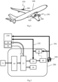
- FIG. 2 is a schematic representation of an auxiliary power unit 200 according to a particular embodiment.
- the thick black arrows relate to a hydrogen distribution circuit and the thick white arrows relate to an air distribution circuit, in particular oxygen.
- the auxiliary power unit 200 comprises a compressor 10, for example an electric compressor, coupled to an air distributor 12 via at least one air duct.
- the air distributor also known as a manifold, is configured to distribute the air flow that it receives at the inlet to several output devices.
- the oxygen used in the auxiliary power unit 200 comes for example from the ambient air pressurized by the compressor 10, the pressurized air being used to supply an air distributor 12 (“manifold” in English).
- the ambient air comes for example from an air sampling device 8 comprising one or more scoops located near the compressor 10.
- the air distributor 12 in turn supplies air and therefore dioxygen to the fuel cell assembly 14 and the environmental control system 16.
- the air distributor 12 supplies pressurized air to a module 26 for starting the propulsion system 150.
- the environmental control system 16 is a system conventionally used in an aircraft and its internal architecture is not detailed here since it is not useful for understanding the invention.
- the environmental control system 16 comprises an external air outlet for ejecting air taken from the cabin and the cockpit.
- the fuel cell assembly 14 is further supplied with hydrogen from the tank 160 through the dihydrogen distribution circuit.
- a fuel cell is a cell in which the generation of an electrical voltage is done by the oxidation on an anode of a reducing fuel, here dihydrogen, coupled with the reduction on a cathode of an oxidant, here dioxygen from the air.
- the dioxygen is supplied by the air distributor 12, eg at a pressure of 2 bars.
- the two electrodes are in contact with a membrane, which acts as an electrolyte, thus ensuring the transport of the ions produced at the anode.
- the oxidation of dihydrogen at the anode produces H + ions and e - electrons which pass from the anode to the cathode.
- the H + ions migrate into the membrane and the electrons pass through an external circuit, thus producing electrical energy.
- the H + ions, the e - electrons, and dioxygen e.g. from the air
- 4H + + 4e - + O 2 2H 2 O.
- heat is released.
- the air not used by the fuel cells during the chemical reaction is, for example, discharged outside the aircraft.
- hydrogen is stored in liquid form in the tank 160 at a temperature of 20 kelvins and a pressure of 3 bars.
- the liquid hydrogen is vaporized using a capsule that is in contact with the tank 160.
- the capsule is a hermetic enclosure where a vacuum prevails, which makes it possible to regulate the pressure and temperature of the hydrogen in the hydrogen circuit.
- the hydrogen not used by the fuel cells during the chemical reaction is returned to the hydrogen circuit.
- the hydrogen can also be stored directly in gaseous form in the tank 160.
- the fuel cells are cooled by a cooling circuit 18. Indeed, the chemical reactions in the fuel cells produce heat that must be evacuated in order not to overheat the cells. For this purpose, the cooling circuit 18 is supplied with coolant.
- the coolant is for example a mixture of water and glycol, e.g. of the EGW type (English acronym for “Ethylene Glycol Water”).
- the outlet of the cooling circuit 18 is coupled to the inlet of a heat exchanger 20 in order to evacuate the heat.
- At least part of the heat produced is used to increase, through the heat exchanger 20, the temperature of the hydrogen leaving the tank to bring it to a value adequate, eg from 200 to 350°K, suitable for the operation of the fuel cell assembly 14. Thanks to the hydrogen passing through the heat exchanger 20, the coolant coming from the fuel cells and circulating in the heat exchanger 20 is cooled while the hydrogen heats up.
- part of the heat produced is evacuated to the outside of the installation.
- the heat exchanger 20 is also supplied with fresh air from the outside by one or more scoops at the outer skin of the aircraft.
- the scoops can be distributed around the perimeter of the outer skin and they can be, for example, of the NACA type or be of the type flush with the outer skin. Thanks to the fresh air passing through the heat exchanger 20, the coolant coming from the fuel cells and circulating in the heat exchanger 20 is cooled while the fresh air heats up.
- the heat exchanger 20 then rejects the hot air to the outside of the aircraft, for example through an ejection nozzle.
- the heat exchanger is arranged in a ram air duct of the aircraft.
- auxiliary power unit 200 The operation of the various elements of the auxiliary power unit 200 is controlled by a processing unit (not shown in the Fig.2 ). Information exchanges with this processing unit can be done using an internal network in the aircraft or a dedicated communication bus. Furthermore, the various air and hydrogen distribution circuits typically include pumps and valves (not shown in the Fig.2 ) also controlled by the processing unit.
- the propulsion system 150 also operates on hydrogen.
- the propulsion system 150 is a hydrogen combustion propulsion system.
- Hydrogen from the heat exchanger 20 is sent to the engine 150 through a pipe 155 to supply the engine with hydrogen during a start-up phase.
- the hydrogen is evaporated by heating by means of the heat exchanger 20.
- the heat generated by the fuel cell assembly 14 is advantageously used to heat the hydrogen supplying the propulsion system 150 through the heat exchanger 20.
- having the fuel cell assembly 14 co-located with the heat exchanger 20 and the propulsion system 150 allows to minimize heat losses.
- co-located is to be understood as meaning a spatial proximity of the fuel cell assembly 14 and the propulsion system 150 (respectively of the heat exchanger 20).
- a pipe 156 makes it possible to send hydrogen from the tank 160 to the engine 150 during operation of the engine, i.e. after it has started.
- the air distributor 12 is controlled by the processing unit to provide the fuel cell assembly 14 and the environmental control system 16 with a mixture of air from the compressor 10 and the propulsion system(s) 150.
- air sampling at the propulsion system(s) 150 is performed by an air sampling system 28 known by the English terminology of “bleed air system”.
- an inlet of the air distributor 12 is coupled to an outlet of the air sampling system 28.
- This embodiment makes it possible to use the energy of the propulsion system 150, and therefore to turn off the compressor 10. It also makes it possible to compensate for the failure of one or other of the sources of pressurized air.
- the processing unit obtains information relating to the air requirements of the environmental control system 16 and the battery pack 14.
- the air requirements may vary over time.
- the requirements of the environmental control system 16 may vary depending on the flight altitude, the outside temperature and the number of passengers on board the aircraft.
- the processing unit controls the distributor so that it supplies the battery pack 14 and the environmental control system depending on the information obtained relating to their respective air requirements.
- the air or a portion of the air leaving the stack that is depleted in oxygen is transmitted to the propulsion systems 150 in order to serve as a fire barrier.
- this oxygen-depleted air can advantageously be injected into compartments of the propulsion systems 150 in which a hydrogen leak is likely to occur and thus limit the risks of explosion.
- the fuel cell assembly 14 of the Figs 1 and 2 is advantageously coupled to an electrical energy storage system comprising batteries and/or capacitors.
- the auxiliary power unit 200 and the propulsion system 150 with which it is associated are co-located, i.e. are spatially close.
- the auxiliary power unit is no longer located in the tail of the aircraft, which makes it possible to avoid having to transport hydrogen in a distribution circuit along the aircraft and thus limits the risks of leakage and therefore of explosion.
- the aircraft comprises as many auxiliary power units as there are propulsion systems 150, each auxiliary power unit and the propulsion system with which it is associated being co-located.
- the auxiliary power units are connected by a crossfeed system 250 in order to compensate for a possible malfunction of at least one element of an auxiliary power unit among the compressor 10, the air distributor 12, the heat exchanger 20 or 22 and/or the air sampling system 28.
- This cross-feed system 250 is controlled by a processing unit.
- the processing unit is configured to detect a malfunction of at least one element of an auxiliary power unit and to overcome the problem according to the malfunctioning element. For example, in the event of a malfunction of the compressor and/or the distributor of the auxiliary power unit APU 1, the processing unit implements a distribution of air from the environmental control system and the fuel cell assembly of the auxiliary power unit APU 1 from the compressor and the distributor of the auxiliary power unit APU 2. In other words, the environmental control system and the fuel cell assembly of the auxiliary power unit APU 1 are supplied with air by the distributor of the auxiliary power unit APU 2.
- the processing unit controlling the cross-feed system 250 corresponds to the processing unit controlling the air distributor 12 of the first auxiliary power unit or to the processing unit controlling the air distributor 12 of the second auxiliary power unit.
- the processing unit controlling the cross-feed system 250 is independent of the processing unit controlling the air distributor 12 of the first auxiliary power unit and of the processing unit controlling the air distributor 12 of the second auxiliary power unit. However, it can exchange information with these two processing units.
- the processing unit controlling the cross-feed system 250, the processing unit controlling the air distributor 12 of the first auxiliary power unit and the processing unit controlling the air distributor 12 of the second auxiliary power unit correspond to the same processing unit.
Landscapes
- Engineering & Computer Science (AREA)
- Life Sciences & Earth Sciences (AREA)
- Sustainable Development (AREA)
- Sustainable Energy (AREA)
- Chemical & Material Sciences (AREA)
- Manufacturing & Machinery (AREA)
- General Chemical & Material Sciences (AREA)
- Electrochemistry (AREA)
- Chemical Kinetics & Catalysis (AREA)
- Aviation & Aerospace Engineering (AREA)
- Mechanical Engineering (AREA)
- Transportation (AREA)
- Power Engineering (AREA)
- Health & Medical Sciences (AREA)
- Pulmonology (AREA)
- General Health & Medical Sciences (AREA)
- Fuel Cell (AREA)
- Combustion & Propulsion (AREA)
Description
- Au moins un mode de réalisation concerne un groupe auxiliaire de puissance pour un aéronef comprenant un compresseur d'air couplé à un dispositif de prélèvement d'air à l'extérieur de l'aéronef. Au moins un autre mode de réalisation concerne un aéronef comprenant un tel groupe auxiliaire de puissance.
- Dans le domaine de l'aéronautique, un groupe auxiliaire de puissance ou APU (acronyme anglais de « auxiliary power unit ») désigne un groupe auxiliaire qui fournit de l'énergie pour des fonctions autres que la propulsion. Notamment, il est destiné à produire une énergie électrique et une énergie pneumatique (énergie emmagasinée dans un gaz comprimé) à bord des aéronefs pour alimenter au sol les différents systèmes de bord (e.g. système d'éclairage de la cabine, climatisation, ventilation, etc) quand les systèmes de propulsion principaux sont à l'arrêt afin d'économiser le carburant. L'énergie pneumatique ainsi produite est également utilisée pour démarrer les systèmes de propulsion de l'aéronef. Un tel groupe auxiliaire de puissance peut également être utilisé en vol.
- Les groupes auxiliaires de puissance sont généralement positionnés à l'arrière de l'aéronef dans le cône de queue afin de réduire leur impact sonore pour les passagers. Ils sont alimentés avec le kérosène des réservoirs de l'aéronef. Ainsi, les groupes auxiliaires de puissance consomment une partie du kérosène de l'aéronef et contribuent aux émissions de gaz à effet de serre de l'aviation.
- Une nouvelle génération d'aéronefs fonctionnant au dihydrogène est en train de se développer. Ces nouveaux aéronefs sont moins polluants car rejetant essentiellement de la vapeur d'eau. Dès lors, alimenter un groupe auxiliaire de puissance dans de tels aéronefs avec du kérosène serait incohérent pour des questions environnementales. Alimenter le groupe auxiliaire de puissance avec du dihydrogène nécessiterait la mise en place d'un circuit d'alimentation en dihydrogène entre la queue de l'aéronef et le réservoir de dihydrogène généralement situé à proximité des ailes de l'aéronef. Une telle architecture poserait des problèmes de sécurité liés aux risques de fuite de dihydrogène et d'explosion le long du circuit d'alimentation en dihydrogène.
- Il est donc souhaitable de fournir une solution qui pallie ces différents inconvénients de l'état de la technique. Plus particulièrement, il est souhaitable de fournir une solution d'alimentation électrique et pneumatique de fonctions non-propulsives à bord d'un aéronef qui soit peu polluante, peu bruyante et sûre.
- Le document
US2019/393531A1 décrit un groupe auxiliaire de puissance comprenant un moteur électrique alimenté par un ensemble de piles à combustible et entraînant un compresseur dont une sortie peut être couplée à un système de conditionnement d'air de l'aéronef par l'intermédiaire d'une vanne. Les piles à combustible sont traversées par un flux d'air en amont d'une entrée du compresseur. - Au moins un mode de réalisation concerne un groupe auxiliaire de puissance pour un aéronef comprenant un compresseur d'air couplé à un dispositif de prélèvement d'air à l'extérieur de l'aéronef. Le compresseur alimente en air comprimé un distributeur d'air configuré pour alimenter en air un système de contrôle environnemental et un module de démarrage d'au moins un système de propulsion de l'aéronef alimenté en hydrogène depuis un réservoir. Le distributeur d'air est en outre configuré pour alimenter en air un ensemble de piles à combustible agencé pour réaliser une fonction de génération électrique destinée à alimenter des systèmes non propulsifs de l'aéronef, ledit ensemble de piles à combustible étant en outre alimenté en hydrogène depuis ledit réservoir.
- De façon avantageuse, une entrée dudit distributeur d'air est couplée à une sortie d'un système de prélèvement d'air configuré pour prélever de l'air au niveau dudit au moins un système de propulsion et le distributeur d'air est contrôlé par une unité de traitement de sorte que, lorsque ledit système de propulsion fonctionne, le distributeur d'air alimente l'ensemble de piles à combustible et le système de contrôle environnemental d'un mélange d'air en provenance du compresseur et du système de propulsion.
- Selon un mode de réalisation particulier, l'unité de traitement est en outre configurée pour commander l'arrêt du compresseur pendant le fonctionnement du système de propulsion, en particulier pendant des phases de vol de l'aéronef au cours desquelles le débit d'air prélevé au niveau dudit au moins un système de propulsion est suffisant pour alimenter en air pressurisé l'ensemble de piles à combustible et le système de contrôle environnemental.
- Selon un mode de réalisation particulier, l'ensemble de piles à combustible est couplé à un circuit de refroidissement dans lequel circule un liquide de refroidissement, ledit circuit de refroidissement étant configuré de sorte que, lorsque l'ensemble de piles à combustible fonctionne en libérant une chaleur, ladite chaleur réchauffe ledit liquide de refroidissement.
- Selon un mode de réalisation particulier, une sortie dudit circuit de refroidissement est couplée à une entrée d'un échangeur de chaleur au travers duquel circule l'hydrogène alimentant ledit ensemble de piles à combustible de sorte qu'au moins une partie dudit liquide de refroidissement réchauffé circule dans ledit échangeur de chaleur et réchauffe l'hydrogène alimentant ledit ensemble de piles à combustible.
- Selon un mode de réalisation particulier, une partie de l'hydrogène circulant au travers de l'échangeur de chaleur alimente ledit au moins un système de propulsion pendant une phase de démarrage.
- Selon un mode de réalisation particulier, une unité de traitement dudit groupe auxiliaire de puissance est configurée pour obtenir des informations relatives aux besoins en air du système de contrôle environnemental et de l'ensemble de piles à combustible. L'unité de traitement contrôle également le distributeur d'air de sorte qu'il alimente en air l'ensemble de piles et le système de contrôle environnemental en fonction desdites informations obtenues.
- Selon un mode de réalisation particulier, au moins une partie de l'air en sortie de l'ensemble de piles à combustible est injectée dans au moins un compartiment dudit au moins un système de propulsion.
- Selon un mode de réalisation particulier, le groupe auxiliaire de puissance et ledit au moins un système de propulsion sont colocalisés.
- Un aéronef comprenant au moins un groupe auxiliaire de puissance selon l'un quelconque des modes de réalisation précédents est décrit.
- Un aéronef comprenant un premier groupe auxiliaire de puissance selon l'un quelconque des modes de réalisation précédents et un second groupe auxiliaire de puissance selon l'un quelconque des modes de réalisation précédents est décrit. Les premier et second groupes auxiliaires de puissance sont reliés par un système d'alimentation croisée.
- Les caractéristiques de l'invention mentionnées ci-dessus, ainsi que d'autres, apparaîtront plus clairement à la lecture de la description suivante d'un exemple de réalisation, ladite description étant faite en relation avec les dessins joints, parmi lesquels :
- [
Fig. 1 ] est une vue en perspective d'un aéronef selon un mode particulier de réalisation ; - [
Fig. 2 ] est une représentation schématique d'un groupe auxiliaire de puissance selon un mode particulier de réalisation ; et - [
Fig. 3 ] est une représentation schématique d'un ensemble de deux systèmes de propulsion, chaque système de propulsion étant associé à un groupe auxiliaire de puissance selon un mode particulier de réalisation. - La
Fig. 1 montre une vue en perspective d'un aéronef 100, qui présente un fuselage de part et d'autre duquel est fixée une aile. Sous chaque aile est fixé au moins un système de propulsion 150, e.g. un turboréacteur à double flux (« turbofan » en anglais) ou un turbopropulseur, alimenté en dihydrogène depuis un réservoir 160 par exemple localisé dans une des ailes. Sur laFig. 1 , l'aéronef 100 comprend deux systèmes de propulsion 150, un sous chaque aile. Dans un autre mode de réalisation, ils peuvent être au-dessus de l'aile. Chaque système de propulsion 150 est agencé et installé sur l'aéronef pour fournir une puissance de propulsion à l'aéronef 100. L'aéronef comprend en outre au moins un groupe auxiliaire de puissance 200 tel qu'illustré sur laFig. 2 . Le groupe auxiliaire de puissance 200 comprend notamment un ensemble 14 de piles à combustible (« Fuel Cell Stack » en anglais) alimenté en dihydrogène et en dioxygène et un système 16 de contrôle environnemental (« environmental control system » ou ECS en anglais) alimenté en dioxygène. Le groupe auxiliaire de puissance 200 est utilisé pour alimenter en énergies électrique et pneumatique des systèmes non propulsifs de l'aéronef (par exemple : l'éclairage, la ventilation d'une cabine passagers et/ou la climatisation de la cabine...) c'est-à-dire des équipements non liés à la propulsion de l'aéronef 100. Plus précisément, l'énergie électrique produite par l'ensemble 14 de piles à combustible est utilisée notamment pour l'éclairage et le contrôle cabine avant même le démarrage de l'aéronef. L'énergie pneumatique est utilisée notamment par le système de contrôle environnemental 16 pour la ventilation, la climatisation de la cabine de l'air, le contrôle de la température et la pressurisation de la cabine pour l'équipage et les passagers. Cette énergie pneumatique est également la principale source d'énergie utilisée pour le démarrage des systèmes de propulsion 150. Dans la suite, les termes oxygène et dioxygène sont utilisés de manière interchangeable. De même, les termes hydrogène et dihydrogène sont utilisés de manière interchangeable. - La
Fig. 2 est une représentation schématique d'un groupe auxiliaire de puissance 200 selon un mode particulier de réalisation. Sur cette Figure, les flèches épaisses noires sont relatives à un circuit de distribution d'hydrogène et les flèches épaisses blanches sont relatives à un circuit de distribution d'air, notamment d'oxygène. - Le groupe auxiliaire de puissance 200 comprend un compresseur 10, par exemple un compresseur électrique, couplé à un distributeur d'air 12 via au moins une conduite d'air. Le distributeur d'air, également connu sous la terminologie de collecteur, est configuré pour répartir le flux d'air qu'il reçoit en entrée vers plusieurs dispositifs en sortie. L'oxygène utilisé dans le groupe auxiliaire de puissance 200, e.g. par l'ensemble 14 de piles à combustible, provient par exemple de l'air ambiant pressurisé par le compresseur 10, l'air pressurisé servant à alimenter un distributeur d'air 12 (« manifold » en anglais). L'air ambiant provient par exemple d'un dispositif de prélèvement d'air 8 comprenant une ou plusieurs écopes situées à proximité du compresseur 10.
- Le distributeur d'air 12 alimente à son tour en air donc en dioxygène l'ensemble 14 de piles à combustible et le système 16 de contrôle environnemental. En outre, le distributeur d'air 12 alimente en air sous pression un module 26 de démarrage du système de propulsion 150. Le système de contrôle environnemental 16 est un système classiquement utilisé dans un aéronef et son architecture interne n'est pas détaillée ici dans la mesure où celle-ci n'est pas utile à la compréhension de l'invention. Notamment, le système de contrôle environnemental 16 comprend une sortie d'air extérieure pour éjecter de l'air prélevé dans la cabine et le cockpit.
- L'ensemble 14 de piles à combustible est, en outre, alimenté en hydrogène depuis le réservoir 160 au travers du circuit de distribution en dihydrogène.
- Une pile à combustible est une pile dans laquelle la génération d'une tension électrique se fait grâce à l'oxydation sur une anode d'un combustible réducteur, ici le dihydrogène, couplée à la réduction sur une cathode d'un oxydant, ici le dioxygène de l'air. Le dioxygène est fourni par le distributeur d'air 12, e.g. à une pression de 2 bars. Les deux électrodes sont en contact avec une membrane, qui joue le rôle d'électrolyte, assurant ainsi le transport des ions produits à l'anode. En effet, l'oxydation du dihydrogène à l'anode produit des ions H+ et des électrons e- qui passent de l'anode vers la cathode. Arrivé à l'anode, le dihydrogène (H2) se dissocie (oxydation) en ions H+ et en électrons selon la réaction suivante : 2H2 = 4H+ + 4e-. Les ions H+ migrent dans la membrane et les électrons passent par un circuit extérieur produisant ainsi de l'énergie électrique. À la cathode, les ions H+, les électrons e-, et du dioxygène (e.g. provenant de l'air) se rencontrent pour former de l'eau selon la réaction suivante : 4H+ + 4e- + O2 = 2H2O. Lors de cette réaction, de la chaleur est libérée. L'air non utilisé par les piles à combustible lors de la réaction chimique est par exemple rejeté à l'extérieur de l'aéronef.
- L'hydrogène est par exemple stocké sous forme liquide dans le réservoir 160 à la température de 20 kelvins et à la pression de 3 bars. L'hydrogène liquide est vaporisé à l'aide d'une capsule qui est en contact avec le réservoir 160. La capsule est une enceinte hermétique où règne le vide qui permet de réguler la pression et la température de l'hydrogène dans le circuit d'hydrogène. L'hydrogène non utilisé par les piles à combustible lors de la réaction chimique est renvoyé dans le circuit d'hydrogène. Sans sortir du cadre de l'invention, l'hydrogène peut aussi être stocké directement sous forme gazeuse dans le réservoir 160. Les piles à combustible sont refroidies par un circuit de refroidissement 18. En effet, les réactions chimiques dans les piles à combustible produisent de la chaleur qui doit être évacuée afin de ne pas surchauffer les piles. A cet effet, le circuit de refroidissement 18 est alimenté en liquide de refroidissement. Le liquide de refroidissement est par exemple un mélange d'eau et de glycol, e.g. de type EGW (acronyme anglais de « Ethylène Glycol Water»). La sortie du circuit de refroidissement 18 est couplée à l'entrée d'un échangeur de chaleur 20 afin d'évacuer la chaleur.
- Au moins une partie de la chaleur produite sert à augmenter, au travers de l'échangeur de chaleur 20, la température de l'hydrogène en sortie du réservoir pour la porter à une valeur adéquate, e.g. de 200 à 350°K, adaptée au fonctionnement de l'ensemble 14 de piles à combustible. Grâce à l'hydrogène traversant l'échangeur de chaleur 20, le liquide de refroidissement en provenance des piles à combustible et circulant dans l'échangeur de chaleur 20 est refroidi alors que l'hydrogène se réchauffe.
- Dans une variante, une partie de la chaleur produite est évacuée à l'extérieur de l'installation. Dans ce mode de réalisation, l'échangeur de chaleur 20 est également alimenté en air frais depuis l'extérieur par une ou plusieurs écopes au niveau de la peau extérieure de l'aéronef. Les écopes peuvent être réparties sur le périmètre de la peau extérieure et elles peuvent être par exemple du type NACA ou être du type affleurant par rapport à la peau extérieure. Grâce à l'air frais traversant l'échangeur de chaleur 20, le liquide de refroidissement en provenance des piles à combustible et circulant dans l'échangeur de chaleur 20 est refroidi alors que l'air frais se réchauffe. L'échangeur de chaleur 20 rejette alors l'air chaud à l'extérieur de l'aéronef par exemple à travers une tuyère d'éjection. Selon un mode de réalisation, l'échangeur de chaleur est disposé dans un conduit d'air dynamique (« ram air duct » en anglais) de l'aéronef.
- Le fonctionnement des différents éléments du groupe auxiliaire de puissance 200 est contrôlé par une unité de traitement (non représentée sur la
Fig.2 ). Les échanges d'information avec cette unité de traitement peuvent se faire en utilisant un réseau interne à l'aéronef ou un bus de communication dédié. Par ailleurs, les différents circuits de distribution en air et en hydrogène comprennent classiquement des pompes et des valves (non représentées sur laFig.2 ) également contrôlées par l'unité de traitement. - Le système de propulsion 150 fonctionne également à l'hydrogène. Dans un exemple de réalisation, le système de propulsion 150 est un système de propulsion à combustion d'hydrogène.
- De l'hydrogène issu de l'échangeur de chaleur 20 est envoyé vers le moteur 150 par une canalisation 155 pour alimenter le moteur en hydrogène pendant une phase de démarrage. A cet effet, l'hydrogène est évaporé par chauffage au moyen de l'échangeur de chaleur 20. Autrement dit, la chaleur générée par l'ensemble 14 de piles à combustible est avantageusement utilisée pour réchauffer l'hydrogène alimentant le système de propulsion 150 au travers de l'échangeur de chaleur 20. Ainsi, le fait d'avoir l'ensemble 14 de piles à combustible colocalisé avec l'échangeur de chaleur 20 et le système de propulsion 150 permet de minimiser les pertes de chaleur. Le terme colocalisé est à comprendre comme signifiant une proximité spatiale de l'ensemble 14 de piles à combustible et du système de propulsion 150 (respectivement de l'échangeur de chaleur 20).
- D'autre part, une canalisation 156 permet d'envoyer de l'hydrogène issu du réservoir 160 vers le moteur 150 pendant le fonctionnement du moteur, c'est-à-dire après son démarrage. Dans un mode de réalisation particulier, dans lequel le ou les systèmes de propulsion 150 sont en fonctionnement, le distributeur d'air 12 est contrôlé par l'unité de traitement pour fournir à l'ensemble 14 de piles à combustible et au système 16 de contrôle environnemental un mélange d'air en provenance du compresseur 10 et du ou des systèmes de propulsion 150. Un tel prélèvement d'air au niveau du ou des systèmes de propulsion 150 est effectué par un système de prélèvement d'air 28 connu sous la terminologie anglaise de « bleed air system ». A cet effet, une entrée du distributeur d'air 12 est couplée à une sortie du système de prélèvement d'air 28. Ce mode de réalisation permet d'utiliser l'énergie du système de propulsion 150, et donc d'éteindre le compresseur 10. Il permet également de pallier la panne de l'une ou l'autre des sources d'air pressurisé.
- Dans un mode de réalisation particulier, l'unité de traitement obtient des informations relatives aux besoins en air du système 16 de contrôle environnemental et de l'ensemble 14 de piles. En effet, les besoins en air peuvent varier au cours du temps. Par exemple, les besoins du système de contrôle environnemental 16 peuvent varier en fonction de l'altitude de vol, la température extérieure et du nombre de passagers à bord de l'aéronef. L'unité de traitement contrôle le distributeur de sorte qu'il alimente l'ensemble 14 de piles et le système de contrôle environnemental en fonction des informations obtenues relatives à leurs besoins respectifs en air.
- Dans un mode de réalisation particulier, l'air ou une partie de l'air en sortie de l'ensemble de piles qui est appauvri en oxygène est transmis aux systèmes de propulsion 150 afin de servir de barrière anti-feu. Notamment, cet air appauvri en oxygène peut être avantageusement injecté dans des compartiments des systèmes de propulsion 150 dans lesquels une fuite d'hydrogène est susceptible de se produire et ainsi limiter les risques d'explosion.
- Dans un mode de réalisation particulier, l'ensemble 14 de piles à combustible des
Figs 1 et 2 est avantageusement couplé à un système de stockage d'énergie électrique comprenant des batteries et/ou des condensateurs. - Dans un mode de réalisation particulier, le groupe auxiliaire de puissance 200 et le système de propulsion 150 auquel il est associé sont colocalisés, i.e. sont proches spatialement. Ainsi, le groupe auxiliaire de puissance n'est plus situé dans la queue de l'aéronef, ce qui permet d'éviter d'avoir à transporter de l'hydrogène dans un circuit de distribution le long de l'aéronef et ainsi limite les risques de fuite et donc d'explosion.
- Dans une variante de réalisation représentée sur la
Fig. 3 , l'aéronef comprend autant de groupes auxiliaires de puissance que de systèmes de propulsion 150, chaque groupe auxiliaire de puissance et le système de propulsion auquel il est associé étant colocalisés. Dans cette variante, les groupes auxiliaires de puissances sont reliés par un système d'alimentation croisée 250 (« crossfeed » en anglais) afin de pallier un éventuel dysfonctionnement d'au moins un élément d'un groupe auxiliaire de puissance parmi le compresseur 10, le distributeur d'air 12, l'échangeur de chaleur 20 ou 22 et/ou le système de prélèvement d'air 28. - Ce système d'alimentation croisée 250 est contrôlé par une unité de traitement. L'unité de traitement est configurée pour détecter un dysfonctionnement d'au moins un élément d'un groupe auxiliaire de puissance et pour pallier le problème en fonction de l'élément dysfonctionnel. Par exemple, en cas de dysfonctionnement du compresseur et/ou du distributeur du groupe auxiliaire de puissance APU 1, l'unité de traitement met en oeuvre une distribution d'air du système de contrôle environnemental et de l'ensemble de piles à combustible du groupe auxiliaire de puissance APU 1 depuis le compresseur et le distributeur du groupe auxiliaire de puissance APU 2. Dit autrement, le système de contrôle environnemental et l'ensemble de piles à combustible du groupe auxiliaire de puissance APU 1 sont alimentés en air par le distributeur du groupe auxiliaire de puissance APU 2. Ainsi, le système global est résistant aux dysfonctionnements d'au moins un élément d'un groupe auxiliaire de puissance grâce à l'utilisation en remplacement de l'élément correspondant dans l'autre groupe auxiliaire de puissance. Cette solution garantit donc la disponibilité de fonctions critiques (e.g. air conditionné, électricité, etc). Dans un mode de réalisation, l'unité de traitement contrôlant le système d'alimentation croisée 250 correspond à l'unité de traitement contrôlant le distributeur d'air 12 du premier groupe auxiliaire de puissance ou à l'unité de traitement contrôlant le distributeur d'air 12 du second groupe auxiliaire de puissance. Dans un autre mode de réalisation, l'unité de traitement contrôlant le système d'alimentation croisée 250 est indépendante de l'unité de traitement contrôlant le distributeur d'air 12 du premier groupe auxiliaire de puissance et de l'unité de traitement contrôlant le distributeur d'air 12 du second groupe auxiliaire de puissance. Elle peut toutefois échanger des informations avec ces deux unités de traitement. Dans encore un autre mode de réalisation, l'unité de traitement contrôlant le système d'alimentation croisée 250, l'unité de traitement contrôlant le distributeur d'air 12 du premier groupe auxiliaire de puissance et l'unité de traitement contrôlant le distributeur d'air 12 du second groupe auxiliaire de puissance correspondent à une même unité de traitement.
Claims (10)
- Un groupe auxiliaire de puissance pour un aéronef (100) comprenant un compresseur d'air (10) couplé à un dispositif de prélèvement d'air (8) à l'extérieur de l'aéronef, ledit compresseur (10) alimentant en air comprimé un distributeur d'air (12) configuré pour alimenter en air un système de contrôle environnemental (16) et un module (26) de démarrage d'au moins un système de propulsion (150) de l'aéronef alimenté en hydrogène depuis un réservoir (160) où :- ledit distributeur d'air (12) est en outre configuré pour alimenter en air un ensemble de piles à combustible (14) agencé pour réaliser une fonction de génération électrique destinée à alimenter des systèmes non propulsifs de l'aéronef (100), ledit ensemble de piles à combustible (14) étant en outre alimenté en hydrogène depuis ledit réservoir (160) ; ledit groupe auxiliaire étant caractérisé en ce que:- une entrée dudit distributeur d'air (12) est couplée à une sortie d'un système de prélèvement d'air (28) configuré pour prélever de l'air au niveau dudit au moins un système de propulsion (150) et le distributeur d'air est contrôlé par une unité de traitement de sorte que, lorsque ledit système de propulsion (150) fonctionne, le distributeur d'air (12) alimente l'ensemble de piles à combustible (14) et le système de contrôle environnemental (16) d'un mélange d'air en provenance du compresseur (10) et du système de propulsion (150).
- Le groupe auxiliaire de puissance selon la revendication 1, dans lequel l'unité de traitement est en outre configurée pour commander l'arrêt du compresseur (10) pendant le fonctionnement du système de propulsion (150).
- Le groupe auxiliaire de puissance selon l'une des revendications 1 ou 2, dans lequel l'ensemble de piles à combustible (14) est couplé à un circuit de refroidissement (18) dans lequel circule un liquide de refroidissement, ledit circuit de refroidissement (18) étant configuré de sorte que, lorsque l'ensemble de piles à combustible fonctionne en libérant une chaleur, ladite chaleur réchauffe ledit liquide de refroidissement.
- Le groupe auxiliaire de puissance selon la revendication 3, dans lequel une sortie dudit circuit de refroidissement (18) est couplée à une entrée d'un échangeur de chaleur (20) au travers duquel circule l'hydrogène alimentant ledit ensemble de piles à combustible (14) de sorte qu'au moins une partie dudit liquide de refroidissement réchauffé circule dans ledit échangeur de chaleur et réchauffe l'hydrogène alimentant ledit ensemble de piles à combustible (14).
- Le groupe auxiliaire de puissance selon la revendication 3 ou 4, dans lequel une partie de l'hydrogène circulant au travers de l'échangeur de chaleur alimente ledit au moins un système de propulsion pendant une phase de démarrage.
- Le groupe auxiliaire de puissance selon l'une des revendication 1 à 5, dans lequel une unité de traitement dudit groupe auxiliaire de puissance est configurée pour obtenir des informations relatives aux besoins en air du système de contrôle environnemental et de l'ensemble de piles à combustible et dans lequel ladite unité de traitement contrôle le distributeur d'air de sorte qu'il alimente en air l'ensemble de piles et le système de contrôle environnemental en fonction desdites informations obtenues.
- Le groupe auxiliaire de puissance selon l'une des revendications 1 à 6, dans lequel au moins une partie de l'air appauvri en oxygène en sortie de l'ensemble de piles à combustible est injecté dans au moins un compartiment dudit au moins un système de propulsion afin de servir de barrière anti-feu.
- Le groupe auxiliaire de puissance selon l'une des revendications 1 à 7, ledit groupe auxiliaire de puissance et ledit au moins un système de propulsion étant colocalisés.
- Un aéronef comprenant au moins un groupe auxiliaire de puissance selon l'une quelconque des revendications 1 à 8.
- Un aéronef comprenant :- un premier groupe auxiliaire de puissance selon l'une quelconque des revendications 1 à 8 et un second groupe auxiliaire de puissance selon l'une quelconque des revendications 1 à 8, lesdits premier et second groupes auxiliaires de puissance étant reliés par un système d'alimentation croisée ; et- une unité de traitement configurée pour détecter un dysfonctionnement d'au moins un élément de l'un du premier ou du second groupe auxiliaire de puissance et pour pallier ce dysfonctionnement en commandant le système d'alimentation croisée de façon à utiliser l'élément correspondant dans l'autre groupe auxiliaire de puissance en remplacement de l'élément objet du dysfonctionnement.
Applications Claiming Priority (1)
| Application Number | Priority Date | Filing Date | Title |
|---|---|---|---|
| FR2111968A FR3125799A1 (fr) | 2021-11-10 | 2021-11-10 | Groupe auxiliaire de puissance pour un aéronef |
Publications (2)
| Publication Number | Publication Date |
|---|---|
| EP4180334A1 EP4180334A1 (fr) | 2023-05-17 |
| EP4180334B1 true EP4180334B1 (fr) | 2024-10-09 |
Family
ID=79269774
Family Applications (1)
| Application Number | Title | Priority Date | Filing Date |
|---|---|---|---|
| EP22205880.2A Active EP4180334B1 (fr) | 2021-11-10 | 2022-11-07 | Groupe auxiliaire de puissance pour un aéronef |
Country Status (4)
| Country | Link |
|---|---|
| US (1) | US12054281B2 (fr) |
| EP (1) | EP4180334B1 (fr) |
| CN (1) | CN116101501A (fr) |
| FR (1) | FR3125799A1 (fr) |
Family Cites Families (12)
| Publication number | Priority date | Publication date | Assignee | Title |
|---|---|---|---|---|
| GB2522865B (en) * | 2014-02-06 | 2016-04-20 | Ge Aviat Systems Ltd | Fuel cell-based auxiliary power unit |
| DE102014119279A1 (de) * | 2014-12-19 | 2016-06-23 | Airbus Operations Gmbh | Hilfsenergiesystem für ein Flugzeug und ein Flugzeug mit einem derartigen Hilfsenergiesystem |
| US10160547B2 (en) * | 2015-05-26 | 2018-12-25 | Hamilton Sundstrand Corporation | Aircraft environmental control system |
| US9828870B2 (en) * | 2015-06-11 | 2017-11-28 | Northrop Grumman Systems Corporation | Efficient power and thermal management system for high performance aircraft |
| US10224556B2 (en) * | 2015-12-15 | 2019-03-05 | Hamilton Sundstrand Corporation | Integrated fuel cell aircraft pressurization and cooling system |
| US10578025B2 (en) * | 2016-05-13 | 2020-03-03 | The Boeing Company | Hybrid aircraft turbine engine starting system and method |
| FR3055886B1 (fr) * | 2016-09-15 | 2018-09-28 | Safran Power Units | Dispositif d'alimentation en energie dans un aeronef et procede de refroidissement de ce dispositif |
| US11649059B2 (en) * | 2019-05-24 | 2023-05-16 | Alakai Technologies Corporation | Integrated multimode thermal energy transfer system, method and apparatus for clean fuel electric multirotor aircraft |
| US11795872B2 (en) * | 2020-02-14 | 2023-10-24 | Rtx Corporation | Engine and secondary power unit integrated operation |
| US12110121B2 (en) * | 2020-03-05 | 2024-10-08 | Yaborã Indústria Aeronáutica S.A. | Systems and methods for defining APU steady state speed according to the aircraft operational conditions |
| US20210340908A1 (en) * | 2020-05-01 | 2021-11-04 | Raytheon Technologies Corporation | Gas turbine engines having cryogenic fuel systems |
| GB202114829D0 (en) * | 2021-10-18 | 2021-12-01 | Rolls Royce Plc | Aircraft propulsion system |
-
2021
- 2021-11-10 FR FR2111968A patent/FR3125799A1/fr not_active Ceased
-
2022
- 2022-11-07 EP EP22205880.2A patent/EP4180334B1/fr active Active
- 2022-11-08 US US17/982,567 patent/US12054281B2/en active Active
- 2022-11-10 CN CN202211405912.8A patent/CN116101501A/zh active Pending
Also Published As
| Publication number | Publication date |
|---|---|
| US20230147038A1 (en) | 2023-05-11 |
| FR3125799A1 (fr) | 2023-02-03 |
| CN116101501A (zh) | 2023-05-12 |
| US12054281B2 (en) | 2024-08-06 |
| EP4180334A1 (fr) | 2023-05-17 |
Similar Documents
| Publication | Publication Date | Title |
|---|---|---|
| US20230339621A1 (en) | Hydrogen fuel system for aircraft | |
| US9701416B2 (en) | Aircraft and a retrofit cryogenic fuel system | |
| US20160025339A1 (en) | Energy-efficient and controlled vaporization of cryofuels for aircraft engines | |
| US9850008B2 (en) | Integrated vehicle fluids | |
| US8657227B1 (en) | Independent power generation in aircraft | |
| US9656762B2 (en) | System for temperature and actuation control and method of controlling fluid temperatures in an aircraft | |
| US10006363B2 (en) | System and method for aviation electric power production | |
| US20130192246A1 (en) | Dual fuel aircraft engine control system and method for operating same | |
| US12313023B1 (en) | Integrated vehicle fluids with hot gas line and cold gas line merging to increase enthalpy | |
| US6296957B1 (en) | Energy supply unit on board an aircraft | |
| CA2896461A1 (fr) | Systeme de carburant cryogenique et procede de distribution de carburant dans un aeronef | |
| CA2812250A1 (fr) | Systeme d'avion bicarburant et son procede de fonctionnement | |
| US11525402B2 (en) | Combustion chamber with solid fuel | |
| WO2024009097A1 (fr) | Système et procédé de propulsion d'aéronef | |
| EP4180334A1 (fr) | Groupe auxiliaire de puissance pour un aéronef | |
| EP3074308A1 (fr) | Procede et systeme pour la production optimisee d'energie non propulsive | |
| TR2023003905A1 (tr) | Güneş enerji destekli sıvı hidrojen alt yapılı, hibrit enerji insanlı veya insansız araç sistemi. | |
| FR3155371A1 (fr) | Système propulsif pourvu d’une pile à combustible à haute température à intégration optimisée. |
Legal Events
| Date | Code | Title | Description |
|---|---|---|---|
| PUAI | Public reference made under article 153(3) epc to a published international application that has entered the european phase |
Free format text: ORIGINAL CODE: 0009012 |
|
| STAA | Information on the status of an ep patent application or granted ep patent |
Free format text: STATUS: THE APPLICATION HAS BEEN PUBLISHED |
|
| AK | Designated contracting states |
Kind code of ref document: A1 Designated state(s): AL AT BE BG CH CY CZ DE DK EE ES FI FR GB GR HR HU IE IS IT LI LT LU LV MC ME MK MT NL NO PL PT RO RS SE SI SK SM TR |
|
| STAA | Information on the status of an ep patent application or granted ep patent |
Free format text: STATUS: REQUEST FOR EXAMINATION WAS MADE |
|
| 17P | Request for examination filed |
Effective date: 20231113 |
|
| RBV | Designated contracting states (corrected) |
Designated state(s): AL AT BE BG CH CY CZ DE DK EE ES FI FR GB GR HR HU IE IS IT LI LT LU LV MC ME MK MT NL NO PL PT RO RS SE SI SK SM TR |
|
| GRAP | Despatch of communication of intention to grant a patent |
Free format text: ORIGINAL CODE: EPIDOSNIGR1 |
|
| STAA | Information on the status of an ep patent application or granted ep patent |
Free format text: STATUS: GRANT OF PATENT IS INTENDED |
|
| RIC1 | Information provided on ipc code assigned before grant |
Ipc: B64D 41/00 20060101AFI20231214BHEP |
|
| INTG | Intention to grant announced |
Effective date: 20240105 |
|
| GRAJ | Information related to disapproval of communication of intention to grant by the applicant or resumption of examination proceedings by the epo deleted |
Free format text: ORIGINAL CODE: EPIDOSDIGR1 |
|
| STAA | Information on the status of an ep patent application or granted ep patent |
Free format text: STATUS: REQUEST FOR EXAMINATION WAS MADE |
|
| INTC | Intention to grant announced (deleted) | ||
| GRAP | Despatch of communication of intention to grant a patent |
Free format text: ORIGINAL CODE: EPIDOSNIGR1 |
|
| STAA | Information on the status of an ep patent application or granted ep patent |
Free format text: STATUS: GRANT OF PATENT IS INTENDED |
|
| INTG | Intention to grant announced |
Effective date: 20240522 |
|
| GRAS | Grant fee paid |
Free format text: ORIGINAL CODE: EPIDOSNIGR3 |
|
| GRAA | (expected) grant |
Free format text: ORIGINAL CODE: 0009210 |
|
| STAA | Information on the status of an ep patent application or granted ep patent |
Free format text: STATUS: THE PATENT HAS BEEN GRANTED |
|
| AK | Designated contracting states |
Kind code of ref document: B1 Designated state(s): AL AT BE BG CH CY CZ DE DK EE ES FI FR GB GR HR HU IE IS IT LI LT LU LV MC ME MK MT NL NO PL PT RO RS SE SI SK SM TR |
|
| REG | Reference to a national code |
Ref country code: CH Ref legal event code: EP |
|
| REG | Reference to a national code |
Ref country code: DE Ref legal event code: R096 Ref document number: 602022006669 Country of ref document: DE |
|
| REG | Reference to a national code |
Ref country code: IE Ref legal event code: FG4D Free format text: LANGUAGE OF EP DOCUMENT: FRENCH |
|
| REG | Reference to a national code |
Ref country code: LT Ref legal event code: MG9D |
|
| REG | Reference to a national code |
Ref country code: NL Ref legal event code: MP Effective date: 20241009 |
|
| REG | Reference to a national code |
Ref country code: AT Ref legal event code: MK05 Ref document number: 1730360 Country of ref document: AT Kind code of ref document: T Effective date: 20241009 |
|
| PG25 | Lapsed in a contracting state [announced via postgrant information from national office to epo] |
Ref country code: NL Free format text: LAPSE BECAUSE OF FAILURE TO SUBMIT A TRANSLATION OF THE DESCRIPTION OR TO PAY THE FEE WITHIN THE PRESCRIBED TIME-LIMIT Effective date: 20241009 |
|
| PG25 | Lapsed in a contracting state [announced via postgrant information from national office to epo] |
Ref country code: NL Free format text: LAPSE BECAUSE OF FAILURE TO SUBMIT A TRANSLATION OF THE DESCRIPTION OR TO PAY THE FEE WITHIN THE PRESCRIBED TIME-LIMIT Effective date: 20241009 |
|
| PG25 | Lapsed in a contracting state [announced via postgrant information from national office to epo] |
Ref country code: HR Free format text: LAPSE BECAUSE OF FAILURE TO SUBMIT A TRANSLATION OF THE DESCRIPTION OR TO PAY THE FEE WITHIN THE PRESCRIBED TIME-LIMIT Effective date: 20241009 Ref country code: IS Free format text: LAPSE BECAUSE OF FAILURE TO SUBMIT A TRANSLATION OF THE DESCRIPTION OR TO PAY THE FEE WITHIN THE PRESCRIBED TIME-LIMIT Effective date: 20250209 Ref country code: PT Free format text: LAPSE BECAUSE OF FAILURE TO SUBMIT A TRANSLATION OF THE DESCRIPTION OR TO PAY THE FEE WITHIN THE PRESCRIBED TIME-LIMIT Effective date: 20250210 |
|
| PG25 | Lapsed in a contracting state [announced via postgrant information from national office to epo] |
Ref country code: FI Free format text: LAPSE BECAUSE OF FAILURE TO SUBMIT A TRANSLATION OF THE DESCRIPTION OR TO PAY THE FEE WITHIN THE PRESCRIBED TIME-LIMIT Effective date: 20241009 |
|
| PG25 | Lapsed in a contracting state [announced via postgrant information from national office to epo] |
Ref country code: BG Free format text: LAPSE BECAUSE OF FAILURE TO SUBMIT A TRANSLATION OF THE DESCRIPTION OR TO PAY THE FEE WITHIN THE PRESCRIBED TIME-LIMIT Effective date: 20241009 |
|
| PG25 | Lapsed in a contracting state [announced via postgrant information from national office to epo] |
Ref country code: ES Free format text: LAPSE BECAUSE OF FAILURE TO SUBMIT A TRANSLATION OF THE DESCRIPTION OR TO PAY THE FEE WITHIN THE PRESCRIBED TIME-LIMIT Effective date: 20241009 |
|
| PG25 | Lapsed in a contracting state [announced via postgrant information from national office to epo] |
Ref country code: NO Free format text: LAPSE BECAUSE OF FAILURE TO SUBMIT A TRANSLATION OF THE DESCRIPTION OR TO PAY THE FEE WITHIN THE PRESCRIBED TIME-LIMIT Effective date: 20250109 |
|
| PG25 | Lapsed in a contracting state [announced via postgrant information from national office to epo] |
Ref country code: AT Free format text: LAPSE BECAUSE OF FAILURE TO SUBMIT A TRANSLATION OF THE DESCRIPTION OR TO PAY THE FEE WITHIN THE PRESCRIBED TIME-LIMIT Effective date: 20241009 Ref country code: GR Free format text: LAPSE BECAUSE OF FAILURE TO SUBMIT A TRANSLATION OF THE DESCRIPTION OR TO PAY THE FEE WITHIN THE PRESCRIBED TIME-LIMIT Effective date: 20250110 Ref country code: LV Free format text: LAPSE BECAUSE OF FAILURE TO SUBMIT A TRANSLATION OF THE DESCRIPTION OR TO PAY THE FEE WITHIN THE PRESCRIBED TIME-LIMIT Effective date: 20241009 |
|
| PG25 | Lapsed in a contracting state [announced via postgrant information from national office to epo] |
Ref country code: PL Free format text: LAPSE BECAUSE OF FAILURE TO SUBMIT A TRANSLATION OF THE DESCRIPTION OR TO PAY THE FEE WITHIN THE PRESCRIBED TIME-LIMIT Effective date: 20241009 |
|
| PG25 | Lapsed in a contracting state [announced via postgrant information from national office to epo] |
Ref country code: RS Free format text: LAPSE BECAUSE OF FAILURE TO SUBMIT A TRANSLATION OF THE DESCRIPTION OR TO PAY THE FEE WITHIN THE PRESCRIBED TIME-LIMIT Effective date: 20250109 |
|
| PG25 | Lapsed in a contracting state [announced via postgrant information from national office to epo] |
Ref country code: SM Free format text: LAPSE BECAUSE OF FAILURE TO SUBMIT A TRANSLATION OF THE DESCRIPTION OR TO PAY THE FEE WITHIN THE PRESCRIBED TIME-LIMIT Effective date: 20241009 |
|
| PG25 | Lapsed in a contracting state [announced via postgrant information from national office to epo] |
Ref country code: MC Free format text: LAPSE BECAUSE OF FAILURE TO SUBMIT A TRANSLATION OF THE DESCRIPTION OR TO PAY THE FEE WITHIN THE PRESCRIBED TIME-LIMIT Effective date: 20241009 |
|
| PG25 | Lapsed in a contracting state [announced via postgrant information from national office to epo] |
Ref country code: DK Free format text: LAPSE BECAUSE OF FAILURE TO SUBMIT A TRANSLATION OF THE DESCRIPTION OR TO PAY THE FEE WITHIN THE PRESCRIBED TIME-LIMIT Effective date: 20241009 |
|
| REG | Reference to a national code |
Ref country code: DE Ref legal event code: R097 Ref document number: 602022006669 Country of ref document: DE |
|
| PG25 | Lapsed in a contracting state [announced via postgrant information from national office to epo] |
Ref country code: LU Free format text: LAPSE BECAUSE OF NON-PAYMENT OF DUE FEES Effective date: 20241107 |
|
| PG25 | Lapsed in a contracting state [announced via postgrant information from national office to epo] |
Ref country code: EE Free format text: LAPSE BECAUSE OF FAILURE TO SUBMIT A TRANSLATION OF THE DESCRIPTION OR TO PAY THE FEE WITHIN THE PRESCRIBED TIME-LIMIT Effective date: 20241009 |
|
| PG25 | Lapsed in a contracting state [announced via postgrant information from national office to epo] |
Ref country code: RO Free format text: LAPSE BECAUSE OF FAILURE TO SUBMIT A TRANSLATION OF THE DESCRIPTION OR TO PAY THE FEE WITHIN THE PRESCRIBED TIME-LIMIT Effective date: 20241009 |
|
| PG25 | Lapsed in a contracting state [announced via postgrant information from national office to epo] |
Ref country code: SK Free format text: LAPSE BECAUSE OF FAILURE TO SUBMIT A TRANSLATION OF THE DESCRIPTION OR TO PAY THE FEE WITHIN THE PRESCRIBED TIME-LIMIT Effective date: 20241009 |
|
| PG25 | Lapsed in a contracting state [announced via postgrant information from national office to epo] |
Ref country code: CZ Free format text: LAPSE BECAUSE OF FAILURE TO SUBMIT A TRANSLATION OF THE DESCRIPTION OR TO PAY THE FEE WITHIN THE PRESCRIBED TIME-LIMIT Effective date: 20241009 |
|
| PG25 | Lapsed in a contracting state [announced via postgrant information from national office to epo] |
Ref country code: IT Free format text: LAPSE BECAUSE OF FAILURE TO SUBMIT A TRANSLATION OF THE DESCRIPTION OR TO PAY THE FEE WITHIN THE PRESCRIBED TIME-LIMIT Effective date: 20241009 |
|
| PLBE | No opposition filed within time limit |
Free format text: ORIGINAL CODE: 0009261 |
|
| STAA | Information on the status of an ep patent application or granted ep patent |
Free format text: STATUS: NO OPPOSITION FILED WITHIN TIME LIMIT |
|
| REG | Reference to a national code |
Ref country code: BE Ref legal event code: MM Effective date: 20241130 |
|
| PG25 | Lapsed in a contracting state [announced via postgrant information from national office to epo] |
Ref country code: SE Free format text: LAPSE BECAUSE OF FAILURE TO SUBMIT A TRANSLATION OF THE DESCRIPTION OR TO PAY THE FEE WITHIN THE PRESCRIBED TIME-LIMIT Effective date: 20241009 |
|
| 26N | No opposition filed |
Effective date: 20250710 |
|
| PG25 | Lapsed in a contracting state [announced via postgrant information from national office to epo] |
Ref country code: BE Free format text: LAPSE BECAUSE OF NON-PAYMENT OF DUE FEES Effective date: 20241130 |
|
| PG25 | Lapsed in a contracting state [announced via postgrant information from national office to epo] |
Ref country code: IE Free format text: LAPSE BECAUSE OF NON-PAYMENT OF DUE FEES Effective date: 20241107 |
|
| PGFP | Annual fee paid to national office [announced via postgrant information from national office to epo] |
Ref country code: DE Payment date: 20251119 Year of fee payment: 4 |
|
| PGFP | Annual fee paid to national office [announced via postgrant information from national office to epo] |
Ref country code: FR Payment date: 20251126 Year of fee payment: 4 |
|
| PG25 | Lapsed in a contracting state [announced via postgrant information from national office to epo] |
Ref country code: HU Free format text: LAPSE BECAUSE OF FAILURE TO SUBMIT A TRANSLATION OF THE DESCRIPTION OR TO PAY THE FEE WITHIN THE PRESCRIBED TIME-LIMIT; INVALID AB INITIO Effective date: 20221107 |
|
| PG25 | Lapsed in a contracting state [announced via postgrant information from national office to epo] |
Ref country code: CY Free format text: LAPSE BECAUSE OF FAILURE TO SUBMIT A TRANSLATION OF THE DESCRIPTION OR TO PAY THE FEE WITHIN THE PRESCRIBED TIME-LIMIT; INVALID AB INITIO Effective date: 20221107 |