EP4180068A1 - Blood purification device - Google Patents
Blood purification device Download PDFInfo
- Publication number
- EP4180068A1 EP4180068A1 EP21837206.8A EP21837206A EP4180068A1 EP 4180068 A1 EP4180068 A1 EP 4180068A1 EP 21837206 A EP21837206 A EP 21837206A EP 4180068 A1 EP4180068 A1 EP 4180068A1
- Authority
- EP
- European Patent Office
- Prior art keywords
- dialysate
- blood
- circuit
- air
- filter
- Prior art date
- Legal status (The legal status is an assumption and is not a legal conclusion. Google has not performed a legal analysis and makes no representation as to the accuracy of the status listed.)
- Pending
Links
Images





Classifications
-
- A—HUMAN NECESSITIES
- A61—MEDICAL OR VETERINARY SCIENCE; HYGIENE
- A61M—DEVICES FOR INTRODUCING MEDIA INTO, OR ONTO, THE BODY; DEVICES FOR TRANSDUCING BODY MEDIA OR FOR TAKING MEDIA FROM THE BODY; DEVICES FOR PRODUCING OR ENDING SLEEP OR STUPOR
- A61M1/00—Suction or pumping devices for medical purposes; Devices for carrying-off, for treatment of, or for carrying-over, body-liquids; Drainage systems
- A61M1/36—Other treatment of blood in a by-pass of the natural circulatory system, e.g. temperature adaptation, irradiation ; Extra-corporeal blood circuits
- A61M1/3621—Extra-corporeal blood circuits
- A61M1/3643—Priming, rinsing before or after use
- A61M1/3644—Mode of operation
- A61M1/3649—Mode of operation using dialysate as priming or rinsing liquid
-
- A—HUMAN NECESSITIES
- A61—MEDICAL OR VETERINARY SCIENCE; HYGIENE
- A61M—DEVICES FOR INTRODUCING MEDIA INTO, OR ONTO, THE BODY; DEVICES FOR TRANSDUCING BODY MEDIA OR FOR TAKING MEDIA FROM THE BODY; DEVICES FOR PRODUCING OR ENDING SLEEP OR STUPOR
- A61M1/00—Suction or pumping devices for medical purposes; Devices for carrying-off, for treatment of, or for carrying-over, body-liquids; Drainage systems
- A61M1/14—Dialysis systems; Artificial kidneys; Blood oxygenators ; Reciprocating systems for treatment of body fluids, e.g. single needle systems for hemofiltration or pheresis
- A61M1/16—Dialysis systems; Artificial kidneys; Blood oxygenators ; Reciprocating systems for treatment of body fluids, e.g. single needle systems for hemofiltration or pheresis with membranes
- A61M1/1601—Control or regulation
- A61M1/1603—Regulation parameters
-
- A—HUMAN NECESSITIES
- A61—MEDICAL OR VETERINARY SCIENCE; HYGIENE
- A61M—DEVICES FOR INTRODUCING MEDIA INTO, OR ONTO, THE BODY; DEVICES FOR TRANSDUCING BODY MEDIA OR FOR TAKING MEDIA FROM THE BODY; DEVICES FOR PRODUCING OR ENDING SLEEP OR STUPOR
- A61M1/00—Suction or pumping devices for medical purposes; Devices for carrying-off, for treatment of, or for carrying-over, body-liquids; Drainage systems
- A61M1/36—Other treatment of blood in a by-pass of the natural circulatory system, e.g. temperature adaptation, irradiation ; Extra-corporeal blood circuits
- A61M1/3621—Extra-corporeal blood circuits
- A61M1/3643—Priming, rinsing before or after use
- A61M1/3644—Mode of operation
- A61M1/3646—Expelling the residual body fluid after use, e.g. back to the body
-
- A—HUMAN NECESSITIES
- A61—MEDICAL OR VETERINARY SCIENCE; HYGIENE
- A61M—DEVICES FOR INTRODUCING MEDIA INTO, OR ONTO, THE BODY; DEVICES FOR TRANSDUCING BODY MEDIA OR FOR TAKING MEDIA FROM THE BODY; DEVICES FOR PRODUCING OR ENDING SLEEP OR STUPOR
- A61M1/00—Suction or pumping devices for medical purposes; Devices for carrying-off, for treatment of, or for carrying-over, body-liquids; Drainage systems
- A61M1/36—Other treatment of blood in a by-pass of the natural circulatory system, e.g. temperature adaptation, irradiation ; Extra-corporeal blood circuits
- A61M1/3621—Extra-corporeal blood circuits
- A61M1/3643—Priming, rinsing before or after use
- A61M1/3644—Mode of operation
- A61M1/365—Mode of operation through membranes, e.g. by inverted trans-membrane pressure [TMP]
-
- A—HUMAN NECESSITIES
- A61—MEDICAL OR VETERINARY SCIENCE; HYGIENE
- A61M—DEVICES FOR INTRODUCING MEDIA INTO, OR ONTO, THE BODY; DEVICES FOR TRANSDUCING BODY MEDIA OR FOR TAKING MEDIA FROM THE BODY; DEVICES FOR PRODUCING OR ENDING SLEEP OR STUPOR
- A61M1/00—Suction or pumping devices for medical purposes; Devices for carrying-off, for treatment of, or for carrying-over, body-liquids; Drainage systems
- A61M1/36—Other treatment of blood in a by-pass of the natural circulatory system, e.g. temperature adaptation, irradiation ; Extra-corporeal blood circuits
- A61M1/3621—Extra-corporeal blood circuits
- A61M1/3643—Priming, rinsing before or after use
- A61M1/3644—Mode of operation
- A61M1/3652—Mode of operation using gas, e.g. air
Definitions
- the present disclosure relates to a blood purification apparatus, or more specifically, to a blood purification apparatus that returns blood remaining in a blood circuit to a body by using a dialysate in a dialysate filter.
- a blood purification apparatus (a dialysis apparatus) is used for conducting a therapy (a dialysis treatment) to extracorporeally circulate blood from a patient and to filter waste products and water in the blood by using a blood purifier.
- the blood purification apparatus withdraws blood from a patient and introduces the blood into the blood purifier (a blood flow route) through a blood circuit while introducing a dialysate from a supply source of the dialysate (a dialysate supplier) into the blood purifier (a dialysate flow route) through a dialysate circuit at the same time.
- the blood purification apparatus purifies the blood by exchanging components such as waste products and electrolytes between the blood and the dialysate through the blood purifier, and returns the purified blood to the body. Since the blood remains in the blood circuit after the introduction of the blood into the blood circuit in the dialysis treatment, an operation to return the remaining blood to the body (blood return) is generally carried out by feeding normal saline into the blood circuit.
- the dialysate may also be used as a substitute liquid for this normal saline.
- PTL 1 discloses a blood purification apparatus configured to return blood in a blood circuit to a body by supplying a dialysate in a filter to the blood circuit.
- the blood purification apparatus described in PTL 1 introduces air into the filter through an air introduction line, and draws the dialysate in the filter into the blood circuit by rotating a blood pump that is operated by a backup battery. This configuration enables blood return even in a case where power supply to the blood purification apparatus is stopped.
- the blood purification apparatus described in PTL 1 releases the air at a tip of the air introduction line and rotates the blood pump in order to draw out the dialysate in the blood circuit. Accordingly, a circuit portion at an entrance side of the blood pump is prone to be set to a negative pressure due to a pressure generated by rotation of the blood pump. This is not desirable in light of conducting the blood return.
- the present invention provides a blood purification apparatus that returns blood to a patient while preventing or relaxing a negative pressure inside a blood circuit.
- a blood purification apparatus of an embodiment includes: a blood circuit and a dialysate circuit coupled to each other through a blood purifier; an air introduction route coupled to the dialysate circuit; an air introducer provided to any of the dialysate circuit and the air introduction route and configured to set the dialysate circuit to a positive pressure by introducing air into the dialysate circuit through the air introduction route; and a controller configured to control the air introducer in such a way as to feed a dialysate from the dialysate circuit to the blood circuit, and to control the blood circuit and the dialysate circuit in such a way as to return blood in the blood circuit and the blood purifier to a body by feeding the dialysate from the dialysate circuit to the blood circuit.
- a method to be executed by a blood purification apparatus of another embodiment is a method to be executed by a blood purification apparatus provided with a blood circuit and a dialysate circuit coupled to each other through a blood purifier, an air introduction route coupled to the dialysate circuit, an air introducer provided to any of the dialysate circuit and the air introduction route and configured to set the dialysate circuit to a positive pressure by introducing air into the dialysate circuit through the air introduction route, and a controller, the method comprising the steps of: causing the controller to control the air introducer in such a way as to feed a dialysate from the dialysate circuit to the blood circuit; and causing the controller to control the blood circuit and the dialysate circuit in such a way as to return blood in the blood circuit and the blood purifier to a body by feeding the dialysate from the dialysate circuit to the blood circuit.
- the blood purification apparatus of the embodiment it is possible to prevent the blood circuit from being set to a negative pressure or relaxing a state of the negative pressure.
- a blood purification apparatus returns blood that remains in a blood circuit to a body (blood return) by using a dialysate in a dialysate filter in a case where power supply from a main power source to the blood purification apparatus is stopped due to blackout and the like, for example.
- some constituents of the blood purification apparatus are operated by power supply from a backup power source.
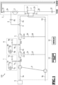
- Fig. 1 is a block diagram showing a configuration of a blood purification apparatus 100 according to a first embodiment.
- the blood purification apparatus 100 includes a blood purifier 1, a blood circuit 2, a dialysate circuit 3, a rehydration circuit 4, a blood pump 5, a dialysate supplier 6, a primary air introducer 7, a secondary air introducer 8, a dual pump 9, a dialysate filter 10, a dialysate filter 11, a controller 12, and a backup power source 13 as main constituents.
- a chamber for trapping bubbles of the blood flowing in the blood circuit 2 a water removal line and a water removal pump for removing water from the blood of a patient, and the like are also provided in reality.
- the blood purifier 1 which is also referred to as a dialyzer, purifies blood of a patient.
- the blood purifier 1 includes a blood introduction inlet 1a that introduces the blood from the blood circuit 2, and a blood introduction outlet 1b that discharges the purified blood.
- the blood purifier 1 includes a dialysate introduction inlet 1c that introduces a dialysate from the dialysate circuit 3, and a dialysate drainage outlet 1d that drains the dialysate (drainage).
- the blood purifier 1 includes a blood purification membrane that is provided inside.
- the blood purification membrane is formed from a bundle of hollow fibers having pores on side surfaces (a hollow fiber membrane). An inner side of the blood purification membrane is a blood flow route (not shown) and an outer side of the blood purification membrane (the hollow fibers) is a dialysate flow route (not shown).
- the blood to flow in the blood purifier 1 flows in the blood flow route and unwanted substances such as uremic substances are removed by passing through the pores in the blood purification membrane by one or both of diffusion and ultrafiltration.
- the dialysate to flow in the blood purifier 1 flows in the dialysate flow route and the blood is supplemented only with substances such as electrolytes included in the dialysate, which are necessary for a human body.
- the inner side of the blood purification membrane can also function as the dialysate flow route and the outer side of the blood purification membrane can also function as the blood flow route.
- the blood circuit 2 and the dialysate circuit 3 are coupled to each other through the blood purification membrane of the blood purifier 1, and are configured to bidirectionally circulate the blood and the dialysate.
- the blood circuit 2 is a flow route that introduces the blood removed from the patient into the blood purifier 1 and returns the blood discharged from the blood purifier 1 (the purified blood) to the body (the blood flows in a direction indicated with an arrow A in Fig. 1 ) at the time of a dialysis treatment.
- the blood circuit 2 is mainly formed from a tube that enables passage of the blood.
- the blood circuit 2 includes a blood removal side circuit 2a and a blood return side circuit 2b.
- the blood removal side circuit 2a is a flow route that introduces the blood removed from the patient into the blood purifier 1.
- One end of the blood removal side circuit 2a is attached to a blood removal side puncture needle (not shown) that is punctured into a blood vessel of the patient, and another end thereof is joined to the blood introduction inlet 1a.
- An on-off valve (a solenoid valve) V1 is provided to the blood removal side circuit 2a.
- a flow of the blood in the blood removal side circuit 2a is controlled by opening and closing the on-off valve V1.
- the blood return side circuit 2b is a flow route that returns the blood discharged from the blood purifier 1 to the body.
- One end of the blood return side circuit 2b is attached to a blood return side puncture needle (not shown) that is punctured into a blood vessel of the patient, and another end thereof is joined to the blood introduction outlet 1b.
- An on-off valve (a solenoid valve) V2 is provided to the blood return side circuit 2b. A flow of the blood in the blood return side circuit is controlled by opening and closing the on-off valve V2.
- the blood pump 5 is provided to the blood removal side circuit 2a and configured to deliver a liquid in the blood circuit 2 in a direction of movement from the blood removal side circuit 2a to the blood return side circuit 2b (hereinafter referred to as a normal direction in delivering liquid) or in a direction of movement from the blood return side circuit 2b to the blood removal side circuit 2a (hereinafter referred to as a reverse direction in delivering liquid).
- the blood pump 5 is formed from a peristaltic pump that includes a stator and a rotor, and the peristaltic pump is driven in such a way as to rotate the rotor.
- the rotor is rotated by an actuator (not shown) such as an electric motor under control of the controller 12.
- the blood pump 5 is provided with a rotary encoder (not shown).
- the rotary encoder detects the number of rotations of the rotor.
- the dialysate circuit 3 is a flow route that supplies the dialysate to the blood purifier 1 and/or the blood circuit 2, and discharges the drainage of the dialysate from the blood purifier 1.
- the dialysate circuit 3 is mainly formed from a tube that enables passage of the dialysate.
- the dialysate circuit 3 includes a dialysate introduction circuit 3a, a dialysate drainage circuit 3b, a dialysate bypass circuit 3c, and a dialysate bypass circuit 3d.
- the dialysate introduction circuit 3a is a flow route from the dialysate supplier 6 to the dialysate introduction inlet 1c.
- the dialysate flows in the blood purifier 1 by way of the dialysate introduction circuit 3a.
- An on-off valve (a solenoid valve) V3, an on-off valve (a solenoid valve) V4, and a dialysate port P are provided to the dialysate introduction circuit 3a.
- a flow of the dialysate into the blood purifier 1 is controlled by opening and closing the on-off valve V3 and the on-off valve V4.
- the dialysate port P takes out the dialysate.
- the dialysate drainage circuit 3b is a flow route from the dialysate drainage outlet 1d to a dialysate drainer (not shown).
- the drainage from the blood purifier 1 is drained to the dialysate drainer by way of the dialysate drainage circuit 3b.
- An on-off valve (a solenoid valve) V6 is provided to the dialysate drainage circuit 3b. A flow of the drainage to the dialysate drainer is controlled by opening and closing the on-off valve V6.
- Each of the dialysate bypass circuit 3c and the dialysate bypass circuit 3d is a flow route from the dialysate introduction circuit 3a to the dialysate drainage circuit 3b.
- An on-off valve (a solenoid valve) V7 is provided to the dialysate bypass circuit 3c.
- an on-off valve (a solenoid valve) V8 is provided to the dialysate bypass circuit 3d.
- a flow of the dialysate from the dialysate introduction circuit 3a to the dialysate drainage circuit 3b is controlled by opening and closing the on-off valves V7 and V8.
- the dialysate bypass circuit 3c and the dialysate bypass circuit 3d are the flow routes for preventing the inappropriate dialysate from flowing into the blood circuit 2.
- the blood purification apparatus 100 is provided with a warmer (not shown) for warming the dialysate.
- the dialysate flows to the dialysate drainage circuit 3b through the dialysate bypass circuit 3c and/or the dialysate bypass circuit 3d in order to prevent the dialysate at the high temperature from flowing to the blood circuit 2.
- the on-off valve V7 and/or the on-off valve V8 are opened.
- the rehydration circuit 4 is a connection flow route that connects the blood circuit 2 to the dialysate circuit 3 while bypassing the blood purifier 1.
- the rehydration circuit 4 is a flow route from the dialysate port P to the blood removal side circuit 2a for supplying the dialysate from the dialysate circuit 3 to the blood circuit 2 while bypassing the blood purifier 1.
- An on-off valve (a solenoid valve) V5 is provided to the rehydration circuit 4. A flow of the dialysate to the blood removal side circuit 2a is controlled by opening and closing the on-off valve V5.
- the dialysate supplier 6 introduces the dialysate into the dialysate introduction circuit 3a.
- the dialysate supplier 6 receives supply of pure water from a not-illustrated pure water machine (an RO water machine) provided outside the blood purification apparatus 100, and receives supply of (suctions) an undiluted solution from a not-illustrated undiluted solution tank externally mounted on the blood purification apparatus 100. Subsequently, the dialysate supplier 6 produces the dialysate by mixing the undiluted solution of the dialysate with the pure water in a predetermined proportion, and introduces the dialysate into the dialysate introduction circuit 3a.
- the blood purification apparatus 100 includes the dialysate supplier 6.
- the dialysate supplier 6 may be externally provided as a dialysate supply apparatus, and the blood purification apparatus may receive the supply of the dialysate from the dialysate supply apparatus.
- the dialysate supplier 6 While the dialysate supplier 6 generates the dialysate and introduces the dialysate into the dialysate introduction circuit 3a at normal times (such as at the time of the dialysis treatment), generation of the new dialysate may be restricted in the event of a blackout and the like. In this case, the supply of the dialysate from the dialysate supplier 6 to the dialysate circuit 3 is stopped and the dialysate stored in the dialysate filter 10 and/or the dialysate filter 11 is introduced into the dialysate circuit 3 instead. Details will be described later.
- the primary air introducer 7 introduces the air into the (primary) dialysate filter 10 to be described later.
- the air is introduced into the dialysate filter 10 by the primary air introducer 7.
- the dialysate filter 10 is set to a positive pressure and the dialysate stored in the dialysate filter 10 flows to the dialysate circuit 3 (the dialysate port P).
- the primary air introducer 7 plays roles in pushing the dialysate stored in the dialysate filter 10 out to the dialysate circuit 3, and feeding the dialysate to the dialysate circuit 3 (the dialysate introduction circuit 3a) and the blood circuit 2.
- the primary air introducer 7 includes an air pump 7a, an air introduction route 7b, an on-off valve (a solenoid valve) 7c, an air filter 7d, and an air filter 7e.
- the air pump 7a incorporates a rotor and drives the rotor so as to perform rotation.
- the rotor is rotated by an actuator (not shown) such as an electric motor under control of the controller 12.
- the air pump 7a is provided with a rotary encoder (not shown). The rotary encoder detects the number of rotations of the rotor. By the rotation of the air pump 7a, the air is introduced into the dialysate filter 10 through the air introduction route 7b.
- the air introduced into the dialysate filter 10 by the drive of the air pump 7a generates a flow of the dialysate to the dialysate circuit 3 (the dialysate introduction circuit 3a) and the blood circuit 2.
- the flow of the air to the dialysate filter 10 is controlled by opening and closing the on-off valve 7c provided between the air pump 7a and the dialysate filter 10.
- the air filter 7d and the air filter 7e remove dust in the air.
- the secondary air introducer 8 introduces the air into the (secondary) dialysate filter 11 to be described later.
- the air is introduced into the dialysate filter 11 by the secondary air introducer 8.
- the dialysate filter 11 is set to a positive pressure and the dialysate stored in the dialysate filter 11 flows to the dialysate circuit 3 (the dialysate port P).
- the secondary air introducer 8 plays roles in pushing the dialysate stored in the dialysate filter 11 out to the dialysate circuit 3, and in feeding the dialysate to the dialysate circuit 3 (the dialysate introduction circuit 3a) and the blood circuit 2.
- the secondary air introducer 8 includes an air pump 8a, an air introduction route 8b, an on-off valve (a solenoid valve) 8c, an air filter 8d, and an air filter 8e.
- the air pump 8a incorporates a rotor and drives the rotor so as to perform rotation.
- the rotor is rotated by an actuator (not shown) such as an electric motor under control of the controller 12.
- the air pump 8a is provided with a rotary encoder (not shown). The rotary encoder detects the number of rotations of the rotor. By the rotation of the air pump 8a, the air is introduced into the dialysate filter 11 through the air introduction route 8b.
- the air introduced into the dialysate filter 11 by the drive of the air pump 8a generates a flow of the dialysate to the dialysate circuit 3 (the dialysate introduction circuit 3a) and the blood circuit 2.
- the flow of the air to the dialysate filter 11 is controlled by opening and closing the on-off valve 8c provided between the air pump 8a and the dialysate filter 11.
- the air filter 8d and the air filter 8e remove dust in the air.
- the on-off valve 7c, the air filter 7d, and the air filter 7e are not essential structures in the primary air introducer 7.
- the on-off valve 8c, the air filter 8d, and the air filter 8e are not essential structures in the secondary air introducer 8.
- the dual pump 9 is provided across the dialysate introduction circuit 3a and the dialysate drainage circuit 3b.
- the dual pump 9 introduces the dialysate to a downstream side in a liquid delivery direction of the dialysate introduction circuit 3a, and meanwhile, discharges the drainage of the dialysate to a downstream side in the liquid delivery direction of the dialysate drainage circuit 3b.
- the dual pump 9 plays roles as a dialysate supply pump for supplying the dialysate to the blood circuit 2 and as a dialysate drainage pump for draining the dialysate from the dialysate drainer.
- a plunger (not shown) is provided inside a housing of the dual pump 9.
- a volume on the dialysate introduction circuit 3a side and a volume on the dialysate drainage circuit 3b side are defined while interposing the plunger in between, and the introduction of the dialysate and the discharge of the drainage are interlocked with reciprocation of the plunger.
- the dialysate filter 10 purifies the dialysate by trapping substances such as endotoxins contained in the dialysate supplied from the dialysate supplier 6.
- the dialysate filter 10 is provided to the dialysate circuit 3, and includes a primary chamber 10a and a secondary chamber 10b. Meanwhile, a dialysate purification membrane is provided inside the dialysate filter 10.
- the dialysate purification membrane is formed from a bundle of hollow fibers (a hollow fiber membrane) with side walls provided with pores.
- the dialysate filter 10 is configured such that the dialysate flows from the primary chamber 10a (an inner side of the dialysate purification membrane) to the secondary chamber 10b (an outer side of the dialysate purification membrane).
- the dialysate filter 10 has a property of blocking passage of the air with surface tension of water molecules by passing water thereto.
- the primary chamber 10a and the secondary chamber 10b can store the dialysate supplied from the dialysate supplier 6.
- the dialysate to be purified is stored in the primary chamber 10a while the purified dialysate is stored in the secondary chamber 10b.
- the stored dialysate is supplied to the dialysate circuit 3 by the primary air introducer 7 as described later.
- the primary chamber 10a may be located on the outer side of the dialysate purification membrane and the secondary chamber 10b may be located on the inner side of the dialysate purification membrane.
- the dialysate filter 11 purifies the dialysate by trapping the substances such as endotoxins contained in the dialysate supplied from the dialysate supplier 6.
- the dialysate filter 11 is provided to the dialysate circuit 3, and includes a primary chamber 11a and a secondary chamber 11b. Meanwhile, a dialysate purification membrane is provided inside the dialysate filter 11.
- the dialysate purification membrane is formed from a bundle of hollow fibers (a hollow fiber membrane) with side walls provided with pores.
- the dialysate filter 11 is configured such that the dialysate flows from the primary chamber 11a (an inner side of the dialysate purification membrane) to the secondary chamber 11b (an outer side of the dialysate purification membrane).
- the dialysate filter 11 has a property of blocking passage of the air with surface tension of water molecules by passing water thereto.
- the primary chamber 11a and the secondary chamber 11b can store the dialysate supplied from the dialysate supplier 6.
- the dialysate to be purified is stored in the primary chamber 11a while the purified dialysate is stored in the secondary chamber 11b.
- the stored dialysate is supplied to the dialysate circuit 3 by the secondary air introducer 8 as described later.
- the primary chamber 11a may be located on the outer side of the dialysate purification membrane and the secondary chamber 11b may be located on the inner side of the dialysate purification membrane.
- the filters such as the dialysate filter 10 and the dialysate filter 11 are generally provided to the blood purification apparatus in order to remove impurities contained in the dialysate at the time of the dialysis treatment.
- the pair of the dialysate filter 10 and the dialysate filter 11 are provided to the dialysate circuit 3, so that the dialysate can be purified even in the case where one of the filters fails to function.
- the controller 12 is a processing device that controls the entire blood purification apparatus 100 including the air pump 7a and the air pump 8a mentioned above, and so forth.
- the controller 12 includes an arithmetic device and a storage device (a storage device such as a RAM and a ROM).
- the arithmetic device may be implemented by a processor such as a CPU and a microcontroller, an ASIC (application specific integrated circuit), an FPGA (field programmable gate array), and the like, but its mode is not limited.
- the backup power source 13 is a power unit that supplies electric power to some of the constituents such as the controller 12 in the case where power supply from the main power source (not shown) to the blood purification apparatus 100 is stopped due to blackout and the like, for example.
- the controller 12, the primary air introducer 7, the secondary air introducer 8, and the like function so that the blood remaining in the blood circuit 2 can be returned to the body.
- the dialysate from the dialysate supplier 6 is introduced into the dialysate introduction circuit 3a by operating the dual pump 9 at the time of the dialysis treatment, and the dialysate is passed from the dialysate circuit 3 to the rehydration circuit 4, thus flowing in the blood purifier 1.
- the dialysate is passed from the blood purifier 1 to the dialysate drainage circuit 3b, and is discharged from the dialysate drainer.
- the blood flows in the normal direction in delivering liquid by the forward rotation of the blood pump 5. Due to the flow of the dialysate at the time of the dialysis treatment mentioned above, the purified dialysate is stored in the dialysate filter 10 and the dialysate filter 11.
- Fig. 2 shows a state where the air pump 7a and the air pump 8a function as the liquid level adjustment pumps.
- the air pump 7a, the air pump 8a, and the liquid level adjustment pump may be provided independently of one another.
- a blood removal side air trap chamber 2c is provided to the blood removal side circuit 2a, and a blood return side air trap chamber 2d is provided to the blood return side circuit 2b.
- the blood removal side air trap chamber 2c is provided mainly for the purpose of trapping the air so as not to cause the air to flow into the blood purifier 1 and to develop air lock.
- the blood return side air trap chamber 2d is provided mainly for the purpose of trapping the air so as not to cause the air to flow into the body of the patient through the blood circuit 2. It is not always necessary to provide both of the blood removal side air trap chamber 2c and the blood return side air trap chamber 2d, and only one of them may be provided. In other words, the blood removal side air trap chamber 2c and the blood return side air trap chamber 2d play roles as chambers to contain the blood in the blood circuit 2.
- the blood removal side air trap chamber 2c is coupled to the secondary air introducer 8 and an on-off valve (a solenoid valve) V9 is provided therebetween.
- the flow of the air from the secondary air introducer 8 to the blood removal side air trap chamber 2c is controlled by opening and closing the on-off valve V9 (the secondary air introducer 8 causes the air to flow to the blood removal side air trap chamber 2c).
- the blood return side air trap chamber 2d is coupled to the primary air introducer 7 and an on-off valve (a solenoid valve) V10 is provided therebetween.
- the flow of the air from the primary air introducer 7 to the blood return side air trap chamber 2d is controlled by opening and closing the on-off valve V10 (the primary air introducer 7 causes the air to flow to the blood return side air trap chamber 2d).
- Each of the blood removal side air trap chamber 2c and the blood return side air trap chamber 2d includes two layers, namely, a blood layer and an air layer.
- the liquid level moves down as the air is accumulated in the chamber, which may lead to the occurrence of the air lock in which the air enters the hollow fibers in the blood purifier 1.
- the primary air introducer 7 (the air pump 7a) rotates forward so as to introduce the air into the blood return side air trap chamber 2d and to move down the liquid level, or rotates in reverse so as to discharge the air from the blood return side air trap chamber 2d and to move up the liquid level.
- the secondary air introducer 8 (the air pump 8a) rotates forward so as to introduce the air into the blood removal side air trap chamber 2c and to move down the liquid level, or rotates in reverse so as to discharge the air from the blood removal side air trap chamber 2c and to move up the liquid level.
- Fig. 2 shows the example in which the blood removal side air trap chamber 2c is coupled to the secondary air introducer 8 and the blood return side air trap chamber 2d is coupled to the primary air introducer 7.
- this mode of connection is merely an example.
- the blood removal side air trap chamber 2c may be coupled to the primary air introducer 7 and the blood return side air trap chamber 2d may be coupled to the secondary air introducer 8.
- both of the blood removal side air trap chamber 2c and the blood return side air trap chamber 2d may be coupled to either the primary air introducer 7 or the secondary air introducer 8.
- the dialysate supplier 6 stops the generation and supply of the dialysate.
- the air pump 7a plays a role in feeding the dialysate in the dialysate filter 10 to the blood circuit 2 instead of adjusting the liquid level in the blood return side air trap chamber 2d.
- the air pump 8a plays a role in feeding the dialysate in the dialysate filter 11 to the blood circuit 2 instead of adjusting the liquid level in the blood removal side air trap chamber 2c.
- the first embodiment adopts the blood return method of returning the blood to the body by introducing the dialysate from the dialysate circuit 3 to the blood circuit 2 through the blood purification membrane of the blood purifier 1 and causing the dialysate to push out the blood in the blood purifier 1 and the blood circuit 2.
- this blood return method will be referred to as a back filtration based blood return process.
- the dialysate flows in the dialysate circuit 3 and passes from the dialysate circuit 3 to the blood purifier 1. This flow of the dialysate causes the dialysate to pass through the dialysate flow route of the blood purifier 1, whereby the dialysate pushes out the blood through the pores in the blood purification membrane, thus returning the blood to the body.
- Fig. 3 shows a flow of the dialysate in the case where the back filtration based blood return process is carried out by using the dialysate in the dialysate filter 10.
- the blood is returned to the body in the normal direction in delivering liquid in the back filtration based blood return process.
- valves among the valves (V1 to V6, V7c, and V8c) in the drawings are indicated with hatching in the case where the valves are opened, and the valves in the drawings are indicated with outlines in the case where the valves are closed.
- the on-off valve 7c, the on-off valve V3, the on-off valve V4, and the on-off valve V2 are opened in the back filtration based blood return process (the normal direction in delivering liquid). Meanwhile, the air pump 7a rotates forward.
- the opening of these on-off valves and the rotation of the air pump 7a are controlled by instructions of the controller 12.
- the controller 12 controls the number of rotations of the air pump 7a per unit time in such a way as to generate the flow of the dialysate to the dialysate circuit 3 (the dialysate introduction circuit 3a) and the blood circuit 2.
- the controller 12 controls a flow rate of the air from the primary air introducer 7.
- the on-off valve V10 shown in Fig. 2 is closed.
- the air pump 7a and opening the on-off valve 7c By driving the air pump 7a and opening the on-off valve 7c, the air is introduced into the dialysate filter 10 and the primary chamber 10a of the dialysate filter 10 is set to the positive pressure. Accordingly, the dialysate in the primary chamber 10a reaches the secondary chamber 10b and flows in the dialysate introduction circuit 3a. In other words, the controller 12 controls the dialysate circuit 3 and the blood circuit 2 such that the dialysate flows in the flow route shown in Fig. 3 .
- the dialysate By opening the on-off valve V3, the on-off valve V4, and the on-off valve V2, the dialysate passes through the dialysate introduction circuit 3a, the blood purifier 1 (the blood purification membrane), and the blood return side circuit 2b.
- this flow of the dialysate is indicated with an arrow of a thick chain line.
- the dialysate flows inside the blood purifier 1 in the order of the dialysate flow route, the blood purification membrane, and the blood flow route.
- the dialysate pushes out the blood remaining in the blood purifier 1 and the blood circuit 2 (the blood return side circuit 2b), and the blood is returned to the body.
- the back filtration based blood return process (the normal direction in delivering liquid) described with reference to Fig. 3 is carried out by operating at least the controller 12, the on-off valve 7c, the on-off valve V3, the on-off valve V4, the on-off valve V2, and the air pump 7a only by the power supply from the backup power source 13.
- the constituents such as the blood pump 5 and the dual pump 9 for feeding the dialysate to the dialysate circuit 3 and feeding the blood to the blood circuit 2 in the dialysis treatment may be stopped.
- the process is switched to the back filtration based blood return process (the normal direction in delivering liquid) using the dialysate in the dialysate filter 11.
- the back filtration based blood return process (the normal direction in delivering liquid)
- a supply source of the dialysate is switched from the dialysate filter 10 to the dialysate filter 11. This switching is carried out by the controller 12, and details thereof will be described later.
- Fig. 4 shows a flow of the dialysate in the case of carrying out the back filtration based blood return process (the normal direction in delivering liquid) by using the dialysate in the dialysate filter 11.
- the on-off valve 7c is closed and the air pump 7a stops the rotation. Meanwhile, the air pump 8a rotates forward and the on-off valve 8c is opened.
- the opening and closing of these on-off valves, the stop of the rotation of the air pump 7a, and the rotation of the air pump 8a are controlled by instructions of the controller 12.
- the controller 12 controls the number of rotations of the air pump 8a per unit time in such a way as to generate the flow of the dialysate to the dialysate circuit 3 (the dialysate introduction circuit 3a) and the blood circuit 2.
- the controller 12 controls a flow rate of the air from the secondary air introducer 8.
- the on-off valve V9 shown in Fig. 2 is closed.
- the air pump 8a and opening the on-off valve 8c By driving the air pump 8a and opening the on-off valve 8c, the air is introduced into the dialysate filter 11 and the primary chamber 1 1a of the dialysate filter 11 is set to the positive pressure. Accordingly, the dialysate in the primary chamber 11a reaches the secondary chamber 11b and flows in the dialysate introduction circuit 3a. Thereafter, the dialysate flows in the same flow route as the flow route shown in Fig. 3 . In other words, the controller 12 controls the dialysate circuit 3 and the blood circuit 2 such that the dialysate flows in the flow route shown in Fig. 4 . In Fig. 4 , this flow of the dialysate is indicated with an arrow of a thick chain line.
- the back filtration based blood return process (the normal direction in delivering liquid) described with reference to Fig. 4 is carried out by operating at least the controller 12, the on-off valve 8c, the on-off valve V3, the on-off valve V4, the on-off valve V2, and the air pump 8a only by the power supply from the backup power source 13.
- the blood pump 5, the dual pump 9, and the like may be stopped.
- the controller 12 determines that the dialysate in the dialysate filter 10 is introduced into (pushed out to) the dialysate circuit 3. This determination may be carried out by detecting that the primary chamber 10a is set to the positive pressure. In this case, a pressure gauge is provided to the primary chamber 10a and the pressure gauge detects a pressure of the air. The detected pressure value is transmitted to the controller 12. The controller 12 determines whether or not the pressure value exceeds a predetermined threshold.
- the determination may be carried out by detecting that bubbles are generated in the dialysate in the primary chamber 10a, because in the case where the air is introduced into the primary chamber 10a, the bubbles may be generated by the air that is mixed into the dialysate in the primary chamber 10a.
- an ultrasonic sensor is provided to the primary chamber 10a, for example, and the ultrasonic sensor detects a voltage corresponding to vibration of the dialysate.
- the bubbles have a higher attenuation rate than that of the dialysate. Accordingly, the generation of the bubbles can be detected by determining that the voltage value exceeds a predetermined threshold.
- the detected voltage value is transmitted to the controller 12.
- the controller 12 determines whether or not the voltage value exceeds a predetermined threshold.
- the determination may be carried out by measuring a temperature of the air introduced from the primary air introducer 7 and a temperature of a flow route (from the primary air introducer 7 to the dialysate filter 10) of the dialysate introduction circuit 3a, and determining whether or not the temperature of the dialysate introduction circuit 3a falls within a predetermined range based on the temperature of the introduced air. Because, in a case where a predetermined amount of the air is introduced to the dialysate filter 10, the temperature of the flow route comes close to the temperature of the introduced air.
- a thermometer is provided at an inlet of the primary air introducer 7, for example, and the thermometer measures the temperature of the air introduced from the primary air introducer 7.
- thermometer is also provided at the flow route between the primary air introducer 7 and the dialysate filter 10, and the thermometer detects the temperature of the flow route. Both of the detected temperature values are transmitted to the controller 12. The controller 12 determines whether or not each temperature value falls within a predetermined range.
- the determination may be carried out by determining whether or not the dialysate that flows in the dialysate introduction circuit 3a reaches a predetermined amount (such as a volume of the dialysate filter 10 (the primary chamber 10a and the secondary chamber 10b)).
- a flowmeter is provided to the dialysate introduction circuit 3a and the flowmeter measures a flow rate of the dialysate flowing in the dialysate introduction circuit 3a.
- the detected flow rate value is transmitted to the controller 12.
- the controller 12 determines whether or not the flow rate value reaches a predetermined amount.
- the blood return is carried out by using the dialysate in the two dialysate filters (the dialysate filter 10 and the dialysate filter 11).
- the supply source of the dialysate is switched from the dialysate filter 10 to the dialysate filter 11 in the case where it is not possible to return the blood sufficiently only with the dialysate in the dialysate filter 10.
- the two dialysate filters are provided to the dialysate circuit 3 from a fail-safe point of view and are designed such that the amount of the dialysate that remains in the two dialysate filters corresponds to the amount of the blood that remains in the blood circuit 2.
- the number of the dialysate filters is not limited only to two.
- a single dialysate filter may be designed such that the amount of the dialysate remaining therein corresponds to the amount of the blood remaining in the blood circuit 2, and the blood return may be carried out likewise by introducing the air into the single dialysate filter only.
- the back filtration based blood return process (the normal direction in delivering liquid) is carried out by using the dialysate in the dialysate filter 10 and the dialysate filter 11.
- the introduction of the air into the filter through the air introduction line does not bring about the flow of the dialysate to the blood circuit, and the dialysate in the filter is drawn out to the blood circuit by driving the blood pump. Therefore, the blood purification apparatus described in PTL 1 has to drive the blood pump.
- a portion of the circuit on the inlet side of the blood pump may be set to a negative pressure due to a pressure generated by the rotation of the blood pump for drawing out the dialysate in the blood circuit.
- the negative pressure in the blood circuit may cause burst of blood cell components (hemolysis) of the blood located inside and/or deterioration in ejection accuracy of the blood pump.
- the dialysate in the dialysate filter 10 flows to the dialysate circuit 3 and the blood circuit 2 by driving the air pump 7a. It is therefore not necessary to drive the blood pump 5 in order to draw out the dialysate. Moreover, in the configuration of the first embodiment, no pressure is generated in the blood circuit 2 for drawing out the dialysate, and the blood circuit 2 is hence not set to the negative pressure. The same applies to the case of using the dialysate in the dialysate filter 11. Therefore, according to the configuration of the first embodiment, it is possible to carry out the blood return more favorably as compared to the related art even in the case where the dialysate supplier 6 stops the generation and the supply of the dialysate.
- the controller 12, the on-off valve 7c, the on-off valve V3, the on-off valve V4, the on-off valve V2, and the air pump 7a are operated in the configuration according to the first embodiment. From this perspective, it is possible to carry out the blood return by the power supply from the backup power source 13 to the minimum required constituents particularly in the case where the power supply from the main power source to the blood purification apparatus 100 is stopped.
- the blood pump 5 may be driven by also supplying the power from the backup power source 13 to the blood pump 5.
- the flows of the blood and the dialysate in the normal direction in delivering liquid are generated in the blood circuit 2. Accordingly, the blood pump 5 rotates forward. In other words, a pressure for drawing out the dialysate is generated in the blood circuit 2.
- the pressure in the dialysate circuit 3 caused by the introduction of the air into the dialysate filter 10 (or the dialysate filter 11) is controlled not to exceed a predetermined threshold.
- This threshold may be an experimentally obtained value for keeping the blood circuit 2 from being set to the negative pressure (or keeping the blood in the blood circuit 2 from being hemolyzed).
- the pressure in the dialysate circuit 3 generated by the introduction of the air into the dialysate filter 10 (or the dialysate filter 11) may be controlled such that the pressure becomes higher than a pressure in the blood circuit 2 generated by driving the blood pump 5.
- the above-mentioned control may be carried out by performing control so as to rotate the air pump 7a and the blood pump 5 at predetermined numbers of rotations per unit time (to rotate the air pump 7a at a higher number of rotations per unit time than that of the blood pump 5, for example) such that the pressure in the dialysate circuit 3 does not exceed the threshold (or becomes higher than the pressure in the blood circuit 2), for example.
- the predetermined numbers of rotations may be experimentally obtained values.
- the encoders detect the number of rotations of the air pump 7a and the number of rotations of the blood pump 5.
- the detected numbers of rotations are transmitted to the controller 12. Based on the detected numbers of rotations, the controller 12 controls the air pump 7a and the blood pump 5 in such a way as to rotate the pumps at the predetermined numbers of rotations.
- control may be carried out by performing control so as to rotate the air pump 8a and the blood pump 5 at predetermined numbers of rotations per unit time (to rotate the air pump 8a at a higher number of rotations per unit time than that of the blood pump 5, for example) such that the pressure in the dialysate circuit 3 does not exceed the threshold (or becomes higher than the pressure in the blood circuit 2), for example.
- the encoders detect the number of rotations of the air pump 8a and the number of rotations of the blood pump 5.
- the detected numbers of rotations are transmitted to the controller 12. Based on the detected numbers of rotations, the controller 12 controls the air pump 8a and the blood pump 5 in such a way as to rotate the pumps at the predetermined numbers of rotations.
- control may be carried out by controlling the number of rotations of the air pump 7a per unit time (or the number of rotations of the air pump 8a per unit time) and the number of rotations of the blood pump 5 per unit time based on the pressure in the dialysate circuit 3 and the pressure in the blood circuit 2.
- a pressure gauge is provided to the dialysate circuit 3 and the pressure gauge detects a pressure in the dialysate circuit 3.
- another pressure gauge is provided to the blood circuit 2 and the pressure gauge detects a pressure in the blood circuit 2. The detected pressure values are transmitted to the controller 12, respectively.
- the controller 12 controls both of them so as to increase the number of rotations of the air pump 7a per unit time (or the number of rotations of the air pump 8a per unit time), and/or to decrease the number of rotations of the blood pump 5 per unit time.
- a back filtration based blood return process (the reverse direction in delivering liquid) to return the blood to the body in the reverse direction in delivering liquid may be carried out instead of or in addition to the blood return process described with reference to Figs. 3 and 4 .
- Fig. 5 shows a flow of the dialysate in the case of carrying out the back filtration based blood return process (the reverse direction in delivering liquid) by using the dialysate in the dialysate filter 10.
- the on-off valve 7c, the on-off valve V3, the on-off valve V4, and the on-off valve V1 are opened in the back filtration based blood return process (the reverse direction in delivering liquid). Meanwhile, the air pump 7a rotates forward. Moreover, the blood pump 5 rotates in reverse. The opening of these on-off valves, the rotation of the air pump 7a, and the rotation of the blood pump 5 are controlled by instructions of the controller 12.
- the controller 12 controls the number of rotations of the air pump 8a per unit time (controls the flow rate of the air in the secondary air introducer 8) in such a way as to generate the flow of the dialysate to the dialysate circuit 3 (the dialysate introduction circuit 3a) and the blood circuit 2.
- the air pump 7a and opening the on-off valve 7c By driving the air pump 7a and opening the on-off valve 7c, the air is introduced into the dialysate filter 10 and the primary chamber 10a of the dialysate filter 10 is set to the positive pressure. Accordingly, the dialysate in the primary chamber 10a reaches the secondary chamber 10b and flows in the dialysate introduction circuit 3a. In other words, the controller 12 controls the dialysate circuit 3 and the blood circuit 2 such that the dialysate flows in the flow route shown in Fig. 5 .
- the dialysate By opening the on-off valve V3, the on-off valve V4, and the on-off valve V1, the dialysate passes through the dialysate introduction circuit 3a, the blood purifier 1 (the blood purification membrane), and the blood removal side circuit 2a.
- this flow of the dialysate is indicated with an arrow of a thick chain line.
- the dialysate flows inside the blood purifier 1 in the order of the dialysate flow route, the blood purification membrane, and the blood flow route.
- the dialysate pushes out the blood remaining in the blood purifier 1 and the blood circuit 2 (the blood removal side circuit 2a), and the blood is returned to the body.
- the back filtration based blood return process (the reverse direction in delivering liquid) described with reference to Fig. 5 is carried out by operating at least the controller 12, the on-off valve 7c, the on-off valve V3, the on-off valve V4, the on-off valve V1, the air pump 7a, and the blood pump 5 only by the power supply from the backup power source 13.
- the constituents such as the dual pump 9 for feeding the dialysate to the dialysate circuit 3 in the dialysis treatment may be stopped.
- the supply source of the dialysate is switched from the dialysate filter 10 to the dialysate filter 11.
- the switching of the supply source of the dialysate has been described with reference to Figs. 3 and 4 , and detailed explanations thereof will be omitted.
- the back filtration based blood return process (the reverse direction in delivering liquid) is carried out by using the dialysate in the dialysate filter 11.
- the blood pump 5 is driven in the back filtration based blood return process (the reverse direction in delivering liquid). Accordingly, the air pump 7a (or the air pump 8a) and the blood pump 5 are controlled such that the pressure in the dialysate circuit 3 becomes higher than the pressure in the blood circuit 2. This control has been described with reference to Figs. 3 and 4 , and detailed explanations thereof will be omitted.
- both of the back filtration based blood return process (the normal direction in delivering liquid) and the back filtration based blood return process (the reverse direction in delivering liquid) may be carried out.
- the back filtration based blood return process (the normal direction in delivering liquid) may be carried out in the first place by using the dialysate in the dialysate filter 10, and the back filtration based blood return process (the reverse direction in delivering liquid) may be carried out by using the dialysate in the dialysate filter 11 in the case of switching the supply source of the dialysate.
- the back filtration based blood return process (the reverse direction in delivering liquid) may be carried out in the first place by using the dialysate in the dialysate filter 10, and the back filtration based blood return process (the normal direction in delivering liquid) may be carried out by using the dialysate in the dialysate filter 11 in the case of switching the supply source of the dialysate.
- the back filtration based blood return process (the normal direction in delivering liquid)
- the back filtration based blood return process (the reverse direction in delivering liquid) it is possible to return the blood remaining in both of the blood removal side circuit 2a and the blood return side circuit 2b to the body.
- Fig. 6 is a block diagram showing a configuration of a blood purification apparatus 200 according to a second embodiment.
- the blood purification apparatus 200 has a different configuration of the rehydration circuit 4 and the configurations of the rest are the same.
- the rehydration circuit 4 of the blood purification apparatus 100 is the flow route from the dialysate port P to the blood removal side circuit 2a.
- the rehydration circuit 4 of the blood purification apparatus 200 includes a blood removal side rehydration circuit 4a and a blood return side rehydration circuit 4b.
- the blood removal side rehydration circuit 4a corresponds to the rehydration circuit 4 of the blood purification apparatus 100.
- the blood return side rehydration circuit 4b is a flow route from the dialysate port P to the blood return side circuit 2b for returning the blood in the blood circuit 2 to the body by a rehydration based blood return process (the reverse direction in delivering liquid) to be described later.
- An on-off valve (a solenoid valve) V11 is provided to the blood return side rehydration circuit 4b. The flow of the dialysate to the blood return side circuit 2b is controlled by opening and closing the on-off valve V11.
- the dialysate in the dialysate filter 11 may also be used in the second embodiment as with the first embodiment. Specifically, in the case where the dialysate in the dialysate filter 10 flows, the supply source of the dialysate is switched from the dialysate filter 10 to the dialysate filter 11. Only some of the constituents to be described later function by the power supply from the backup power source 13 in the blood purification apparatus 200 as well.
- the second embodiment adopts the blood return method of returning the blood to the body by introducing the dialysate to the blood circuit 2 through the rehydration circuit 4 and causing the dialysate to push out the blood in the blood circuit 2.
- this blood return method will be referred to as the rehydration based blood return process.
- the dialysate flows in the dialysate circuit 3 and passes from the dialysate circuit 3 to the rehydration circuit 4 and the blood circuit 2.
- This flow of the dialysate causes the dialysate to flow in the blood circuit of the blood purifier 1, whereby the dialysate pushes out the blood remaining in the blood circuit 2 and the blood purifier 1, thus returning the blood to the body.
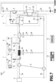
- Fig. 7 shows a flow of the dialysate in the case where the rehydration based blood return process is carried out by using the dialysate in the dialysate filter 10.
- the blood is returned to the body in the normal direction in delivering liquid in the rehydration based blood return process.
- Valves shown in the drawing are indicated with hatching. In the case where any of the valves is closed, the relevant valve shown in the drawing is indicated with an outline.
- the on-off valve 7c, the on-off valve V3, the on-off valve V5, and the on-off valve V2 are opened in the rehydration based blood return process (the normal direction in delivering liquid). Meanwhile, the air pump 7a rotates forward. Moreover, the blood pump 5 rotates forward. The opening of these on-off valves, the rotation of the air pump 7a, and the rotation of the blood pump 5 are controlled by instructions of the controller 12.
- the controller 12 controls the number of rotations of the air pump 7a per unit time (controls the flow rate of the air from the primary air introducer 7) in such a way as to generate the flow of the dialysate to the dialysate circuit 3 (the dialysate introduction circuit 3a), the rehydration circuit 4, and the blood circuit 2.
- the air pump 7a and opening the on-off valve 7c By driving the air pump 7a and opening the on-off valve 7c, the air is introduced into the dialysate filter 10 and the primary chamber 10a of the dialysate filter 10 is set to the positive pressure. Accordingly, the dialysate in the primary chamber 10a reaches the secondary chamber 10b and flows in the dialysate introduction circuit 3a.
- the controller 12 controls the dialysate circuit 3, the rehydration circuit 4, and the blood circuit 2 such that the dialysate flows in the flow route shown in Fig. 7 .
- the dialysate By opening the on-off valve V3, the on-off valve V5, and the on-off valve V2, the dialysate passes through the dialysate introduction circuit 3a, the blood removal side rehydration circuit 4a, the blood removal side circuit 2a, the blood purifier 1 (the blood flow route), and the blood return side circuit 2b.
- this flow of the dialysate is indicated with an arrow of a thick chain line.
- the dialysate pushes out the blood remaining in the blood purifier 1 and the blood circuit 2 (the blood return side circuit 2b), and the blood is returned to the body.
- the rehydration based blood return process (the normal direction in delivering liquid) described with reference to Fig. 7 is carried out by operating at least the controller 12, the on-off valve 7c, the on-off valve V3, the on-off valve V5, the on-off valve V2, the air pump 7a, and the blood pump 5 only by the power supply from the backup power source 13.
- the constituents such as the dual pump 9 for feeding the dialysate to the dialysate circuit 3 and feeding the blood to the blood circuit 2 in the dialysis treatment may be stopped.
- the supply source of the dialysate is switched from the dialysate filter 10 to the dialysate filter 11.
- the switching of the supply source of the dialysate has been described in the first embodiment, and detailed explanations thereof will be omitted.
- the rehydration based blood return process (the normal direction in delivering liquid) is carried out by using the dialysate in the dialysate filter 11.
- the rehydration based blood return process (the normal direction in delivering liquid) is carried out by using the dialysate in the dialysate filter 10.
- the dialysate in the dialysate filter 10 In the configuration according to the second embodiment, no pressure is generated in the blood circuit 2 for drawing out the dialysate, and the blood circuit 2 is hence not set to the negative pressure either.
- the dialysate in the dialysate filter 11 Therefore, according to the configuration of the second embodiment, it is possible to carry out the blood return more favorably as compared to the related art even in the case where the dialysate supplier 6 stops the generation and the supply of the dialysate.
- the controller 12, the on-off valve 7c, the on-off valve V3, the on-off valve V5, the on-off valve V2, the air pump 7a, and the blood pump 5 are operated in the configuration according to the second embodiment. From this perspective, it is possible to carry out the blood return by the power supply from the backup power source 13 to the minimum required constituents particularly in the case where the power supply from the main power source to the blood purification apparatus 100 is stopped.
- the dialysate passes through the blood pump 5 in the rehydration based blood return process (the normal direction in delivering liquid), and the blood pump 5 therefore has to be driven. Accordingly, the pressure for drawing out the dialysate is generated in the blood circuit 2.
- the air pump 7a (or the air pump 8a) and/or the blood pump 5 are controlled such that the pressure in the dialysate circuit 3 caused by the introduction of the air into the dialysate filter 10 (or the dialysate filter 11) does not exceed a predetermined threshold (or becomes higher than the pressure in the blood circuit 2 generated by driving the blood pump 5).
- This control has been described in the first embodiment and detailed explanations thereof will be omitted.
- a rehydration based blood return process (the reverse direction in delivering liquid) to return the blood to the body in the reverse direction in delivering liquid may be carried out instead of or in addition to the blood return process described with reference to Fig. 7 .
- Fig. 8 shows a flow of the dialysate in the case of carrying out the rehydration based blood return process (the reverse direction in delivering liquid) by using the dialysate in the dialysate filter 10.
- the on-off valve 7c, the on-off valve V3, the on-off valve V11, and the on-off valve V1 are opened in the rehydration based blood return process (the reverse direction in delivering liquid). Meanwhile, the air pump 7a rotates forward. Moreover, the blood pump 5 rotates in reverse. The opening of these on-off valves, the rotation of the air pump 7a, and the rotation of the blood pump 5 are controlled by instructions of the controller 12.
- the controller 12 controls the number of rotations of the air pump 7a per unit time (controls the flow rate of the air from the primary air introducer 7) in such a way as to generate the flow of the dialysate to the dialysate circuit 3 (the dialysate introduction circuit 3a), the rehydration circuit 4, and the blood circuit 2.
- the air pump 7a and opening the on-off valve 7c By driving the air pump 7a and opening the on-off valve 7c, the air is introduced into the dialysate filter 10 and the primary chamber 10a of the dialysate filter 10 is set to the positive pressure. Accordingly, the dialysate in the primary chamber 10a reaches the secondary chamber 10b and flows in the dialysate introduction circuit 3a.
- the controller 12 controls the dialysate circuit 3, the rehydration circuit 4, and the blood circuit 2 such that the dialysate flows in the flow route shown in Fig. 8 .
- the dialysate By opening the on-off valve V3, the on-off valve V11, and the on-off valve V1, the dialysate passes through the dialysate introduction circuit 3a, the blood return side rehydration circuit 4b, the blood return side circuit 2b, the blood purifier 1 (the blood flow route), and the blood removal side circuit 2a.
- this flow of the dialysate is indicated with an arrow of a thick chain line.
- the rehydration based blood return process (the reverse direction in delivering liquid) described with reference to Fig. 8 is carried out by operating at least the controller 12, the on-off valve 7c, the on-off valve V3, the on-off valve V7, the on-off valve V1, the air pump 7a, and the blood pump 5 only by the power supply from the backup power source 13.
- the constituents such as the dual pump 9 for feeding the dialysate to the dialysate circuit 3 in the dialysis treatment may be stopped.
- the supply source of the dialysate is switched from the dialysate filter 10 to the dialysate filter 11.
- the switching of the supply source of the dialysate has been described in the first embodiment, and detailed explanations thereof will be omitted.
- the rehydration based blood return process (the reverse direction in delivering liquid) is carried out by using the dialysate in the dialysate filter 11.
- the blood pump 5 has to be driven since the dialysate passes through the blood pump 5 in the rehydration based blood return process (the reverse direction in delivering liquid). Accordingly, the pressure for drawing out the dialysate is generated in the blood circuit 2.
- the air pump 7a (or the air pump 8a) and/or the blood pump 5 are controlled such that the pressure in the dialysate circuit 3 does not exceed a predetermined threshold (or becomes higher than the pressure in the blood circuit 2). This control has been described in the first embodiment and detailed explanations thereof will be omitted.
- both of the rehydration based blood return process (the normal direction in delivering liquid) and the rehydration based blood return process (the reverse direction in delivering liquid) may be carried out.
- the rehydration based blood return process (the normal direction in delivering liquid) may be carried out in the first place by using the dialysate in the dialysate filter 10, and the rehydration based blood return process (the reverse direction in delivering liquid) may be carried out by using the dialysate in the dialysate filter 11 in the case of switching the supply source of the dialysate.
- the rehydration based blood return process (the reverse direction in delivering liquid) may be carried out in the first place by using the dialysate in the dialysate filter 10, and the rehydration based blood return process (the normal direction in delivering liquid) may be carried out by using the dialysate in the dialysate filter 11 in the case of switching the supply source of the dialysate.
- the rehydration based blood return process (the normal direction in delivering liquid)
- the rehydration based blood return process (the reverse direction in delivering liquid) it is possible to return the blood remaining in both of the blood removal side circuit 2a and the blood return side circuit 2b to the body.
- Fig. 9 is a block diagram showing a configuration of a blood purification apparatus 300 according to a third embodiment.
- the blood purification apparatus 300 has a different configuration of the air introducer (the primary air introducer 7 and the secondary air introducer 8) and the configurations of the rest are the same.
- the blood purification apparatus 300 includes an air introducer 14 instead of the primary air introducer 7 and the secondary air introducer 8.
- the air introducer 14 plays the same role as the primary air introducer 7 and the secondary air introducer 8, and introduces the air into the dialysate filter 10 and the dialysate filter 11.
- the air introducer 14 includes an air pump 14a, an air introduction route 14b, an on-off valve (a solenoid valve) 14c, an on-off valve (a solenoid valve) 14d, an air filter 14e, and an air filter 14f.
- the air pump 14a incorporates a rotor and drives the rotor so as to perform rotation.
- the rotor is rotated by an actuator (not shown) such as an electric motor under control of the controller 12.
- the air pump 14a is provided with a rotary encoder (not shown). The rotary encoder detects the number of rotations of the rotor. By the rotation of the air pump 14a, the air is introduced into the dialysate filter 10 and the dialysate filter 11 through the air introduction route 14b.
- the air introducer 14 is coupled to the blood removal side air trap chamber 2c and the blood return side air trap chamber 2d as with the primary air introducer 7 and the secondary air introducer 8 shown in Fig. 2 .
- the air pump 14a also plays a role as a liquid level adjustment pump to adjust liquid levels in the blood removal side air trap chamber 2c and the blood return side air trap chamber 2d at the time of the dialysis treatment, for example.
- the air introduced into the dialysate filter 10 and the dialysate filter 11 by the drive of the air pump 14a generates a flow of the dialysate to the dialysate circuit 3 (the dialysate introduction circuit 3a) and the blood circuit 2.
- the flow of the air to the dialysate filter 10 is controlled by opening and closing the on-off valve 14c provided between the air pump 14a and the dialysate filter 10.
- the flow of the air to the dialysate filter 11 is controlled by opening and closing the on-off valve 14d provided between the air pump 14a and the dialysate filter 11.
- the air filter 14e and the air filter 14f remove dust in the air.
- the air filter 14e and the air filter 14f are not essential structures in the air introducer 14.
- the third embodiment only provides the air pump 14a instead of providing the pair of the air pump 7a and the air pump 8a.
- the third embodiment only provides the air introduction route 14b instead of providing the pair of the air introduction route 7b and the air introduction route 8b. In this way, the configuration of the entire device is further simplified.
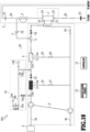
- Fig. 10 shows a flow of the dialysate in the case where the back filtration based blood return process (the normal direction in delivering liquid) is carried out by using the dialysate in the dialysate filter 10.
- Valves shown in the drawing are indicated with hatching. In the case where any of the valves is closed, the relevant valve shown in the drawing is indicated with an outline.
- the on-off valve 14c, the on-off valve V3, the on-off valve V4, and the on-off valve V2 are opened in the back filtration based blood return process (the normal direction in delivering liquid).
- the air pump 14a rotates forward.
- the opening of these on-off valves and the rotation of the air pump 14a are controlled by instructions of the controller 12.
- the controller 12 controls the number of rotations of the air pump 14a per unit time (controls the flow rate of the air from the air introducer 14) in such a way as to generate the flow of the dialysate to the dialysate circuit 3 (the dialysate introduction circuit 3a) and the blood circuit 2.
- the air pump 14a By driving the air pump 14a and opening the on-off valve 14c, the air is introduced into the dialysate filter 10 and the primary chamber 10a of the dialysate filter 10 is set to the positive pressure. Accordingly, the dialysate in the primary chamber 10a reaches the secondary chamber 10b and flows in the dialysate introduction circuit 3a. In other words, the controller 12 controls the dialysate circuit 3 and the blood circuit 2 such that the dialysate flows in the flow route shown in Fig. 10 .
- the dialysate By opening the on-off valve V3, the on-off valve V4, and the on-off valve V2, the dialysate passes through the dialysate introduction circuit 3a, the blood purifier 1 (the blood purification membrane), and the blood return side circuit 2b.
- this flow of the dialysate is indicated with an arrow of a thick chain line.
- the dialysate flows inside the blood purifier 1 in the order of the dialysate flow route, the blood purification membrane, and the blood flow route.
- the dialysate pushes out the blood remaining in the blood purifier 1 and the blood circuit 2 (the blood return side circuit 2b), and the blood is returned to the body.
- the back filtration based blood return process (the normal direction in delivering liquid) described with reference to Fig. 10 is carried out by operating at least the controller 12, the on-off valve 14c, the on-off valve V3, the on-off valve V4, the on-off valve V2, and the air pump 14a only by the power supply from the backup power source 13.
- the constituents such as the blood pump 5 and the dual pump 9 for feeding the dialysate to the dialysate circuit 3 and feeding the blood to the blood circuit 2 in the dialysis treatment may be stopped.
- Fig. 11 shows a flow of the dialysate in the case where the back filtration based blood return process (the normal direction in delivering liquid) is carried out by using the dialysate in the dialysate filter 11.
- the on-off valve 14c is closed in the case where the supply source of the dialysate is switched from the dialysate filter 10 to the dialysate filter 11. Meanwhile, the on-off valve 14d is opened.
- the opening and closing of these on-off valves are controlled by instructions of the controller 12.
- the controller 12 controls the number of rotations of the air pump 14a per unit time (controls the flow rate of the air from the air introducer 14) in such a way as to generate the flow of the dialysate to the dialysate circuit 3 (the dialysate introduction circuit 3a) and the blood circuit 2.
- the air pump 14a and opening the on-off valve 14d By driving the air pump 14a and opening the on-off valve 14d, the air is introduced into the dialysate filter 11 and the primary chamber 11a of the dialysate filter 11 is set to the positive pressure. Accordingly, the dialysate in the primary chamber 11a reaches the secondary chamber 11b and flows in the dialysate introduction circuit 3a. Thereafter, the dialysate flows in the same flow route as the flow route shown in Fig. 11 . In other words, the controller 12 controls the dialysate circuit 3 and the blood circuit 2 such that the dialysate flows in the flow route shown in Fig. 11 . In Fig. 11 , this flow of the dialysate is indicated with an arrow of a thick chain line.
- the back filtration based blood return process (the normal direction in delivering liquid) described with reference to Fig. 11 is carried out by operating at least the controller 12, the on-off valve 14d, the on-off valve V3, the on-off valve V4, the on-off valve V2, and the air pump 14a only by the power supply from the backup power source 13.
- the blood pump 5, the dual pump 9, and the like may be stopped.
- the supply source of the dialysate is switched by using the single air introducer 14.
- the configuration according to the third embodiment does not have to drive the blood pump 5 either.
- no pressure is generated in the blood circuit 2 for drawing out the dialysate, and the blood circuit 2 is hence not set to the negative pressure either. Therefore, according to the configuration of the third embodiment, it is possible to carry out the blood return more favorably as compared to the related art even in the case where the dialysate supplier 6 stops the generation and the supply of the dialysate.
- the above-described first to third embodiments use the two dialysate filters (the dialysate filter 10 and the dialysate filter 11), a single dialysate filter or three or more dialysate filters may be used instead.
- the blood remaining in the blood purifier 1 and the blood circuit 2 is returned to the body by using the dialysate in n pieces (n is an integer equal to or larger than 1) of dialysate filters.
- the supply source of the dialysate is switched in three steps in accordance with the above-described determination method. While the blood return is carried out by using the dialysate stored in the dialysate filter 10 and the dialysate filter 11, a dedicated chamber for storing the dialysate may be provided instead.
- the primary air introducer 7 may be configured to include a compressed air tank encapsulating compressed air instead of including the air pump 7a.
- the air is introduced from the compressed air tank to the dialysate filter 10 through the air introduction route 7b by opening the on-off valve 7c.
- the secondary air introducer 8 and the air introducer 14 may also be configured to include compressed air tanks instead of including the air pump 8a and the air pump 14a.
- the rotations of the air pump 7a, the air pump 8a, the air pump 14a, and the blood pump 5 are controlled by using the rotary encoders.
- the rotations may be controlled by using other modes instead.
- the rotations of the air pump 7a, the air pump 8a, the air pump 14a, and the blood pump 5 may be carried out based on open loop control using a pulse motor.
- the back filtration based blood return processes (the normal direction in delivering liquid and the reverse direction in delivering liquid) and the rehydration based blood return processes (the normal direction in delivering liquid and the reverse direction in delivering liquid) may be combined as desired.
- the rehydration based blood return process (the normal direction in delivering liquid) may be carried out in the first place by using the dialysate in the dialysate filter 10
- the back filtration based blood return process (the reverse direction in delivering liquid) may be carried out by using the dialysate in the dialysate filter 11 in the case of switching the supply source of the dialysate.
- the above-described first to third embodiments are mainly applied to the blood return processes.
- the present disclosure is not limited only to these examples.
- the above-described processing may also be applied to a fluid replacement process for preventing a blood pressure drop caused by reduction in blood of the patient due to a water removal process to remove extra water from the blood, and the like.
- the dialysate is injected to the blood circuit so as to supplement the blood in the body.
- the blood purification apparatus is implemented by a computer program to be executed by the controller 12.
- the computer program may be stored in a non-transitory storage medium.
- the non-transitory storage medium include a read only memory (ROM), a random access memory (RAM), a register, a cache memory, a semiconductor memory device, a magnetic medium such as a built-in hard disk drive and a removable disk drive, a magneto-optical medium, an optical medium such as a CD-ROM disc and a digital versatile disc (DVD), and so forth.
Landscapes
- Health & Medical Sciences (AREA)
- Heart & Thoracic Surgery (AREA)
- Vascular Medicine (AREA)
- Hematology (AREA)
- Engineering & Computer Science (AREA)
- Anesthesiology (AREA)
- Biomedical Technology (AREA)
- Life Sciences & Earth Sciences (AREA)
- Animal Behavior & Ethology (AREA)
- General Health & Medical Sciences (AREA)
- Public Health (AREA)
- Veterinary Medicine (AREA)
- Cardiology (AREA)
- Urology & Nephrology (AREA)
- Emergency Medicine (AREA)
- External Artificial Organs (AREA)
Abstract
Description
- The present disclosure relates to a blood purification apparatus, or more specifically, to a blood purification apparatus that returns blood remaining in a blood circuit to a body by using a dialysate in a dialysate filter.
- In a case where kidneys that constitute part of organs of a human do not operate normally (a renal failure), functions to produce urine out of extra water in the body, to excrete unwanted waste products in the body, and so forth do not work well. To deal with the renal failure, a blood purification apparatus (a dialysis apparatus) is used for conducting a therapy (a dialysis treatment) to extracorporeally circulate blood from a patient and to filter waste products and water in the blood by using a blood purifier.
- The blood purification apparatus withdraws blood from a patient and introduces the blood into the blood purifier (a blood flow route) through a blood circuit while introducing a dialysate from a supply source of the dialysate (a dialysate supplier) into the blood purifier (a dialysate flow route) through a dialysate circuit at the same time. The blood purification apparatus purifies the blood by exchanging components such as waste products and electrolytes between the blood and the dialysate through the blood purifier, and returns the purified blood to the body. Since the blood remains in the blood circuit after the introduction of the blood into the blood circuit in the dialysis treatment, an operation to return the remaining blood to the body (blood return) is generally carried out by feeding normal saline into the blood circuit. The dialysate may also be used as a substitute liquid for this normal saline.
- PTL 1:
Japanese Patent No. 5693890 - PTL 1 discloses a blood purification apparatus configured to return blood in a blood circuit to a body by supplying a dialysate in a filter to the blood circuit. The blood purification apparatus described in PTL 1 introduces air into the filter through an air introduction line, and draws the dialysate in the filter into the blood circuit by rotating a blood pump that is operated by a backup battery. This configuration enables blood return even in a case where power supply to the blood purification apparatus is stopped.
- The blood purification apparatus described in PTL 1 releases the air at a tip of the air introduction line and rotates the blood pump in order to draw out the dialysate in the blood circuit. Accordingly, a circuit portion at an entrance side of the blood pump is prone to be set to a negative pressure due to a pressure generated by rotation of the blood pump. This is not desirable in light of conducting the blood return.
- The present invention provides a blood purification apparatus that returns blood to a patient while preventing or relaxing a negative pressure inside a blood circuit.
- A blood purification apparatus of an embodiment includes: a blood circuit and a dialysate circuit coupled to each other through a blood purifier; an air introduction route coupled to the dialysate circuit; an air introducer provided to any of the dialysate circuit and the air introduction route and configured to set the dialysate circuit to a positive pressure by introducing air into the dialysate circuit through the air introduction route; and a controller configured to control the air introducer in such a way as to feed a dialysate from the dialysate circuit to the blood circuit, and to control the blood circuit and the dialysate circuit in such a way as to return blood in the blood circuit and the blood purifier to a body by feeding the dialysate from the dialysate circuit to the blood circuit.
- A method to be executed by a blood purification apparatus of another embodiment is a method to be executed by a blood purification apparatus provided with a blood circuit and a dialysate circuit coupled to each other through a blood purifier, an air introduction route coupled to the dialysate circuit, an air introducer provided to any of the dialysate circuit and the air introduction route and configured to set the dialysate circuit to a positive pressure by introducing air into the dialysate circuit through the air introduction route, and a controller, the method comprising the steps of: causing the controller to control the air introducer in such a way as to feed a dialysate from the dialysate circuit to the blood circuit; and causing the controller to control the blood circuit and the dialysate circuit in such a way as to return blood in the blood circuit and the blood purifier to a body by feeding the dialysate from the dialysate circuit to the blood circuit.
- According to the blood purification apparatus of the embodiment, it is possible to prevent the blood circuit from being set to a negative pressure or relaxing a state of the negative pressure.
-
- [
Fig. 1] Fig. 1 is an overall configuration diagram of a blood purification apparatus according to a first embodiment; - [
Fig. 2] Fig. 2 is a diagram showing relations among air introducers and chambers in a blood circuit; - [
Fig. 3] Fig. 3 is a diagram showing a flow of a dialysate in a back filtration based blood return process (a normal direction in delivering liquid) by using the dialysate in a (primary) dialysate filter; - [
Fig. 4] Fig. 4 is a diagram showing a flow of the dialysate in the back filtration based blood return process (the normal direction in delivering liquid) by using the dialysate in a (secondary) dialysate filter; - [
Fig. 5] Fig. 5 is a diagram showing a flow of the dialysate in the back filtration based blood return process (a reverse direction in delivering liquid) by using the dialysate in the (primary) dialysate filter; - [
Fig. 6] Fig. 6 is an overall configuration diagram of a blood purification apparatus according to a second embodiment; - [
Fig. 7] Fig. 7 is a diagram showing a flow of the dialysate in a rehydration based blood return process (the normal direction in delivering liquid) by using the dialysate in the (primary) dialysate filter; - [
Fig. 8] Fig. 8 is a diagram showing a flow of the dialysate in the rehydration based blood return process (the reverse direction in delivering liquid) by using the dialysate in the (primary) dialysate filter; - [
Fig. 9] Fig. 9 is an overall configuration diagram of a blood purification apparatus according to a third embodiment; - [
Fig. 10] Fig. 10 is a diagram showing a flow of the dialysate in the back filtration based blood return process (the normal direction in delivering liquid) by using the dialysate in the (primary) dialysate filter; and - [
Fig. 11] Fig. 11 is a diagram showing a flow of the dialysate in the back filtration based blood return process (the normal direction in delivering liquid) by using the dialysate in the (primary) dialysate filter. - Blood purification apparatuses (dialysis apparatuses) according to embodiments will be described below with reference to the accompanying drawings. A blood purification apparatus according to each embodiment returns blood that remains in a blood circuit to a body (blood return) by using a dialysate in a dialysate filter in a case where power supply from a main power source to the blood purification apparatus is stopped due to blackout and the like, for example. In order to carry out this blood return, some constituents of the blood purification apparatus are operated by power supply from a backup power source.
-
Fig. 1 is a block diagram showing a configuration of ablood purification apparatus 100 according to a first embodiment. Theblood purification apparatus 100 includes a blood purifier 1, a blood circuit 2, adialysate circuit 3, a rehydration circuit 4, a blood pump 5, a dialysate supplier 6, a primary air introducer 7, a secondary air introducer 8, a dual pump 9, adialysate filter 10, adialysate filter 11, acontroller 12, and abackup power source 13 as main constituents. The constituents shown inFig. 1 merely represent examples of constituents for implementing the present embodiment, and a chamber for trapping bubbles of the blood flowing in the blood circuit 2, a water removal line and a water removal pump for removing water from the blood of a patient, and the like are also provided in reality. - The blood purifier 1, which is also referred to as a dialyzer, purifies blood of a patient. The blood purifier 1 includes a blood introduction inlet 1a that introduces the blood from the blood circuit 2, and a
blood introduction outlet 1b that discharges the purified blood. Moreover, the blood purifier 1 includes adialysate introduction inlet 1c that introduces a dialysate from thedialysate circuit 3, and adialysate drainage outlet 1d that drains the dialysate (drainage). Furthermore, the blood purifier 1 includes a blood purification membrane that is provided inside. The blood purification membrane is formed from a bundle of hollow fibers having pores on side surfaces (a hollow fiber membrane). An inner side of the blood purification membrane is a blood flow route (not shown) and an outer side of the blood purification membrane (the hollow fibers) is a dialysate flow route (not shown). - The blood to flow in the blood purifier 1 flows in the blood flow route and unwanted substances such as uremic substances are removed by passing through the pores in the blood purification membrane by one or both of diffusion and ultrafiltration. The dialysate to flow in the blood purifier 1 flows in the dialysate flow route and the blood is supplemented only with substances such as electrolytes included in the dialysate, which are necessary for a human body. Here, the inner side of the blood purification membrane can also function as the dialysate flow route and the outer side of the blood purification membrane can also function as the blood flow route.
- The blood circuit 2 and the
dialysate circuit 3 are coupled to each other through the blood purification membrane of the blood purifier 1, and are configured to bidirectionally circulate the blood and the dialysate. The blood circuit 2 is a flow route that introduces the blood removed from the patient into the blood purifier 1 and returns the blood discharged from the blood purifier 1 (the purified blood) to the body (the blood flows in a direction indicated with an arrow A inFig. 1 ) at the time of a dialysis treatment. The blood circuit 2 is mainly formed from a tube that enables passage of the blood. The blood circuit 2 includes a bloodremoval side circuit 2a and a bloodreturn side circuit 2b. - The blood
removal side circuit 2a is a flow route that introduces the blood removed from the patient into the blood purifier 1. One end of the bloodremoval side circuit 2a is attached to a blood removal side puncture needle (not shown) that is punctured into a blood vessel of the patient, and another end thereof is joined to the blood introduction inlet 1a. An on-off valve (a solenoid valve) V1 is provided to the bloodremoval side circuit 2a. A flow of the blood in the bloodremoval side circuit 2a is controlled by opening and closing the on-off valve V1. The bloodreturn side circuit 2b is a flow route that returns the blood discharged from the blood purifier 1 to the body. One end of the bloodreturn side circuit 2b is attached to a blood return side puncture needle (not shown) that is punctured into a blood vessel of the patient, and another end thereof is joined to theblood introduction outlet 1b. An on-off valve (a solenoid valve) V2 is provided to the bloodreturn side circuit 2b. A flow of the blood in the blood return side circuit is controlled by opening and closing the on-off valve V2. - The blood pump 5 is provided to the blood
removal side circuit 2a and configured to deliver a liquid in the blood circuit 2 in a direction of movement from the bloodremoval side circuit 2a to the bloodreturn side circuit 2b (hereinafter referred to as a normal direction in delivering liquid) or in a direction of movement from the bloodreturn side circuit 2b to the bloodremoval side circuit 2a (hereinafter referred to as a reverse direction in delivering liquid). The blood pump 5 is formed from a peristaltic pump that includes a stator and a rotor, and the peristaltic pump is driven in such a way as to rotate the rotor. The rotor is rotated by an actuator (not shown) such as an electric motor under control of thecontroller 12. The blood pump 5 is provided with a rotary encoder (not shown). The rotary encoder detects the number of rotations of the rotor. By forward rotation of the blood pump 5, the bloodremoval side circuit 2a pinched between the stator and the rotor is squeezed so as to generate the flow in the normal direction in delivering liquid. Meanwhile, by reverse rotation of the blood pump 5, the bloodremoval side circuit 2a is squeezed so as to generate the flow in the reverse direction in delivering liquid. - The
dialysate circuit 3 is a flow route that supplies the dialysate to the blood purifier 1 and/or the blood circuit 2, and discharges the drainage of the dialysate from the blood purifier 1. Thedialysate circuit 3 is mainly formed from a tube that enables passage of the dialysate. Thedialysate circuit 3 includes adialysate introduction circuit 3a, adialysate drainage circuit 3b, adialysate bypass circuit 3c, and adialysate bypass circuit 3d. - The
dialysate introduction circuit 3a is a flow route from the dialysate supplier 6 to thedialysate introduction inlet 1c. The dialysate flows in the blood purifier 1 by way of thedialysate introduction circuit 3a. An on-off valve (a solenoid valve) V3, an on-off valve (a solenoid valve) V4, and a dialysate port P are provided to thedialysate introduction circuit 3a. A flow of the dialysate into the blood purifier 1 is controlled by opening and closing the on-off valve V3 and the on-off valve V4. The dialysate port P takes out the dialysate. - The
dialysate drainage circuit 3b is a flow route from thedialysate drainage outlet 1d to a dialysate drainer (not shown). The drainage from the blood purifier 1 is drained to the dialysate drainer by way of thedialysate drainage circuit 3b. An on-off valve (a solenoid valve) V6 is provided to thedialysate drainage circuit 3b. A flow of the drainage to the dialysate drainer is controlled by opening and closing the on-off valve V6. - Each of the
dialysate bypass circuit 3c and thedialysate bypass circuit 3d is a flow route from thedialysate introduction circuit 3a to thedialysate drainage circuit 3b. An on-off valve (a solenoid valve) V7 is provided to thedialysate bypass circuit 3c. Likewise, an on-off valve (a solenoid valve) V8 is provided to thedialysate bypass circuit 3d. A flow of the dialysate from thedialysate introduction circuit 3a to thedialysate drainage circuit 3b is controlled by opening and closing the on-off valves V7 and V8. - The
dialysate bypass circuit 3c and thedialysate bypass circuit 3d are the flow routes for preventing the inappropriate dialysate from flowing into the blood circuit 2. For example, theblood purification apparatus 100 is provided with a warmer (not shown) for warming the dialysate. In the case where the temperature of the dialysate exceeds a predetermined temperature due to the warmer at the time of the dialysis treatment, the dialysate flows to thedialysate drainage circuit 3b through thedialysate bypass circuit 3c and/or thedialysate bypass circuit 3d in order to prevent the dialysate at the high temperature from flowing to the blood circuit 2. In this case, the on-off valve V7 and/or the on-off valve V8 are opened. - The rehydration circuit 4 is a connection flow route that connects the blood circuit 2 to the
dialysate circuit 3 while bypassing the blood purifier 1. Specifically, the rehydration circuit 4 is a flow route from the dialysate port P to the bloodremoval side circuit 2a for supplying the dialysate from thedialysate circuit 3 to the blood circuit 2 while bypassing the blood purifier 1. An on-off valve (a solenoid valve) V5 is provided to the rehydration circuit 4. A flow of the dialysate to the bloodremoval side circuit 2a is controlled by opening and closing the on-off valve V5. - The dialysate supplier 6 introduces the dialysate into the
dialysate introduction circuit 3a. Here, the dialysate supplier 6 receives supply of pure water from a not-illustrated pure water machine (an RO water machine) provided outside theblood purification apparatus 100, and receives supply of (suctions) an undiluted solution from a not-illustrated undiluted solution tank externally mounted on theblood purification apparatus 100. Subsequently, the dialysate supplier 6 produces the dialysate by mixing the undiluted solution of the dialysate with the pure water in a predetermined proportion, and introduces the dialysate into thedialysate introduction circuit 3a. In this embodiment, theblood purification apparatus 100 includes the dialysate supplier 6. However, without limitation to the foregoing, the dialysate supplier 6 may be externally provided as a dialysate supply apparatus, and the blood purification apparatus may receive the supply of the dialysate from the dialysate supply apparatus. - While the dialysate supplier 6 generates the dialysate and introduces the dialysate into the
dialysate introduction circuit 3a at normal times (such as at the time of the dialysis treatment), generation of the new dialysate may be restricted in the event of a blackout and the like. In this case, the supply of the dialysate from the dialysate supplier 6 to thedialysate circuit 3 is stopped and the dialysate stored in thedialysate filter 10 and/or thedialysate filter 11 is introduced into thedialysate circuit 3 instead. Details will be described later. - The
primary air introducer 7 introduces the air into the (primary)dialysate filter 10 to be described later. The air is introduced into thedialysate filter 10 by theprimary air introducer 7. In the case where the air is introduced into thedialysate filter 10, thedialysate filter 10 is set to a positive pressure and the dialysate stored in thedialysate filter 10 flows to the dialysate circuit 3 (the dialysate port P). In other words, theprimary air introducer 7 plays roles in pushing the dialysate stored in thedialysate filter 10 out to thedialysate circuit 3, and feeding the dialysate to the dialysate circuit 3 (thedialysate introduction circuit 3a) and the blood circuit 2. - The
primary air introducer 7 includes anair pump 7a, anair introduction route 7b, an on-off valve (a solenoid valve) 7c, anair filter 7d, and anair filter 7e. Theair pump 7a incorporates a rotor and drives the rotor so as to perform rotation. The rotor is rotated by an actuator (not shown) such as an electric motor under control of thecontroller 12. Theair pump 7a is provided with a rotary encoder (not shown). The rotary encoder detects the number of rotations of the rotor. By the rotation of theair pump 7a, the air is introduced into thedialysate filter 10 through theair introduction route 7b. - The air introduced into the
dialysate filter 10 by the drive of theair pump 7a generates a flow of the dialysate to the dialysate circuit 3 (thedialysate introduction circuit 3a) and the blood circuit 2. The flow of the air to thedialysate filter 10 is controlled by opening and closing the on-off valve 7c provided between theair pump 7a and thedialysate filter 10. Theair filter 7d and theair filter 7e remove dust in the air. - The
secondary air introducer 8 introduces the air into the (secondary)dialysate filter 11 to be described later. The air is introduced into thedialysate filter 11 by thesecondary air introducer 8. In the case where the air is introduced into thedialysate filter 11, thedialysate filter 11 is set to a positive pressure and the dialysate stored in thedialysate filter 11 flows to the dialysate circuit 3 (the dialysate port P). In other words, thesecondary air introducer 8 plays roles in pushing the dialysate stored in thedialysate filter 11 out to thedialysate circuit 3, and in feeding the dialysate to the dialysate circuit 3 (thedialysate introduction circuit 3a) and the blood circuit 2. - The
secondary air introducer 8 includes anair pump 8a, anair introduction route 8b, an on-off valve (a solenoid valve) 8c, anair filter 8d, and anair filter 8e. Theair pump 8a incorporates a rotor and drives the rotor so as to perform rotation. The rotor is rotated by an actuator (not shown) such as an electric motor under control of thecontroller 12. Theair pump 8a is provided with a rotary encoder (not shown). The rotary encoder detects the number of rotations of the rotor. By the rotation of theair pump 8a, the air is introduced into thedialysate filter 11 through theair introduction route 8b. - The air introduced into the
dialysate filter 11 by the drive of theair pump 8a generates a flow of the dialysate to the dialysate circuit 3 (thedialysate introduction circuit 3a) and the blood circuit 2. The flow of the air to thedialysate filter 11 is controlled by opening and closing the on-off valve 8c provided between theair pump 8a and thedialysate filter 11. Theair filter 8d and theair filter 8e remove dust in the air. - One or both of the primary air introducer 7 (the
air pump 7a) and the secondary air introducer 8 (theair pump 8a) play a role in adjusting liquid levels of the liquid in chambers provided to the blood circuit 2 at the time of the dialysis treatment, for example. This liquid level adjustment will be described later. - Note that the on-off valve 7c, the
air filter 7d, and theair filter 7e are not essential structures in theprimary air introducer 7. Likewise, the on-off valve 8c, theair filter 8d, and theair filter 8e are not essential structures in thesecondary air introducer 8. - The dual pump 9 is provided across the
dialysate introduction circuit 3a and thedialysate drainage circuit 3b. The dual pump 9 introduces the dialysate to a downstream side in a liquid delivery direction of thedialysate introduction circuit 3a, and meanwhile, discharges the drainage of the dialysate to a downstream side in the liquid delivery direction of thedialysate drainage circuit 3b. In other words, the dual pump 9 plays roles as a dialysate supply pump for supplying the dialysate to the blood circuit 2 and as a dialysate drainage pump for draining the dialysate from the dialysate drainer. Here, a plunger (not shown) is provided inside a housing of the dual pump 9. A volume on thedialysate introduction circuit 3a side and a volume on thedialysate drainage circuit 3b side are defined while interposing the plunger in between, and the introduction of the dialysate and the discharge of the drainage are interlocked with reciprocation of the plunger. - The
dialysate filter 10 purifies the dialysate by trapping substances such as endotoxins contained in the dialysate supplied from the dialysate supplier 6. Thedialysate filter 10 is provided to thedialysate circuit 3, and includes aprimary chamber 10a and asecondary chamber 10b. Meanwhile, a dialysate purification membrane is provided inside thedialysate filter 10. The dialysate purification membrane is formed from a bundle of hollow fibers (a hollow fiber membrane) with side walls provided with pores. Thedialysate filter 10 is configured such that the dialysate flows from theprimary chamber 10a (an inner side of the dialysate purification membrane) to thesecondary chamber 10b (an outer side of the dialysate purification membrane). Thedialysate filter 10 has a property of blocking passage of the air with surface tension of water molecules by passing water thereto. - The
primary chamber 10a and thesecondary chamber 10b can store the dialysate supplied from the dialysate supplier 6. In other words, at the time of the dialysis treatment, the dialysate to be purified is stored in theprimary chamber 10a while the purified dialysate is stored in thesecondary chamber 10b. The stored dialysate is supplied to thedialysate circuit 3 by theprimary air introducer 7 as described later. Here, theprimary chamber 10a may be located on the outer side of the dialysate purification membrane and thesecondary chamber 10b may be located on the inner side of the dialysate purification membrane. - The
dialysate filter 11 purifies the dialysate by trapping the substances such as endotoxins contained in the dialysate supplied from the dialysate supplier 6. Thedialysate filter 11 is provided to thedialysate circuit 3, and includes aprimary chamber 11a and asecondary chamber 11b. Meanwhile, a dialysate purification membrane is provided inside thedialysate filter 11. The dialysate purification membrane is formed from a bundle of hollow fibers (a hollow fiber membrane) with side walls provided with pores. Thedialysate filter 11 is configured such that the dialysate flows from theprimary chamber 11a (an inner side of the dialysate purification membrane) to thesecondary chamber 11b (an outer side of the dialysate purification membrane). Thedialysate filter 11 has a property of blocking passage of the air with surface tension of water molecules by passing water thereto. - The
primary chamber 11a and thesecondary chamber 11b can store the dialysate supplied from the dialysate supplier 6. In other words, at the time of the dialysis treatment, the dialysate to be purified is stored in theprimary chamber 11a while the purified dialysate is stored in thesecondary chamber 11b. The stored dialysate is supplied to thedialysate circuit 3 by thesecondary air introducer 8 as described later. Here, theprimary chamber 11a may be located on the outer side of the dialysate purification membrane and thesecondary chamber 11b may be located on the inner side of the dialysate purification membrane. - The filters such as the
dialysate filter 10 and thedialysate filter 11 are generally provided to the blood purification apparatus in order to remove impurities contained in the dialysate at the time of the dialysis treatment. In the present embodiment, the pair of thedialysate filter 10 and thedialysate filter 11 are provided to thedialysate circuit 3, so that the dialysate can be purified even in the case where one of the filters fails to function. - The
controller 12 is a processing device that controls the entireblood purification apparatus 100 including theair pump 7a and theair pump 8a mentioned above, and so forth. Thecontroller 12 includes an arithmetic device and a storage device (a storage device such as a RAM and a ROM). The arithmetic device may be implemented by a processor such as a CPU and a microcontroller, an ASIC (application specific integrated circuit), an FPGA (field programmable gate array), and the like, but its mode is not limited. - The
backup power source 13 is a power unit that supplies electric power to some of the constituents such as thecontroller 12 in the case where power supply from the main power source (not shown) to theblood purification apparatus 100 is stopped due to blackout and the like, for example. By using thebackup power source 13, as described later, thecontroller 12, theprimary air introducer 7, thesecondary air introducer 8, and the like function so that the blood remaining in the blood circuit 2 can be returned to the body. - In the above-described
blood purification apparatus 100, the dialysate from the dialysate supplier 6 is introduced into thedialysate introduction circuit 3a by operating the dual pump 9 at the time of the dialysis treatment, and the dialysate is passed from thedialysate circuit 3 to the rehydration circuit 4, thus flowing in the blood purifier 1. Next, the dialysate is passed from the blood purifier 1 to thedialysate drainage circuit 3b, and is discharged from the dialysate drainer. Meanwhile, at the time of the dialysis treatment, the blood flows in the normal direction in delivering liquid by the forward rotation of the blood pump 5. Due to the flow of the dialysate at the time of the dialysis treatment mentioned above, the purified dialysate is stored in thedialysate filter 10 and thedialysate filter 11. - Next, relations among the
primary air introducer 7, thesecondary air introducer 8, and the chambers provided to the blood circuit 2 will be described with reference toFig. 2 . As mentioned above, one or both of theprimary air introducer 7 and thesecondary air introducer 8 play the role in adjusting the liquid levels of the liquid in the chambers provided to the blood circuit 2 at the time of the dialysis treatment, for example. In other words, theair pump 7a and/or theair pump 8a also play roles as liquid level adjustment pumps (the liquid level adjustment pumps are not usually used for the blood return).Fig. 2 shows a state where theair pump 7a and theair pump 8a function as the liquid level adjustment pumps. Here, instead of causing theair pump 7a and theair pump 8a to serve as the liquid level adjustment pumps, theair pump 7a, theair pump 8a, and the liquid level adjustment pump may be provided independently of one another. - In the blood circuit 2, a blood removal side
air trap chamber 2c is provided to the bloodremoval side circuit 2a, and a blood return sideair trap chamber 2d is provided to the bloodreturn side circuit 2b. The blood removal sideair trap chamber 2c is provided mainly for the purpose of trapping the air so as not to cause the air to flow into the blood purifier 1 and to develop air lock. The blood return sideair trap chamber 2d is provided mainly for the purpose of trapping the air so as not to cause the air to flow into the body of the patient through the blood circuit 2. It is not always necessary to provide both of the blood removal sideair trap chamber 2c and the blood return sideair trap chamber 2d, and only one of them may be provided. In other words, the blood removal sideair trap chamber 2c and the blood return sideair trap chamber 2d play roles as chambers to contain the blood in the blood circuit 2. - The blood removal side
air trap chamber 2c is coupled to thesecondary air introducer 8 and an on-off valve (a solenoid valve) V9 is provided therebetween. The flow of the air from thesecondary air introducer 8 to the blood removal sideair trap chamber 2c is controlled by opening and closing the on-off valve V9 (thesecondary air introducer 8 causes the air to flow to the blood removal sideair trap chamber 2c). The blood return sideair trap chamber 2d is coupled to theprimary air introducer 7 and an on-off valve (a solenoid valve) V10 is provided therebetween. The flow of the air from theprimary air introducer 7 to the blood return sideair trap chamber 2d is controlled by opening and closing the on-off valve V10 (theprimary air introducer 7 causes the air to flow to the blood return sideair trap chamber 2d). - Each of the blood removal side
air trap chamber 2c and the blood return sideair trap chamber 2d includes two layers, namely, a blood layer and an air layer. The liquid level moves down as the air is accumulated in the chamber, which may lead to the occurrence of the air lock in which the air enters the hollow fibers in the blood purifier 1. In the example shown inFig. 2 , the primary air introducer 7 (theair pump 7a) rotates forward so as to introduce the air into the blood return sideair trap chamber 2d and to move down the liquid level, or rotates in reverse so as to discharge the air from the blood return sideair trap chamber 2d and to move up the liquid level. Likewise, the secondary air introducer 8 (theair pump 8a) rotates forward so as to introduce the air into the blood removal sideair trap chamber 2c and to move down the liquid level, or rotates in reverse so as to discharge the air from the blood removal sideair trap chamber 2c and to move up the liquid level. -
Fig. 2 shows the example in which the blood removal sideair trap chamber 2c is coupled to thesecondary air introducer 8 and the blood return sideair trap chamber 2d is coupled to theprimary air introducer 7. However, this mode of connection is merely an example. For instance, the blood removal sideair trap chamber 2c may be coupled to theprimary air introducer 7 and the blood return sideair trap chamber 2d may be coupled to thesecondary air introducer 8. Alternatively, both of the blood removal sideair trap chamber 2c and the blood return sideair trap chamber 2d may be coupled to either theprimary air introducer 7 or thesecondary air introducer 8. - Next, processing according to the first embodiment will be described with reference to
Figs. 3 to 5 . In the first embodiment, a description will be given of an example of returning the blood remaining in the blood purifier 1 and the blood circuit 2 to the body by using the dialysate in thedialysate filter 10 and the dialysate filter 11 (by sequentially introducing the air into thedialysate filter 10 and the dialysate filter 11) in the case where the power supply from the main power source to theblood purification apparatus 100 is stopped due to the blackout and the like, for instance. In the case where the power supply from the main power source to theblood purification apparatus 100 is stopped, only some of the constituents in theblood purification apparatus 100 to be described later function by the power supply from thebackup power source 13. However, the dialysate supplier 6 stops the generation and supply of the dialysate. In this instance, theair pump 7a plays a role in feeding the dialysate in thedialysate filter 10 to the blood circuit 2 instead of adjusting the liquid level in the blood return sideair trap chamber 2d. Likewise, theair pump 8a plays a role in feeding the dialysate in thedialysate filter 11 to the blood circuit 2 instead of adjusting the liquid level in the blood removal sideair trap chamber 2c. - Meanwhile, the first embodiment adopts the blood return method of returning the blood to the body by introducing the dialysate from the
dialysate circuit 3 to the blood circuit 2 through the blood purification membrane of the blood purifier 1 and causing the dialysate to push out the blood in the blood purifier 1 and the blood circuit 2. In the following, this blood return method will be referred to as a back filtration based blood return process. In the back filtration based blood return process, the dialysate flows in thedialysate circuit 3 and passes from thedialysate circuit 3 to the blood purifier 1. This flow of the dialysate causes the dialysate to pass through the dialysate flow route of the blood purifier 1, whereby the dialysate pushes out the blood through the pores in the blood purification membrane, thus returning the blood to the body. -
Fig. 3 shows a flow of the dialysate in the case where the back filtration based blood return process is carried out by using the dialysate in thedialysate filter 10. In the example shown inFig. 3 , the blood is returned to the body in the normal direction in delivering liquid in the back filtration based blood return process. In the following drawings, valves among the valves (V1 to V6, V7c, and V8c) in the drawings are indicated with hatching in the case where the valves are opened, and the valves in the drawings are indicated with outlines in the case where the valves are closed. - As shown in
Fig. 3 , the on-off valve 7c, the on-off valve V3, the on-off valve V4, and the on-off valve V2 are opened in the back filtration based blood return process (the normal direction in delivering liquid). Meanwhile, theair pump 7a rotates forward. The opening of these on-off valves and the rotation of theair pump 7a are controlled by instructions of thecontroller 12. In particular, thecontroller 12 controls the number of rotations of theair pump 7a per unit time in such a way as to generate the flow of the dialysate to the dialysate circuit 3 (thedialysate introduction circuit 3a) and the blood circuit 2. In other words, thecontroller 12 controls a flow rate of the air from theprimary air introducer 7. Although not illustrated, the on-off valve V10 shown inFig. 2 is closed. - By driving the
air pump 7a and opening the on-off valve 7c, the air is introduced into thedialysate filter 10 and theprimary chamber 10a of thedialysate filter 10 is set to the positive pressure. Accordingly, the dialysate in theprimary chamber 10a reaches thesecondary chamber 10b and flows in thedialysate introduction circuit 3a. In other words, thecontroller 12 controls thedialysate circuit 3 and the blood circuit 2 such that the dialysate flows in the flow route shown inFig. 3 . - By opening the on-off valve V3, the on-off valve V4, and the on-off valve V2, the dialysate passes through the
dialysate introduction circuit 3a, the blood purifier 1 (the blood purification membrane), and the bloodreturn side circuit 2b. InFig. 3 , this flow of the dialysate is indicated with an arrow of a thick chain line. Here, the dialysate flows inside the blood purifier 1 in the order of the dialysate flow route, the blood purification membrane, and the blood flow route. By this flow of the dialysate, the dialysate pushes out the blood remaining in the blood purifier 1 and the blood circuit 2 (the bloodreturn side circuit 2b), and the blood is returned to the body. - The back filtration based blood return process (the normal direction in delivering liquid) described with reference to
Fig. 3 is carried out by operating at least thecontroller 12, the on-off valve 7c, the on-off valve V3, the on-off valve V4, the on-off valve V2, and theair pump 7a only by the power supply from thebackup power source 13. On the other hand, the constituents such as the blood pump 5 and the dual pump 9 for feeding the dialysate to thedialysate circuit 3 and feeding the blood to the blood circuit 2 in the dialysis treatment may be stopped. - In the case where the dialysate in the
dialysate filter 10 flows, the process is switched to the back filtration based blood return process (the normal direction in delivering liquid) using the dialysate in thedialysate filter 11. Specifically, in the back filtration based blood return process (the normal direction in delivering liquid), a supply source of the dialysate is switched from thedialysate filter 10 to thedialysate filter 11. This switching is carried out by thecontroller 12, and details thereof will be described later.Fig. 4 shows a flow of the dialysate in the case of carrying out the back filtration based blood return process (the normal direction in delivering liquid) by using the dialysate in thedialysate filter 11. - As shown in
Fig. 4 , in the case where the supply source of the dialysate is switched from thedialysate filter 10 to thedialysate filter 11, the on-off valve 7c is closed and theair pump 7a stops the rotation. Meanwhile, theair pump 8a rotates forward and the on-off valve 8c is opened. The opening and closing of these on-off valves, the stop of the rotation of theair pump 7a, and the rotation of theair pump 8a are controlled by instructions of thecontroller 12. In particular, thecontroller 12 controls the number of rotations of theair pump 8a per unit time in such a way as to generate the flow of the dialysate to the dialysate circuit 3 (thedialysate introduction circuit 3a) and the blood circuit 2. In other words, thecontroller 12 controls a flow rate of the air from thesecondary air introducer 8. Although not illustrated, the on-off valve V9 shown inFig. 2 is closed. - By driving the
air pump 8a and opening the on-off valve 8c, the air is introduced into thedialysate filter 11 and the primary chamber 1 1a of thedialysate filter 11 is set to the positive pressure. Accordingly, the dialysate in theprimary chamber 11a reaches thesecondary chamber 11b and flows in thedialysate introduction circuit 3a. Thereafter, the dialysate flows in the same flow route as the flow route shown inFig. 3 . In other words, thecontroller 12 controls thedialysate circuit 3 and the blood circuit 2 such that the dialysate flows in the flow route shown inFig. 4 . InFig. 4 , this flow of the dialysate is indicated with an arrow of a thick chain line. - The back filtration based blood return process (the normal direction in delivering liquid) described with reference to
Fig. 4 is carried out by operating at least thecontroller 12, the on-off valve 8c, the on-off valve V3, the on-off valve V4, the on-off valve V2, and theair pump 8a only by the power supply from thebackup power source 13. On the other hand, the blood pump 5, the dual pump 9, and the like may be stopped. - In order to switch the supply source of the dialysate, the
controller 12 determines that the dialysate in thedialysate filter 10 is introduced into (pushed out to) thedialysate circuit 3. This determination may be carried out by detecting that theprimary chamber 10a is set to the positive pressure. In this case, a pressure gauge is provided to theprimary chamber 10a and the pressure gauge detects a pressure of the air. The detected pressure value is transmitted to thecontroller 12. Thecontroller 12 determines whether or not the pressure value exceeds a predetermined threshold. - Meanwhile, the determination may be carried out by detecting that bubbles are generated in the dialysate in the
primary chamber 10a, because in the case where the air is introduced into theprimary chamber 10a, the bubbles may be generated by the air that is mixed into the dialysate in theprimary chamber 10a. In this case, an ultrasonic sensor is provided to theprimary chamber 10a, for example, and the ultrasonic sensor detects a voltage corresponding to vibration of the dialysate. The bubbles have a higher attenuation rate than that of the dialysate. Accordingly, the generation of the bubbles can be detected by determining that the voltage value exceeds a predetermined threshold. The detected voltage value is transmitted to thecontroller 12. Thecontroller 12 determines whether or not the voltage value exceeds a predetermined threshold. - Meanwhile, the determination may be carried out by measuring a temperature of the air introduced from the
primary air introducer 7 and a temperature of a flow route (from theprimary air introducer 7 to the dialysate filter 10) of thedialysate introduction circuit 3a, and determining whether or not the temperature of thedialysate introduction circuit 3a falls within a predetermined range based on the temperature of the introduced air. Because, in a case where a predetermined amount of the air is introduced to thedialysate filter 10, the temperature of the flow route comes close to the temperature of the introduced air. In this case, a thermometer is provided at an inlet of theprimary air introducer 7, for example, and the thermometer measures the temperature of the air introduced from theprimary air introducer 7. Meanwhile, another thermometer is also provided at the flow route between theprimary air introducer 7 and thedialysate filter 10, and the thermometer detects the temperature of the flow route. Both of the detected temperature values are transmitted to thecontroller 12. Thecontroller 12 determines whether or not each temperature value falls within a predetermined range. - Moreover, the determination may be carried out by determining whether or not the dialysate that flows in the
dialysate introduction circuit 3a reaches a predetermined amount (such as a volume of the dialysate filter 10 (theprimary chamber 10a and thesecondary chamber 10b)). In this case, a flowmeter is provided to thedialysate introduction circuit 3a and the flowmeter measures a flow rate of the dialysate flowing in thedialysate introduction circuit 3a. The detected flow rate value is transmitted to thecontroller 12. Thecontroller 12 determines whether or not the flow rate value reaches a predetermined amount. - In the present embodiment, the blood return is carried out by using the dialysate in the two dialysate filters (the
dialysate filter 10 and the dialysate filter 11). For example, the supply source of the dialysate is switched from thedialysate filter 10 to thedialysate filter 11 in the case where it is not possible to return the blood sufficiently only with the dialysate in thedialysate filter 10. Here, the two dialysate filters (thedialysate filter 10 and the dialysate filter 11) are provided to thedialysate circuit 3 from a fail-safe point of view and are designed such that the amount of the dialysate that remains in the two dialysate filters corresponds to the amount of the blood that remains in the blood circuit 2. As a consequence, it is possible to carry out the blood return in a desired amount by introducing the air into the two dialysate filters. Here, the number of the dialysate filters is not limited only to two. For example, a single dialysate filter may be designed such that the amount of the dialysate remaining therein corresponds to the amount of the blood remaining in the blood circuit 2, and the blood return may be carried out likewise by introducing the air into the single dialysate filter only. - As described above, in the first embodiment, the back filtration based blood return process (the normal direction in delivering liquid) is carried out by using the dialysate in the
dialysate filter 10 and thedialysate filter 11. According to the blood purification apparatus described in PTL 1, the introduction of the air into the filter through the air introduction line does not bring about the flow of the dialysate to the blood circuit, and the dialysate in the filter is drawn out to the blood circuit by driving the blood pump. Therefore, the blood purification apparatus described in PTL 1 has to drive the blood pump. - Meanwhile, according to the blood purification apparatus described in PTL 1, a portion of the circuit on the inlet side of the blood pump may be set to a negative pressure due to a pressure generated by the rotation of the blood pump for drawing out the dialysate in the blood circuit. The negative pressure in the blood circuit may cause burst of blood cell components (hemolysis) of the blood located inside and/or deterioration in ejection accuracy of the blood pump.
- In the configuration of the first embodiment, the dialysate in the
dialysate filter 10 flows to thedialysate circuit 3 and the blood circuit 2 by driving theair pump 7a. It is therefore not necessary to drive the blood pump 5 in order to draw out the dialysate. Moreover, in the configuration of the first embodiment, no pressure is generated in the blood circuit 2 for drawing out the dialysate, and the blood circuit 2 is hence not set to the negative pressure. The same applies to the case of using the dialysate in thedialysate filter 11. Therefore, according to the configuration of the first embodiment, it is possible to carry out the blood return more favorably as compared to the related art even in the case where the dialysate supplier 6 stops the generation and the supply of the dialysate. - Moreover, only the
controller 12, the on-off valve 7c, the on-off valve V3, the on-off valve V4, the on-off valve V2, and theair pump 7a are operated in the configuration according to the first embodiment. From this perspective, it is possible to carry out the blood return by the power supply from thebackup power source 13 to the minimum required constituents particularly in the case where the power supply from the main power source to theblood purification apparatus 100 is stopped. - Here, the blood pump 5 may be driven by also supplying the power from the
backup power source 13 to the blood pump 5. In this case, the flows of the blood and the dialysate in the normal direction in delivering liquid are generated in the blood circuit 2. Accordingly, the blood pump 5 rotates forward. In other words, a pressure for drawing out the dialysate is generated in the blood circuit 2. In order not to set the blood circuit 2 to the negative pressure, the pressure in thedialysate circuit 3 caused by the introduction of the air into the dialysate filter 10 (or the dialysate filter 11) is controlled not to exceed a predetermined threshold. This threshold may be an experimentally obtained value for keeping the blood circuit 2 from being set to the negative pressure (or keeping the blood in the blood circuit 2 from being hemolyzed). Instead, the pressure in thedialysate circuit 3 generated by the introduction of the air into the dialysate filter 10 (or the dialysate filter 11) may be controlled such that the pressure becomes higher than a pressure in the blood circuit 2 generated by driving the blood pump 5. - The above-mentioned control may be carried out by performing control so as to rotate the
air pump 7a and the blood pump 5 at predetermined numbers of rotations per unit time (to rotate theair pump 7a at a higher number of rotations per unit time than that of the blood pump 5, for example) such that the pressure in thedialysate circuit 3 does not exceed the threshold (or becomes higher than the pressure in the blood circuit 2), for example. The predetermined numbers of rotations may be experimentally obtained values. In this case, the encoders detect the number of rotations of theair pump 7a and the number of rotations of the blood pump 5. The detected numbers of rotations are transmitted to thecontroller 12. Based on the detected numbers of rotations, thecontroller 12 controls theair pump 7a and the blood pump 5 in such a way as to rotate the pumps at the predetermined numbers of rotations. - Likewise, the above-mentioned control may be carried out by performing control so as to rotate the
air pump 8a and the blood pump 5 at predetermined numbers of rotations per unit time (to rotate theair pump 8a at a higher number of rotations per unit time than that of the blood pump 5, for example) such that the pressure in thedialysate circuit 3 does not exceed the threshold (or becomes higher than the pressure in the blood circuit 2), for example. In this case, the encoders detect the number of rotations of theair pump 8a and the number of rotations of the blood pump 5. The detected numbers of rotations are transmitted to thecontroller 12. Based on the detected numbers of rotations, thecontroller 12 controls theair pump 8a and the blood pump 5 in such a way as to rotate the pumps at the predetermined numbers of rotations. - Alternatively, the above-mentioned control may be carried out by controlling the number of rotations of the
air pump 7a per unit time (or the number of rotations of theair pump 8a per unit time) and the number of rotations of the blood pump 5 per unit time based on the pressure in thedialysate circuit 3 and the pressure in the blood circuit 2. In this case, a pressure gauge is provided to thedialysate circuit 3 and the pressure gauge detects a pressure in thedialysate circuit 3. Meanwhile, another pressure gauge is provided to the blood circuit 2 and the pressure gauge detects a pressure in the blood circuit 2. The detected pressure values are transmitted to thecontroller 12, respectively. Based on the detected pressure values, thecontroller 12 controls both of them so as to increase the number of rotations of theair pump 7a per unit time (or the number of rotations of theair pump 8a per unit time), and/or to decrease the number of rotations of the blood pump 5 per unit time. - In the back filtration based blood return process, a back filtration based blood return process (the reverse direction in delivering liquid) to return the blood to the body in the reverse direction in delivering liquid may be carried out instead of or in addition to the blood return process described with reference to
Figs. 3 and4 .Fig. 5 shows a flow of the dialysate in the case of carrying out the back filtration based blood return process (the reverse direction in delivering liquid) by using the dialysate in thedialysate filter 10. - As shown in
Fig. 5 , the on-off valve 7c, the on-off valve V3, the on-off valve V4, and the on-off valve V1 are opened in the back filtration based blood return process (the reverse direction in delivering liquid). Meanwhile, theair pump 7a rotates forward. Moreover, the blood pump 5 rotates in reverse. The opening of these on-off valves, the rotation of theair pump 7a, and the rotation of the blood pump 5 are controlled by instructions of thecontroller 12. In particular, thecontroller 12 controls the number of rotations of theair pump 8a per unit time (controls the flow rate of the air in the secondary air introducer 8) in such a way as to generate the flow of the dialysate to the dialysate circuit 3 (thedialysate introduction circuit 3a) and the blood circuit 2. - By driving the
air pump 7a and opening the on-off valve 7c, the air is introduced into thedialysate filter 10 and theprimary chamber 10a of thedialysate filter 10 is set to the positive pressure. Accordingly, the dialysate in theprimary chamber 10a reaches thesecondary chamber 10b and flows in thedialysate introduction circuit 3a. In other words, thecontroller 12 controls thedialysate circuit 3 and the blood circuit 2 such that the dialysate flows in the flow route shown inFig. 5 . - By opening the on-off valve V3, the on-off valve V4, and the on-off valve V1, the dialysate passes through the
dialysate introduction circuit 3a, the blood purifier 1 (the blood purification membrane), and the bloodremoval side circuit 2a. InFig. 5 , this flow of the dialysate is indicated with an arrow of a thick chain line. Here, the dialysate flows inside the blood purifier 1 in the order of the dialysate flow route, the blood purification membrane, and the blood flow route. By this flow of the dialysate, the dialysate pushes out the blood remaining in the blood purifier 1 and the blood circuit 2 (the bloodremoval side circuit 2a), and the blood is returned to the body. - The back filtration based blood return process (the reverse direction in delivering liquid) described with reference to
Fig. 5 is carried out by operating at least thecontroller 12, the on-off valve 7c, the on-off valve V3, the on-off valve V4, the on-off valve V1, theair pump 7a, and the blood pump 5 only by the power supply from thebackup power source 13. On the other hand, the constituents such as the dual pump 9 for feeding the dialysate to thedialysate circuit 3 in the dialysis treatment may be stopped. - In the case where the dialysate in the
dialysate filter 10 flows, the supply source of the dialysate is switched from thedialysate filter 10 to thedialysate filter 11. The switching of the supply source of the dialysate has been described with reference toFigs. 3 and4 , and detailed explanations thereof will be omitted. In the case where the supply source of the dialysate is switched from thedialysate filter 10 to thedialysate filter 11, the back filtration based blood return process (the reverse direction in delivering liquid) is carried out by using the dialysate in thedialysate filter 11. - The blood pump 5 is driven in the back filtration based blood return process (the reverse direction in delivering liquid). Accordingly, the
air pump 7a (or theair pump 8a) and the blood pump 5 are controlled such that the pressure in thedialysate circuit 3 becomes higher than the pressure in the blood circuit 2. This control has been described with reference toFigs. 3 and4 , and detailed explanations thereof will be omitted. - Here, both of the back filtration based blood return process (the normal direction in delivering liquid) and the back filtration based blood return process (the reverse direction in delivering liquid) may be carried out. For example, the back filtration based blood return process (the normal direction in delivering liquid) may be carried out in the first place by using the dialysate in the
dialysate filter 10, and the back filtration based blood return process (the reverse direction in delivering liquid) may be carried out by using the dialysate in thedialysate filter 11 in the case of switching the supply source of the dialysate. Alternatively, the back filtration based blood return process (the reverse direction in delivering liquid) may be carried out in the first place by using the dialysate in thedialysate filter 10, and the back filtration based blood return process (the normal direction in delivering liquid) may be carried out by using the dialysate in thedialysate filter 11 in the case of switching the supply source of the dialysate. By carrying out both of the back filtration based blood return process (the normal direction in delivering liquid) and the back filtration based blood return process (the reverse direction in delivering liquid), it is possible to return the blood remaining in both of the bloodremoval side circuit 2a and the bloodreturn side circuit 2b to the body. -
Fig. 6 is a block diagram showing a configuration of ablood purification apparatus 200 according to a second embodiment. As compared to theblood purification apparatus 100 according to the first embodiment, theblood purification apparatus 200 has a different configuration of the rehydration circuit 4 and the configurations of the rest are the same. The rehydration circuit 4 of theblood purification apparatus 100 is the flow route from the dialysate port P to the bloodremoval side circuit 2a. Meanwhile, the rehydration circuit 4 of theblood purification apparatus 200 includes a blood removalside rehydration circuit 4a and a blood returnside rehydration circuit 4b. The blood removalside rehydration circuit 4a corresponds to the rehydration circuit 4 of theblood purification apparatus 100. - The blood return
side rehydration circuit 4b is a flow route from the dialysate port P to the bloodreturn side circuit 2b for returning the blood in the blood circuit 2 to the body by a rehydration based blood return process (the reverse direction in delivering liquid) to be described later. An on-off valve (a solenoid valve) V11 is provided to the blood returnside rehydration circuit 4b. The flow of the dialysate to the bloodreturn side circuit 2b is controlled by opening and closing the on-off valve V11. - Next, processing according to the second embodiment will be described with reference to
Figs. 7 and8 . In the second embodiment, a description will be given only of an example of returning the blood remaining in the blood purifier 1 and the blood circuit 2 to the body by using the dialysate in thedialysate filter 10. However, the dialysate in thedialysate filter 11 may also be used in the second embodiment as with the first embodiment. Specifically, in the case where the dialysate in thedialysate filter 10 flows, the supply source of the dialysate is switched from thedialysate filter 10 to thedialysate filter 11. Only some of the constituents to be described later function by the power supply from thebackup power source 13 in theblood purification apparatus 200 as well. - The second embodiment adopts the blood return method of returning the blood to the body by introducing the dialysate to the blood circuit 2 through the rehydration circuit 4 and causing the dialysate to push out the blood in the blood circuit 2. In the following, this blood return method will be referred to as the rehydration based blood return process. In the rehydration based blood return process, the dialysate flows in the
dialysate circuit 3 and passes from thedialysate circuit 3 to the rehydration circuit 4 and the blood circuit 2. This flow of the dialysate causes the dialysate to flow in the blood circuit of the blood purifier 1, whereby the dialysate pushes out the blood remaining in the blood circuit 2 and the blood purifier 1, thus returning the blood to the body. -
Fig. 7 shows a flow of the dialysate in the case where the rehydration based blood return process is carried out by using the dialysate in thedialysate filter 10. In the example shown inFig. 7 , the blood is returned to the body in the normal direction in delivering liquid in the rehydration based blood return process. Valves shown in the drawing are indicated with hatching. In the case where any of the valves is closed, the relevant valve shown in the drawing is indicated with an outline. - As shown in
Fig. 7 , the on-off valve 7c, the on-off valve V3, the on-off valve V5, and the on-off valve V2 are opened in the rehydration based blood return process (the normal direction in delivering liquid). Meanwhile, theair pump 7a rotates forward. Moreover, the blood pump 5 rotates forward. The opening of these on-off valves, the rotation of theair pump 7a, and the rotation of the blood pump 5 are controlled by instructions of thecontroller 12. In particular, thecontroller 12 controls the number of rotations of theair pump 7a per unit time (controls the flow rate of the air from the primary air introducer 7) in such a way as to generate the flow of the dialysate to the dialysate circuit 3 (thedialysate introduction circuit 3a), the rehydration circuit 4, and the blood circuit 2. - By driving the
air pump 7a and opening the on-off valve 7c, the air is introduced into thedialysate filter 10 and theprimary chamber 10a of thedialysate filter 10 is set to the positive pressure. Accordingly, the dialysate in theprimary chamber 10a reaches thesecondary chamber 10b and flows in thedialysate introduction circuit 3a. In other words, thecontroller 12 controls thedialysate circuit 3, the rehydration circuit 4, and the blood circuit 2 such that the dialysate flows in the flow route shown inFig. 7 . - By opening the on-off valve V3, the on-off valve V5, and the on-off valve V2, the dialysate passes through the
dialysate introduction circuit 3a, the blood removalside rehydration circuit 4a, the bloodremoval side circuit 2a, the blood purifier 1 (the blood flow route), and the bloodreturn side circuit 2b. InFig. 7 , this flow of the dialysate is indicated with an arrow of a thick chain line. By this flow of the dialysate, the dialysate pushes out the blood remaining in the blood purifier 1 and the blood circuit 2 (the bloodreturn side circuit 2b), and the blood is returned to the body. - The rehydration based blood return process (the normal direction in delivering liquid) described with reference to
Fig. 7 is carried out by operating at least thecontroller 12, the on-off valve 7c, the on-off valve V3, the on-off valve V5, the on-off valve V2, theair pump 7a, and the blood pump 5 only by the power supply from thebackup power source 13. On the other hand, the constituents such as the dual pump 9 for feeding the dialysate to thedialysate circuit 3 and feeding the blood to the blood circuit 2 in the dialysis treatment may be stopped. - In the case where the dialysate in the
dialysate filter 10 flows, the supply source of the dialysate is switched from thedialysate filter 10 to thedialysate filter 11. The switching of the supply source of the dialysate has been described in the first embodiment, and detailed explanations thereof will be omitted. In the case where the supply source of the dialysate is switched from thedialysate filter 10 to thedialysate filter 11, the rehydration based blood return process (the normal direction in delivering liquid) is carried out by using the dialysate in thedialysate filter 11. - As described above, in the second embodiment, the rehydration based blood return process (the normal direction in delivering liquid) is carried out by using the dialysate in the
dialysate filter 10. In the configuration according to the second embodiment, no pressure is generated in the blood circuit 2 for drawing out the dialysate, and the blood circuit 2 is hence not set to the negative pressure either. The same applies to the case of using the dialysate in thedialysate filter 11. Therefore, according to the configuration of the second embodiment, it is possible to carry out the blood return more favorably as compared to the related art even in the case where the dialysate supplier 6 stops the generation and the supply of the dialysate. - Moreover, only the
controller 12, the on-off valve 7c, the on-off valve V3, the on-off valve V5, the on-off valve V2, theair pump 7a, and the blood pump 5 are operated in the configuration according to the second embodiment. From this perspective, it is possible to carry out the blood return by the power supply from thebackup power source 13 to the minimum required constituents particularly in the case where the power supply from the main power source to theblood purification apparatus 100 is stopped. - Note that the dialysate passes through the blood pump 5 in the rehydration based blood return process (the normal direction in delivering liquid), and the blood pump 5 therefore has to be driven. Accordingly, the pressure for drawing out the dialysate is generated in the blood circuit 2. In order not to set the blood circuit 2 to the negative pressure, the
air pump 7a (or theair pump 8a) and/or the blood pump 5 are controlled such that the pressure in thedialysate circuit 3 caused by the introduction of the air into the dialysate filter 10 (or the dialysate filter 11) does not exceed a predetermined threshold (or becomes higher than the pressure in the blood circuit 2 generated by driving the blood pump 5). This control has been described in the first embodiment and detailed explanations thereof will be omitted. - In the rehydration based blood return process, a rehydration based blood return process (the reverse direction in delivering liquid) to return the blood to the body in the reverse direction in delivering liquid may be carried out instead of or in addition to the blood return process described with reference to
Fig. 7 .Fig. 8 shows a flow of the dialysate in the case of carrying out the rehydration based blood return process (the reverse direction in delivering liquid) by using the dialysate in thedialysate filter 10. - As shown in
Fig. 8 , the on-off valve 7c, the on-off valve V3, the on-off valve V11, and the on-off valve V1 are opened in the rehydration based blood return process (the reverse direction in delivering liquid). Meanwhile, theair pump 7a rotates forward. Moreover, the blood pump 5 rotates in reverse. The opening of these on-off valves, the rotation of theair pump 7a, and the rotation of the blood pump 5 are controlled by instructions of thecontroller 12. In particular, thecontroller 12 controls the number of rotations of theair pump 7a per unit time (controls the flow rate of the air from the primary air introducer 7) in such a way as to generate the flow of the dialysate to the dialysate circuit 3 (thedialysate introduction circuit 3a), the rehydration circuit 4, and the blood circuit 2. - By driving the
air pump 7a and opening the on-off valve 7c, the air is introduced into thedialysate filter 10 and theprimary chamber 10a of thedialysate filter 10 is set to the positive pressure. Accordingly, the dialysate in theprimary chamber 10a reaches thesecondary chamber 10b and flows in thedialysate introduction circuit 3a. In other words, thecontroller 12 controls thedialysate circuit 3, the rehydration circuit 4, and the blood circuit 2 such that the dialysate flows in the flow route shown inFig. 8 . - By opening the on-off valve V3, the on-off valve V11, and the on-off valve V1, the dialysate passes through the
dialysate introduction circuit 3a, the blood returnside rehydration circuit 4b, the bloodreturn side circuit 2b, the blood purifier 1 (the blood flow route), and the bloodremoval side circuit 2a. InFig. 8 , this flow of the dialysate is indicated with an arrow of a thick chain line. By this flow of the dialysate, the dialysate pushes out the blood remaining in the blood purifier 1 and the blood circuit 2 (the bloodremoval side circuit 2a), and the blood is returned to the body. - The rehydration based blood return process (the reverse direction in delivering liquid) described with reference to
Fig. 8 is carried out by operating at least thecontroller 12, the on-off valve 7c, the on-off valve V3, the on-off valve V7, the on-off valve V1, theair pump 7a, and the blood pump 5 only by the power supply from thebackup power source 13. On the other hand, the constituents such as the dual pump 9 for feeding the dialysate to thedialysate circuit 3 in the dialysis treatment may be stopped. - In the case where the dialysate in the
dialysate filter 10 flows, the supply source of the dialysate is switched from thedialysate filter 10 to thedialysate filter 11. The switching of the supply source of the dialysate has been described in the first embodiment, and detailed explanations thereof will be omitted. In the case where the supply source of the dialysate is switched from thedialysate filter 10 to thedialysate filter 11, the rehydration based blood return process (the reverse direction in delivering liquid) is carried out by using the dialysate in thedialysate filter 11. - The blood pump 5 has to be driven since the dialysate passes through the blood pump 5 in the rehydration based blood return process (the reverse direction in delivering liquid). Accordingly, the pressure for drawing out the dialysate is generated in the blood circuit 2. In order not to set the blood circuit 2 to the negative pressure, the
air pump 7a (or theair pump 8a) and/or the blood pump 5 are controlled such that the pressure in thedialysate circuit 3 does not exceed a predetermined threshold (or becomes higher than the pressure in the blood circuit 2). This control has been described in the first embodiment and detailed explanations thereof will be omitted. - Here, both of the rehydration based blood return process (the normal direction in delivering liquid) and the rehydration based blood return process (the reverse direction in delivering liquid) may be carried out. For example, the rehydration based blood return process (the normal direction in delivering liquid) may be carried out in the first place by using the dialysate in the
dialysate filter 10, and the rehydration based blood return process (the reverse direction in delivering liquid) may be carried out by using the dialysate in thedialysate filter 11 in the case of switching the supply source of the dialysate. Alternatively, the rehydration based blood return process (the reverse direction in delivering liquid) may be carried out in the first place by using the dialysate in thedialysate filter 10, and the rehydration based blood return process (the normal direction in delivering liquid) may be carried out by using the dialysate in thedialysate filter 11 in the case of switching the supply source of the dialysate. By carrying out both of the rehydration based blood return process (the normal direction in delivering liquid) and the rehydration based blood return process (the reverse direction in delivering liquid), it is possible to return the blood remaining in both of the bloodremoval side circuit 2a and the bloodreturn side circuit 2b to the body. -
Fig. 9 is a block diagram showing a configuration of ablood purification apparatus 300 according to a third embodiment. As compared to theblood purification apparatus 100 according to the first embodiment, theblood purification apparatus 300 has a different configuration of the air introducer (theprimary air introducer 7 and the secondary air introducer 8) and the configurations of the rest are the same. Theblood purification apparatus 300 includes anair introducer 14 instead of theprimary air introducer 7 and thesecondary air introducer 8. - The
air introducer 14 plays the same role as theprimary air introducer 7 and thesecondary air introducer 8, and introduces the air into thedialysate filter 10 and thedialysate filter 11. Theair introducer 14 includes anair pump 14a, anair introduction route 14b, an on-off valve (a solenoid valve) 14c, an on-off valve (a solenoid valve) 14d, anair filter 14e, and anair filter 14f. Theair pump 14a incorporates a rotor and drives the rotor so as to perform rotation. The rotor is rotated by an actuator (not shown) such as an electric motor under control of thecontroller 12. Theair pump 14a is provided with a rotary encoder (not shown). The rotary encoder detects the number of rotations of the rotor. By the rotation of theair pump 14a, the air is introduced into thedialysate filter 10 and thedialysate filter 11 through theair introduction route 14b. - Although not illustrated, the
air introducer 14 is coupled to the blood removal sideair trap chamber 2c and the blood return sideair trap chamber 2d as with theprimary air introducer 7 and thesecondary air introducer 8 shown inFig. 2 . Theair pump 14a also plays a role as a liquid level adjustment pump to adjust liquid levels in the blood removal sideair trap chamber 2c and the blood return sideair trap chamber 2d at the time of the dialysis treatment, for example. - The air introduced into the
dialysate filter 10 and thedialysate filter 11 by the drive of theair pump 14a generates a flow of the dialysate to the dialysate circuit 3 (thedialysate introduction circuit 3a) and the blood circuit 2. The flow of the air to thedialysate filter 10 is controlled by opening and closing the on-offvalve 14c provided between theair pump 14a and thedialysate filter 10. Likewise, the flow of the air to thedialysate filter 11 is controlled by opening and closing the on-offvalve 14d provided between theair pump 14a and thedialysate filter 11. Theair filter 14e and theair filter 14f remove dust in the air. Theair filter 14e and theair filter 14f are not essential structures in theair introducer 14. - As compared to the first embodiment and the second embodiment, the third embodiment only provides the
air pump 14a instead of providing the pair of theair pump 7a and theair pump 8a. Similarly, the third embodiment only provides theair introduction route 14b instead of providing the pair of theair introduction route 7b and theair introduction route 8b. In this way, the configuration of the entire device is further simplified. - Next, processing according to the third embodiment will be described with reference to
Figs. 10 and11 . In the third embodiment, a description will be given only of an example of returning the blood remaining in the blood purifier 1 and the blood circuit 2 to the body the back filtration based blood return process (the normal direction in delivering liquid) while using the dialysate in thedialysate filter 10 and thedialysate filter 11. However, the blood return in accordance with any of the back filtration based blood return process (the reverse direction in delivering liquid), the rehydration based blood return process (the normal direction in delivering liquid), and the rehydration based blood return process (the reverse direction in delivering liquid) may also be carried in the third embodiment as well. Only some of the constituents in theblood purification apparatus 300 to be described later function by the power supply from thebackup power source 13 in the third embodiment as well. -
Fig. 10 shows a flow of the dialysate in the case where the back filtration based blood return process (the normal direction in delivering liquid) is carried out by using the dialysate in thedialysate filter 10. Valves shown in the drawing are indicated with hatching. In the case where any of the valves is closed, the relevant valve shown in the drawing is indicated with an outline. - As shown in
Fig. 10 , the on-offvalve 14c, the on-off valve V3, the on-off valve V4, and the on-off valve V2 are opened in the back filtration based blood return process (the normal direction in delivering liquid). Meanwhile, theair pump 14a rotates forward. The opening of these on-off valves and the rotation of theair pump 14a are controlled by instructions of thecontroller 12. In particular, thecontroller 12 controls the number of rotations of theair pump 14a per unit time (controls the flow rate of the air from the air introducer 14) in such a way as to generate the flow of the dialysate to the dialysate circuit 3 (thedialysate introduction circuit 3a) and the blood circuit 2. - By driving the
air pump 14a and opening the on-offvalve 14c, the air is introduced into thedialysate filter 10 and theprimary chamber 10a of thedialysate filter 10 is set to the positive pressure. Accordingly, the dialysate in theprimary chamber 10a reaches thesecondary chamber 10b and flows in thedialysate introduction circuit 3a. In other words, thecontroller 12 controls thedialysate circuit 3 and the blood circuit 2 such that the dialysate flows in the flow route shown inFig. 10 . - By opening the on-off valve V3, the on-off valve V4, and the on-off valve V2, the dialysate passes through the
dialysate introduction circuit 3a, the blood purifier 1 (the blood purification membrane), and the bloodreturn side circuit 2b. InFig. 10 , this flow of the dialysate is indicated with an arrow of a thick chain line. Here, the dialysate flows inside the blood purifier 1 in the order of the dialysate flow route, the blood purification membrane, and the blood flow route. By this flow of the dialysate, the dialysate pushes out the blood remaining in the blood purifier 1 and the blood circuit 2 (the bloodreturn side circuit 2b), and the blood is returned to the body. - The back filtration based blood return process (the normal direction in delivering liquid) described with reference to
Fig. 10 is carried out by operating at least thecontroller 12, the on-offvalve 14c, the on-off valve V3, the on-off valve V4, the on-off valve V2, and theair pump 14a only by the power supply from thebackup power source 13. On the other hand, the constituents such as the blood pump 5 and the dual pump 9 for feeding the dialysate to thedialysate circuit 3 and feeding the blood to the blood circuit 2 in the dialysis treatment may be stopped. - In the case where the dialysate in the
dialysate filter 10 flows, the supply source of the dialysate is switched from thedialysate filter 10 to thedialysate filter 11. The switching of the supply source of the dialysate has been described in the first embodiment, and detailed explanations thereof will be omitted.Fig. 11 shows a flow of the dialysate in the case where the back filtration based blood return process (the normal direction in delivering liquid) is carried out by using the dialysate in thedialysate filter 11. - As shown in
Fig. 11 , the on-offvalve 14c is closed in the case where the supply source of the dialysate is switched from thedialysate filter 10 to thedialysate filter 11. Meanwhile, the on-offvalve 14d is opened. The opening and closing of these on-off valves are controlled by instructions of thecontroller 12. In particular, thecontroller 12 controls the number of rotations of theair pump 14a per unit time (controls the flow rate of the air from the air introducer 14) in such a way as to generate the flow of the dialysate to the dialysate circuit 3 (thedialysate introduction circuit 3a) and the blood circuit 2. - By driving the
air pump 14a and opening the on-offvalve 14d, the air is introduced into thedialysate filter 11 and theprimary chamber 11a of thedialysate filter 11 is set to the positive pressure. Accordingly, the dialysate in theprimary chamber 11a reaches thesecondary chamber 11b and flows in thedialysate introduction circuit 3a. Thereafter, the dialysate flows in the same flow route as the flow route shown inFig. 11 . In other words, thecontroller 12 controls thedialysate circuit 3 and the blood circuit 2 such that the dialysate flows in the flow route shown inFig. 11 . InFig. 11 , this flow of the dialysate is indicated with an arrow of a thick chain line. - The back filtration based blood return process (the normal direction in delivering liquid) described with reference to
Fig. 11 is carried out by operating at least thecontroller 12, the on-offvalve 14d, the on-off valve V3, the on-off valve V4, the on-off valve V2, and theair pump 14a only by the power supply from thebackup power source 13. On the other hand, the blood pump 5, the dual pump 9, and the like may be stopped. - As described above, in the third embodiment, the supply source of the dialysate is switched by using the
single air introducer 14. The configuration according to the third embodiment does not have to drive the blood pump 5 either. Moreover, in the configuration according to the third embodiment, no pressure is generated in the blood circuit 2 for drawing out the dialysate, and the blood circuit 2 is hence not set to the negative pressure either. Therefore, according to the configuration of the third embodiment, it is possible to carry out the blood return more favorably as compared to the related art even in the case where the dialysate supplier 6 stops the generation and the supply of the dialysate. - Although the above-described first to third embodiments use the two dialysate filters (the
dialysate filter 10 and the dialysate filter 11), a single dialysate filter or three or more dialysate filters may be used instead. In other words, the blood remaining in the blood purifier 1 and the blood circuit 2 is returned to the body by using the dialysate in n pieces (n is an integer equal to or larger than 1) of dialysate filters. In the case of using three or more dialysate filters, for example, the supply source of the dialysate is switched in three steps in accordance with the above-described determination method. While the blood return is carried out by using the dialysate stored in thedialysate filter 10 and thedialysate filter 11, a dedicated chamber for storing the dialysate may be provided instead. - Meanwhile, in the first to third embodiments, the
primary air introducer 7 may be configured to include a compressed air tank encapsulating compressed air instead of including theair pump 7a. In the case of this configuration, the air is introduced from the compressed air tank to thedialysate filter 10 through theair introduction route 7b by opening the on-off valve 7c. Likewise, thesecondary air introducer 8 and theair introducer 14 may also be configured to include compressed air tanks instead of including theair pump 8a and theair pump 14a. In addition thereto, the rotations of theair pump 7a, theair pump 8a, theair pump 14a, and the blood pump 5 are controlled by using the rotary encoders. Here, the rotations may be controlled by using other modes instead. For example, the rotations of theair pump 7a, theair pump 8a, theair pump 14a, and the blood pump 5 may be carried out based on open loop control using a pulse motor. - In addition, the back filtration based blood return processes (the normal direction in delivering liquid and the reverse direction in delivering liquid) and the rehydration based blood return processes (the normal direction in delivering liquid and the reverse direction in delivering liquid) may be combined as desired. For example, the rehydration based blood return process (the normal direction in delivering liquid) may be carried out in the first place by using the dialysate in the
dialysate filter 10, and the back filtration based blood return process (the reverse direction in delivering liquid) may be carried out by using the dialysate in thedialysate filter 11 in the case of switching the supply source of the dialysate. - In addition, the above-described first to third embodiments are mainly applied to the blood return processes. However, the present disclosure is not limited only to these examples. The above-described processing may also be applied to a fluid replacement process for preventing a blood pressure drop caused by reduction in blood of the patient due to a water removal process to remove extra water from the blood, and the like. In the fluid replacement process, the dialysate is injected to the blood circuit so as to supplement the blood in the body.
- The above-described embodiments are mere examples. The scope of the embodiments is not limited only to the described examples. Extra processing and/or constituents may be added to the above-described processing and constituents. Meanwhile, the above-described processing and/or constituents may be subjected to modifications without departing from the scope of the invention. Alternatively, a specific part of the above-described processing and/or constituents may be omitted. Moreover, the described order of processing may be changed.
- The blood purification apparatus according to the embodiments is implemented by a computer program to be executed by the
controller 12. Here, the computer program may be stored in a non-transitory storage medium. Examples of the non-transitory storage medium include a read only memory (ROM), a random access memory (RAM), a register, a cache memory, a semiconductor memory device, a magnetic medium such as a built-in hard disk drive and a removable disk drive, a magneto-optical medium, an optical medium such as a CD-ROM disc and a digital versatile disc (DVD), and so forth. -
- 1
- blood purifier
- 1a
- blood introduction inlet
- 1b
- blood introduction outlet
- 1c
- dialysate introduction inlet
- 1d
- dialysate drainage outlet
- 2
- blood circuit
- 2a
- blood removal side circuit
- 2b
- blood return side circuit
- 2c
- blood removal side air trap chamber
- 2d
- blood return side air trap chamber
- 3
- dialysate circuit
- 3a
- dialysate introduction circuit
- 3b
- dialysate drainage circuit
- 4
- rehydration circuit
- 4a
- blood removal side rehydration circuit
- 4b
- blood return side rehydration circuit
- 5
- blood pump
- 6
- dialysate supplier
- 7
- primary air introducer
- 7a
- air pump
- 7b
- air introduction route
- 7c
- on-off valve
- 7d
- air filter
- 7e
- air filter
- 8
- secondary air introducer
- 8a
- air pump
- 8b
- air introduction route
- 8c
- on-off valve
- 8d
- air filter
- 8e
- air filter
- 9
- dual pump
- 10
- dialysate filter
- 10a
- primary chamber
- 10b
- secondary chamber
- 11
- dialysate filter
- 11a
- primary chamber
- 11b
- secondary chamber
- 12
- controller
- 13
- backup power source
- 14
- air introducer
- 14a
- air pump
- 14b
- air introduction route
- 14c
- on-off valve
- 14d
- on-off valve
- 14e
- air filter
- 14f
- air filter
- 100
- blood purification apparatus
- 200
- blood purification apparatus
- 300
- blood purification apparatus
- P
- dialysate port
- V1 to
- V11 on-off valve
Claims (14)
- A blood purification apparatus comprising:a blood circuit and a dialysate circuit coupled to each other through a blood purifier;an air introduction route coupled to the dialysate circuit;an air introducer provided to any of the dialysate circuit and the air introduction route and configured to set the dialysate circuit to a positive pressure by introducing air into the dialysate circuit through the air introduction route; anda controller configured to control the air introducer in such a way as to feed a dialysate from the dialysate circuit to the blood circuit, and to control the blood circuit and the dialysate circuit in such a way as to return blood in the blood circuit and the blood purifier to a body by feeding the dialysate from the dialysate circuit to the blood circuit.
- The blood purification apparatus according to claim 1, further comprising:a dialysate filter provided to the dialysate circuit and configured to purify and store the dialysate flowing in the dialysate circuit, whereinthe air introducer introduces the air into the dialysate filter and pushes the dialysate stored in the dialysate filter out to the dialysate circuit.
- The blood purification apparatus according to claim 2, whereinthe dialysate filter includes at least a first dialysate filter and a second dialysate filter, andthe controller controls the air introducer in such a way as to introduce the air into the second dialysate filter in a case where the controller determines that the dialysate stored in the first dialysate filter is pushed out to the dialysate circuit.
- The blood purification apparatus according to claim 3, further comprising:a first on-off valve provided between the air introducer and the first dialysate filter; anda second on-off valve provided between the air introducer and the second dialysate filter, whereinthe controller performs control in such a way as to close the first on-off valve and to open the second on-off valve in the case where the controller determines that the dialysate stored in the first dialysate filter is pushed out to the dialysate circuit.
- The blood purification apparatus according to any one of claims 1 to 4, wherein the controller controls the dialysate circuit and the blood circuit such that the dialysate flows from the dialysate circuit to the blood circuit through the blood purifier.
- The blood purification apparatus according to claim 5, whereinthe blood circuit includes a blood return side circuit, andthe controller controls the dialysate circuit and the blood circuit such that the dialysate flows from the dialysate circuit to the blood return side circuit through the blood purifier.
- The blood purification apparatus according to claim 5, whereinthe blood circuit includes a blood removal side circuit, andthe controller controls the dialysate circuit and the blood circuit such that the dialysate flows from the dialysate circuit to the blood removal side circuit through the blood purifier.
- The blood purification apparatus according to any one of claims 1 to 7, wherein the controller controls a flow rate of the air from the air introducer such that the dialysate flows from the dialysate circuit to the blood circuit.
- The blood purification apparatus according to any one of claims 1 to 8, further comprising:a blood pump configured to be driven in such a way as to deliver a liquid in the blood circuit, whereinthe controller controls the blood pump in such a way as not to drive the blood pump.
- The blood purification apparatus according to claim 8, wherein the controller controls the air introducer such that a pressure in the dialysate circuit generated by introducing the air into the dialysate circuit does not exceed a predetermined threshold.
- The blood purification apparatus according to any one of claims 1 to 8, further comprising:a blood pump configured to be driven in such a way as to deliver a liquid in the blood circuit, whereinat least one of the air introducer and the blood pump is controlled in such a way as to achieve a higher pressure than a pressure in the blood circuit generated by driving the blood pump.
- The blood purification apparatus according to any one of claims 1 to 11, whereinthe air introduction route includesa first air introduction route coupled to the dialysate circuit, anda second air introduction route coupled to the dialysate circuit at a location different from the first air introduction route,the air introducer includes a single pump, andthe single pump is used in common in a case where the air introducer introduces the air through the first air introduction route and in a case where the air introducer introduces the air through the second air introduction route.
- The blood purification apparatus according to any one of claims 1 to 12, further comprising:a chamber provided to the blood circuit and configured to store the blood in the blood circuit, whereinthe air introducer is coupled to the chamber and configured to adjust a liquid level in the chamber by feeding the air into the chamber, andthe controller controls the air introducer in such a way as to introduce the air into the dialysate circuit without feeding the air into the chamber in the case of returning the blood in the blood circuit and the blood purifier to the body.
- A method to be executed by a blood purification apparatus provided with a blood circuit and a dialysate circuit coupled to each other through a blood purifier, an air introduction route coupled to the dialysate circuit, an air introducer provided to any of the dialysate circuit and the air introduction route and configured to set the dialysate circuit to a positive pressure by introducing air into the dialysate circuit through the air introduction route, and a controller, the method comprising the steps of:causing the controller to control the air introducer in such a way as to feed a dialysate from the dialysate circuit to the blood circuit; andcausing the controller to control the blood circuit and the dialysate circuit in such a way as to return blood in the blood circuit and the blood purifier to a body by feeding the dialysate from the dialysate circuit to the blood circuit.
Applications Claiming Priority (2)
| Application Number | Priority Date | Filing Date | Title |
|---|---|---|---|
| JP2020118794A JP7737222B2 (en) | 2020-07-09 | 2020-07-09 | Blood purification device |
| PCT/JP2021/021637 WO2022009584A1 (en) | 2020-07-09 | 2021-06-07 | Blood purification device |
Publications (2)
| Publication Number | Publication Date |
|---|---|
| EP4180068A1 true EP4180068A1 (en) | 2023-05-17 |
| EP4180068A4 EP4180068A4 (en) | 2023-12-20 |
Family
ID=79552387
Family Applications (1)
| Application Number | Title | Priority Date | Filing Date |
|---|---|---|---|
| EP21837206.8A Pending EP4180068A4 (en) | 2020-07-09 | 2021-06-07 | BLOOD PURIFICATION DEVICE |
Country Status (5)
| Country | Link |
|---|---|
| US (2) | US12472290B2 (en) |
| EP (1) | EP4180068A4 (en) |
| JP (2) | JP7737222B2 (en) |
| CN (2) | CN121714797A (en) |
| WO (1) | WO2022009584A1 (en) |
Family Cites Families (19)
| Publication number | Priority date | Publication date | Assignee | Title |
|---|---|---|---|---|
| CN1294522A (en) * | 1998-01-23 | 2001-05-09 | 赫莫特姆公司 | Appts. and processes for whole-body hyperthermia |
| JP4965137B2 (en) | 2006-02-16 | 2012-07-04 | 日機装株式会社 | Blood purification equipment |
| CA2682544C (en) * | 2007-03-30 | 2012-09-25 | Jms Co., Ltd. | Blood circuit, blood purification control apparatus, and priming method |
| JP5284260B2 (en) * | 2007-06-13 | 2013-09-11 | 川澄化学工業株式会社 | Blood purification apparatus and method for checking circuit connection failure |
| JP5560954B2 (en) | 2010-06-25 | 2014-07-30 | ニプロ株式会社 | Blood return operation method and blood purification apparatus in blood purification apparatus |
| JP5693890B2 (en) | 2010-08-05 | 2015-04-01 | 日機装株式会社 | Blood purification equipment |
| JP5220171B2 (en) * | 2011-08-17 | 2013-06-26 | 日機装株式会社 | Blood purification equipment |
| CN104379186B (en) * | 2012-08-09 | 2016-05-04 | 日机装株式会社 | Blood purification device and priming method thereof |
| JP2013106976A (en) | 2013-03-05 | 2013-06-06 | Nikkiso Co Ltd | Blood purification apparatus |
| JP6456911B2 (en) | 2013-03-15 | 2019-01-23 | デカ・プロダクツ・リミテッド・パートナーシップ | Blood treatment system and method |
| JP5986258B1 (en) * | 2015-04-20 | 2016-09-06 | 日機装株式会社 | Blood purification equipment |
| JP6619575B2 (en) | 2015-07-23 | 2019-12-11 | 日機装株式会社 | Blood purification equipment |
| JP6011701B2 (en) * | 2015-09-24 | 2016-10-19 | ニプロ株式会社 | Dialysis machine |
| JP6933439B2 (en) * | 2015-10-21 | 2021-09-08 | 日機装株式会社 | Blood purification device |
| JP6636770B2 (en) * | 2015-10-30 | 2020-01-29 | 日機装株式会社 | Blood purification device |
| CN113304341B (en) * | 2016-03-31 | 2024-05-14 | 旭化成医疗株式会社 | Blood purification system and priming method therefor |
| JP2018094052A (en) * | 2016-12-13 | 2018-06-21 | 川澄化学工業株式会社 | Air purification test method for blood purification device |
| JP2018139791A (en) | 2017-02-27 | 2018-09-13 | 川澄化学工業株式会社 | Blood purification device and blood purification method |
| US10960119B2 (en) * | 2017-05-03 | 2021-03-30 | Fresenius Medical Care Deutschland Gmbh | Method for operating a blood treatment apparatus, control unit and treatment apparatus for executing the method |
-
2020
- 2020-07-09 JP JP2020118794A patent/JP7737222B2/en active Active
-
2021
- 2021-06-07 US US18/014,772 patent/US12472290B2/en active Active
- 2021-06-07 CN CN202511927953.7A patent/CN121714797A/en active Pending
- 2021-06-07 WO PCT/JP2021/021637 patent/WO2022009584A1/en not_active Ceased
- 2021-06-07 CN CN202180048618.3A patent/CN115776901B/en active Active
- 2021-06-07 EP EP21837206.8A patent/EP4180068A4/en active Pending
-
2025
- 2025-08-29 JP JP2025142997A patent/JP2025176075A/en active Pending
- 2025-10-15 US US19/358,667 patent/US20260034282A1/en active Pending
Also Published As
| Publication number | Publication date |
|---|---|
| CN115776901B (en) | 2026-01-09 |
| US20240238491A1 (en) | 2024-07-18 |
| US20260034282A1 (en) | 2026-02-05 |
| CN115776901A (en) | 2023-03-10 |
| JP2025176075A (en) | 2025-12-03 |
| WO2022009584A1 (en) | 2022-01-13 |
| EP4180068A4 (en) | 2023-12-20 |
| JP7737222B2 (en) | 2025-09-10 |
| US12472290B2 (en) | 2025-11-18 |
| CN121714797A (en) | 2026-03-24 |
| JP2022015749A (en) | 2022-01-21 |
Similar Documents
| Publication | Publication Date | Title |
|---|---|---|
| US9895479B2 (en) | Water management system for use in dialysis | |
| CN105120913B (en) | Sodium and Buffer Source Kits for Modular Controlled Compatible Flow Paths | |
| CN103732270B (en) | Apparatus for purifying blood | |
| EP2586474A1 (en) | Hemodialysis device | |
| CN106163585B (en) | The starting charging method of apparatus for purifying blood and apparatus for purifying blood | |
| WO2010070886A1 (en) | Blood purifier and method of priming same | |
| JP5693890B2 (en) | Blood purification equipment | |
| JP7536645B2 (en) | Apparatus and method for regenerating dialysis fluid - Patent Application 20070229633 | |
| JP6826852B2 (en) | Blood purification device | |
| JP7132093B2 (en) | blood purifier | |
| US12472290B2 (en) | Blood purification apparatus | |
| US12558467B2 (en) | Blood purification apparatus | |
| JP2011206324A (en) | Blood purifying apparatus | |
| JP6566687B2 (en) | Blood purification apparatus, priming method and operating method of blood purification apparatus | |
| JP6296057B2 (en) | Automatic blood return method in case of emergency such as a power failure that occurred during blood purification | |
| CN115968307B (en) | Blood purifying device | |
| JP7249147B2 (en) | blood purifier | |
| JP2022063119A (en) | Coelomic fluid treatment system and method for using coelomic fluid treatment system | |
| JPWO2018180044A1 (en) | Blood purification apparatus and priming method thereof | |
| JP2015080595A (en) | Hemodialysis machine |
Legal Events
| Date | Code | Title | Description |
|---|---|---|---|
| STAA | Information on the status of an ep patent application or granted ep patent |
Free format text: STATUS: THE INTERNATIONAL PUBLICATION HAS BEEN MADE |
|
| PUAI | Public reference made under article 153(3) epc to a published international application that has entered the european phase |
Free format text: ORIGINAL CODE: 0009012 |
|
| STAA | Information on the status of an ep patent application or granted ep patent |
Free format text: STATUS: REQUEST FOR EXAMINATION WAS MADE |
|
| 17P | Request for examination filed |
Effective date: 20230109 |
|
| AK | Designated contracting states |
Kind code of ref document: A1 Designated state(s): AL AT BE BG CH CY CZ DE DK EE ES FI FR GB GR HR HU IE IS IT LI LT LU LV MC MK MT NL NO PL PT RO RS SE SI SK SM TR |
|
| DAV | Request for validation of the european patent (deleted) | ||
| DAX | Request for extension of the european patent (deleted) | ||
| A4 | Supplementary search report drawn up and despatched |
Effective date: 20231121 |
|
| RIC1 | Information provided on ipc code assigned before grant |
Ipc: A61M 1/36 20060101AFI20231115BHEP |
|
| STAA | Information on the status of an ep patent application or granted ep patent |
Free format text: STATUS: EXAMINATION IS IN PROGRESS |
|
| 17Q | First examination report despatched |
Effective date: 20250626 |