EP4179866A1 - Control system and method for increasing rotor speed during combine rotor start-up - Google Patents
Control system and method for increasing rotor speed during combine rotor start-up Download PDFInfo
- Publication number
- EP4179866A1 EP4179866A1 EP22207459.3A EP22207459A EP4179866A1 EP 4179866 A1 EP4179866 A1 EP 4179866A1 EP 22207459 A EP22207459 A EP 22207459A EP 4179866 A1 EP4179866 A1 EP 4179866A1
- Authority
- EP
- European Patent Office
- Prior art keywords
- gear
- rotor
- threshing rotor
- rotates
- carrier
- Prior art date
- Legal status (The legal status is an assumption and is not a legal conclusion. Google has not performed a legal analysis and makes no representation as to the accuracy of the status listed.)
- Granted
Links
Images


Classifications
-
- A—HUMAN NECESSITIES
- A01—AGRICULTURE; FORESTRY; ANIMAL HUSBANDRY; HUNTING; TRAPPING; FISHING
- A01D—HARVESTING; MOWING
- A01D41/00—Combines, i.e. harvesters or mowers combined with threshing devices
- A01D41/12—Details of combines
- A01D41/127—Control or measuring arrangements specially adapted for combines
- A01D41/1276—Control or measuring arrangements specially adapted for combines for cleaning mechanisms
-
- A—HUMAN NECESSITIES
- A01—AGRICULTURE; FORESTRY; ANIMAL HUSBANDRY; HUNTING; TRAPPING; FISHING
- A01F—PROCESSING OF HARVESTED PRODUCE; HAY OR STRAW PRESSES; DEVICES FOR STORING AGRICULTURAL OR HORTICULTURAL PRODUCE
- A01F12/00—Parts or details of threshing apparatus
- A01F12/56—Driving mechanisms for the threshing parts
-
- F—MECHANICAL ENGINEERING; LIGHTING; HEATING; WEAPONS; BLASTING
- F16—ENGINEERING ELEMENTS AND UNITS; GENERAL MEASURES FOR PRODUCING AND MAINTAINING EFFECTIVE FUNCTIONING OF MACHINES OR INSTALLATIONS; THERMAL INSULATION IN GENERAL
- F16H—GEARING
- F16H47/00—Combinations of mechanical gearing with fluid clutches or fluid gearing
- F16H47/02—Combinations of mechanical gearing with fluid clutches or fluid gearing the fluid gearing being of the volumetric type
- F16H47/04—Combinations of mechanical gearing with fluid clutches or fluid gearing the fluid gearing being of the volumetric type the mechanical gearing being of the type with members having orbital motion
-
- A—HUMAN NECESSITIES
- A01—AGRICULTURE; FORESTRY; ANIMAL HUSBANDRY; HUNTING; TRAPPING; FISHING
- A01F—PROCESSING OF HARVESTED PRODUCE; HAY OR STRAW PRESSES; DEVICES FOR STORING AGRICULTURAL OR HORTICULTURAL PRODUCE
- A01F7/00—Threshing apparatus
- A01F7/02—Threshing apparatus with rotating tools
- A01F7/06—Threshing apparatus with rotating tools with axles in line with the feeding direction ; Axial threshing machines
Definitions
- the invention relates to a combine harvester, and more particularly, to a rotor of a combine, and a method for increasing the speed of the rotor at a constant rate during a start-up procedure for the rotor.
- Combine harvesters commonly include a threshing and separating system comprising a rotor at least partially enclosed by and rotatable within a corresponding perforated concave. It would be desirable to ramp-up rotation of the rotor while reducing vibrations of the combine.
- an agricultural vehicle having an engine; a threshing rotor; a planetary gear assembly including (i) a first gear (e.g., a ring gear) that is mechanically connected to an output shaft of the engine, (ii) a second gear (e.g., a sun gear), and (iii) a carrier that is mechanically connected to both the first gear and the second gear, the carrier also being connected to the rotor for driving the rotor; and a fluid circuit including (i) a reversible pump that receives power from the engine and (ii) a motor that is fluidly connected to the pump and has an output shaft that is connected to the second gear for driving the second gear, a method of rotating the rotor during a start-up procedure for the rotor, said method comprising the following steps:
- an agricultural vehicle having an engine; a threshing rotor; a planetary gear assembly including (i) a first gear that is mechanically connected to an output shaft of the engine, (ii) a second gear, and (iii) a carrier that is mechanically connected to both the first gear and the second gear, the carrier also being connected to the rotor for driving the rotor; a clutch having an input member that is either directly or indirectly connected to the output shaft of the engine and an output member that is connected to the first gear; and a fluid circuit including (i) a reversible pump that receives power from the engine and (ii) a motor that is fluidly connected to the pump and has an output shaft that is connected to the second gear for driving the second gear, a method of rotating the rotor during a start-up procedure for the rotor, said method comprising the following steps:
- a method of starting the rotor comprises: activating the rotor using the hydraulic branch and the mechanical branch while maintaining a constant acceleration of the rotor.
- aspects of the disclosure provide an agricultural vehicle having an engine, a threshing rotor, and a rotor drive system including a planetary gear assembly and a fluid circuit for driving the rotor at a constant acceleration during a start-up procedure of the rotor.
- an agricultural harvester in the form of a combine 10, which generally includes a chassis 12, ground engaging wheels 14 and 16, a header 18, a feeder housing 20, an operator cab 22, a threshing and separating system 24, a cleaning system 26, a grain tank 28, and an unloading conveyance 30.
- Motive force is selectively applied to the front wheels 14, and/or the rear wheel 16, through a power plant in the form of an engine 32 and a transmission (not shown).
- the header 18 is mounted to the front of the combine 10 and includes a cutter bar 34 for severing crops from a field during forward motion of combine 10.
- a rotatable reel 36 feeds the crop into the header 18, and a double auger 38 feeds the severed crop laterally inwardly from each side toward the feeder housing 20.
- the feeder housing 20 conveys the cut crop to threshing and the separating system 24.
- the threshing and separating system 24 generally includes a rotor 40 at least partially enclosed by and rotatable within a corresponding perforated concave 42.
- the cut crops are threshed and separated by the rotation of the rotor 40 within the concave 42, and larger elements, such as stalks, leaves and the like are discharged from the rear of the combine 10. Smaller elements of crop material are discharged through perforations of the concave 42. Grain that has been separated by the threshing and separating assembly 24 falls onto a grain pan 44 and is conveyed toward the cleaning system 26. Further details of the combine 10 are disclosed in U.S. Patent No. 9,907,228 .
- FIG. 2 depicts a combine rotor hydro-mechanical CVT (continuously variable transmission) drive system 200 for driving rotor 40 of combine 10. It should be understood at the outset that system 200 is not limited for use with combine 10, and the features and functions of combine 10 can vary greatly.
- CVT continuously variable transmission
- System 200 provides a rotor drive with flexible speed selection and optimization for harvesting and threshing.
- power produced by engine 32 is split into two branches, namely, a mechanical branch 202 and a hydraulic (or hydrostatic) branch 204.
- Branches 202 and 204 are operatively connected together by a planetary gear assembly 206.
- a gear box 205 having a plurality of interconnected gears is mechanically connected to and driven by an output shaft of engine 32.
- One gear 205a of gear box 205 is connected to drive mechanical branch 202 and another gear 205b of gear box 205 is connected to drive hydraulic branch 204.
- Mechanical connections e.g., shafts, gears, etc.
- FIG. 2 the arrangement of gear box 205 can vary from that which is shown.
- planetary gear assembly 206 comprises an outer ring gear 208 that is connected to a sun gear 210 by a plurality of planet gears 212 (one shown). Planet gears 212 are each connected to a carrier 214. It should be understood that rotation of ring gear 208 and/or sun gear 210 causes rotation of carrier 214.
- the mechanical branch 202 is connected to ring gear 208 for rotating ring gear 208, as desired.
- the hydraulic branch 204 is connected to sun gear 210 for rotating sun gear 210, as desired.
- Gears 208, 210 and 212 rotate about their respective axes which are (optionally) parallel to one another. It should be understood that gears 208, 210 and 212 and carrier 214 can rotate simultaneously.
- Zr is significantly greater than Zs, and, for at least that reason, the rotational speed of the carrier (Nc) will have a positive value (i.e., indicating forward rotation) during start-up of rotor 40.
- carrier 214 is fixedly connected to the input of a rotor gear box 216. While one gear set of rotor gear box 216 is shown, rotor gear box 216 includes a plurality of gear sets for varying the output torque and speed of the output shaft of gear box 216.
- the output shaft of gear box 216 is fixedly connected to rotor 40 for rotating rotor 40.
- a clutch 220 is connected between gear 205a and ring gear 208 for engaging and disengaging the power applied to ring gear 208 by engine 32.
- Clutch 220 includes an input member (e.g., shaft) 220a connected to gear 205a and an output member (e.g., shaft) 220b connected to ring gear 208.
- Output member 220b includes a gear 221 that is connected to (i.e., meshed with) ring gear 208.
- Gear 221 is non-rotatably connected to member 220b.
- a brake 222 is also connected to output member 220b for either stopping or slowing output member 220b, thereby either stopping or slowing ring gear 208.
- Hydraulic branch 204 comprises a fluid circuit, a fluid pump 230, which is powered by engine 32, and a motor 232. Fluid pump 230 drives motor 232, and motor 232 rotates sun gear 210.
- a controller 238 is connected to engine 32, pump 230, clutch 220, and brake 222 (among other components) for controlling operation of those components. For example, controller 238 controls the swash rate and flow direction of pump 230, as well as the engagement of clutch 220, and the activation of brake 222.
- Described hereinafter is a control strategy for ramping up the rotor speed, in the form of a method for ramping-up rotor 40 to its target speed at constant acceleration. Constant acceleration of rotor 40 yields a smooth and continuous startup process, which reduces vibrations, improves operator comfort, shortens the rotor engagement time and increases productivity.
- FIG. 3 will be described hereinafter with reference to the graphs shown in FIGs. 4A and 4B.
- FIG. 4A is a graph depicting over time the speed of various components of rotor drive system 200. Depicted in the graph are the rotational speeds of ring gear 208 (labeled “RingSpeed”, line 402), sun gear 210 (Sun-Motor Speed, line 404), rotor 40 (Rotor Speed, line 406), and the input speed of clutch 220 (Input Speed, line 408), which is also the speed of gear 205a.
- FIG. 4B is a graph depicting over time the input control parameters of various components of rotor drive system 200.
- FIGs. 3-4B the process begins at 302 by activating combine 10.
- an operator sets the speed of engine 32, for example at 1000rpm. See also straight line 408 at time TO in FIG. 4A .
- Engine speed (optionally) remains constant through the rotor start-up process.
- rotor 40 begins rotating in a hydrostatic drive mode (i.e., powered by hydraulic branch 204) while, at step 308, brake 222 holds ring gear 208 stationary.
- pump 230 is swashed in the forward direction to accelerate rotor 40 to the maximum pure hydrostatic drive speed (i.e., full swash).
- a swash rate for pump 230 is defined that will limit the hydrostatic system pressure to a value below a relief setting.
- step 316 the "hydrostatic" stage ends and the “transition” stage begins at about time T4.
- step 318 when pump 230 has reached the maximum swash in the forward direction (as checked at step 316), the pressure of clutch 220 is then increased to the kiss-point pressure. See also line 412 near time T4 in FIG. 4B .
- the term "kiss point" of a clutch is defined herein as the position of a clutch when the two halves of the clutch make initial frictional contact without transmitting any torque therebetween.
- brake 222 is released at step 320. See also line 414 at time T4 on FIG. 4B , which depicts a reduction in braking pressure.
- clutch 220 is partially engaged (i.e., modulated so that clutch 220 slips) and, consequently, transmits torque between gear 205a of gear box 205 (input torque) and ring gear 208 such that ring gear 208 is powered by engine 32.
- lines 402 and 412 at time T4-T7 in FIGs. 4A and 4B , which depicts an increased in the speed of ring gear 208 and an increase in the pressure of clutch 220.
- ring gear 208 transfers torque to carrier 214, which rotates rotor 40. It should be understood that carrier 214 always rotates in the same direction during the start-up process; and, likewise, rotor 40 always rotates in the same direction during the start-up process.
- pump 230 is swashed in the reverse direction, which switches the rotational direction of sun gear 210 from a forward direction to a reverse direction. See also lines 404 and 416 at time T4-T7 in FIGs. 4A and 4B , which depict an increase in the pump displacement and a sharp decrease in the speed of sun gear 210.
- Swashing pump 230 in the reverse direction at step 324 to switch the rotational direction of sun gear 210 reduces the gear ratio (i.e., applied torque) to carrier 214.
- driving sun gear 210 in the reverse direction counteracts the high torque/speed applied to carrier 214 by ring gear 208 (via engine 32).
- gear 205a of mechanical branch 202 drives ring gear 208 at a much higher speed than motor 232 of hydraulic branch 204 drives sun gear 210.
- Driving sun gear 210 in the reverse direction at step 324 to counteract the higher torque/speed applied to carrier 214 by ring gear 208 yields a constant acceleration of rotor 40. It should be understood that in the absence of the damping action provided by sun gear 210 at step 324, rotor 40 would be immediately subjected to the full speed of ring gear 208, which would cause undesirable vibrations.
- the pressure overlap between clutch 220 and brake 222 during reversal of the pump swash prevents rotor 40 from inadvertently slowing down or "drooping" and promotes a straight-line constant acceleration of rotor 40.
- the combination of the (i) release of brake 222 by controller 238, (ii) modulation (i.e., partial engagement) of clutch 220 through closed loop pressure control by controller 238, and (iii) reversal of the pump swash by controller 238, holds the rotor acceleration rate constant through the full engagement of clutch 220, thereby avoiding the aforementioned undesirable vibrations of rotor 40 during the start-up phase.
- the rotor speed ramp rate is made constant using a combination of input control signals.
- the acceleration rate of rotor 40 is monitored by a sensor (not shown) to ensure that the acceleration rate is constant. See the constant slope of line 406 in FIG. 4A . If the acceleration rate is not constant, then the pressure of clutch 220 is adjusted accordingly at step 322.
- a PID loop for example, may be utilized at steps 322/326 to maintain a constant acceleration rate.
- a large amount of heat is generated due to the partial engagement of clutch 220.
- the temperature, or amount of energy, of clutch 220 may be monitored at step 328 to ensure that clutch 220 does not overheat.
- the slip speed of clutch 220 is monitored. More particularly, the rotational speed of ring gear 208 is monitored and compared with the input drive speed at gear 205a . This comparison is indicative of the engagement condition of clutch 220. If ring gear 208 has not reached its drive speed (indicating that clutch 220 is not fully engaged), the method returns to step 324 to modify the swash setting of pump 230. Once the ring gear speed reaches its drive speed, which indicates that clutch is fully synchronized and not slipping, the pressure of clutch 220 is increased at step 332 until the clutch pressure reaches the system pressure and clutch 220 is fully engaged. See also lines 402 and 412 at time T6-T7 in FIGs.
- step 334 the swash of pump 230 is reversed again and commanded by controller 238 to swash in the forward direction and rotate sun gear 210 in the forward direction.
- motor 232 increases the speed of sun gear 210, which increases the speed of carrier 214. See also lines 404 and 416 at time T7-T10 in FIGs. 4A and 4B . It is noted that combining the speeds (modulation) of the sun gear 210 and ring gear 208 results in a constant acceleration of carrier 214, and, therefore, constant acceleration of rotor 40. See line 406 at time T7-T10 in FIG. 4A .
- the speed of engine 32 may also be adjusted which would, consequently, adjust the speed of rotor 40.
- the "constant" acceleration of rotor 40 may not be perfectly constant. For example, a tolerance of +/- 5 % or 10% may be acceptable.
- step 322 would be replaced by the step of fully engaging clutch 220, and a new step between steps 322 and 324 would comprise activating brake 222 to slow rotation of ring gear 208.
- step 332 could be omitted.
- the speed of engine 32 could be adjusted to slow rotation of ring gear 208 at time T4-T7.
- controller 238 Various components of system 200 are controlled by controller 238, as is indicated by the lines in FIG. 2 . And, various steps of the method shown in FIG. 3 are performed by controller 238 upon loading and executing software code or instructions which are tangibly stored on a tangible computer readable medium, such as on a magnetic medium, e.g., a computer hard drive, an optical medium, e.g., an optical disc, solid-state memory, e.g., flash memory, or other storage media known in the art.
- a tangible computer readable medium such as on a magnetic medium, e.g., a computer hard drive, an optical medium, e.g., an optical disc, solid-state memory, e.g., flash memory, or other storage media known in the art.
- any of the functionality performed by the controller 238 described herein, such as the steps shown in FIG. 3 are implemented in software code or instructions which are tangibly stored on a tangible computer readable medium.
- the controller 238 may perform any of the functionality of the controller
Landscapes
- Life Sciences & Earth Sciences (AREA)
- Environmental Sciences (AREA)
- Engineering & Computer Science (AREA)
- General Engineering & Computer Science (AREA)
- Mechanical Engineering (AREA)
- Structure Of Transmissions (AREA)
Abstract
Description
- The invention relates to a combine harvester, and more particularly, to a rotor of a combine, and a method for increasing the speed of the rotor at a constant rate during a start-up procedure for the rotor.
- Combine harvesters commonly include a threshing and separating system comprising a rotor at least partially enclosed by and rotatable within a corresponding perforated concave. It would be desirable to ramp-up rotation of the rotor while reducing vibrations of the combine.
- According to one aspect of the invention, in an agricultural vehicle having an engine; a threshing rotor; a planetary gear assembly including (i) a first gear (e.g., a ring gear) that is mechanically connected to an output shaft of the engine, (ii) a second gear (e.g., a sun gear), and (iii) a carrier that is mechanically connected to both the first gear and the second gear, the carrier also being connected to the rotor for driving the rotor; and a fluid circuit including (i) a reversible pump that receives power from the engine and (ii) a motor that is fluidly connected to the pump and has an output shaft that is connected to the second gear for driving the second gear, a method of rotating the rotor during a start-up procedure for the rotor, said method comprising the following steps:
- (a) operating the pump to drive the motor in a forward direction, which rotates the second gear in a forward direction, which rotates the carrier in a forward direction, which rotates the rotor in a forward direction, all while the first gear remains stationary;
- (b) rotating the first gear, which rotates the carrier in concert with the second gear of step (a) while the rotor continues to rotate the rotor in the forward direction; and
- (c) operating the pump to drive the motor in a reverse direction, which rotates the second gear in a reverse direction while the carrier and the rotor continue to rotate in their forward directions, which step yields a substantially constant acceleration of the rotor over steps (a) through (c).
- According to another aspect of the invention, in an agricultural vehicle having an engine; a threshing rotor; a planetary gear assembly including (i) a first gear that is mechanically connected to an output shaft of the engine, (ii) a second gear, and (iii) a carrier that is mechanically connected to both the first gear and the second gear, the carrier also being connected to the rotor for driving the rotor; a clutch having an input member that is either directly or indirectly connected to the output shaft of the engine and an output member that is connected to the first gear; and a fluid circuit including (i) a reversible pump that receives power from the engine and (ii) a motor that is fluidly connected to the pump and has an output shaft that is connected to the second gear for driving the second gear, a method of rotating the rotor during a start-up procedure for the rotor, said method comprising the following steps:
- (a) operating the pump to drive the motor in a forward direction, which rotates the second gear in a forward direction, which rotates the carrier in a forward direction, which rotates the rotor in a forward direction, all while the first gear remains stationary;
- (b) partially engaging the clutch to rotate the output member of the clutch, which rotates the first gear, which rotates the carrier in concert with the second gear of step (a) while the rotor continues to rotate in the forward direction; and
- (c) operating the pump to drive the motor in a reverse direction, which rotates the second gear in a reverse direction while the carrier and the rotor continue to rotate in their respective forward directions, which step yields a substantially constant acceleration of the rotor over steps (a) through (c).
- According to yet another aspect of the invention, in an agricultural vehicle having an engine; a threshing rotor; and a rotor drive system comprising a hydraulic branch and a separate mechanical branch that each receive power from the engine, a method of starting the rotor comprises: activating the rotor using the hydraulic branch and the mechanical branch while maintaining a constant acceleration of the rotor.
-
-
FIG. 1 is a side view of an embodiment of an agricultural harvester in the form of a combine, wherein the combine is shown schematically. -
FIG. 2 is a schematic showing a rotor drive system for driving a rotor of the combine. -
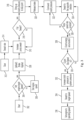
FIG. 3 is a block diagram depicting a process for setting a rotor speed of the combine. -
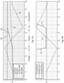
FIG. 4A is a graph depicting over time the speed of various components of the rotor drive system of the combine. -
FIG. 4B is a graph depicting over time the pressure of various components of the rotor drive system of the combine. - Aspects of the disclosure provide an agricultural vehicle having an engine, a threshing rotor, and a rotor drive system including a planetary gear assembly and a fluid circuit for driving the rotor at a constant acceleration during a start-up procedure of the rotor.
- Referring now to the drawings, and more particularly to
FIG. 1 , there is shown an agricultural harvester in the form of acombine 10, which generally includes achassis 12, groundengaging wheels header 18, afeeder housing 20, anoperator cab 22, a threshing and separatingsystem 24, acleaning system 26, agrain tank 28, and anunloading conveyance 30. Motive force is selectively applied to thefront wheels 14, and/or therear wheel 16, through a power plant in the form of anengine 32 and a transmission (not shown). - The
header 18 is mounted to the front of thecombine 10 and includes acutter bar 34 for severing crops from a field during forward motion ofcombine 10. Arotatable reel 36 feeds the crop into theheader 18, and adouble auger 38 feeds the severed crop laterally inwardly from each side toward thefeeder housing 20. The feeder housing 20 conveys the cut crop to threshing and the separatingsystem 24. - The threshing and separating
system 24 generally includes arotor 40 at least partially enclosed by and rotatable within a corresponding perforated concave 42. The cut crops are threshed and separated by the rotation of therotor 40 within the concave 42, and larger elements, such as stalks, leaves and the like are discharged from the rear of thecombine 10. Smaller elements of crop material are discharged through perforations of the concave 42. Grain that has been separated by the threshing and separatingassembly 24 falls onto agrain pan 44 and is conveyed toward thecleaning system 26. Further details of thecombine 10 are disclosed inU.S. Patent No. 9,907,228 -
FIG. 2 depicts a combine rotor hydro-mechanical CVT (continuously variable transmission)drive system 200 for drivingrotor 40 ofcombine 10. It should be understood at the outset thatsystem 200 is not limited for use withcombine 10, and the features and functions ofcombine 10 can vary greatly. -
System 200 provides a rotor drive with flexible speed selection and optimization for harvesting and threshing. In operation ofengine 32, for purpose of drivingrotor 40, power produced byengine 32 is split into two branches, namely, amechanical branch 202 and a hydraulic (or hydrostatic)branch 204.Branches planetary gear assembly 206. Agear box 205 having a plurality of interconnected gears is mechanically connected to and driven by an output shaft ofengine 32. Onegear 205a ofgear box 205 is connected to drivemechanical branch 202 and anothergear 205b ofgear box 205 is connected to drivehydraulic branch 204. Mechanical connections (e.g., shafts, gears, etc.) are depicted by solid lines inFIG. 2 . Of course, the arrangement ofgear box 205 can vary from that which is shown. - As shown in
FIG. 2 ,planetary gear assembly 206 comprises anouter ring gear 208 that is connected to asun gear 210 by a plurality of planet gears 212 (one shown). Planetgears 212 are each connected to acarrier 214. It should be understood that rotation ofring gear 208 and/orsun gear 210 causes rotation ofcarrier 214. Themechanical branch 202 is connected toring gear 208 for rotatingring gear 208, as desired. Thehydraulic branch 204 is connected tosun gear 210 for rotatingsun gear 210, as desired. InFIG. 2 it is noted that only the top halves ofgears other planet gears 212 are not shown.Gears gears carrier 214 can rotate simultaneously. - Power transmitted by
engine 32 ontogears carrier 214, which drivesrotor gearbox 216, which drivesrotor 40. As background, the rotational speed of the carrier (Nc) is given by the equation: Nc=(Ns*Zs + Nr*Zr)/(Zs+Zr); where c = carrier, s = sun gear, r = ring gear, Z = number of gear teeth, and N = speed (rpm). It should be understood that, during operation in hydro-mechanical mode, a reduction in the speed of sun gear (for example) will result in a reduction of the carrier speed (Nc), and, conversely, an increase in the speed of sun gear will result in an increase of the carrier speed (Nc). According to the embodiment ofplanetary gear assembly 206 shown herein, Zr is significantly greater than Zs, and, for at least that reason, the rotational speed of the carrier (Nc) will have a positive value (i.e., indicating forward rotation) during start-up ofrotor 40. - Turning now to
FIG. 2 ,carrier 214 is fixedly connected to the input of arotor gear box 216. While one gear set ofrotor gear box 216 is shown,rotor gear box 216 includes a plurality of gear sets for varying the output torque and speed of the output shaft ofgear box 216. The output shaft ofgear box 216 is fixedly connected torotor 40 for rotatingrotor 40. Aclutch 220 is connected betweengear 205a andring gear 208 for engaging and disengaging the power applied toring gear 208 byengine 32. Clutch 220 includes an input member (e.g., shaft) 220a connected togear 205a and an output member (e.g., shaft) 220b connected toring gear 208.Output member 220b includes agear 221 that is connected to (i.e., meshed with)ring gear 208. Gear 221 is non-rotatably connected tomember 220b. Abrake 222 is also connected tooutput member 220b for either stopping or slowingoutput member 220b, thereby either stopping or slowingring gear 208. -
Hydraulic branch 204 comprises a fluid circuit, afluid pump 230, which is powered byengine 32, and amotor 232.Fluid pump 230 drives motor 232, andmotor 232 rotatessun gear 210. - A
controller 238 is connected toengine 32,pump 230, clutch 220, and brake 222 (among other components) for controlling operation of those components. For example,controller 238 controls the swash rate and flow direction ofpump 230, as well as the engagement ofclutch 220, and the activation ofbrake 222. - As background to the invention, in the course of ramping-up
rotor 40, if one were to initially rotaterotor 40 usinghydraulic branch 204, and, thereafter, activatemechanical branch 202 to rotate rotor 40 (i.e., by fully engaging clutch 220), then therotor 40, with huge inertia, would generate vibrations due to the rapid acceleration from the speed produced by hydraulic branch 204 (e.g., 200 rpm) to the significantly higher speed produced by mechanical branch 202 (e.g., 1000 rpm). - Described hereinafter is a control strategy for ramping up the rotor speed, in the form of a method for ramping-up
rotor 40 to its target speed at constant acceleration. Constant acceleration ofrotor 40 yields a smooth and continuous startup process, which reduces vibrations, improves operator comfort, shortens the rotor engagement time and increases productivity. -
FIG. 3 will be described hereinafter with reference to the graphs shown inFIGs. 4A and 4B. FIG. 4A is a graph depicting over time the speed of various components ofrotor drive system 200. Depicted in the graph are the rotational speeds of ring gear 208 (labeled "RingSpeed", line 402), sun gear 210 (Sun-Motor Speed, line 404), rotor 40 (Rotor Speed, line 406), and the input speed of clutch 220 (Input Speed, line 408), which is also the speed ofgear 205a.FIG. 4B is a graph depicting over time the input control parameters of various components ofrotor drive system 200. Depicted in that graph are the operating pressures of clutch 220 (labeled "Normalized_clutch_P", line 412), brake 222 ("Normalized_Brake_P", line 414), and pump 230 (Pump Displacement, line 416). - Turning now to
FIGs. 3-4B , the process begins at 302 by activatingcombine 10. Atsteps engine 32, for example at 1000rpm. See alsostraight line 408 at time TO inFIG. 4A . Engine speed (optionally) remains constant through the rotor start-up process. Onceengine 32 begins operation,rotor 40 begins rotating in a hydrostatic drive mode (i.e., powered by hydraulic branch 204) while, atstep 308,brake 222 holdsring gear 208 stationary. During this time, atstep 310, pump 230 is swashed in the forward direction to acceleraterotor 40 to the maximum pure hydrostatic drive speed (i.e., full swash). See also lines 404 and 416 at time T1-T4 inFIGs. 4A and 4B , which depict a decrease in the pump displacement and an increase in the speed ofsun gear 210. Atsteps rotor gear box 216, a swash rate forpump 230 is defined that will limit the hydrostatic system pressure to a value below a relief setting. - Following
step 316, the "hydrostatic" stage ends and the "transition" stage begins at about time T4. - At
step 318, whenpump 230 has reached the maximum swash in the forward direction (as checked at step 316), the pressure ofclutch 220 is then increased to the kiss-point pressure. See also line 412 near time T4 inFIG. 4B . The term "kiss point" of a clutch is defined herein as the position of a clutch when the two halves of the clutch make initial frictional contact without transmitting any torque therebetween. - Following
step 318,brake 222 is released atstep 320. See also line 414 at time T4 onFIG. 4B , which depicts a reduction in braking pressure. Atstep 322, clutch 220 is partially engaged (i.e., modulated so that clutch 220 slips) and, consequently, transmits torque betweengear 205a of gear box 205 (input torque) andring gear 208 such thatring gear 208 is powered byengine 32. See also lines 402 and 412 at time T4-T7 inFIGs. 4A and 4B , which depicts an increased in the speed ofring gear 208 and an increase in the pressure ofclutch 220. At this transition stage,ring gear 208 transfers torque tocarrier 214, which rotatesrotor 40. It should be understood thatcarrier 214 always rotates in the same direction during the start-up process; and, likewise,rotor 40 always rotates in the same direction during the start-up process. - At or near the same time that the pressure of
clutch 220 is increasing and transferring torque to ringgear 208, atstep 324, pump 230 is swashed in the reverse direction, which switches the rotational direction ofsun gear 210 from a forward direction to a reverse direction. See also lines 404 and 416 at time T4-T7 inFIGs. 4A and 4B , which depict an increase in the pump displacement and a sharp decrease in the speed ofsun gear 210.Swashing pump 230 in the reverse direction atstep 324 to switch the rotational direction ofsun gear 210 reduces the gear ratio (i.e., applied torque) tocarrier 214. In other words, drivingsun gear 210 in the reverse direction counteracts the high torque/speed applied tocarrier 214 by ring gear 208 (via engine 32). Again, as noted above,gear 205a ofmechanical branch 202 drivesring gear 208 at a much higher speed thanmotor 232 ofhydraulic branch 204 drivessun gear 210. Drivingsun gear 210 in the reverse direction atstep 324 to counteract the higher torque/speed applied tocarrier 214 byring gear 208 yields a constant acceleration ofrotor 40. It should be understood that in the absence of the damping action provided bysun gear 210 atstep 324,rotor 40 would be immediately subjected to the full speed ofring gear 208, which would cause undesirable vibrations. - It is noted that, during the transition stage, the pressure overlap between
clutch 220 andbrake 222 during reversal of the pump swash (at step 324) preventsrotor 40 from inadvertently slowing down or "drooping" and promotes a straight-line constant acceleration ofrotor 40. Stated differently, during the transition stage, the combination of the (i) release ofbrake 222 bycontroller 238, (ii) modulation (i.e., partial engagement) ofclutch 220 through closed loop pressure control bycontroller 238, and (iii) reversal of the pump swash bycontroller 238, holds the rotor acceleration rate constant through the full engagement ofclutch 220, thereby avoiding the aforementioned undesirable vibrations ofrotor 40 during the start-up phase. The rotor speed ramp rate is made constant using a combination of input control signals. - At
step 326, the acceleration rate ofrotor 40 is monitored by a sensor (not shown) to ensure that the acceleration rate is constant. See the constant slope ofline 406 inFIG. 4A . If the acceleration rate is not constant, then the pressure ofclutch 220 is adjusted accordingly atstep 322. A PID loop, for example, may be utilized atsteps 322/326 to maintain a constant acceleration rate. - A large amount of heat is generated due to the partial engagement of
clutch 220. The temperature, or amount of energy, ofclutch 220 may be monitored atstep 328 to ensure thatclutch 220 does not overheat. - At
step 330, the slip speed ofclutch 220 is monitored. More particularly, the rotational speed ofring gear 208 is monitored and compared with the input drive speed atgear 205a . This comparison is indicative of the engagement condition ofclutch 220. Ifring gear 208 has not reached its drive speed (indicating thatclutch 220 is not fully engaged), the method returns to step 324 to modify the swash setting ofpump 230. Once the ring gear speed reaches its drive speed, which indicates that clutch is fully synchronized and not slipping, the pressure ofclutch 220 is increased atstep 332 until the clutch pressure reaches the system pressure and clutch 220 is fully engaged. See also lines 402 and 412 at time T6-T7 inFIGs. 4A and 4B , which depict increases in the ring gear speed and the clutch pressure.Clutch 220 remains fully engaged through the remainder of the rotor start-up process, which is depicted as the "hydromechanical" stage inFIG. 4A . Also, at the hydromechanical stage, the rotational speed ofring gear 208 matches the speed ofgear 205a (i.e., the engine speed) and the clutch 220 remains fully engaged (i.e., locked) through the remainder of the rotor start-up process as well as during operation. - At or near the same time as
step 332, atstep 334, the swash ofpump 230 is reversed again and commanded bycontroller 238 to swash in the forward direction and rotatesun gear 210 in the forward direction. At this time,motor 232 increases the speed ofsun gear 210, which increases the speed ofcarrier 214. See also lines 404 and 416 at time T7-T10 inFIGs. 4A and 4B . It is noted that combining the speeds (modulation) of thesun gear 210 andring gear 208 results in a constant acceleration ofcarrier 214, and, therefore, constant acceleration ofrotor 40. Seeline 406 at time T7-T10 inFIG. 4A . Atstep 336, the speed ofengine 32 may also be adjusted which would, consequently, adjust the speed ofrotor 40. - It is noted that the "constant" acceleration of
rotor 40 may not be perfectly constant. For example, a tolerance of +/- 5 % or 10% may be acceptable. - While the method herein describes operating the clutch in a partially engaged state for a limited period of time, it should be understood that the method could also be practiced by fully engaging clutch 220 and activating
brake 222 to slow rotation ofring gear 208 at time T4-T7. In such an alternative method, step 322 would be replaced by the step of fully engaging clutch 220, and a new step betweensteps brake 222 to slow rotation ofring gear 208. And, step 332 could be omitted. As another alternative to partially engaging clutch 220, though not as preferable, the speed ofengine 32 could be adjusted to slow rotation ofring gear 208 at time T4-T7. - Various components of
system 200 are controlled bycontroller 238, as is indicated by the lines inFIG. 2 . And, various steps of the method shown inFIG. 3 are performed bycontroller 238 upon loading and executing software code or instructions which are tangibly stored on a tangible computer readable medium, such as on a magnetic medium, e.g., a computer hard drive, an optical medium, e.g., an optical disc, solid-state memory, e.g., flash memory, or other storage media known in the art. Thus, any of the functionality performed by thecontroller 238 described herein, such as the steps shown inFIG. 3 , are implemented in software code or instructions which are tangibly stored on a tangible computer readable medium. Upon loading and executing such software code or instructions by thecontroller 238, thecontroller 238 may perform any of the functionality of thecontroller 238 described herein, including the steps shown inFIG. 3 described herein.
Claims (18)
- A method of rotating a threshing rotor (40) of an agricultural vehicle during a start-up procedure for the threshing rotor (40), the agricultural vehicle comprising an engine (32), the threshing rotor (40), a planetary gear assembly (206), and a fluid circuit,the planetary gear assembly (206) including(i) a first gear (208) that is mechanically connected to an output shaft of the engine,(ii) a second gear (210), and(iii) a carrier (214) that is mechanically connected to both the first gear (208) and the second gear (210), the carrier (214) also being connected to the threshing rotor (40) for driving the threshing rotor (40),the fluid circuit including(i) a reversible pump (230) that receives power from the engine (32) and(ii) a motor (232) that is fluidly connected to the pump (230) and has an output shaft that is connected to the second gear (210) for driving the second gear (210),wherein said method comprises the following steps:(a) operating the pump (230) to drive the motor (232) in a forward direction, which rotates the second gear (210) in a forward direction, which rotates the carrier (214) in a forward direction, which rotates the threshing rotor (40) in a forward direction, all while the first gear (208) remains stationary,(b) rotating the first gear (208), which rotates the carrier (214) in concert with the second gear (210) of step (a) while the threshing rotor (40) continues to rotate the threshing rotor (40) in the forward direction, and(c) operating the pump (230) on the fluid circuit to drive the motor (232) in a reverse direction, which rotates the second gear (210) in a reverse direction while the carrier (214) and the threshing rotor (40) continue to rotate in their forward directions, which step yields a substantially constant acceleration of the threshing rotor (40) over steps (a) through (c).
- The method of claim 1, wherein the method further comprises the step of braking the first gear (208) during step (a).
- The method of claim 2, wherein step (b) further comprises releasing the braking of the first gear (208).
- The method of claim 3, wherein step (c) comprises adjusting a position of a swash plate of the pump (230).
- The method of claim 3, wherein the vehicle further comprises a clutch (220) having an input member (220a) that is either directly or indirectly connected to the output shaft of the engine (32) and an output member (220b/221) that is connected to the first gear (208), wherein step (b) further comprises partially engaging and modulating the clutch (220) to drive rotation of the first gear (208).
- The method of any one of the preceding claims, wherein step (b) is initiated once the pump (230) reaches a full swash in step (a).
- The method of any one of the preceding claims, wherein, in step (c), rotating the second gear (210) in the reverse direction counteracts or dampens rotation of the carrier (214) attributed to rotation of the first gear (208).
- A method of rotating a threshing rotor (40) of an agricultural vehicle during a start-up procedure for the threshing rotor (40), the agricultural vehicle comprising an engine (32), the threshing rotor (40), a planetary gear assembly (206), a clutch (220), and a fluid circuit,the planetary gear assembly including(i) a first gear (208) that is mechanically connected to an output shaft of the engine,(ii) a second gear (210), and(iii) a carrier (214) that is mechanically connected to both the first gear (208) and the second gear (210), the carrier (214) also being connected to the threshing rotor (40) for driving the threshing rotor (40),the clutch (220) having an input member (220a) that is either directly or indirectly connected to the output shaft of the engine (32) and an output member (220b/221) that is connected to the first gear (208)the fluid circuit including(i) a reversible pump (230) that receives power from the engine and(ii) a motor (232) that is fluidly connected to the pump (230) and has an output shaft that is connected to the second gear (210) for driving the second gear (210),wherein said method comprises the following steps:(a) operating the pump (230) to drive the motor (232) in a forward direction, which rotates the second gear (210) in a forward direction, which rotates the carrier (214) in a forward direction, which rotates the threshing rotor (40) in a forward direction, all while the first gear (208) remains stationary,(b) partially engaging the clutch (220) to rotate the output member (220b/221) of the clutch (220), which rotates the first gear (208), which rotates the carrier (214) in concert with the second gear (210) of step (a) while the threshing rotor (40) continues to rotate in the forward direction, and(c) operating the pump (230) on the fluid circuit to drive the motor (232) in a reverse direction, which rotates the second gear (210) in a reverse direction while the carrier (214) and the threshing rotor (40) continue to rotate in their respective forward directions, which step yields a substantially constant acceleration of the threshing rotor (40) over steps (a) through (c).
- The method of claim 8, wherein the method further comprises the step of braking the first gear (208) during step (a).
- The method of claim 9, wherein step (b) further comprises releasing the braking of the first gear (208).
- The method of claim 9, wherein step (c) comprises adjusting a position of a swash plate of the pump (230).
- The method of any one of claims 8-11, wherein the method further comprises the step of:
(d) fully engaging the clutch (220) to rotate the output member (220b/221) of the clutch (220) at a faster speed, and, therefore, rotate the threshing rotor (40) in the forward direction at a faster speed. - The method of claim 12, wherein the method further comprises the step of:
(e) operating the pump (230) to drive the motor (232) in the forward direction, which rotates the second gear (210) in the forward direction, which rotates the carrier (214) in the forward direction in concert with the first gear (208), which rotates the threshing rotor (40) in the forward direction, which yields a substantially constant acceleration of the threshing rotor (40) over steps (a) through (e). - The method of claim 13, wherein the first gear (208) rotates in a same direction through steps (b) through (e), and the threshing rotor (40) rotates in a same direction through steps (a) through (e).
- The method of claim 13, wherein step (e) is initiated after step (d).
- The method of any one of claims 8-15, wherein step (b) is initiated once the pump (230) reaches a full swash in step (a).
- The method of any one of claims 8-16, wherein, in step (c), rotating the second gear (210) in the reverse direction counteracts or dampens rotation of the carrier (214) attributed to rotation of the first gear (208).
- A method of starting a threshing rotor (40) of an agricultural vehicle, the agricultural vehicle comprising an engine (32), the threshing rotor (40), and a rotor drive system comprising a hydraulic branch (204) and a separate mechanical branch (202) that each receive power from the engine (32), wherein the method of starting the threshing rotor (40) comprises activating the threshing rotor (40) using the hydraulic branch (204) and the mechanical branch (202) while maintaining a constant acceleration of the threshing rotor (40).
Applications Claiming Priority (1)
| Application Number | Priority Date | Filing Date | Title |
|---|---|---|---|
| US17/527,704 US12336456B2 (en) | 2021-11-16 | 2021-11-16 | Control system and method for increasing rotor speed during combine rotor start-up |
Publications (2)
| Publication Number | Publication Date |
|---|---|
| EP4179866A1 true EP4179866A1 (en) | 2023-05-17 |
| EP4179866B1 EP4179866B1 (en) | 2025-02-19 |
Family
ID=84358030
Family Applications (1)
| Application Number | Title | Priority Date | Filing Date |
|---|---|---|---|
| EP22207459.3A Active EP4179866B1 (en) | 2021-11-16 | 2022-11-15 | Control system and method for increasing rotor speed during combine rotor start-up |
Country Status (2)
| Country | Link |
|---|---|
| US (1) | US12336456B2 (en) |
| EP (1) | EP4179866B1 (en) |
Citations (4)
| Publication number | Priority date | Publication date | Assignee | Title |
|---|---|---|---|---|
| US6059656A (en) * | 1998-05-28 | 2000-05-09 | Caterpillar Inc. | Variable speed drive system for a system for a rotor assembly of a grain threshing mechanism |
| EP1382885A1 (en) * | 2002-07-19 | 2004-01-21 | CNH Belgium N.V. | Method for re-engaging a dual power path drive for a rotating threshing rotor of an agricultural combine |
| EP1382891A2 (en) * | 2002-07-19 | 2004-01-21 | CNH Belgium N.V. | Work vehicle including start-up control current calibration mechanism for proportional control systems |
| US9907228B2 (en) | 2015-06-10 | 2018-03-06 | Cnh Industrial America Llc | Grain tank with force assisting element for cover |
Family Cites Families (18)
| Publication number | Priority date | Publication date | Assignee | Title |
|---|---|---|---|---|
| DE4303243C2 (en) | 1993-02-04 | 1995-04-13 | Linde Ag | Method for comparing the characteristics of continuously variable transmissions of a vehicle with double-sided drive |
| US5873227A (en) | 1997-11-04 | 1999-02-23 | Agco Corporation | Combine harvester rotor speed control and control method |
| US7062368B2 (en) * | 2002-06-11 | 2006-06-13 | Cnh America Llc | Combine having a system estimator to automatically estimate and dynamically change a target control parameter in a control algorithm |
| US6702666B2 (en) * | 2002-06-11 | 2004-03-09 | Case, Llc | Combine having a system estimator to monitor hydraulic system pressure |
| US6695693B2 (en) * | 2002-06-11 | 2004-02-24 | Case Llc | Combine having a system estimator to monitor hydraulic system pressure |
| US6726560B2 (en) * | 2002-07-19 | 2004-04-27 | Cnh America Llc | Dual power path drive for a rotating threshing rotor of an agricultural combine and method for re-engaging the same |
| US7186201B2 (en) * | 2005-02-04 | 2007-03-06 | Cnh America Llc | Active combine rotor deceleration |
| US20080034720A1 (en) | 2006-08-11 | 2008-02-14 | Helfrich James C | Engine load control for hydrostaticaly driven equipment |
| AT504432B8 (en) * | 2006-10-24 | 2008-09-15 | Hofer Forschungs & Entw Gmbh | POWER PLANT FOR A MOTOR VEHICLE |
| US8074433B2 (en) | 2008-03-14 | 2011-12-13 | Deere & Company | Agricultural harvester with auxiliary power unit and intelligent power management |
| US8517133B2 (en) * | 2009-07-17 | 2013-08-27 | Parker-Hannifin Corporation | System including output coupled powersplit transmission |
| JP2011188780A (en) | 2010-03-12 | 2011-09-29 | Iseki & Co Ltd | Combine harvester |
| GB201117720D0 (en) * | 2011-10-13 | 2011-11-23 | Agco Int Gmbh | Method to determine vehicle weight |
| US8781694B1 (en) | 2013-02-15 | 2014-07-15 | Deere & Company | Combine harvester drive system |
| JP6313965B2 (en) * | 2013-12-13 | 2018-04-18 | 株式会社小松製作所 | Work vehicle and control method thereof |
| JP6630030B2 (en) * | 2014-01-31 | 2020-01-15 | 株式会社小松製作所 | Wheel loader and wheel loader control method |
| EP2955074B1 (en) * | 2014-06-13 | 2020-11-04 | Perkins Engines Company Limited | A variator-assisted transmission and launch control methods for such a transmission |
| JP6542084B2 (en) | 2015-09-17 | 2019-07-10 | ヤンマー株式会社 | Combine |
-
2021
- 2021-11-16 US US17/527,704 patent/US12336456B2/en active Active
-
2022
- 2022-11-15 EP EP22207459.3A patent/EP4179866B1/en active Active
Patent Citations (4)
| Publication number | Priority date | Publication date | Assignee | Title |
|---|---|---|---|---|
| US6059656A (en) * | 1998-05-28 | 2000-05-09 | Caterpillar Inc. | Variable speed drive system for a system for a rotor assembly of a grain threshing mechanism |
| EP1382885A1 (en) * | 2002-07-19 | 2004-01-21 | CNH Belgium N.V. | Method for re-engaging a dual power path drive for a rotating threshing rotor of an agricultural combine |
| EP1382891A2 (en) * | 2002-07-19 | 2004-01-21 | CNH Belgium N.V. | Work vehicle including start-up control current calibration mechanism for proportional control systems |
| US9907228B2 (en) | 2015-06-10 | 2018-03-06 | Cnh Industrial America Llc | Grain tank with force assisting element for cover |
Also Published As
| Publication number | Publication date |
|---|---|
| EP4179866B1 (en) | 2025-02-19 |
| US20230148477A1 (en) | 2023-05-18 |
| US12336456B2 (en) | 2025-06-24 |
Similar Documents
| Publication | Publication Date | Title |
|---|---|---|
| JP5244813B2 (en) | Differential gear of a wind energy plant and method for changing or switching the power range of this differential gear | |
| US20050014603A1 (en) | Hydro-mechanical threshing rotor control system for an agricultural combine | |
| EP1382889B1 (en) | Method of operation of a hydro-mechanical transmission with automatic braking capability. | |
| US9470307B2 (en) | Method for operating a vehicle drive train | |
| EP1072817A3 (en) | Hydro-mechanical transmission system for an agricultural harvesting machine | |
| JP7193838B2 (en) | work vehicle | |
| KR20080016582A (en) | Automotive power take-off | |
| EP4179866B1 (en) | Control system and method for increasing rotor speed during combine rotor start-up | |
| JP2000145924A (en) | Apparatus and method for controlling negative load of engine related to hydro-mechanical drive system | |
| CN108025639A (en) | Implement the transmission system of automatic direction transformation braking | |
| US7200980B2 (en) | Drive system of a self-propelled working machine | |
| US7213389B2 (en) | Infinitely variable transmission for a combine header unit | |
| EP1688029B1 (en) | Active combine rotor deceleration. | |
| WO1995027160A1 (en) | Method of power transmission in mechanical/hydraulic type transmission | |
| US10322723B2 (en) | Variator-assisted transmission and launch control methods for such a transmission | |
| EP3819736A1 (en) | Agricultural system | |
| BR102022022979A2 (en) | METHODS FOR TURNING A ROTOR DURING A STARTING PROCEDURE AND METHOD OF STARTING A ROTOR | |
| EP1382885B1 (en) | Method for re-engaging a dual power path drive for a rotating threshing rotor of an agricultural combine | |
| KR101710753B1 (en) | Combine | |
| US11364796B2 (en) | Kinetic energy recovery system | |
| JP5457792B2 (en) | Control device for traveling transmission | |
| KR102821430B1 (en) | Combine | |
| JP3702876B2 (en) | Combine harvester gearing | |
| WO2025197407A1 (en) | Work vehicle | |
| JP5255550B2 (en) | Movable harvester travel transmission |
Legal Events
| Date | Code | Title | Description |
|---|---|---|---|
| PUAI | Public reference made under article 153(3) epc to a published international application that has entered the european phase |
Free format text: ORIGINAL CODE: 0009012 |
|
| STAA | Information on the status of an ep patent application or granted ep patent |
Free format text: STATUS: THE APPLICATION HAS BEEN PUBLISHED |
|
| AK | Designated contracting states |
Kind code of ref document: A1 Designated state(s): AL AT BE BG CH CY CZ DE DK EE ES FI FR GB GR HR HU IE IS IT LI LT LU LV MC ME MK MT NL NO PL PT RO RS SE SI SK SM TR |
|
| STAA | Information on the status of an ep patent application or granted ep patent |
Free format text: STATUS: REQUEST FOR EXAMINATION WAS MADE |
|
| 17P | Request for examination filed |
Effective date: 20231117 |
|
| RBV | Designated contracting states (corrected) |
Designated state(s): AL AT BE BG CH CY CZ DE DK EE ES FI FR GB GR HR HU IE IS IT LI LT LU LV MC ME MK MT NL NO PL PT RO RS SE SI SK SM TR |
|
| GRAP | Despatch of communication of intention to grant a patent |
Free format text: ORIGINAL CODE: EPIDOSNIGR1 |
|
| STAA | Information on the status of an ep patent application or granted ep patent |
Free format text: STATUS: GRANT OF PATENT IS INTENDED |
|
| INTG | Intention to grant announced |
Effective date: 20240913 |
|
| GRAS | Grant fee paid |
Free format text: ORIGINAL CODE: EPIDOSNIGR3 |
|
| GRAA | (expected) grant |
Free format text: ORIGINAL CODE: 0009210 |
|
| STAA | Information on the status of an ep patent application or granted ep patent |
Free format text: STATUS: THE PATENT HAS BEEN GRANTED |
|
| AK | Designated contracting states |
Kind code of ref document: B1 Designated state(s): AL AT BE BG CH CY CZ DE DK EE ES FI FR GB GR HR HU IE IS IT LI LT LU LV MC ME MK MT NL NO PL PT RO RS SE SI SK SM TR |
|
| REG | Reference to a national code |
Ref country code: GB Ref legal event code: FG4D |
|
| REG | Reference to a national code |
Ref country code: CH Ref legal event code: EP |
|
| REG | Reference to a national code |
Ref country code: IE Ref legal event code: FG4D |
|
| REG | Reference to a national code |
Ref country code: DE Ref legal event code: R096 Ref document number: 602022010782 Country of ref document: DE |
|
| REG | Reference to a national code |
Ref country code: NL Ref legal event code: MP Effective date: 20250219 |
|
| PG25 | Lapsed in a contracting state [announced via postgrant information from national office to epo] |
Ref country code: RS Free format text: LAPSE BECAUSE OF FAILURE TO SUBMIT A TRANSLATION OF THE DESCRIPTION OR TO PAY THE FEE WITHIN THE PRESCRIBED TIME-LIMIT Effective date: 20250519 |
|
| PG25 | Lapsed in a contracting state [announced via postgrant information from national office to epo] |
Ref country code: FI Free format text: LAPSE BECAUSE OF FAILURE TO SUBMIT A TRANSLATION OF THE DESCRIPTION OR TO PAY THE FEE WITHIN THE PRESCRIBED TIME-LIMIT Effective date: 20250219 |
|
| PG25 | Lapsed in a contracting state [announced via postgrant information from national office to epo] |
Ref country code: PL Free format text: LAPSE BECAUSE OF FAILURE TO SUBMIT A TRANSLATION OF THE DESCRIPTION OR TO PAY THE FEE WITHIN THE PRESCRIBED TIME-LIMIT Effective date: 20250219 |
|
| PG25 | Lapsed in a contracting state [announced via postgrant information from national office to epo] |
Ref country code: ES Free format text: LAPSE BECAUSE OF FAILURE TO SUBMIT A TRANSLATION OF THE DESCRIPTION OR TO PAY THE FEE WITHIN THE PRESCRIBED TIME-LIMIT Effective date: 20250219 |
|
| REG | Reference to a national code |
Ref country code: LT Ref legal event code: MG9D |
|
| PG25 | Lapsed in a contracting state [announced via postgrant information from national office to epo] |
Ref country code: IS Free format text: LAPSE BECAUSE OF FAILURE TO SUBMIT A TRANSLATION OF THE DESCRIPTION OR TO PAY THE FEE WITHIN THE PRESCRIBED TIME-LIMIT Effective date: 20250619 Ref country code: NO Free format text: LAPSE BECAUSE OF FAILURE TO SUBMIT A TRANSLATION OF THE DESCRIPTION OR TO PAY THE FEE WITHIN THE PRESCRIBED TIME-LIMIT Effective date: 20250519 |
|
| PG25 | Lapsed in a contracting state [announced via postgrant information from national office to epo] |
Ref country code: NL Free format text: LAPSE BECAUSE OF FAILURE TO SUBMIT A TRANSLATION OF THE DESCRIPTION OR TO PAY THE FEE WITHIN THE PRESCRIBED TIME-LIMIT Effective date: 20250219 |
|
| PG25 | Lapsed in a contracting state [announced via postgrant information from national office to epo] |
Ref country code: HR Free format text: LAPSE BECAUSE OF FAILURE TO SUBMIT A TRANSLATION OF THE DESCRIPTION OR TO PAY THE FEE WITHIN THE PRESCRIBED TIME-LIMIT Effective date: 20250219 |
|
| PG25 | Lapsed in a contracting state [announced via postgrant information from national office to epo] |
Ref country code: PT Free format text: LAPSE BECAUSE OF FAILURE TO SUBMIT A TRANSLATION OF THE DESCRIPTION OR TO PAY THE FEE WITHIN THE PRESCRIBED TIME-LIMIT Effective date: 20250620 Ref country code: LV Free format text: LAPSE BECAUSE OF FAILURE TO SUBMIT A TRANSLATION OF THE DESCRIPTION OR TO PAY THE FEE WITHIN THE PRESCRIBED TIME-LIMIT Effective date: 20250219 |
|
| PG25 | Lapsed in a contracting state [announced via postgrant information from national office to epo] |
Ref country code: BG Free format text: LAPSE BECAUSE OF FAILURE TO SUBMIT A TRANSLATION OF THE DESCRIPTION OR TO PAY THE FEE WITHIN THE PRESCRIBED TIME-LIMIT Effective date: 20250219 Ref country code: GR Free format text: LAPSE BECAUSE OF FAILURE TO SUBMIT A TRANSLATION OF THE DESCRIPTION OR TO PAY THE FEE WITHIN THE PRESCRIBED TIME-LIMIT Effective date: 20250520 |
|
| REG | Reference to a national code |
Ref country code: AT Ref legal event code: MK05 Ref document number: 1767370 Country of ref document: AT Kind code of ref document: T Effective date: 20250219 |
|
| PG25 | Lapsed in a contracting state [announced via postgrant information from national office to epo] |
Ref country code: SE Free format text: LAPSE BECAUSE OF FAILURE TO SUBMIT A TRANSLATION OF THE DESCRIPTION OR TO PAY THE FEE WITHIN THE PRESCRIBED TIME-LIMIT Effective date: 20250219 |
|
| PG25 | Lapsed in a contracting state [announced via postgrant information from national office to epo] |
Ref country code: SM Free format text: LAPSE BECAUSE OF FAILURE TO SUBMIT A TRANSLATION OF THE DESCRIPTION OR TO PAY THE FEE WITHIN THE PRESCRIBED TIME-LIMIT Effective date: 20250219 |
|
| PG25 | Lapsed in a contracting state [announced via postgrant information from national office to epo] |
Ref country code: DK Free format text: LAPSE BECAUSE OF FAILURE TO SUBMIT A TRANSLATION OF THE DESCRIPTION OR TO PAY THE FEE WITHIN THE PRESCRIBED TIME-LIMIT Effective date: 20250219 |
|
| PG25 | Lapsed in a contracting state [announced via postgrant information from national office to epo] |
Ref country code: IT Free format text: LAPSE BECAUSE OF FAILURE TO SUBMIT A TRANSLATION OF THE DESCRIPTION OR TO PAY THE FEE WITHIN THE PRESCRIBED TIME-LIMIT Effective date: 20250219 |
|
| PG25 | Lapsed in a contracting state [announced via postgrant information from national office to epo] |
Ref country code: AT Free format text: LAPSE BECAUSE OF FAILURE TO SUBMIT A TRANSLATION OF THE DESCRIPTION OR TO PAY THE FEE WITHIN THE PRESCRIBED TIME-LIMIT Effective date: 20250219 |
|
| PG25 | Lapsed in a contracting state [announced via postgrant information from national office to epo] |
Ref country code: EE Free format text: LAPSE BECAUSE OF FAILURE TO SUBMIT A TRANSLATION OF THE DESCRIPTION OR TO PAY THE FEE WITHIN THE PRESCRIBED TIME-LIMIT Effective date: 20250219 Ref country code: CZ Free format text: LAPSE BECAUSE OF FAILURE TO SUBMIT A TRANSLATION OF THE DESCRIPTION OR TO PAY THE FEE WITHIN THE PRESCRIBED TIME-LIMIT Effective date: 20250219 |
|
| PG25 | Lapsed in a contracting state [announced via postgrant information from national office to epo] |
Ref country code: RO Free format text: LAPSE BECAUSE OF FAILURE TO SUBMIT A TRANSLATION OF THE DESCRIPTION OR TO PAY THE FEE WITHIN THE PRESCRIBED TIME-LIMIT Effective date: 20250219 |
|
| PG25 | Lapsed in a contracting state [announced via postgrant information from national office to epo] |
Ref country code: SK Free format text: LAPSE BECAUSE OF FAILURE TO SUBMIT A TRANSLATION OF THE DESCRIPTION OR TO PAY THE FEE WITHIN THE PRESCRIBED TIME-LIMIT Effective date: 20250219 |
|
| REG | Reference to a national code |
Ref country code: DE Ref legal event code: R097 Ref document number: 602022010782 Country of ref document: DE |
|
| PLBE | No opposition filed within time limit |
Free format text: ORIGINAL CODE: 0009261 |
|
| STAA | Information on the status of an ep patent application or granted ep patent |
Free format text: STATUS: NO OPPOSITION FILED WITHIN TIME LIMIT |
|
| PGFP | Annual fee paid to national office [announced via postgrant information from national office to epo] |
Ref country code: DE Payment date: 20251126 Year of fee payment: 4 |
|
| 26N | No opposition filed |
Effective date: 20251120 |