EP4179622B1 - Verfahren zur ermittlung der wicklungstemperatur eines elektromotors - Google Patents
Verfahren zur ermittlung der wicklungstemperatur eines elektromotors Download PDFInfo
- Publication number
- EP4179622B1 EP4179622B1 EP22737735.5A EP22737735A EP4179622B1 EP 4179622 B1 EP4179622 B1 EP 4179622B1 EP 22737735 A EP22737735 A EP 22737735A EP 4179622 B1 EP4179622 B1 EP 4179622B1
- Authority
- EP
- European Patent Office
- Prior art keywords
- temperature
- winding
- electric motor
- resistance
- reference point
- Prior art date
- Legal status (The legal status is an assumption and is not a legal conclusion. Google has not performed a legal analysis and makes no representation as to the accuracy of the status listed.)
- Active
Links
Images
Classifications
-
- H—ELECTRICITY
- H02—GENERATION; CONVERSION OR DISTRIBUTION OF ELECTRIC POWER
- H02P—CONTROL OR REGULATION OF ELECTRIC MOTORS, ELECTRIC GENERATORS OR DYNAMO-ELECTRIC CONVERTERS; CONTROLLING TRANSFORMERS, REACTORS OR CHOKE COILS
- H02P29/00—Arrangements for regulating or controlling electric motors, appropriate for both AC and DC motors
- H02P29/60—Controlling or determining the temperature of the motor or of the drive
- H02P29/64—Controlling or determining the temperature of the winding
-
- H—ELECTRICITY
- H02—GENERATION; CONVERSION OR DISTRIBUTION OF ELECTRIC POWER
- H02H—EMERGENCY PROTECTIVE CIRCUIT ARRANGEMENTS
- H02H6/00—Emergency protective circuit arrangements responsive to undesired changes from normal non-electric working conditions using simulators of the apparatus being protected, e.g. using thermal images
-
- H—ELECTRICITY
- H02—GENERATION; CONVERSION OR DISTRIBUTION OF ELECTRIC POWER
- H02H—EMERGENCY PROTECTIVE CIRCUIT ARRANGEMENTS
- H02H7/00—Emergency protective circuit arrangements specially adapted for specific types of electric machines or apparatus or for sectionalised protection of cable or line systems, and effecting automatic switching in the event of an undesired change from normal working conditions
- H02H7/08—Emergency protective circuit arrangements specially adapted for specific types of electric machines or apparatus or for sectionalised protection of cable or line systems, and effecting automatic switching in the event of an undesired change from normal working conditions for dynamo-electric motors
- H02H7/085—Emergency protective circuit arrangements specially adapted for specific types of electric machines or apparatus or for sectionalised protection of cable or line systems, and effecting automatic switching in the event of an undesired change from normal working conditions for dynamo-electric motors against excessive load
-
- H—ELECTRICITY
- H02—GENERATION; CONVERSION OR DISTRIBUTION OF ELECTRIC POWER
- H02H—EMERGENCY PROTECTIVE CIRCUIT ARRANGEMENTS
- H02H5/00—Emergency protective circuit arrangements for automatic disconnection directly responsive to an undesired change from normal non-electric working conditions with or without subsequent reconnection
- H02H5/04—Emergency protective circuit arrangements for automatic disconnection directly responsive to an undesired change from normal non-electric working conditions with or without subsequent reconnection responsive to abnormal temperature
Definitions
- the invention relates to a method for determining the winding temperature of an electric motor comprising a microcontroller (MCU), in particular a permanent magnet synchronous motor (PMSM), preferably as a drive for a fan.
- MCU microcontroller
- PMSM permanent magnet synchronous motor
- Losses in an electric motor cause the active components, such as the winding and any laminated cores, to heat up.
- the increase in winding temperature reduces the service life of the insulation and can even lead to immediate failure of the electric motor.
- the cause of an unacceptable temperature increase can be insufficient cooling or overload, with overload resulting in increased current consumption of the electric motor. Permissible temperature limits can quickly be exceeded.
- the DE102014005706A1 discloses a method for operating an electric motor with a motor temperature model that determines the winding temperature from an initial temperature and a winding resistance.
- the invention is based on the object of providing a simple method for determining the winding temperature of an electric motor, which eliminates the need for additional sensors.
- it should be possible to measure the winding temperature of a permanent magnet synchronous motor, which is usually controlled in a field-oriented manner, both when the electric motor is at a standstill and during operation.
- the method according to the invention should differ from corresponding competitor methods.
- the above object is achieved by the features of claim 1.
- the method according to the invention is characterized in that the winding temperature is determined using known or ascertainable parameters of the electric motor, based on a reference point consisting of a reference temperature and a winding resistance at the reference temperature.
- the core idea of the invention is the creation of a reference point comprising a reference temperature and a winding resistance at the reference temperature. Starting from this reference point, the winding temperature can be determined taking known parameters into account.
- ambient temperature which is simply the ambient temperature of the production facility.
- the temperature from a preferably calibrated temperature measurement on the power electronics can be equated to the winding temperature, so that the value pair from the temperature of a calibrated temperature sensor located on the circuit board and thus the winding temperature and the conventionally determined winding resistance serve as a reference point for further determination of the winding temperature during operation of the electric motor.
- the temperature does not necessarily have to be measured on the power electronics. It is also conceivable to use the room temperature of the production facility. If temperature sensors are located on the aforementioned components, these temperature sensors are preferred.
- the winding resistance can be determined conventionally, for example using a known test procedure or mathematical models.
- the so-called injection method can be used as a test method, whereby electrical test pulses are applied to the winding, from which the electrical resistance of the winding can be determined.
- the reference point and its two values can be stored in an external memory or in the MCU's memory.
- a comparison of the winding resistance with the temperature of a temperature sensor located on the board, and thus the initial winding temperature, is performed only once during production to define the reference point and store it accordingly.
- the external memory can be, for example, an EEPROM.
- the current absolute winding temperature can be determined at any time during the operating period.
- the current winding temperature as a parameter in the context of predictive maintenance, for example to obtain information about the operating behavior of the electric motor and to be able to estimate or even predict possible damage or failures of the electric motor due to thermal stress.
- knowledge of the winding temperature over the course of operation can also be used in the approval process to benefit the process with regard to knowledge of the winding temperature and to accelerate the process.
- the reference point is/will be stored in a non-volatile memory, for example, in the memory of the MCU.
- the winding resistance is determined in the conventional way, for example, using an injection method with test pulses or using parameter estimators.
- the current absolute winding temperature can be determined according to the above explanations in the general section of the description. This value can be used, for example, for predictive maintenance and can be fed into a corresponding model.
Landscapes
- Engineering & Computer Science (AREA)
- Power Engineering (AREA)
- Control Of Ac Motors In General (AREA)
- Control Of Electric Motors In General (AREA)
Description
- Die Erfindung betrifft ein Verfahren zur Ermittlung der Wicklungstemperatur eines einen Mikrocontroller (MCU) umfassenden Elektromotors, insbesondere eines Permanentmagnet-Synchronmotors (PMSM), vorzugsweise als Antrieb für einen Ventilator.
- Verluste eines Elektromotors bewirken eine Erwärmung der aktiven Teile wie der Wicklung und etwaiger Blechpakete. Die Erhöhung der Wicklungstemperatur verringert die Lebensdauer der Isolierung und kann sogar zum sofortigen Ausfall des Elektromotors führen.
- Die Ursache unzulässiger Temperaturerhöhung kann mangelnde Kühlung oder Überlastung sein, wobei eine Überlastung eine erhöhte Stromaufnahme des Elektromotors zur Folge hat. Zulässige Grenzen der Erwärmung können schnell überschritten werden.
- Entsprechend ist es von Bedeutung, sowohl im Stillstand wie auch im Betrieb eines Elektromotors die Wicklungstemperatur zu kennen. Diese Kenntnis begünstigt den Zulassungsprozess des Elektromotors und hilft insbesondere im Rahmen der vorausschauenden Instandhaltung die Lebensdauer eines Elektromotors abzuschätzen und unter Zugrundelegung entsprechender Maßnahmen zu verlängern.
- Aus der Praxis ist es bekannt, die Wicklungstemperatur eines Elektromotors unter Nutzung eingebauter Temperatursensoren zu ermitteln. Dies ist regelmäßig mit einem hohen messtechnischen Aufwand verbunden und erhöht die Fertigungskosten. Außerdem sind eingebaute Temperatursensoren nur schwer wartbar.
- Derzeit ist es auch mit sehr komplexen mathematischen Modellen nur bedingt möglich, die Wicklungstemperatur eines Elektromotors in jedem Betriebspunkt (Stillstand, Normalbetrieb, Feldschwächenbetrieb, etc.) mit der erforderlichen Genauigkeit zu messen. Handelt es sich bei dem Elektromotor um einen Antrieb für einen Ventilator, ist regelmäßig eine sicherheitsrelevante Software vorgesehen, die den Ventilator abschaltet, bevor der Elektromotor einen kritischen Zustand erreicht. Um eine Sicherheitsabschaltung auch ohne die Vorkehrung eines Temperatursensors in der Wicklung sicherzustellen, sind aufwändige Messungen nötig, um indirekt über vorhandene Messgrößen eine Temperaturabschaltung zu ermöglichen.
- Die
DE102014005706A1 offenbart ein Verfahren zum Betreiben eines Elektromotors mit einem Motortemperaturmodell, das aus einer Ausgangstemperatur und einem Wicklungswiderstand die Wicklungstemperatur ermittelt. - Der Erfindung liegt die Aufgabe zugrunde, ein einfaches Verfahren zur Ermittlung der Wicklungstemperatur eines Elektromotors anzugeben, wonach zusätzliche Sensoren nicht erforderlich sind. Insbesondere soll es möglich sein, die Wicklungstemperatur eines Permanentmagnet-Synchronmotors, der üblicherweise feldorientiert geregelt wird, sowohl im Stillstand als auch im Betrieb des Elektromotors messen zu können. Außerdem soll sich das erfindungsgemäße Verfahren von entsprechenden Verfahren des Wettbewerbs unterscheiden.
- Voranstehende Aufgabe ist durch die Merkmale des Anspruchs 1 gelöst. Danach ist das erfindungsgemäße Verfahren dadurch gekennzeichnet, dass die Wicklungstemperatur mithilfe bekannter oder ermittelbarer Parameter des Elektromotors unter Zugrundelegung eines Referenzpunktes aus einer Referenztemperatur und einem Wicklungswiderstand bei der Referenztemperatur ermittelt wird. Kerngedanke der Erfindung ist die Schaffung eines Referenzpunktes, der eine Referenztemperatur und einen Wicklungswiderstand bei der Referenztemperatur umfasst. Ausgehend von diesem Referenzpunkt lässt sich die Wicklungstemperatur unter Berücksichtigung bekannter Parameter ermitteln.
- Im Konkreten wird vorausgesetzt, dass vor einer ersten Inbetriebnahme des Elektromotors alle Komponenten die Temperatur der Umgebung haben, wobei es sich dabei schlichtweg um die Umgebungstemperatur der Produktionsstätte handelt. Im Konkreten kann die Temperatur aus einer vorzugsweise kalibrierten Temperaturmessung an der Leistungselektronik (beispielsweise MCU, ZK-Elko, IGBT, etc.) der Wicklungstemperatur gleichgesetzt werden, so dass das Wertepaar aus der Temperatur eines sich auf der Platine befindlichen, kalibrierten Temperatursensors und somit der Wicklungstemperatur und dem auf herkömmliche Weise ermittelbaren Wicklungswiderstand als Referenzpunkt für die weitere Bestimmung der Wicklungstemperatur im Betrieb des Elektromotors dient. An dieser Stelle sei angemerkt, dass die Temperatur nicht zwangsläufig auf der Leistungselektronik gemessen werden muss. Ebenso ist es denkbar, die Raumtemperatur der Produktionsstätte zu verwenden. Sofern sich Temperatursensoren auf den genannten Bauteilen befinden, werden diese Temperatursensoren vorzugsweise genutzt.
- Der Wicklungswiderstand lässt sich herkömmlich ermitteln, beispielsweise über ein bekanntes Testverfahren oder über mathematische Modelle.
- Als Testverfahren kommen sog. Injektionsverfahren in Frage, wonach elektrische Testimpulse auf die Wicklung gegeben werden, woraus sich der elektrische Widerstand der Wicklung bestimmen lässt.
- An dieser Stelle sie noch einmal betont, dass es hier um die Kombination aus dem Wicklungswiderstand und der Temperatur eines auf der Platine befindlichen Temperatursensors (= anfängliche Wicklungstemperatur) geht, wobei dieser Referenzpunkt zur Bestimmung der Wicklungstemperatur im Betrieb des Elektromotors genutzt wird.
- Der Referenzpunkt mit seinen beiden Werten kann in einem externen Speicher oder in einem Speicher der MCU abgelegt werden, wobei ein Abgleich des Wicklungswiderstands mit der Temperatur eines auf der Platine befindlichen Temperatursensors und somit der anfänglichen Wicklungstemperatur nur einmal in der Produktion vorgenommen wird, um den Referenzpunkt zu definieren und entsprechend abzulegen. Bei dem externen Speicher kann es sich beispielsweise um einen EEPROM handeln.
- Zur andauernden oder periodischen Ermittlung der Wicklungstemperatur kann der Wicklungswiderstand zyklisch nach dem zuvor erörterten bekannten Verfahren, d.h. wie vor der ersten Inbetriebnahme, ermittelt werden. Die Temperaturerhöhung der Wicklung lässt sich über die Änderung des Wicklungswiderstands wie folgt berechnen:

- Δϑ die Temperaturerhöhung der Wicklung gegenüber der Referenztemperatur,
- R der aktuelle Wicklungswiderstand,
- RRef der Wicklungswiderstand vor Inbetriebnahme und
- α der materialspezifische Temperaturkoeffizient des Wicklungsmaterials
- Mit Hilfe des Referenzpunktes und unter Zugrundelegung des berechneten Temperaturanstiegs lässt sich somit die aktuelle absolute Wicklungstemperatur ermitteln, und dies zu jedem Zeitpunkt über den Betriebsverlauf hinweg.
- Es ist von besonderem Vorteil, die aktuelle Wicklungstemperatur entsprechend den voranstehenden Ausführungen als Parameter für sicherheitstechnische Funktionen zu nutzen, um den Elektromotor in kritischen Betriebspunkten vor Überhitzung zu schützen.
- Ebenso ist es denkbar, die aktuelle Wicklungstemperatur als Parameter im Rahmen der vorausschauenden Instandhaltung (Predictive Maintenance) zu nutzen, beispielsweise um Aufschluss über das Betriebsverhalten des Elektromotors zu erhalten und um mögliche Schäden oder Ausfälle des Elektromotors ggf. aufgrund thermischer Belastung abschätzen oder sogar vorhersagen zu können.
- Wie bereits zuvor ausgeführt, lässt sich die Kenntnis um die Wicklungstemperatur über den Betriebsverlauf hinweg auch im Zulassungsprozess nutzen, um diesen in Bezug auf die Kenntnis um die Wicklungstemperatur zu begünstigen und den Prozess zu beschleunigen.
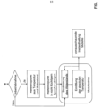
- Es gibt nun verschiedene Möglichkeiten, die Lehre der vorliegenden Erfindung in vorteilhafter Weise auszugestalten und weiterzubilden. Dazu ist einerseits auf die dem Anspruch 1 nachgeordneten Ansprüche und andererseits auf die nachfolgende Erläuterung eines bevorzugten Ausführungsbeispiels der Erfindung anhand der Zeichnung zu verweisen. In Verbindung mit der Erläuterung des bevorzugten Ausführungsbeispiels der Erfindung anhand der Zeichnung werden auch im Allgemeinen bevorzugte Ausgestaltungen und Weiterbildungen der Lehre erläutert. In der Zeichnung zeigt
die einzige Figur in einem schematischen Ablaufdiagramm den grundsätzlichen Ablauf des erfindungsgemäßen Verfahrens zur Nutzung im Rahmen einer vorausschauenden Instandhaltung. - Gemäß der einzigen Figur wird vorausgesetzt, dass der zuvor erörterte Referenzpunkt, umfassend die Wicklungstemperatur und den Wicklungswiderstand vor einer ersten Inbetriebnahme, ermittelt worden ist. Der Referenzpunkt ist/wird in einem nicht flüchtigen Speicher abgelegt, beispielsweise in einem Speicher der MCU.
- Während des Motorbetriebs wird auf herkömmliche Wiese der Wicklungswiderstand ermittelt, beispielsweise über ein sog. Injektionsverfahren mittels Testimpulsen oder über sogenannte Parameterschätzer. Es lässt sich entsprechend den voranstehenden Ausführungen im allgemeinen Teil der Beschreibung die aktuelle absolute Wicklungstemperatur ermitteln. Dieser Wert lässt sich beispielsweise zur vorausschauenden Instandhaltung (Predictive Maintenance) nutzen und kann einem entsprechenden Modell zugeführt werden.
Claims (8)
- Verfahren zur Ermittlung der Wicklungstemperatur eines einen Mikrocontroller (MCU) umfassenden Elektromotors, insbesondere eines Permanentmagnet- Synchronmotors (PMSM), vorzugsweise als Antrieb für einen Ventilator, wobei die Wicklungstemperatur mithilfe bekannter oder ermittelbarer Parameter des Elektromotors unter Zugrundelegung eines Referenzpunktes aus einer Referenztemperatur und einem Wicklungswiderstand bei der Referenztemperatur ermittelt wird,
dadurch gekennzeichnet, dass vorausgesetzt wird, dass vor einer ersten Inbetriebnahme die Wicklungstemperatur der Umgebungstemperatur der Fertigung entspricht, wobei die Temperatur aus einer Temperaturmessung an dem Mikrocontroller der Wicklungstemperatur in etwa gleichgesetzt wird. - Verfahren nach Anspruch 1, dadurch gekennzeichnet, dass die Temperatur aus einer kalibrierten Temperaturmessung an dem Mikrocontroller der Wicklungstemperatur in etwa gleichgesetzt wird.
- Verfahren nach Anspruch 1 oder 2, dadurch gekennzeichnet, dass der Wicklungswiderstand vorzugsweise über Testverfahren oder mathematische Modelle bestimmt wird, wobei das Wertepaar aus Wicklungswiderstand und Wicklungstemperatur (= Umgebungstemperatur in der Fertigung, die mit Hilfe des MCU gemessen wird) als Referenzpunkt für die Bestimmung der Wicklungstemperatur im Betrieb des Elektromotors dient.
- Verfahren nach Anspruch 3, dadurch gekennzeichnet, dass der Wicklungswiderstand, beispielsweise über ein Injektionsverfahren, ermittelt wird, wonach elektrische Impulse auf die Wicklung gegeben werden.
- Verfahren nach Anspruch 3 oder 4, dadurch gekennzeichnet, dass der Referenzpunkt in einem externen Speicher oder einem nicht flüchtigen Speicher des Mikrocontrollers abgelegt wird, wobei ein Abgleich des Wicklungswiderstands mit der Temperatur eines auf der Platine befindlichen Temperatursensors und somit der Wicklungstemperatur lediglich einmal in der Produktion vorgenommen wird, um den Referenzpunkt zu definieren.
- Verfahren nach Anspruch 5,
dadurch gekennzeichnet, dass während des Betriebs des Elektromotors, beispielsweise zyklisch, vorzugsweise mit dem gleichen Verfahren wie vor der ersten Inbetriebnahme, der Wicklungswiderstand ermittelt wird, wobei die Temperaturerhöhung der Wicklung über die Änderung des Wicklungswiderstands wie folgt berechnet wird: Δϑ die Temperaturerhöhung der Wicklung gegenüber der Referenztemperatur,R der aktuelle Wicklungswiderstand,RRef der Wicklungswiderstand vor Inbetriebnahme undα der materialspezifische Temperaturkoeffizient des Wicklungsmaterials, wobei mithilfe des Referenzpunktes und unter Zugrundelegung des berechneten Temperaturanstiegs die aktuelle absolute Wicklungstemperatur ermittelt wird.
 - Verfahren nach einem der Ansprüche 1 bis 6, dadurch gekennzeichnet, dass die aktuelle Wicklungstemperatur als Parameter für sicherheitstechnische Funktionen genutzt wird, um den Elektromotor in kritischen Betriebspunkten vor Überhitzung zu schützen.
- Verfahren nach einem der Ansprüche 1 bis 7, dadurch gekennzeichnet, dass die aktuelle Wicklungstemperatur als Parameter im Rahmen der vorausschauenden Instandhaltung (Predictive Maintenance) genutzt wird, beispielsweise um Aufschluss über das Betriebsverhalten des Elektromotors zu erhalten und um mögliche Schäden oder Ausfälle des Elektromotors aufgrund thermischer Belastung abschätzen bzw. vorhersagen zu können.
Priority Applications (1)
| Application Number | Priority Date | Filing Date | Title |
|---|---|---|---|
| SI202230135T SI4179622T1 (sl) | 2021-07-06 | 2022-06-09 | Postopek za določanje temperature navitja elektromotorja |
Applications Claiming Priority (2)
| Application Number | Priority Date | Filing Date | Title |
|---|---|---|---|
| DE102021207107.4A DE102021207107A1 (de) | 2021-07-06 | 2021-07-06 | Verfahren zur Ermittlung der Wicklungstemperatur eines Elektromotors |
| PCT/DE2022/200115 WO2023280353A1 (de) | 2021-07-06 | 2022-06-09 | Verfahren zur ermittlung der wicklungstemperatur eines elektromotors |
Publications (2)
| Publication Number | Publication Date |
|---|---|
| EP4179622A1 EP4179622A1 (de) | 2023-05-17 |
| EP4179622B1 true EP4179622B1 (de) | 2025-04-02 |
Family
ID=82403969
Family Applications (1)
| Application Number | Title | Priority Date | Filing Date |
|---|---|---|---|
| EP22737735.5A Active EP4179622B1 (de) | 2021-07-06 | 2022-06-09 | Verfahren zur ermittlung der wicklungstemperatur eines elektromotors |
Country Status (5)
| Country | Link |
|---|---|
| EP (1) | EP4179622B1 (de) |
| DE (1) | DE102021207107A1 (de) |
| ES (1) | ES3032307T3 (de) |
| SI (1) | SI4179622T1 (de) |
| WO (1) | WO2023280353A1 (de) |
Families Citing this family (1)
| Publication number | Priority date | Publication date | Assignee | Title |
|---|---|---|---|---|
| EP3961837A1 (de) * | 2020-08-31 | 2022-03-02 | Siemens Aktiengesellschaft | Verfahren zur überwachung einer wicklungstemperatur |
Family Cites Families (6)
| Publication number | Priority date | Publication date | Assignee | Title |
|---|---|---|---|---|
| DE10119201A1 (de) * | 2001-04-19 | 2002-10-24 | Bsh Bosch Siemens Hausgeraete | Verfahren und Vorrichtung zum Messen der Wicklungstemperatur eines Antriebsmotors |
| DE102010063950A1 (de) | 2010-12-22 | 2012-06-28 | BSH Bosch und Siemens Hausgeräte GmbH | Haushaltsgerät mit einem Antriebsmotor und Verfahren zum Betreiben eines solchen Haushaltsgerät |
| DE102014005706B4 (de) * | 2014-04-22 | 2023-02-02 | Diehl Ako Stiftung & Co. Kg | Verfahren und Vorrichtung zum Betreiben eines Elektromotors |
| ES2833799T3 (es) * | 2017-06-29 | 2021-06-15 | Bombardier Transp Gmbh | Procedimiento para detectar diferencias de carga |
| WO2019149326A1 (de) * | 2018-02-05 | 2019-08-08 | Ziehl-Abegg Se | Verfahren zum optimierten betrieb eines ventilators oder einer ventilator-anordnung |
| JP7388158B2 (ja) * | 2019-11-29 | 2023-11-29 | オムロン株式会社 | 処理装置、及び巻線温度算出モデルの決定方法 |
-
2021
- 2021-07-06 DE DE102021207107.4A patent/DE102021207107A1/de active Pending
-
2022
- 2022-06-09 SI SI202230135T patent/SI4179622T1/sl unknown
- 2022-06-09 EP EP22737735.5A patent/EP4179622B1/de active Active
- 2022-06-09 WO PCT/DE2022/200115 patent/WO2023280353A1/de not_active Ceased
- 2022-06-09 ES ES22737735T patent/ES3032307T3/es active Active
Also Published As
| Publication number | Publication date |
|---|---|
| EP4179622A1 (de) | 2023-05-17 |
| SI4179622T1 (sl) | 2025-07-31 |
| DE102021207107A1 (de) | 2023-01-12 |
| WO2023280353A1 (de) | 2023-01-12 |
| ES3032307T3 (en) | 2025-07-17 |
Similar Documents
| Publication | Publication Date | Title |
|---|---|---|
| DE19729238C1 (de) | Verfahren zum Ermitteln der Drehzahl bei mechanisch kommutierten Gleichstrommotoren | |
| DE112015001924B4 (de) | Motorsteuereinrichtung | |
| DE3818722C2 (de) | ||
| DE102010043358A1 (de) | Verfahren und Systeme zur Thermistortemperaturverarbeitung | |
| EP3454071B1 (de) | Verfahren zur überwachung der funktion eines kühlsystems einer magnetresonanzeinrichtung, magnetresonanzeinrichtung, computerprogramm und elektronisch lesbarer datenträger | |
| DE3519840C2 (de) | ||
| DE10002473A1 (de) | Verfahren zur Bestimmung des Ladezusatandes von Akkumulatoren | |
| DE102014015230A1 (de) | Steuervorrichtung zum automatischen Starten eines Warmlaufens | |
| DE102016008283B4 (de) | Motorantriebsvorrichtung umfassend einen widerstandsbremskreis | |
| DE102014005706B4 (de) | Verfahren und Vorrichtung zum Betreiben eines Elektromotors | |
| DE112020005865B4 (de) | Verarbeitungseinrichtung und Verfahren zur Bestimmung eines Modells zur Berechnung von Wicklungstemperaturen | |
| DE102017100881A1 (de) | Wicklungstemperaturüberwachung | |
| EP2725331B1 (de) | Verfahren und Vorrichtung zum Bestimmen einer Betriebstemperatur eines Elektromotors | |
| DE3632671A1 (de) | Vorrichtung zur temperaturueberwachung eines gleichstromnebenschlussmotors zum antrieb von rotationsdruckmaschinen | |
| DE102021207107A1 (de) | Verfahren zur Ermittlung der Wicklungstemperatur eines Elektromotors | |
| DE102022120965A1 (de) | Verfahren zum vorhersagen der rotortemperatur für einen elektromotor | |
| EP2484004B1 (de) | Verfahren zum schutz eines kraftfahrzeuggenerators vor einer überhitzung | |
| DE102017007303A1 (de) | Motorsteuervorrichtung, steuerverfahren und steuerprogramm zur spezifizierung eines typs von temperatursensor | |
| DE102014210645A1 (de) | Verfahren und System zur Temperaturbestimmung in einer Antriebseinheit | |
| WO2023110205A1 (de) | Verfahren und vorrichtung zum plausibilisieren einer temperatur in einer komponente einer elektrischen maschine in einem technischen system | |
| DE3910643A1 (de) | Verfahren zur serienmaessigen leistungspruefung von gleichstrom-kleinmotoren mit permanentmagneten | |
| DE102022200785A1 (de) | Vorrichtung und Verfahren zur Diagnose eines Batteriefehlers | |
| DE102009032432B3 (de) | Ermittlung einer Motortemperatur | |
| DE102019125926A1 (de) | Verfahren zum Betrieb einer elektrischen Maschine, elektrische Maschine, Kraftfahrzeug, Verfahren zum Betrieb eines Kraftfahrzeugs | |
| DE102004042403B4 (de) | Verfahren zur Steuerung des in einer Stromstrecke mit einem Elektromotor, einer Steuerschaltung und Anschlusselementen fließenden Stroms |
Legal Events
| Date | Code | Title | Description |
|---|---|---|---|
| STAA | Information on the status of an ep patent application or granted ep patent |
Free format text: STATUS: UNKNOWN |
|
| STAA | Information on the status of an ep patent application or granted ep patent |
Free format text: STATUS: THE INTERNATIONAL PUBLICATION HAS BEEN MADE |
|
| PUAI | Public reference made under article 153(3) epc to a published international application that has entered the european phase |
Free format text: ORIGINAL CODE: 0009012 |
|
| STAA | Information on the status of an ep patent application or granted ep patent |
Free format text: STATUS: REQUEST FOR EXAMINATION WAS MADE |
|
| 17P | Request for examination filed |
Effective date: 20230208 |
|
| AK | Designated contracting states |
Kind code of ref document: A1 Designated state(s): AL AT BE BG CH CY CZ DE DK EE ES FI FR GB GR HR HU IE IS IT LI LT LU LV MC MK MT NL NO PL PT RO RS SE SI SK SM TR |
|
| DAV | Request for validation of the european patent (deleted) | ||
| DAX | Request for extension of the european patent (deleted) | ||
| GRAP | Despatch of communication of intention to grant a patent |
Free format text: ORIGINAL CODE: EPIDOSNIGR1 |
|
| STAA | Information on the status of an ep patent application or granted ep patent |
Free format text: STATUS: GRANT OF PATENT IS INTENDED |
|
| INTG | Intention to grant announced |
Effective date: 20241112 |
|
| P01 | Opt-out of the competence of the unified patent court (upc) registered |
Free format text: CASE NUMBER: APP_65263/2024 Effective date: 20241210 |
|
| GRAS | Grant fee paid |
Free format text: ORIGINAL CODE: EPIDOSNIGR3 |
|
| GRAA | (expected) grant |
Free format text: ORIGINAL CODE: 0009210 |
|
| STAA | Information on the status of an ep patent application or granted ep patent |
Free format text: STATUS: THE PATENT HAS BEEN GRANTED |
|
| AK | Designated contracting states |
Kind code of ref document: B1 Designated state(s): AL AT BE BG CH CY CZ DE DK EE ES FI FR GB GR HR HU IE IS IT LI LT LU LV MC MK MT NL NO PL PT RO RS SE SI SK SM TR |
|
| REG | Reference to a national code |
Ref country code: GB Ref legal event code: FG4D Free format text: NOT ENGLISH |
|
| REG | Reference to a national code |
Ref country code: CH Ref legal event code: EP |
|
| REG | Reference to a national code |
Ref country code: DE Ref legal event code: R096 Ref document number: 502022003456 Country of ref document: DE |
|
| REG | Reference to a national code |
Ref country code: IE Ref legal event code: FG4D Free format text: LANGUAGE OF EP DOCUMENT: GERMAN |
|
| REG | Reference to a national code |
Ref country code: ES Ref legal event code: FG2A Ref document number: 3032307 Country of ref document: ES Kind code of ref document: T3 Effective date: 20250717 |
|
| PGFP | Annual fee paid to national office [announced via postgrant information from national office to epo] |
Ref country code: FR Payment date: 20250626 Year of fee payment: 4 |
|
| PGFP | Annual fee paid to national office [announced via postgrant information from national office to epo] |
Ref country code: AT Payment date: 20250721 Year of fee payment: 4 |
|
| PGFP | Annual fee paid to national office [announced via postgrant information from national office to epo] |
Ref country code: SI Payment date: 20250602 Year of fee payment: 4 |
|
| REG | Reference to a national code |
Ref country code: NL Ref legal event code: MP Effective date: 20250402 |
|
| PG25 | Lapsed in a contracting state [announced via postgrant information from national office to epo] |
Ref country code: NL Free format text: LAPSE BECAUSE OF FAILURE TO SUBMIT A TRANSLATION OF THE DESCRIPTION OR TO PAY THE FEE WITHIN THE PRESCRIBED TIME-LIMIT Effective date: 20250402 |
|
| PG25 | Lapsed in a contracting state [announced via postgrant information from national office to epo] |
Ref country code: FI Free format text: LAPSE BECAUSE OF FAILURE TO SUBMIT A TRANSLATION OF THE DESCRIPTION OR TO PAY THE FEE WITHIN THE PRESCRIBED TIME-LIMIT Effective date: 20250402 Ref country code: PT Free format text: LAPSE BECAUSE OF FAILURE TO SUBMIT A TRANSLATION OF THE DESCRIPTION OR TO PAY THE FEE WITHIN THE PRESCRIBED TIME-LIMIT Effective date: 20250804 |
|
| PGFP | Annual fee paid to national office [announced via postgrant information from national office to epo] |
Ref country code: ES Payment date: 20250718 Year of fee payment: 4 |
|
| PGFP | Annual fee paid to national office [announced via postgrant information from national office to epo] |
Ref country code: DE Payment date: 20250829 Year of fee payment: 4 |
|
| REG | Reference to a national code |
Ref country code: LT Ref legal event code: MG9D |
|
| PG25 | Lapsed in a contracting state [announced via postgrant information from national office to epo] |
Ref country code: GR Free format text: LAPSE BECAUSE OF FAILURE TO SUBMIT A TRANSLATION OF THE DESCRIPTION OR TO PAY THE FEE WITHIN THE PRESCRIBED TIME-LIMIT Effective date: 20250703 Ref country code: NO Free format text: LAPSE BECAUSE OF FAILURE TO SUBMIT A TRANSLATION OF THE DESCRIPTION OR TO PAY THE FEE WITHIN THE PRESCRIBED TIME-LIMIT Effective date: 20250702 |
|
| PG25 | Lapsed in a contracting state [announced via postgrant information from national office to epo] |
Ref country code: PL Free format text: LAPSE BECAUSE OF FAILURE TO SUBMIT A TRANSLATION OF THE DESCRIPTION OR TO PAY THE FEE WITHIN THE PRESCRIBED TIME-LIMIT Effective date: 20250402 |
|
| PGFP | Annual fee paid to national office [announced via postgrant information from national office to epo] |
Ref country code: IT Payment date: 20250630 Year of fee payment: 4 |
|
| PG25 | Lapsed in a contracting state [announced via postgrant information from national office to epo] |
Ref country code: BG Free format text: LAPSE BECAUSE OF FAILURE TO SUBMIT A TRANSLATION OF THE DESCRIPTION OR TO PAY THE FEE WITHIN THE PRESCRIBED TIME-LIMIT Effective date: 20250402 |
|
| PG25 | Lapsed in a contracting state [announced via postgrant information from national office to epo] |
Ref country code: HR Free format text: LAPSE BECAUSE OF FAILURE TO SUBMIT A TRANSLATION OF THE DESCRIPTION OR TO PAY THE FEE WITHIN THE PRESCRIBED TIME-LIMIT Effective date: 20250402 |
|
| PG25 | Lapsed in a contracting state [announced via postgrant information from national office to epo] |
Ref country code: RS Free format text: LAPSE BECAUSE OF FAILURE TO SUBMIT A TRANSLATION OF THE DESCRIPTION OR TO PAY THE FEE WITHIN THE PRESCRIBED TIME-LIMIT Effective date: 20250702 |
|
| PG25 | Lapsed in a contracting state [announced via postgrant information from national office to epo] |
Ref country code: IS Free format text: LAPSE BECAUSE OF FAILURE TO SUBMIT A TRANSLATION OF THE DESCRIPTION OR TO PAY THE FEE WITHIN THE PRESCRIBED TIME-LIMIT Effective date: 20250802 |
|
| PG25 | Lapsed in a contracting state [announced via postgrant information from national office to epo] |
Ref country code: LV Free format text: LAPSE BECAUSE OF FAILURE TO SUBMIT A TRANSLATION OF THE DESCRIPTION OR TO PAY THE FEE WITHIN THE PRESCRIBED TIME-LIMIT Effective date: 20250402 |
|
| REG | Reference to a national code |
Ref country code: DE Ref legal event code: R097 Ref document number: 502022003456 Country of ref document: DE |
|
| PG25 | Lapsed in a contracting state [announced via postgrant information from national office to epo] |
Ref country code: SM Free format text: LAPSE BECAUSE OF FAILURE TO SUBMIT A TRANSLATION OF THE DESCRIPTION OR TO PAY THE FEE WITHIN THE PRESCRIBED TIME-LIMIT Effective date: 20250402 Ref country code: DK Free format text: LAPSE BECAUSE OF FAILURE TO SUBMIT A TRANSLATION OF THE DESCRIPTION OR TO PAY THE FEE WITHIN THE PRESCRIBED TIME-LIMIT Effective date: 20250402 |
|
| PG25 | Lapsed in a contracting state [announced via postgrant information from national office to epo] |
Ref country code: CZ Free format text: LAPSE BECAUSE OF FAILURE TO SUBMIT A TRANSLATION OF THE DESCRIPTION OR TO PAY THE FEE WITHIN THE PRESCRIBED TIME-LIMIT Effective date: 20250402 |
|
| PG25 | Lapsed in a contracting state [announced via postgrant information from national office to epo] |
Ref country code: EE Free format text: LAPSE BECAUSE OF FAILURE TO SUBMIT A TRANSLATION OF THE DESCRIPTION OR TO PAY THE FEE WITHIN THE PRESCRIBED TIME-LIMIT Effective date: 20250402 |
|
| PG25 | Lapsed in a contracting state [announced via postgrant information from national office to epo] |
Ref country code: SK Free format text: LAPSE BECAUSE OF FAILURE TO SUBMIT A TRANSLATION OF THE DESCRIPTION OR TO PAY THE FEE WITHIN THE PRESCRIBED TIME-LIMIT Effective date: 20250402 |
|
| REG | Reference to a national code |
Ref country code: CH Ref legal event code: H13 Free format text: ST27 STATUS EVENT CODE: U-0-0-H10-H13 (AS PROVIDED BY THE NATIONAL OFFICE) Effective date: 20260127 |
|
| PG25 | Lapsed in a contracting state [announced via postgrant information from national office to epo] |
Ref country code: MC Free format text: LAPSE BECAUSE OF FAILURE TO SUBMIT A TRANSLATION OF THE DESCRIPTION OR TO PAY THE FEE WITHIN THE PRESCRIBED TIME-LIMIT Effective date: 20250402 |
|
| PLBE | No opposition filed within time limit |
Free format text: ORIGINAL CODE: 0009261 |
|
| STAA | Information on the status of an ep patent application or granted ep patent |
Free format text: STATUS: NO OPPOSITION FILED WITHIN TIME LIMIT |
|
| REG | Reference to a national code |
Ref country code: CH Ref legal event code: L10 Free format text: ST27 STATUS EVENT CODE: U-0-0-L10-L00 (AS PROVIDED BY THE NATIONAL OFFICE) Effective date: 20260211 |
|
| PG25 | Lapsed in a contracting state [announced via postgrant information from national office to epo] |
Ref country code: LU Free format text: LAPSE BECAUSE OF NON-PAYMENT OF DUE FEES Effective date: 20250609 |
|
| REG | Reference to a national code |
Ref country code: BE Ref legal event code: MM Effective date: 20250630 |
|
| PG25 | Lapsed in a contracting state [announced via postgrant information from national office to epo] |
Ref country code: RO Free format text: LAPSE BECAUSE OF FAILURE TO SUBMIT A TRANSLATION OF THE DESCRIPTION OR TO PAY THE FEE WITHIN THE PRESCRIBED TIME-LIMIT Effective date: 20250402 |
|
| 26N | No opposition filed |
Effective date: 20260105 |
|
| PG25 | Lapsed in a contracting state [announced via postgrant information from national office to epo] |
Ref country code: IE Free format text: LAPSE BECAUSE OF NON-PAYMENT OF DUE FEES Effective date: 20250609 |
|
| PG25 | Lapsed in a contracting state [announced via postgrant information from national office to epo] |
Ref country code: BE Free format text: LAPSE BECAUSE OF NON-PAYMENT OF DUE FEES Effective date: 20250630 |
|
| PG25 | Lapsed in a contracting state [announced via postgrant information from national office to epo] |
Ref country code: CH Free format text: LAPSE BECAUSE OF NON-PAYMENT OF DUE FEES Effective date: 20250630 |