EP4179529B1 - Audiodecodierer, audiocodierer und zugehörige verfahren mit gemeinsamer codierung von skalenparametern für kanäle eines mehrkanalaudiosignals - Google Patents
Audiodecodierer, audiocodierer und zugehörige verfahren mit gemeinsamer codierung von skalenparametern für kanäle eines mehrkanalaudiosignals Download PDFInfo
- Publication number
- EP4179529B1 EP4179529B1 EP21742333.4A EP21742333A EP4179529B1 EP 4179529 B1 EP4179529 B1 EP 4179529B1 EP 21742333 A EP21742333 A EP 21742333A EP 4179529 B1 EP4179529 B1 EP 4179529B1
- Authority
- EP
- European Patent Office
- Prior art keywords
- scale
- scale parameters
- channel
- parameters
- group
- Prior art date
- Legal status (The legal status is an assumption and is not a legal conclusion. Google has not performed a legal analysis and makes no representation as to the accuracy of the status listed.)
- Active
Links
Images


Classifications
-
- G—PHYSICS
- G10—MUSICAL INSTRUMENTS; ACOUSTICS
- G10L—SPEECH ANALYSIS TECHNIQUES OR SPEECH SYNTHESIS; SPEECH RECOGNITION; SPEECH OR VOICE PROCESSING TECHNIQUES; SPEECH OR AUDIO CODING OR DECODING
- G10L19/00—Speech or audio signals analysis-synthesis techniques for redundancy reduction, e.g. in vocoders; Coding or decoding of speech or audio signals, using source filter models or psychoacoustic analysis
- G10L19/008—Multichannel audio signal coding or decoding using interchannel correlation to reduce redundancy, e.g. joint-stereo, intensity-coding or matrixing
-
- G—PHYSICS
- G06—COMPUTING OR CALCULATING; COUNTING
- G06F—ELECTRIC DIGITAL DATA PROCESSING
- G06F3/00—Input arrangements for transferring data to be processed into a form capable of being handled by the computer; Output arrangements for transferring data from processing unit to output unit, e.g. interface arrangements
- G06F3/16—Sound input; Sound output
- G06F3/162—Interface to dedicated audio devices, e.g. audio drivers, interface to CODECs
-
- G—PHYSICS
- G10—MUSICAL INSTRUMENTS; ACOUSTICS
- G10L—SPEECH ANALYSIS TECHNIQUES OR SPEECH SYNTHESIS; SPEECH RECOGNITION; SPEECH OR VOICE PROCESSING TECHNIQUES; SPEECH OR AUDIO CODING OR DECODING
- G10L19/00—Speech or audio signals analysis-synthesis techniques for redundancy reduction, e.g. in vocoders; Coding or decoding of speech or audio signals, using source filter models or psychoacoustic analysis
- G10L19/002—Dynamic bit allocation
-
- G—PHYSICS
- G10—MUSICAL INSTRUMENTS; ACOUSTICS
- G10L—SPEECH ANALYSIS TECHNIQUES OR SPEECH SYNTHESIS; SPEECH RECOGNITION; SPEECH OR VOICE PROCESSING TECHNIQUES; SPEECH OR AUDIO CODING OR DECODING
- G10L19/00—Speech or audio signals analysis-synthesis techniques for redundancy reduction, e.g. in vocoders; Coding or decoding of speech or audio signals, using source filter models or psychoacoustic analysis
- G10L19/02—Speech or audio signals analysis-synthesis techniques for redundancy reduction, e.g. in vocoders; Coding or decoding of speech or audio signals, using source filter models or psychoacoustic analysis using spectral analysis, e.g. transform vocoders or subband vocoders
- G10L19/032—Quantisation or dequantisation of spectral components
- G10L19/035—Scalar quantisation
-
- G—PHYSICS
- G10—MUSICAL INSTRUMENTS; ACOUSTICS
- G10L—SPEECH ANALYSIS TECHNIQUES OR SPEECH SYNTHESIS; SPEECH RECOGNITION; SPEECH OR VOICE PROCESSING TECHNIQUES; SPEECH OR AUDIO CODING OR DECODING
- G10L19/00—Speech or audio signals analysis-synthesis techniques for redundancy reduction, e.g. in vocoders; Coding or decoding of speech or audio signals, using source filter models or psychoacoustic analysis
- G10L19/02—Speech or audio signals analysis-synthesis techniques for redundancy reduction, e.g. in vocoders; Coding or decoding of speech or audio signals, using source filter models or psychoacoustic analysis using spectral analysis, e.g. transform vocoders or subband vocoders
- G10L19/032—Quantisation or dequantisation of spectral components
- G10L19/038—Vector quantisation, e.g. TwinVQ audio
-
- G—PHYSICS
- G10—MUSICAL INSTRUMENTS; ACOUSTICS
- G10L—SPEECH ANALYSIS TECHNIQUES OR SPEECH SYNTHESIS; SPEECH RECOGNITION; SPEECH OR VOICE PROCESSING TECHNIQUES; SPEECH OR AUDIO CODING OR DECODING
- G10L19/00—Speech or audio signals analysis-synthesis techniques for redundancy reduction, e.g. in vocoders; Coding or decoding of speech or audio signals, using source filter models or psychoacoustic analysis
- G10L19/04—Speech or audio signals analysis-synthesis techniques for redundancy reduction, e.g. in vocoders; Coding or decoding of speech or audio signals, using source filter models or psychoacoustic analysis using predictive techniques
- G10L19/16—Vocoder architecture
- G10L19/18—Vocoders using multiple modes
- G10L19/22—Mode decision, i.e. based on audio signal content versus external parameters
-
- H—ELECTRICITY
- H04—ELECTRIC COMMUNICATION TECHNIQUE
- H04S—STEREOPHONIC SYSTEMS
- H04S7/00—Indicating arrangements; Control arrangements, e.g. balance control
- H04S7/30—Control circuits for electronic adaptation of the sound field
- H04S7/307—Frequency adjustment, e.g. tone control
-
- G—PHYSICS
- G10—MUSICAL INSTRUMENTS; ACOUSTICS
- G10L—SPEECH ANALYSIS TECHNIQUES OR SPEECH SYNTHESIS; SPEECH RECOGNITION; SPEECH OR VOICE PROCESSING TECHNIQUES; SPEECH OR AUDIO CODING OR DECODING
- G10L19/00—Speech or audio signals analysis-synthesis techniques for redundancy reduction, e.g. in vocoders; Coding or decoding of speech or audio signals, using source filter models or psychoacoustic analysis
- G10L2019/0001—Codebooks
- G10L2019/0004—Design or structure of the codebook
- G10L2019/0005—Multi-stage vector quantisation
Definitions
- the present invention is related to audio signal processing an can e.g. be applied in an MDCT-stereo processing of e.g. IVAS.
- the present invention can be applied in Joint Coding of the Stereo Spectral Noise Shaping Parameters Spectral noise shaping shapes the quantization noise in the frequency domain such that the quantization noise is minimally perceived by the human ear and therefore, the perceptual quality of the decoded output signal can be maximized.
- Spectral noise shaping is a technique used in most state-of-the-art transform-based audio codecs.
- AAC Advanced Audio Coding
- the MDCT spectrum is partitioned into a number of non-uniform scale factor bands. For example, at 48kHz, the MDCT has 1024 coefficients and it is partitioned into 49 scale factor bands. In each band, a scale factor is used to scale the MDCT coefficients of that band. A scalar quantizer with constant step size is then employed to quantize the scaled MDCT coefficients. At the decoder-side, inverse scaling is performed in each band, shaping the quantization noise introduced by the scalar quantizer.
- the 49 scale factors are encoded into the bitstream as side-information. It usually requires a significantly high number of bits for encoding the scale factors, due to the relatively high number of scale factors and the required high precision. This can become a problem at low bitrate and/or at low delay.
- spectral noise shaping is performed with the help of an LPC-based perceptual filters, similar perceptual filter as used in recent ACELP- based speech codecs (e.g. AMR-WB).
- LPCs Linear Prediction Coefficients
- the LPCs are then weighted and quantized.
- the frequency response of the weighted and quantized LPCs is then computed in 64 uniformly spaced bands.
- the MDCT coefficients are then scaled in each band using the computed frequency response.
- the scaled MDCT coefficients are then quantized using a scalar quantizer with a step size controlled by a global gain.
- inverse scaling is performed in every 64 bands, shaping the quantization noise introduced by the scalar quantizer.
- preprocessing of the discrete L R channel signals is performed in order to scale the spectra using frequency domain noise-shaping to the "whitened domain”. Then, joint stereo processing is performed to quantize and code the whitened spectra in an optimal fashion.
- the scaling parameters for the spectral noise shaping techniques described before are quantized encoded independently for each channel. This results in a double bitrate of side information needed to be sent to the decoder through the bitstream.
- US 2007/016427 A1 discloses techniques and tools for representing, coding, and decoding scale factor information.
- an encoder uses one or more of flexible scale factor resolution selection, spatial prediction of scale factors, flexible prediction of scale factors, smoothing of noisy scale factor amplitudes, reordering of scale factor prediction residuals, and prediction of scale factor prediction residuals.
- a decoder uses one or more of flexible scale factor resolution selection, spatial prediction of scale factors, flexible prediction of scale factors, reordering of scale factor prediction residuals, and prediction of scale factor prediction residuals.
- an audio decoder of claim 1 an audio encoder of claim 17, a method of decoding of claim 35, a method of encoding of claim 36, or a computer program of claim 37.
- the present invention is based on the finding that bitrate savings can be obtained for cases, where the L, R signals or, generally, two or more channels of a multi-channel signal are correlated. In such a case, the extracted parameters for both channels are rather similar.
- bitrate can be used in several different directions.
- One direction can be to spend the saved bitrate on the coding of the core signal so that the overall perceptual quality of the stereo or multichannel signal is improved.
- Another direction is to reach a lower overall bitrate in a case where the coding of the core signal and, therefore, the overall perceptual quality is not improved, but is left at the same quality.
- independent claim 17 defines, in accordance with a first aspect, an audio encoder for encoding a multi-channel audio signal comprising two or more channels, comprising a scale parameter calculator for calculating a first group of jointly encoded scale parameters and a second group of jointly encoded scale parameters for a first set of scale parameters for a first channel of the multi-channel audio signal and for a second set of scale parameters for a second channel of the multi-channel audio signal.
- the audio encoder additionally comprises a signal processor for applying the first set of scale parameters to the first channel and for applying the second set of scale parameters to the second channel of the multi-channel audio signal.
- the signal processor additionally derives multi-channel audio data from the first and second channel data obtained by the application of the first and second sets of scale parameters, respectively.
- the audio encoder additionally has an encoded signal former for using the multi-channel audio data and the information on the first group of jointly encoded scale parameters and the information on the second group of jointly encoded scale parameters to obtain an encoded multi-channel audio signal.
- the scale parameter calculator is configured to be adaptive so that, for each frame or sub-frame of the multi-channel audio signal, a determination is made, whether jointly encoding scale parameters or separately encoding scale parameters is to be performed. In a further embodiment, this determination is based on a similarity analysis between the channels of the multi-channel audio signal under consideration. Particularly, the similarity analysis is done by calculating an energy of the jointly encoded parameters and, particularly, an energy of one set of scale parameters from the first group and the second group of jointly encoded scale parameters. Particularly, the scale parameter calculator calculates the first group as a sum between corresponding first and second scale parameters and calculates the second group as a difference between the first and second corresponding scale parameters.
- the second group and, preferably, the scale parameters that represent the difference are used for the determination of the similarity measure in order to decide, whether jointly encoding the scale parameters or separately encoding the scale parameters is to be performed.
- This situation can be signaled via a stereo or multi-channel flag.
- a first stage vector quantizer quantizes the plurality of scale parameters or, generally, audio information items to determination a first stage vector quantization result and to determinate a plurality of intermediate quantizer items corresponding to the first stage vector quantization result.
- the quantizer comprises a residual item determiner for calculating a plurality of residual items from the plurality of intermediate quantized items and the plurality of audio information items.
- a second stage vector quantizer is provided for quantizing the plurality of residual items to obtain a second stage vector quantization result, wherein the first stage vector quantization result and the second stage vector quantization result together represent the quantized representation of the plurality of audio information items which are, in one embodiment, the scale parameters.
- the audio information items can either be jointly encoded scale parameters or separately encoded scale parameters.
- other audio information items can be any audio information items that are useful for vector quantization.
- other audio information items useful for the vector-quantized are spectral values such as MDCT or FFT lines.
- spectral values such as MDCT or FFT lines.
- time domain audio values such as audio sampling values or groups of time domain audio samples or groups of spectral domain frequency lines or LPC data or other envelope data be it a spectral or a time envelope data representation.
- the residual item determiner calculates, for each residual item, a difference between corresponding audio information items such as a scale parameter and a corresponding intermediate quantized item such as a quantized scale parameter or scale factor. Furthermore, the residual item determiner is configured to amplify or weight, for each residual item, a difference between a corresponding audio information item and a corresponding intermediate quantized item so that the plurality of residual items are greater than the corresponding difference or to amplify or weigh the plurality of audio information items and/or the plurality of intermediate quantized items before calculating a difference between the amplified items to obtain the residual items.
- a useful control of the quantization error can be made. Particularly, when the second group of audio information items such as the different scale parameters are quite small, which is typically the case, when the first and the second channels are correlated to each other so that joint quantization has been determined, the residual items are typically quite small.
- the result of the quantization will comprise more values that are not quantized to 0 compared to a case, where this amplification has not been performed. Therefore, an amplification on the encoder or quantization side may be useful.
- the quantization of the jointly encoded second group of scale parameters is performed. Due to the fact that these side scale parameters are anyway small, a situation may arise that, without the amplification, most of the different scale parameters are quantized to 0 anyway. Therefore, in order to avoid this situation which might result in a loss of stereo impression and, therefore, in a loss of psychoacoustic quality, the amplification is performed so that only a small amount or almost no side scale parameters are quantized to 0. This, of course, reduces the savings in bitrate.
- quantized residual data items are anyway only small, i.e., result in quantization indexes that represent small values and the bitrate increase is not too high, since quantization indexes for small values are encoded more efficiently than quantization indexes for higher values.
- This can even be enhanced by additionally performing an entropy coding operation that even more favors small quantization indexes with respect to bitrate over higher quantization indexes.
- the first stage vector quantizer is a vector quantizer having a certain codebook and the second stage vector quantizer is an algebraic vector quantizer resulting, as a quantization index, in a codebook number, a vector index in a base codebook and a Voronoi index.
- both the vector quantizer and the algebraic vector quantizer are configured to perform a split level vector quantization where both quantizers have the same split level procedure.
- the first and the second stage vector quantizers are configured in such a way that the number of bits and, therefore, the precision of the first stage vector quantizer result is greater than the number of bits or the precision of the second stage vector quantizer result, or the number of bits and, therefore, the precision of the first stage vector quantizer result is different from the number of bits or the precision of the second stage vector quantizer result.
- the first stage vector quantizer has a fixed bitrate and the second stage vector quantizer has a variable bitrate.
- the characteristics of the first stage and the second stage vector quantizers are different from each other.
- independent claim 1 defines an audio decoder for decoding an encoded audio signal comprising multi-channel audio data comprising data for two or more audio channels, and information on jointly encoded scale parameters
- the audio decoder comprises a scale parameter decoder for decoding the information on the jointly encoded scale parameters.
- the audio decoder has a signal processor, where the scale parameter decoder is configured to combine a jointly encoded scale parameter of the first group and the jointly encoded scale parameter of the second group using different combination rules to obtain the scale parameters for the first set of scale parameters and the scale parameters for the second set of scale parameters that are then used by the signal processor.
- an audio dequantizer comprises a first stage vector dequantizer, a second stage vector dequantizer and a combiner for combining the plurality of intermediate quantizer information items obtained by the first stage vector dequantizer and the plurality of residual items obtained from the second stage vector dequantizer to obtain a dequantized plurality of audio information items.
- the first aspect of joint scale parameter coding can be combined with the second aspect related to the two stage vector quantization.
- the aspect of the two stage vector quantization can be applied to separately encoded scale parameters such as scale parameters for a left channel and a right channel or can be applied to the mid-scale parameters as another kind of audio information item.
- the second aspect of two-stage vector quantization can be applied independent from the first aspect or together with the first aspect.
- the scaling parameters that are extracted from any of the techniques described in the introductory section for performing the frequency-domain noise shaping in the encoder side, need to be quantized and coded to be included as side-information to the bitstream. Then in the decoder side, scaling parameters are decoded and used to scale the spectrum of each channel to shape quantization noise in a manner that is minimally perceived.
- Spectral noise shaping scaling parameters are coded adaptively either independently or jointly, depending on the degree of correlation between the two channels.
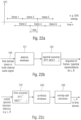
- Fig. 24 an MDCT-stereo based encoder implementation is shown as described in detail in [8].
- An essential part of the stereo system described in [8] is that the stereo processing is performed on the "whitened" spectra. Therefore, each channel undergoes a preprocessing, where for each frame, after windowing, the time domain block is transformed to the MDCT-domain, then Temporal Noise Shaping (TNS) is applied adaptively, either before or after the Spectral Noise Shaping (SNS) depending on the signal characteristics.
- TMS Temporal Noise Shaping
- SNS Spectral Noise Shaping
- joint stereo processing is performed, namely an adaptive band-wise M-S, L/R decision, to quantize and code the whitened spectra coefficients in an efficient manner.
- the block window illustrates a windowing operation.
- the block MCLT stands for modified complex lapped transform.
- the block MDCT stands for modified discrete cosine transform.
- the block power spectrum stands for the calculation of a power spectrum.
- the block block switching decision stands for an analysis of the input signal to determine block lengths to be used for windowing.
- the block TNS stands for temporal noise shaping and this feature is performed either before or after the scaling of the spectrum in the block SNS.
- the encoded signal is decoded and inverse quantization and inverse stereo processing is performed. Then, the spectrum of each channel is "de-whitened" by the spectral noise shaping parameters that are retrieved from the bitstream. Similar reference numbers as in Fig. 1 have been added.
- the decoding and processing of the scale factors takes place in the blocks 220 in Fig. 25 .
- the blocks indicated in the figure are related to the blocks in the encoder in Fig. 24 and typically perform the corresponding inverse operations.
- the block "window and OLA" performs a synthesis windowing operation and a subsequent overlap and add operation to obtain the time domain output signals L and R.
- FDNS frequency-domain noise shaping
- a low bitrate without substantial loss of quality can be obtained by scaling, on the encoder-side, with a higher number of scale factors and by downsampling the scale parameters on the encoder-side into a second set of scale parameters or scale factors, where the scale parameters in the second set that is then encoded and transmitted or stored via an output interface is lower than the first number of scale parameters.
- a fine scaling on the one hand and a low bitrate on the other hand is obtained on the encoder-side.
- the transmitted small number of scale factors is decoded by a scale factor decoder to obtain a first set of scale factors where the number of scale factors or scale parameters in the first set is greater than the number of scale factors or scale parameters of the second set and, then, once again, a fine scaling using the higher number of scale parameters is performed on the decoder-side within a spectral processor to obtain a fine-scaled spectral representation.
- Spectral noise shaping as done in preferred embodiments is implemented using only a very low bitrate. Thus, this spectral noise shaping can be an essential tool even in a low bitrate transform-based audio codec.
- the spectral noise shaping shapes the quantization noise in the frequency domain such that the quantization noise is minimally perceived by the human ear and, therefore, the perceptual quality of the decoded output signal can be maximized.
- Preferred embodiments rely on spectral parameters calculated from amplitude-related measures, such as energies of a spectral representation.
- band-wise energies or, generally, band-wise amplitude-related measures are calculated as the basis for the scale parameters, where the bandwidths used in calculating the band-wise amplitude-related measures increase from lower to higher bands in order to approach the characteristic of the human hearing as far as possible.
- the division of the spectral representation into bands is done in accordance with the well-known Bark scale.
- linear-domain scale parameters are calculated and are particularly calculated for the first set of scale parameters with the high number of scale parameters, and this high number of scale parameters is converted into a log-like domain.
- a log-like domain is generally a domain, in which small values are expanded and high values are compressed. Then, the downsampling or decimation operation of the scale parameters is done in the log-like domain that can be a logarithmic domain with the base 10, or a logarithmic domain with the base 2, where the latter is preferred for implementation purposes.
- the second set of scale factors is then calculated in the log-like domain and, preferably, a vector quantization of the second set of scale factors is performed, wherein the scale factors are in the log-like domain.
- the result of the vector quantization indicates log-like domain scale parameters.
- the second set of scale factors or scale parameters has, for example, a number of scale factors half of the number of scale factors of the first set, or even one third or yet even more preferably, one fourth. Then, the quantized small number of scale parameters in the second set of scale parameters is brought into the bitstream and is then transmitted from the encoder-side to the decoder-side or stored as an encoded audio signal together with a quantized spectrum that has also been processed using these parameters, where this processing additionally involves quantization using a global gain.
- the encoder derives from these quantized log-like domain second scale factors once again a set of linear domain scale factors, which is the third set of scale factors, and the number of scale factors in the third set of scale factors is greater than the second number and is preferably even equal to the first number of scale factors in the first set of first scale factors.
- these interpolated scale factors are used for processing the spectral representation, where the processed spectral representation is finally quantized and, in any way entropy-encoded, such as by Huffman-encoding, arithmetic encoding or vector-quantization-based encoding, etc.
- the low number of scale parameters is interpolated to a high number of scale parameters, i.e., to obtain a first set of scale parameters where a number of scale parameters of the scale factors of the second set of scale factors or scale parameters is smaller than the number of scale parameters of the first set, i.e., the set as calculated by the scale factor/parameter decoder.
- a spectral processor located within the apparatus for decoding an encoded audio signal processes the decoded spectral representation using this first set of scale parameters to obtain a scaled spectral representation.
- a converter for converting the scaled spectral representation then operates to finally obtain a decoded audio signal that is preferably in the time domain.
- spectral noise shaping is performed with the help of 16 scaling parameters similar to the scale factors used in [6] or [8] or [1]. These parameters are obtained in the encoder by first computing the energy of the MDCT spectrum in 64 non-uniform bands (similar to the 64 non-uniform bands of prior art 3), then by applying some processing to the 64 energies (smoothing, pre-emphasis, noise-floor, log-conversion), then by downsampling the 64 processed energies by a factor of 4 to obtain 16 parameters which are finally normalized and scaled. These 16 parameters are then quantized using vector quantization (using similar vector quantization as used in prior art 2/3).
- the quantized parameters are then interpolated to obtain 64 interpolated scaling parameters. These 64 scaling parameters are then used to directly shape the MDCT spectrum in the 64 non-uniform bands. Similar to prior art 2 and 3, the scaled MDCT coefficients are then quantized using a scalar quantizer with a step size controlled by a global gain.
- the information on the jointly encoded scale parameters for one of the two groups such as the second group preferably related to the side scale parameters does not comprise quantization indices or other quantization bits but only information such as a flag or single bit indicating that the scale parameters for the second group are all zero for a portion or frame of the audio signal.
- This information is determined by the encoder by an analysis or by other means and is used by the decoder to synthesize the second group of scale parameters based on this information such as by generating zero scale parameters for the time portion or frame of the audio signal or is used by the decoder to calculate the first and the second set of scale parameters only using the first group of jointly encoded scale parameters.
- the second group of jointly encoded scale parameters is quantized only using the second quantization stage of the two stage quantizer, which preferably is a variable rate quantizer stage.
- the first stage results in all zero quantized values, so that only the second stage is effective.
- only the first quantization stage of the two stage quantizer, which preferably is a fixed rate quantization stage, is applied and the second stage is not used at all for a time portion or frame of the audio signal. This case corresponds to a situation, where all the residual items are assumed to be zero or smaller than the smallest or first quantization step size of the second quantization stage.
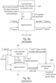
- Fig. 8 illustrates an audio decoder for decoding an encoded audio signal comprising multi-channel audio data comprising data for two or more audio channels, and information on jointly encoded scale parameters.
- the decoder comprises a scale parameter decoder 220 and a signal processor 210, 212, 213 illustrated in Fig. 8a as a single item.
- the scale parameter decoder 220 receives the information on the jointly encoded first group and second group of scale parameters where, preferably, the first group of scale parameters are mid scale parameters and the second group of scale parameters are side scale parameters.
- the signal processor receives the first channel representation of the multi-channel audio data and the second channel representation of the multi-channel audio data and applies the first set of scale parameters to a first channel representation derived from the multi-channel audio data and applies the second set of scale parameters to the second channel representation derived from the multi-channel audio data to obtain the first channel and the second channel of the decoded audio signal at the output of block 210, 212, 213 of Fig. 8a .
- the jointly encoded scale parameters comprise information on the first group of jointly encoded scale parameters such as mid-scale parameters and information on a second group of jointly encoded scale parameters such as side scale parameters.
- the scale parameter decoder 220 is configured to combine a jointly encoded scale parameter of the first group and a jointly encoded scale parameter of the second group using a first combination rule to obtain a scale parameter of the first set of scale parameters and to combine the same both jointly encoded scale parameters of the first and second groups using a second combination rule which is different from the first combination rule to obtain a scale parameter of the second set of scale parameters.
- the scale parameter decoder 220 applies two different combination rules.
- the two different combination rules are a plus or addition combination rule on the one hand and a subtraction or difference combination rule on the other hand.
- the first combination rule can be a multiplication combination rule and the second combination rule can be a quotient or division combination rule.
- all other pairs of combination rules are useful as well depending on the representation of the corresponding scale parameters of the first group and the second group or of the first set and the second set of scale parameters.
- Fig. 8b illustrates a corresponding audio encoder for encoding a multi-channel audio signal comprising two or more channels.
- the audio encoder comprises a scale parameter calculator 140, a signal processor 120 and an encoded signal former 1480, 1500.
- the scale parameter calculator 140 is configured for calculating a first group of jointly encoded scale parameters and a second group of jointly encoded scale parameters from a first set of scale parameters for a first channel of the multi-channel audio signal and from a second set of scale parameters for a second channel of the multi-channel audio signal.
- the signal processor is configured for applying the first set of scale parameters to the first channel of the multi-channel audio signal and for applying the second set of scale parameters to the second channel of the multi-channel audio signal for deriving encoded multi-channel audio data.
- the multi-channel audio data are derived from the scaled first and second channels and the multi-channel audio data are used by the encoded signal former 1480, 1500 together with the information on the first and the second group of jointly encoded scale parameters to obtain the encoded multi-channel audio signal at the output of block 1500 in Fig. 8b .
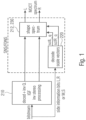
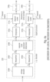
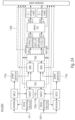
- Fig. 1 illustrates a further implementation of the decoder of Fig. 8a .
- the bitstream is input into the signal processor 210 that performs, typically, entropy decoding and inverse quantization together with intelligent gap filling procedures (IGF procedures) and inverse stereo processing of the scaled or whitened channels.
- the output of block 210 are scaled or whitened decoded left and right or, generally, several decoded channels of a multi-channel signal.
- the bitstream comprises side information bits for the scale parameters for left and right in the case of separate encoding and side information bits for scaled jointly encoded scale parameters illustrated as M, S scale parameters in Fig. 1 .
- This data is introduced into the scale parameter or scale factor decoder 220 that, at its output, generates the decoded left scale factors and the decoded right scale factors that are then applied in the shape spectrum block 212, 230 to finally obtain a preferably MDCT spectrum for left and right that can then be converted into a time domain using a certain inverse MDCT operation.
- Fig. 2 starts from an MDCT spectrum having a left and a right channel that are input into a spectrum shaper 120a, and the output of the spectrum shaper 120a is input into a processor 120b that, for example, performs a stereo processing, intelligent gap filling operations on an encoder side and corresponding quantization and (entropy) coding operations.
- blocks 120a, 120b together represent the signal processor 120 of Fig. 8b .
- SNS spectral noise shaping
- the power spectrum calculator 110a can operate directly on the input signal without an MDCT or MDST spectrum procedure. Another way would be to calculate the power spectrum from a DFT operation rather than an MDCT and an MDST operation, for example.
- the scale factors are calculated by the scale parameter calculator 140 that is illustrated in Fig. 2 as a block quantization encoding of scale factors. Particularly, block 140 outputs, dependent on the similarity between the first and the second channel, either separate encoded scale factors for left and right or jointly encoded scale factors for M and S. This is illustrated in Fig. 2 to the right of block 140.
- block 110b calculates the scale factors for left and right and block 140 then determines, whether separate encoding, i.e., encoding for the left and right scale factors is better or worse than encoding of jointly encoded scale factors, i.e., M and S scale factors derived from the separate scale factors by the two different combination rules such as an addition on the one hand and a subtraction on the other hand.
- separate encoding i.e., encoding for the left and right scale factors is better or worse than encoding of jointly encoded scale factors, i.e., M and S scale factors derived from the separate scale factors by the two different combination rules such as an addition on the one hand and a subtraction on the other hand.
- the result of block 140 are side information bits for L, R or M, S that are, together with the result of block 120b, introduced into an output bitstream illustrated by Fig. 2 .
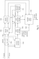
- Fig. 3a illustrates a preferred implementation of the encoder of Fig. 2 or Fig. 8b .
- the first channel is input into a block 1100a that determines the separate scale parameters for the first channel, i.e., for channel L.
- the second channel is input into block 1100b that determines the separate scale parameters for the second channel, i.e., for R.
- the scale parameters for the left channel and the scale parameters for the right channel are correspondingly downsampled by a downsampler 130a for the first channel and a downsampler 130b for the second channel.
- the results are downsampled parameters (DL) for the left channel and downsampled parameters (DR) for the right channel.
- DL downsampled parameters
- DR downsampled parameters
- both these data DL and DR are input into a joint scale parameter determiner 1200.
- the joint scale parameter determiner 1200 generates the first group of jointly encoded scale parameters such as mid or M scale parameters and a second group of jointly encoded scale parameters such as side or S scale parameters. Both groups are input in corresponding vector quantizers 140a, 140b to obtain quantized values that are then, in a final entropy encoder 140c and to be encoded to obtain the information on the jointly encoded scale parameters.
- the entropy encoder 140c may be implemented to perform an arithmetic entropy encoding algorithm or an entropy encoding algorithm with a one-dimensional or with one or more dimensional Huffman code tables.
- FIG. 3b Another implementation of the encoder is illustrated in Fig. 3b , where the downsampling is not performed with the separate scale parameters such as with left and right as illustrated at 130a, 130b in Fig. 3a . Instead, the order of operations of the joint scale parameter determination and the subsequent downsampling by the corresponding downsamplers 130a, 130b is changed. Whether the implementation of Fig. 3a or Fig. 3b is used, depends on the certain implementation, where the implementation of Fig. 3a is preferred, since the joint scale parameter determination 1200 is already performed on the downsampled scale parameters, i.e., the two different combination rules performed by the scale parameter calculator 140 are typically performed on a lower number of inputs compared to the case in Fig. 3b .
- Fig. 4a illustrates the implementation of a decoder for decoding an encoded audio signal having multi-channel audio data comprising data for two or more audio channels and information on jointly encoded scale parameters.
- the decoder in Fig. 4a is only part of the whole decoder of Fig. 8a , since only a part of the signal processor and, particularly, the corresponding channel scalers 212a, 212b are illustrated in Fig. 4a .
- this element comprises an entropy decoder 2200 reversing the procedure performed by corresponding block 140c in Fig. 3a .
- the entropy decoder outputs quantized jointly encoded scale parameters, such as quantized M scale parameters and quantized S scale parameters.
- the corresponding groups of scale parameters are input into dequantizers 2202 and 2204 in order to obtain dequantized values for M and S.
- These dequantized values are then input into a separate scale parameter determiner 2206 that outputs scale parameters for left and right, i.e., separate scale parameters.
- These corresponding scale parameters are input into interpolators 222a, 222b to obtain interpolated scale parameters for left (IL) and interpolated scale parameters for right (IR). Both of these data are input into a channel scaler 212a and 212b, respectively.
- channel scalers correspondingly receive the first channel representation subsequent to the whole procedure done by block 210 in Fig. 1 , for example.
- channel scaler 212b also obtains its corresponding second channel representation as output by block 210 in Fig. 1 .
- a final channel scaling or "shape spectrum" as it is named in Fig. 1 takes place to obtain a shaped spectral channel for left and right that are illustrated as "MDCT spectrum” in Fig. 1 .
- a final frequency domain to time domain conversion for each channel illustrated at 240a, 240b can be performed in order to finally obtain a decoded first channel and a decoded second channel of a multi-channel audio signal in a time domain representation.
- the scale parameter decoder 220 illustrated in the left portion of Fig. 4a can be included within an audio decoder as shown in Fig. 1 or as collectively shown in Fig. 4a , but can also be included as a local decoder within an encoder as will be shown with respect to Fig. 5 explicitly showing the local scale parameter decoder 220 at the output of the scale parameter encoder 140.
- Fig. 4b illustrates a further implementation where, with respect to Fig. 4a , the order of interpolation and scale parameter determination to determine the separate scale parameters is exchanged. Particularly, the interpolation takes place with the jointly encoded scale parameters M and S using interpolators 222a, 222b of Fig. 4b , and the interpolated jointly encoded scale parameters such as IM and IS are input into the separate scale parameter determiner 2206. Then, the output of block 2206 are the upsampled scale parameters, i.e., the scale parameters for each of the, for example, 64 bands illustrated in Fig. 21 .
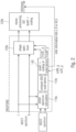
- Fig. 5 illustrates a further preferred implementation of the encoder of Fig. 8b , Fig. 2 or Fig. 3a , Fig. 3b .
- the first channel and the second channel are both introduced into an optional time domain-to-frequency domain converter such as 100a, 100b of Fig. 5 .
- the spectral representation output by blocks 100a, 100b is input into a channel scaler 120a that individually scales the spectral representation for the left and the right channel.
- the channel scaler 120a performs a shape spectrum operation illustrated in 120a of Fig. 2 .
- the output of the channel scaler is input into a channel processor 120b of Fig. 5 , and the processed channels output of the block 120b are input into the encoded signal former 1480,1500 to obtain the encoded audio signal.
- a similarity calculator 1400 receives, as an input, the first channel and the second channel directly in the time domain.
- the similarity calculator can receive the first channel and the second channel at the output of the time domain-to-frequency domain converters 100a, 100b, i.e., the spectral representation.
- the similarity between the two channels is calculated based on the second group of jointly encoded scale parameters, i.e., based on the side scale parameters
- this similarity can also be calculated based on the time domain or spectral domain channels directly without explicit calculation of the jointly encoded scale parameters.
- the similarity can also be determined based on the first group of jointly encoded scale parameters, i.e., based on the mid-scale parameters. Particularly, when the energy of the side scale parameters is lower than a threshold, then it is determined that jointly encoding can be performed.
- the energy of the mid-scale parameters in a frame can also be measured, and determination for a joint encoding can be done when the energy of the mid-scale parameters is greater than another threshold, for example.
- determining the similarity between the first channel and the second channel can be implemented in order to decide for joint coding of scale parameters or separate coding of scale parameters.
- the determination for joint or separate coding of scale parameters does not necessarily have to be identical to the determination of joint stereo coding for the channels, i.e., whether two channels are jointly coded using a mid/side representation or are separately coded in a L, R representation.
- the determination of joint encoding of the scale parameters is done independent on the determination of stereo processing for the actual channels, since the determination of any kind of stereo processing performed in block 120b in Fig. 2 is done after and subsequent to a scaling or shaping of the spectrum using scale factors for mid and side.
- block 140 can determine a joint coding.
- the scale factors for M and S can occur within this block.
- the actually used scale parameters for shaping the spectrum although being scale parameters for left and scale parameters for right are nevertheless derived from the encoded and decoded scale parameters for mid and side.
- a mode decider 1402 receives the output of the similarity calculator 1400 and decides for a separate coding of the scale parameters when the channels are not sufficiently similar. When, however, it is determined that the channels are similar, then a joint coding of the scale parameters is determined by block 1402, and the information, whether the separate or the change joint coding of the scale parameters is applied, is signaled by a corresponding side information or flag 1403 illustrated in Fig. 5 that is provided from block 1402 to the encoded signal former 1480, 1500.
- the encoder comprises the scale parameter encoder 140 that receives the scale parameters for the first channel and the scale parameters for the second channel and encodes the scale parameters either separately or jointly as controlled by the mode decider 1402.
- the scale parameter encoder 140 may, in one embodiment, output the scale parameters for the first and the second channel as indicated by the broken lines so that the channel scaler 120a performs a scaling with the corresponding first and second channel scale parameters.
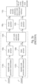
- Fig. 6 illustrates a further preferred embodiment of the present invention with respect to the audio encoder.
- An MDCT spectrum calculator 100 is provided that can, for example, be a time domain to frequency domain converter applying an MDCT algorithm.
- a power spectrum calculator 110a is provided as illustrated in Fig. 2 .
- the separate scale parameters are calculated by a corresponding calculator 1100, and for the purpose of calculating the jointly encoded scale parameters, an addition block 1200a and a subtraction block 1200b. Then, for the purpose of determining the similarity, an energy calculation per frame with the side parameters, i.e., the second group of jointly encoded scale parameters is performed.
- a comparison to a threshold is performed and this block being similar to the mode decider 1402 for the frame of Fig.
- controllable encoder 140 receives the scale parameters calculated by a block 1100, i.e., the separate scale parameters and, additionally, receives the jointly encoded scale parameters, i.e., the ones determined by block 1200a and 1200b.
- Block 140 preferably generates a zero flag for the frame, when block 140 determines that all side parameters of a frame are quantized to 0. This result will occur when the first and the second channel are very close to each other and the differences between the channels and, therefore, the differences between the scale factors are so that these differences are smaller than the lowest quantization threshold applied by the quantizer included in block 140.
- Block 140 outputs the information on the jointly encoded or separately encoded scale parameters for the corresponding frame.
- Fig. 9a illustrates an audio quantizer for quantizing a plurality of audio information items.
- the audio quantizer comprises a first stage vector quantizer 141, 143 for quantizing the plurality of audio information items such as scale factors or scale parameters or spectral values, etc. to determine a first stage vector quantization result 146.
- block 141, 143 generates a plurality of intermediate quantized items corresponding to the first stage vector quantization result.
- the intermediate quantized items are, for example, the values associated with the first stage result.
- the first stage result identifies a certain codebook with, for example, 16 certain (quantized) values
- the intermediate quantized items are the 16 values associated to the codebook vector index being the first stage result 146.
- the intermediate quantized items and the audio information items at the input into the first stage vector quantizer 141, 143 are input into a residual item determiner for calculating a plurality of residual items from the plurality of intermediate quantized items and the plurality of audio information items. This is e.g. done by calculating a difference for each item between the original item and the quantized item.
- the residual items are input into a second stage vector quantizer 145 for quantizing the plurality of residual items to obtain the second stage vector quantization result.
- the first stage vector quantization result at the output of block 141, 143 and the second stage result at the output of block 145 together represent the quantized representation of the plurality of audio information items that is encoded by an optional encoded signal former 1480, 1500 that outputs the quantized audio information items that are, in the preferred embodiment, not only quantized but are additionally entropy encoded.
- the audio dequantizer comprises a first stage vector dequantizer 2220 for dequantizing a first stage quantization result included in the quantized plurality of audio information items to obtain a plurality of intermediate quantized audio information items. Furthermore, a second stage vector dequantizer 2260 is provided and is configured for dequantizing a second stage vector quantization result included in the quantized plurality of audio information items to obtain a plurality of residual items. Both, the intermediate items from block 2220 and the residual items from block 2260 are combined by a combiner 2240 for combining the plurality of intermediate quantized audio items and the plurality of residual items to obtain a dequantized plurality of audio information items.
- the intermediate quantized items at the output of block 2220 are separately encoded scale parameters such as for L and R or the first group of the jointly encoded scale parameters e.g. for M , and the residual items may represent the jointly encoded side scale parameters, for example, i.e., the second group of jointly encoded scale parameters.
- Fig. 7a illustrates a preferred implementation of the first stage vector quantizer 141, 143 of Fig. 9a .
- a vector quantization of a first subset of scale parameters is performed to obtain a first quantization index.
- a vector quantization of a second subset of scale parameters is performed to obtain a second quantization index.
- a vector quantization of a third subset of scale parameters is performed as illustrated in block 703 to obtain a third quantization index that is an optional index.
- the procedure in Fig. 7a is applied when there is a split level quantization. Exemplarily, the audio input signal is separated into 64 bands illustrated in Fig. 21 .
- These 64 bands are downsampled to 16 bands/scale factors, so that the whole band is covered by 16 scale factors.
- These 16 scale factors are quantized by the first stage vector quantizer 141, 143 in a split-level mode illustrated in Fig. 7a .
- the first 8 scale factors of the 16 scale factors of Fig. 21 that are obtained by downsampling the original 64 scale factors are vector-quantized by step 701 and, therefore, represent the first subset of scale parameters.
- the remaining 8 scale parameters for the 8 upper bands represent the second subset of scale parameters that are vector-quantized in step 702.
- a separation of the whole set of scale parameters or audio information items does not necessarily have to be done in exactly two subsets, but can also be done in three subsets or even more subsets.
- the indexes for each level together represent the first stage result. As discussed with respect to Fig. 14 , these indexes can be combined via an index combiner in Fig. 14 to have a single first stage index. Alternatively, the first stage result can consist of the first index, and the second index and a potential third index and probably even more indexes that are not combined, but that are entropy encoded as they are.
- step 701, 702, 703 also provide the intermediate scale parameters that are used in block 704 for the purpose of calculating the residual scale parameters for the frame.
- step 705 that is performed by, for example, block 142 of Fig. 9a , results in the residual scale parameters that are then processed by an (algebraic) vector quantization performed by step 705 in order to generate the second stage result.
- the first stage result and the second stage result are generated for the separate scale parameters L, the separate scale parameters R and the first group of joint scale parameters M.
- the (algebraic) vector quantization of the second group of jointly coded scale parameters or side scale parameters is only performed by step 706 that is in a preferred implementation identical to step 705 and is performed again by block 142 of Fig. 9a .
- the information on the jointly encoded scale parameters for one of the two groups such as the second group preferably related to the side scale parameters does not comprise quantization indices or other quantization bits but only information such as a flag or single bit indicating that the scale parameters for the second group are all zero for a portion or frame of the audio signal or are all at a certain value such as a small value.
- This information is determined by the encoder by an analysis or by other means and is used by the decoder to synthesize the second group of scale parameters based on this information such as by generating zero scale parameters for the time portion or frame of the audio signal or by generating certain value scale parameters or by generating small random scale parameters all being e.g. smaller than the smallest or first quantization stage or is used by the decoder to calculate the first and the second set of scale parameters only using the first group of jointly encoded scale parameters.
- stage 705 in Fig. 7a instead of performing stage 705 in Fig. 7a , only the all zero flag for the second group of jointly encoded scale parameters is written as the second stage result.
- the calculation in block 704 can be omitted as well in this case and can be replaced by a decider for deciding whether the all zero flag is to be activated and transmitted or not.
- This decider can be controlled by a user input indicating a skip of the coding of the S parameters altogether or a bitrate information or can actually perform an analysis of the residual items.
- the scale parameter decoder does not perform any combination but calculates the second set of scale parameters only using the first group of jointly encoded scale parameters such as by dividing the encoded scale parameters of the first group by two or by weighting using another predetermined value.
- the second group of jointly encoded scale parameters is quantized only using the second quantization stage of the two stage quantizer, which preferably is a variable rate quantizer stage.
- the first stage results in all zero quantized values, so that only the second stage is effective. This case is illustrated in Fig. 7b .
- the first quantization stage such as 701, 702, 703 of the two stage quantizer in Fig 7a , which preferably is a fixed rate quantization stage, is applied and the second stage 705 is not used at all for a time portion or frame of the audio signal.
- This case corresponds to a situation, where all the residual items are assumed to be zero or smaller than the smallest or first quantization step size of the second quantization stage.
- Fig. 7b , item 706 would correspond to items 701, 702, 703 of Fig. 7a and item 704 could be omitted as well and can be replaced by a decider for deciding that only the first stage quantization is used or not.
- This decider can be controlled by a user input or a bitrate information or can actually perform an analysis of the residual items to determine that the residual items are small enough so that the accuracy of the second group of jointly encoded scale parameters quantized by the single stage only is sufficient.
- the algebraic vector quantizer 145 additionally performs a split level calculation and, preferably, performs the same split level operation as is performed by the vector quantizer.
- the subsets of the residual values correspond, with respect to the band number, to the subset of scale parameters.
- the algebraic vector quantizer 145 generates the first level result.
- the algebraic vector quantizer 145 generates a second level result for the upper 8 downsampled scale factors or scale parameters or, generally, audio information items.
- the algebraic vector quantizer 145 is implemented as the algebraic vector quantizer defined in section 5.2.3.1.6.9 of ETSI TS 126 445 V13.2.0 (2016-08 ) mentioned as reference (4) where, the result of the corresponding split multi-rate lattice vector quantization is a codebook number for each 8 items, a vector index in the base codebook and an 8-dimensional Voronoi index.
- the codebook number can be avoided and only the vector index in the base codebook and the corresponding n-dimensional Voronoi index is sufficient.
- these items which are item a, item b and item c or only item b and item c for each level for the algebraic vector quantization result represent the second stage quantization result.
- FIG. 10 illustrating a corresponding decoding operation matching with the encoding of Fig. 7a , 7b or the encoding of Fig. 14 in accordance with the first or the second aspect of the present invention or in accordance with both aspects.
- step 2221 of Fig. 10 the quantized mid scale factors, i.e., the second group of jointly encoded scale factors are retrieved. This is done when the stereo mode flag or item 1403 of Fig. 5 indicates a true value. Then, a first stage decoding 2223 and a second stage decoding 2261 is performed in order to re-do the procedures done by the encoder of Fig. 14 and, particularly, by the algebraic vector quantizer 145 described with respect to Fig. 14 or described with respect to Fig. 7a . In step 2225, it is assumed that the side scale factors are all 0. In step 2261, it is checked by means of the 0 flag value, whether there actually come non-zero quantized scale factors for the frame.
- the quantized side scale factors are retrieved and decoded using the second stage decoding 2261 or performing block 706 of Fig. 7b only.
- the jointly encoded scale parameters are transformed back to the separately encoded scale parameters in order to then output the quantized left and right scale parameters that can then be used for inverse scaling of the spectrum in the decoder.
- the stereo mode flag value indicates a value of zero or when it is determined that a separate coding has been used within the frame, then only first stage decoding 2223 and second stage decoding 2261 is performed for the left and right scale factors and, since the left and right scale factors are already in the separately encoded representation, any transformation such as block 2207 is not required.
- the process of efficiently coding and decoding the SNS scale factors that are needed for scaling the spectrum before the stereo processing at the encoder side and after the inverse stereo processing in the decoder side is described below to show a preferred implementation of the present invention as an exemplary pseudo code with comments.
- the indices that are output from the coding process are finally packed to the bitstream and sent to the decoder.
- the AVQ procedure disclosed above for the second stage is preferable implemented as outlined in EVS referring to is the High-Rate LPC (subclause 5.3.3.2.1.3) in the MDCT-based TCX chapter.
- the second-stage Algebraic vector quantizer used it is stated 5.3.3.2.1.3.4 Algebraic vector quantizer, and the algebraic VQ used for quantizing the refinement is described in subclause 5.2.3.1.6.9. .
- one has, for each index, a set of codewords for the base codebook index and set of codewords for the Voronoi index, and all this is entropy coded and therefore of variable bit rate.
- the parameters of the AVQ in each sub-band j consist of the codebook number, the vector index in base codebook and the n- (such as 8-) dimensional Voronoi index.
- the indices are extracted from the bitstream and are used to decode and derive the quantized values of the scale factors.
- a pseudo code example of the procedure is given below.
- the quantized SNS scale factors retrieved from the first stage are refined by decoding the residual in the second stage.
- the procedure is given in the pseudocode below:
- the weighting factors are not calculated separately for each value or split but a single weight or a small number of different weight (as an approximation to avoid complexity) are used to scale all the parameters.
- This scaling is a factor that determines the trade-off of e.g. coarse quantization (more quantizations to zero) bitrate savings and quantization precision (with respective spectral distortion), and can be predetermined in the encoder so that this predetermined value does not have to be transmitted to the decoder but can be fixedly set or initialized in the decoder to save transmission bits. Therefore, a higher scaling of the residual would require more bits but have minimal spectral distortion, while reducing the scale would save additional bits and if spectral distortion is kept in an acceptable range, that could serve as a means of additional bitrate saving.
- Fig. 23 illustrates a comparison in the number of bits for both channels in line with a current prior art implementation (described as "independent” above), the new independent implementation in accordance with the second aspect of the present invention and for the new joint implementation in accordance with the first aspect of the present invention.
- Fig. 23 illustrates a histogram where the vertical axis represents the frequency of occurrence and the horizontal axis illustrates the bins of total number of bits for coding the parameters for both channels.
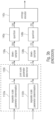
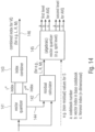
- Fig. 11 illustrates an apparatus for encoding an audio signal 160.
- the audio signal 160 preferably is available in the time-domain, although other representations of the audio signal such as a prediction-domain or any other domain would principally also be useful.
- the apparatus comprises a converter 100, a scale factor calculator 110, a spectral processor 120, a downsampler 130, a scale factor encoder 140 and an output interface 150.
- the converter 100 is configured for converting the audio signal 160 into a spectral representation.
- the scale factor calculator 110 is configured for calculating a first set of scale parameters or scale factors from the spectral representation.
- the other channel is received at block 120, and the scale parameters from the other channels are received by block 140.
- scale factor or “scale parameter” is used in order to refer to the same parameter or value, i.e., a value or parameter that is, subsequent to some processing, used for weighting some kind of spectral values. This weighting, when performed in the linear domain is actually a multiplying operation with a scaling factor.
- scaling does not only mean multiplying or dividing but also means, depending on the certain domain, addition or subtraction or, generally means each operation, by which the spectral value, for example, is weighted or modified using the scale factor or scale parameter.
- the downsampler 130 is configured for downsampling the first set of scale parameters to obtain a second set of scale parameters, wherein a second number of the scale parameters in the second set of scale parameters is lower than a first number of scale parameters in the first set of scale parameters. This is also outlined in the box in Fig. 11 stating that the second number is lower than the first number. As illustrated in Fig. 11 , the scale factor encoder is configured for generating an encoded representation of the second set of scale factors, and this encoded representation is forwarded to the output interface 150.
- the bitrate for transmitting or storing the encoded representation of the second set of scale factors is lower compared to a situation, in which the downsampling of the scale factors performed in the downsampler 130 would not have been performed.
- the spectral processor 120 is configured for processing the spectral representation output by the converter 100 in Fig. 11 using a third set of scale parameters, the third set of scale parameters or scale factors having a third number of scale factors being greater than the second number of scale factors, wherein the spectral processor 120 is configured to use, for the purpose of spectral processing the first set of scale factors as already available from block 110 via line 171.
- the spectral processor 120 is configured to use the second set of scale factors as output by the downsampler 130 for the calculation of the third set of scale factors as illustrated by line 172.
- the spectral processor 120 uses the encoded representation output by the scale factor/parameter encoder 140 for the purpose of calculating the third set of scale factors as illustrated by line 173 in Fig. 11 .
- the spectral processor 120 does not use the first set of scale factors, but uses either the second set of scale factors as calculated by the downsampler or even more preferably uses the encoded representation or, generally, the quantized second set of scale factors and, then, performs an interpolation operation to interpolate the quantized second set of spectral parameters to obtain the third set of scale parameters that has a higher number of scale parameters due to the interpolation operation.
- the encoded representation of the second set of scale factors that is output by block 140 either comprises a codebook index for a preferably used scale parameter codebook or a set of corresponding codebook indices.
- the encoded representation comprises the quantized scale parameters of quantized scale factors that are obtained, when the codebook index or the set of codebook indices or, generally, the encoded representation is input into a decoder-side vector decoder or any other decoder.
- the spectral processor 120 uses the same set of scale factors that is also available at the decoder-side, i.e., uses the quantized second set of scale parameters together with an interpolation operation to finally obtain the third set of scale factors.
- the third number of scale factors in the third set of scale factors is equal to the first number of scale factors.
- a smaller number of scale factors is also useful.
- the scale factor calculator 110 is configured to perform several operations illustrated in Fig. 12 . These operations refer to a calculation 111 of an amplitude-related measure per band, where the spectral representation for one channel is input into block 111. The calculation for the other channel will take place in a similar manner.
- a preferred amplitude-related measure per band is the energy per band, but other amplitude-related measures can be used as well, for example, the summation of the magnitudes of the amplitudes per band or the summation of squared amplitudes which corresponds to the energy.
- powers of 2 used for calculating the energy per band
- powers such as a power of 3 that would reflect the loudness of the signal
- powers different from integer numbers such as powers of 1.5 or 2.5 can be used as well in order to calculate amplitude-related measures per band.
- powers less than 1.0 can be used as long as it is made sure that values processed by such powers are positive- valued.
- a further operation performed by the scale factor calculator can be an inter-band smoothing 112.
- This inter-band smoothing is preferably used to smooth out the possible instabilities that can appear in the vector of amplitude-related measures as obtained by step 111. If one would not perform this smoothing, these instabilities would be amplified when converted to a log-domain later as illustrated at 115, especially in spectral values where the energy is close to 0. However, in other embodiments, inter-band smoothing is not performed.
- a further preferred operation performed by the scale factor calculator 110 is the pre-emphasis operation 113.
- This pre-emphasis operation has a similar purpose as a pre-emphasis operation used in an LPC-based perceptual filter of the MDCT-based TCX processing as discussed before with respect to the prior art. This procedure increases the amplitude of the shaped spectrum in the low-frequencies that results in a reduced quantization noise in the low-frequencies.
- the pre-emphasis operation - as the other specific operations - does not necessarily have to be performed.
- a further optional processing operation is the noise-floor addition processing 114.
- This procedure improves the quality of signals containing very high spectral dynamics such as, for example, Glockenspiel, by limiting the amplitude amplification of the shaped spectrum in the valleys, which has the indirect effect of reducing the quantization noise in the peaks, at the cost of an increase of quantization noise in the valleys, where the quantization noise is anyway not perceptible due to masking properties of the human ear such as the absolute listening threshold, the pre-masking, the post-masking or the general masking threshold indicating that, typically, a quite low volume tone relatively close in frequency to a high volume tone is not perceptible at all, i.e., is fully masked or is only roughly perceived by the human hearing mechanism, so that this spectral contribution can be quantized quite coarsely.
- the noise-floor addition operation 114 does not necessarily have to be performed.
- block 115 indicates a log-like domain conversion.
- a transformation of an output of one of blocks 111, 112, 113, 114 in Fig. 12 is performed in a log-like domain.
- a log-like domain is a domain, in which values close to 0 are expanded and high values are compressed.
- the log domain is a domain with basis of 2, but other log domains can be used as well.
- a log domain with the basis of 2 is better for an implementation on a fixed-point signal processor.
- the output of the scale factor calculator 110 is a first set of scale factors.
- each of the blocks 112 to 115 can be bridged, i.e., the output of block 111, for example, could already be the first set of scale factors. However, all the processing operations and, particularly, the log-like domain conversion are preferred. Thus, one could even implement the scale factor calculator by only performing steps 111 and 115 without the procedures in steps 112 to 114, for example.
- a set of scale parameters for a channel (such as L) is obtained and a set of scale parameters for the other channel (such as R) can also be obtained by a similar calculation.
- the scale factor calculator is configured for performing one or two or more of the procedures illustrated in Fig. 12 as indicated by the input/output lines connecting several blocks.
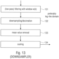
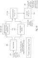
- Fig. 13 illustrates a preferred implementation of the downsampler 130 of Fig. 11 again for a single channel.
- the data for the other channel is calculated in a similar way.
- a low-pass filtering or, generally, a filtering with a certain window w(k) is performed in step 131, and, then, a downsampling/decimation operation of the result of the filtering is performed. Due to the fact that low-pass filtering 131 and in preferred embodiments the downsampling/decimation operation 132 are both arithmetic operations, the filtering 131 and the downsampling 132 can be performed within a single operation as will be outlined later on.
- the downsampling/decimation operation is performed in such a way that an overlap among the individual groups of scale parameters of the first set of scale parameters is performed.
- an overlap of one scale factor in the filtering operation between two decimated calculated parameters is performed.
- step 131 performs a low-pass filter on the vector of scale parameters before decimation.
- This low-pass filter has a similar effect as the spreading function used in psychoacoustic models. It reduces the quantization noise at the peaks, at the cost of an increase of quantization noise around the peaks where it is anyway perceptually masked at least to a higher degree with respect to quantization noise at the peaks.
- the downsampler additionally performs a mean value removal 133 and an additional scaling step 134.
- the low-pass filtering operation 131, the mean value removal step 133 and the scaling step 134 are only optional steps.
- the downsampler illustrated in Fig. 13 or illustrated in Fig. 11 can be implemented to only perform step 132 or to perform two steps illustrated in Fig. 13 such as step 132 and one of the steps 131, 133 and 134.
- the downsampler can perform all four steps or only three steps out of the four steps illustrated in Fig. 13 as long as the downsampling/decimation operation 132 is performed.
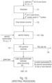
- Fig. 15 illustrates a preferred implementation of the spectral processor.
- the spectral processor 120 included within the encoder of Fig. 11 comprises an interpolator 121 that receives the quantized second set of scale parameters for each channel or alternatively for a group of jointly encoded scale parameters and that outputs the third set of scale parameters for a channel of for a group of jointly encoded scale parameters where the third number is greater than the second number and preferably equal to the first number.
- the spectral processor comprises a linear domain converter 120. Then, a spectral shaping is performed in block 123 using the linear scale parameters on the one hand and the spectral representation on the other hand that is obtained by the converter 100.
- a subsequent temporal noise shaping operation i.e., a prediction over frequency is performed in order to obtain spectral residual values at the output of block 124, while the TNS side information is forwarded to the output interface as indicated by arrow 129.
- the spectral processor 125, 120b has at least one of a scalar quantizer/encoder that is configured for receiving a single global gain for the whole spectral representation, i.e., for a whole frame, and a stereo processing functionality and an IGF processing functionality, etc.
- the global gain is derived depending on certain bitrate considerations.
- the global gain is set so that the encoded representation of the spectral representation generated by block 125, 120b fulfils certain requirements such as a bitrate requirement, a quality requirement or both.
- the global gain can be iteratively calculated or can be calculated in a feed forward measure as the case may be.
- the global gain is used together with a quantizer and a high global gain typically results in a coarser quantization where a low global gain results in a finer quantization.
- a high global gain results in a higher quantization step size while a low global gain results in a smaller quantization step size when a fixed quantizer is obtained.
- other quantizers can be used as well together with the global gain functionality such as a quantizer that has some kind of compression functionality for high values, i.e., some kind of non-linear compression functionality so that, for example, the higher values are more compressed than lower values.
- the bands are non-uniform and follow the perceptually-relevant bark scale (smaller in low-frequencies, larger in high-frequencies).
- this step is mainly used to smooth the possible instabilities that can appear in the vector E B ( b ) . If not smoothed, these instabilities are amplified when converted to log-domain (see step 5), especially in the valleys where the energy is close to 0.
- the pre-emphasis used in this step has the same purpose as the pre-emphasis used in the LPC-based perceptual filter of prior art 2, it increases the amplitude of the shaped Spectrum in the low-frequencies, resulting in reduced quantization noise in the low-frequencies.
- This step improves quality of signals containing very high spectral dynamics such as e.g. glockenspiel, by limiting the amplitude amplification of the shaped spectrum in the valleys, which has the indirect effect of reducing the quantization noise in the peaks, at the cost of an increase of quantization noise in the valleys where it is anyway not perceptible.
- This step applies a low-pass filter (w(k)) on the vector E L ( b ) before decimation.
- This low-pass filter has a similar effect as the spreading function used in psychoacoustic models: it reduces the quantization noise at the peaks, at the cost of an increase of quantization noise around the peaks where it is anyway perceptually masked.
- the mean can be removed without any loss of information. Removing the mean also allows more efficient vector quantization.
- the scaling of 0.85 slightly compress the amplitude of the noise shaping curve. It has a similar perceptual effect as the spreading function mentioned in Step 6: reduced quantization noise at the peaks and increased quantization noise in the valleys.
- the scale factors are quantized using vector quantization, producing indices which are then packed into the bitstream and sent to the decoder, and quantized scale factors scfe ( n ) .
- Interpolation is used to get a smooth noise shaping curve and thus to avoid any big amplitude jumps between adjacent bands.
- Fig. 18 illustrates a preferred implementation of an apparatus for decoding an encoded audio signal 250 (a stereo signal encoded as L, R or M, S) comprising information on an encoded spectral representation and information on an encoded representation of a second set of scale parameters (separately of jointly encoded).
- the decoder comprises an input interface 200, a spectrum decoder 210 (e.g. performing IGF processing or inverse stereo processing or dequantization processing), a scale factor/parameter decoder 220, a spectral processor 230 (e.g. for R, L) and a converter 240 (e.g. for R, L).
- the input interface 200 is configured for receiving the encoded audio signal 250 and for extracting the encoded spectral representation that is forwarded to the spectrum decoder 210 and for extracting the encoded representation of the second set of scale factors that is forwarded to the scale factor decoder 220.
- the spectrum decoder 210 is configured for decoding the encoded spectral representation to obtain a decoded spectral representation that is forwarded to the spectral processor 230.
- the scale factor decoder 220 is configured for decoding the encoded second set of scale parameters to obtain a first set of scale parameters forwarded to the spectral processor 230.
- the first set of scale factors has a number of scale factors or scale parameters that is greater than the number of scale factors or scale parameters in the second set.
- the spectral processor 230 is configured for processing the decoded spectral representation using the first set of scale parameters to obtain a scaled spectral representation.
- the scaled spectral representation is then converted by the converter 240 to finally obtain the decoded audio signal 260 being a stereo signal or a multichannel signal with more than two channels.
- the scale factor decoder 220 is configured to operate in substantially the same manner as has been discussed with respect to the spectral processor 120 of Fig. 11 relating to the calculation of the third set of scale factors or scale parameters as discussed in connection with blocks 141 or 142 and, particularly, with respect to blocks 121, 122 of Fig. 15 .
- the scale factor decoder is configured to perform the substantially same procedure for the interpolation and the transformation back into the linear domain as has been discussed before with respect to step 9.
- the scale factor decoder 220 is configured for applying a decoder codebook 221 to the one or more indices per frame representing the encoded scale parameter representation.
- an interpolation is performed in block 222 that is substantially the same interpolation as has been discussed with respect to block 121 in Fig. 15 .
- a linear domain converter 223 is used that is substantially the same linear domain converter 122 as has been discussed with respect to Fig. 15 .
- blocks 221, 222, 223 can operate different from what has been discussed with respect to the corresponding blocks on the encoder-side.
- the spectrum decoder 210 illustrated in Fig. 18 or 19 comprises a dequantizer/decoder block that receives, as an input, the encoded spectrum and that outputs a dequantized spectrum that is preferably dequantized using the global gain that is additionally transmitted from the encoder side to the decoder side within the encoded audio signal in an encoded form.
- the block 210 may also perform IGF processing or inverse stereo processing such as MS decoding.
- the dequantizer/decoder 210 can, for example, comprise an arithmetic or Huffman decoder functionality that receives, as an input, some kind of codes and that outputs quantization indices representing spectral values.
- these quantization indices are input into a dequantizer together with the global gain and the output are dequantized spectral values that can then be subjected to a TNS processing such as an inverse prediction over frequency in a TNS decoder processing block 211 that, however, is optional.
- a TNS processing such as an inverse prediction over frequency in a TNS decoder processing block 211 that, however, is optional.
- the TNS decoder processing block additionally receives the TNS side information that has been generated by block 124 of Fig. 15 as indicated by line 129.
- the output of the TNS decoder processing step 211 is input into a spectral shaping block 212 operating for each channel separately using the separate scale factors, where the first set of scale factors as calculated by the scale factor decoder are applied to the decoded spectral representation that can or cannot be TNS processed as the case may be, and the output is the scaled spectral representation for each channel that is then input into the converter 240 of Fig. 18 .
- the vector quantizer indices produced in encoder step 8 are read from the bitstream and used to decode the quantized scale factors scfQ ( n ).
- the SNS scale factors g SNS ( b ) are applied on the quantized MDCT frequency lines for each band separately in order to generate the decoded spectrum X ⁇ ( k ) as outlined by the following code.
- Fig. 16 and Fig. 17 illustrate a general encoder/decoder setup where Fig. 16 represents an implementation without TNS processing, while Fig. 17 illustrates an implementation that comprises TNS processing. Similar functionalities illustrated in Fig. 16 and Fig. 17 correspond to similar functionalities in the other figures when identical reference numerals are indicated. Particularly, as illustrated in Fig. 16 , the input signal 160 e.g. a stereo signal or a multichannel signal is input into a transform stage 110 and, subsequently, the spectral processing 120 is performed. Particularly, the spectral processing is reflected by an SNS encoder indicated by reference numerals 123, 110, 130, 140 indicating that the block SNS encoder implements the functionalities indicated by these reference numerals.
- the input signal 160 e.g. a stereo signal or a multichannel signal
- the spectral processing 120 is performed.
- the spectral processing is reflected by an SNS encoder indicated by reference numerals 123, 110, 130, 140 indicating that the block S
- a quantization encoding operation 120b, 125 is performed, and the encoded signal is input into the bitstream as indicated at 180 in Fig. 16 .
- the bitstream 180 then occurs at the decoder-side and subsequent to an inverse quantization and decoding illustrated by reference numeral 210, the SNS decoder operation illustrated by blocks 210, 220, 230 of Fig. 18 are performed so that, in the end, subsequent to an inverse transform 240, the decoded output signal 260 is obtained.
- Fig. 17 illustrates a similar representation as in Fig. 16 , but it is indicated that, preferably, the TNS processing is performed subsequent to SNS processing on the encoder-side and, correspondingly, the TNS processing 211 is performed before the SNS processing 212 with respect to the processing sequence on the decoder-side.
- TNS Temporal Noise Shaping
- SNS Spectral Noise Shaping
- quantization/coding see block diagram below
- TNS Temporal Noise Shaping
- TNS also shapes the quantization noise but does a time-domain shaping (as opposed to the frequency-domain shaping of SNS) as well.
- TNS is useful for signals containing sharp attacks and for speech signals.
- TNS is usually applied (in AAC for example) between the transform and SNS.
- Fig. 20 illustrates a preferred subdivision of the spectral coefficients or spectral lines as obtained by block 100 on the encoder-side into bands. Particularly, it is indicated that lower bands have a smaller number of spectral lines than higher bands.
- Fig. 20 corresponds to the index of bands and illustrates the preferred embodiment of 64 bands and the y-axis corresponds to the index of the spectral lines illustrating 320 spectral coefficients in one frame.
- Fig. 20 illustrates exemplarily the situation of the super wide band (SWB) case where there is a sampling frequency of 32 kHz.
- SWB super wide band
- the situation with respect to the individual bands is so that one frame results in 160 spectral lines and the sampling frequency is 16 kHz so that, for both cases, one frame has a length in time of 10 milliseconds.
- Fig. 21 illustrates more details on the preferred downsampling performed in the downsampler 130 of Fig. 11 or the corresponding upsampling or interpolation as performed in the scale factor decoder 220 of Fig. 18 or as illustrated in block 222 of Fig. 19 .
- the index for the bands 0 to 63 is given. Particularly, there are 64 bands going from 0 to 63.
- the 16 downsample points corresponding to scfQ(i) are illustrated as vertical lines 1100.
- Fig. 21 illustrates how a certain grouping of scale parameters is performed to finally obtain the downsampled point 1100.
- the first block of four bands consists of (0, 1, 2, 3) and the middle point of this first block is at 1.5 indicated by item 1100 at the index 1.5 along the x-axis.
- the second block of four bands is (4, 5, 6, 7), and the middle point of the second block is 5.5.
- the windows 1110 correspond to the windows w(k) discussed with respect to the step 6 downsampling described before. It can be seen that these windows are centered at the downsampled points and there is the overlap of one block to each side as discussed before.
- the interpolation step 222 of Fig. 19 recovers the 64 bands from the 16 downsampled points. This is seen in Fig. 21 by computing the position of any of the lines 1120 as a function of the two downsampled points indicated at 1100 around a certain line 1120.
- the following example exemplifies that.
- Fig. 22a illustrates a schedule for indicating the framing performed on the encoder-side within converter 100.
- Fig. 22b illustrates a preferred implementation of the converter 100 of Fig. 11 on the encoder-side and Fig. 22c illustrates a preferred implementation of the converter 240 on the decoder-side.
- the converter 100 on the encoder-side is preferably implemented to perform a framing with overlapping frames such as a 50% overlap so that frame 2 overlaps with frame 1 and frame 3 overlaps with frame 2 and frame 4.
- a framing with overlapping frames such as a 50% overlap so that frame 2 overlaps with frame 1 and frame 3 overlaps with frame 2 and frame 4.
- other overlaps or a non-overlapping processing can be performed as well, but it is preferred to perform a 50% overlap together with an MDCT algorithm.
- the converter 100 comprises an analysis window 101 and a subsequently-connected spectral converter 102 for performing an FFT processing, an MDCT processing or any other kind of time-to-spectrum conversion processing to obtain a sequence of frames corresponding to a sequence of spectral representations as input in Fig. 11 to the blocks subsequent to the converter 100.
- the scaled spectral representation(s) are input into the converter 240 of Fig. 18 .
- the converter comprises a time-converter 241 implementing an inverse FFT operation, an inverse MDCT operation or a corresponding spectrum-to-time conversion operation.
- the output is inserted into a synthesis window 242 and the output of the synthesis window 242 is input into an overlap-add processor 243 to perform an overlap-add operation in order to finally obtain the decoded audio signal.
- the overlap-add processing in block 243 performs a sample-by-sample addition between corresponding samples of the second half of, for example, frame 3 and the first half of frame 4 so that the audio sampling values for the overlap between frame 3 and frame 4 as indicated by item 1200 in Fig. 22a is obtained. Similar overlap-add operations in a sample-by-sample manner are performed to obtain the remaining audio sampling values of the decoded audio output signal.
- An inventively encoded signal can be stored on a digital storage medium or a non-transitory storage medium or can be transmitted on a transmission medium such as a wireless transmission medium or a wired transmission medium such as the Internet.
- aspects have been described in the context of an apparatus, it is clear that these aspects also represent a description of the corresponding method, where a block or device corresponds to a method step or a feature of a method step. Analogously, aspects described in the context of a method step also represent a description of a corresponding block or item or feature of a corresponding apparatus.
- embodiments of the invention can be implemented in hardware or in software.
- the implementation can be performed using a digital storage medium, for example a floppy disk, a DVD, a CD, a ROM, a PROM, an EPROM, an EEPROM or a FLASH memory, having electronically readable control signals stored thereon, which cooperate (or are capable of cooperating) with a programmable computer system such that the respective method is performed.
- a digital storage medium for example a floppy disk, a DVD, a CD, a ROM, a PROM, an EPROM, an EEPROM or a FLASH memory, having electronically readable control signals stored thereon, which cooperate (or are capable of cooperating) with a programmable computer system such that the respective method is performed.
- Some embodiments comprise a data carrier having electronically readable control signals, which are capable of cooperating with a programmable computer system, such that one of the methods described herein is performed.
- embodiments of the present invention can be implemented as a computer program product with a program code, the program code being operative for performing one of the methods when the computer program product runs on a computer.
- the program code may for example be stored on a machine readable carrier.
- inventions comprise the computer program for performing one of the methods described herein, stored on a machine readable carrier or a non-transitory storage medium.
- an embodiment of the inventive method is, therefore, a computer program having a program code for performing one of the methods described herein, when the computer program runs on a computer.
- a further embodiment of the inventive methods is, therefore, a data carrier (or a digital storage medium, or a computer-readable medium) comprising, recorded thereon, the computer program for performing one of the methods described herein.
- a further embodiment of the inventive method is, therefore, a data stream or a sequence of signals representing the computer program for performing one of the methods described herein.
- the data stream or the sequence of signals may for example be configured to be transferred via a data communication connection, for example via the Internet.
- a further embodiment comprises a processing means, for example a computer, or a programmable logic device, configured to or adapted to perform one of the methods described herein.
- a processing means for example a computer, or a programmable logic device, configured to or adapted to perform one of the methods described herein.
- a further embodiment comprises a computer having installed thereon the computer program for performing one of the methods described herein.
- a programmable logic device for example a field programmable gate array
- a field programmable gate array may cooperate with a microprocessor in order to perform one of the methods described herein.
- the methods are preferably performed by any hardware apparatus.
Landscapes
- Engineering & Computer Science (AREA)
- Physics & Mathematics (AREA)
- Human Computer Interaction (AREA)
- Signal Processing (AREA)
- Multimedia (AREA)
- Health & Medical Sciences (AREA)
- Audiology, Speech & Language Pathology (AREA)
- Acoustics & Sound (AREA)
- Computational Linguistics (AREA)
- Spectroscopy & Molecular Physics (AREA)
- Mathematical Physics (AREA)
- Theoretical Computer Science (AREA)
- General Physics & Mathematics (AREA)
- General Engineering & Computer Science (AREA)
- General Health & Medical Sciences (AREA)
- Compression, Expansion, Code Conversion, And Decoders (AREA)
- Stereophonic System (AREA)
Claims (37)
- Audiodecodierer zum Decodieren eines codierten Audiosignals, das Mehrkanalaudiodaten, die Daten für zwei oder mehr Audiokanäle aufweisen, sowie Informationen über gemeinsam codierte Skalenparameter aufweist, wobei der Audiodecodierer folgende Merkmale aufweist:einen Skalenparameterdecodierer (220) zum Decodieren der Informationen über die gemeinsam codierten Skalenparameter, um eine erste Menge an Skalenparametern für einen ersten Kanal eines decodierten Audiosignals und eine zweite Menge an Skalenparametern für einen zweiten Kanal des decodierten Audiosignals zu erhalten; undeinen Signalprozessor (210, 212, 230) zum Anwenden der ersten Menge an Skalenparametern auf eine erste Kanaldarstellung, die aus den Mehrkanalaudiodaten abgeleitet wird, und zum Anwenden der zweiten Menge an Skalenparametern auf eine zweite Kanaldarstellung, die aus den Mehrkanalaudiodaten abgeleitet wird, um den ersten Kanal und den zweiten Kanal des decodierten Audiosignals zu erhalten,wobei die gemeinsam codierten Skalenparameter Informationen über eine erste Gruppe von gemeinsam codierten Skalenparametern und Informationen über eine zweite Gruppe von gemeinsam codierten Skalenparametern aufweisen, undwobei der Skalenparameterdecodierer (220) dazu konfiguriert ist, einen gemeinsam codierten Skalenparameter der ersten Gruppe und einen gemeinsam codierten Skalenparameter der zweiten Gruppe unter Verwendung einer ersten Kombinationsregel zu kombinieren, um einen Skalenparameter der ersten Menge an Skalenparametern zu erhalten, und unter Verwendung einer zweiten Kombinationsregel, die sich von der ersten Kombinationsregel unterscheidet, zu kombinieren, um einen Skalenparameter der zweiten Menge an Skalenparametern zu erhalten.
- Audiodecodierer gemäß Anspruch 1, wobei die erste Gruppe von gemeinsam codierten Skalenparametern Mittenskalenparameter aufweist und die zweite Gruppe von gemeinsam codierten Skalenparametern Seitenskalenparameter aufweist, und wobei der Skalenparameterdecodierer (220) dazu konfiguriert ist, bei der ersten Kombinationsregel eine Addition zu verwenden und bei der zweiten Kombinationsregel eine Subtraktion zu verwenden.
- Audiodecodierer gemäß Anspruch 1 oder 2, wobei das codierte Audiosignal in einer Sequenz von Rahmen organisiert ist, wobei ein erster Rahmen die Mehrkanalaudiodaten und die Informationen über die gemeinsam codierten Skalenparameter aufweist, und wobei ein zweiter Rahmen separat codierte Skalenparameterinformationen aufweist, und
wobei der Skalenparameterdecodierer (220) dazu konfiguriert ist, zu detektieren, dass der zweite Rahmen die separat codierten Skalenparameterinformationen aufweist, und die erste Menge an Skalenparametern und die zweite Menge an Skalenparametern für den zweiten Rahmen zu berechnen. - Audiodecodierer gemäß Anspruch 3, wobei der erste Rahmen und der zweite Rahmen jeweils Zustandsnebeninformationen aufweisen, die in einem ersten Zustand angeben, dass der erste Rahmen die Informationen über die gemeinsam codierten Skalenparameter aufweist, und in einem zweiten Zustand angeben, dass der zweite Rahmen die separat codierten Skalenparameterinformationen aufweist, und
wobei der Skalenparameterdecodierer (220) dazu konfiguriert ist, die Zustandsnebeninformationen des zweiten Rahmens zu lesen, und auf der Basis der gelesenen Zustandsnebeninformationen zu detektieren, dass der zweite Rahmen die separat codierten Skalenparameterinformationen aufweist, oder die Zustandsnebeninformationen des ersten Rahmens zu lesen und unter Verwendung der gelesenen Zustandsnebeninformationen zu detektieren, dass der erste Rahmen die Informationen über die gemeinsam codierten Skalenparameter aufweist. - Audiodecodierer gemäß einem der vorhergehenden Ansprüche,wobei der Signalprozessor (210, 212, 230) dazu konfiguriert ist, die Mehrkanalaudiodaten zu decodieren, um die erste Kanaldarstellung und die zweite Kanaldarstellung abzuleiten, wobei die erste Kanaldarstellung und die zweite Kanaldarstellung Spektralbereichsdarstellungen mit Spektralabtastwerten sind, undwobei der Signalprozessor (210, 212, 230) dazu konfiguriert ist, jeden Skalenparameter der ersten Menge und der zweiten Menge auf eine entsprechende Mehrzahl der Spektralabtastwerte anzuwenden, um eine geformte Spektraldarstellung des ersten Kanals und eine geformte Spektraldarstellung des zweiten Kanals zu erhalten.
- Audiodecodierer gemäß Anspruch 5, wobei der Signalprozessor (210, 212, 230) dazu konfiguriert ist, die geformte Spektraldarstellung des ersten Kanals und die geformte Spektraldarstellung des zweiten Kanals in einen Zeitbereich zu konvertieren, um eine Zeitbereichsdarstellung des ersten Kanals und eine Zeitbereichsdarstellung des zweiten Kanals des decodierten Audiosignals zu erhalten.
- Audiodecodierer gemäß einem der vorhergehenden Ansprüche, wobei die erste Kanaldarstellung eine erste Anzahl von Bändern aufweist, wobei die erste Menge an Skalenparametern eine zweite Anzahl von Skalenparametern aufweist, wobei die zweite Anzahl kleiner ist als die erste Anzahl, undwobei der Signalprozessor (210, 212, 230) dazu konfiguriert ist, die zweite Anzahl von Skalenparametern zu interpolieren, um eine Anzahl von interpolierten Skalenparametern zu erhalten, die größer als oder gleich groß wie die erste Anzahl von Bändern ist, und wobei der Signalprozessor (210, 212, 230) dazu konfiguriert ist, die erste Kanaldarstellung unter Verwendung der interpolierten Skalenparameter zu skalieren,
oderwobei die erste Kanaldarstellung eine erste Anzahl von Bändern aufweist, wobei die Informationen über die erste Gruppe von gemeinsam codierten Skalenparametern eine zweite Anzahl von gemeinsam codierten Skalenparametern aufweist, wobei die zweite Anzahl kleiner ist als die erste Anzahl,wobei der Skalenparameterdecodierer (220) dazu konfiguriert ist, die zweite Anzahl von gemeinsam codierten Skalenparametern zu interpolieren, um eine Anzahl von interpolierten gemeinsam codierten Skalenparametern zu erhalten, die größer als oder gleich groß wie die erste Anzahl von Bändern ist, undwobei der Skalenparameterdecodierer (220) dazu konfiguriert ist, die interpolierten gemeinsam codierten Skalenparameter zu verarbeiten, um die erste Menge an Skalenparametern und die zweite Menge an Skalenparametern zu bestimmen. - Audiodecodierer gemäß einem der vorhergehenden Ansprüche, wobei das codierte Audiosignal in einer Sequenz von Rahmen organisiert ist, wobei die Informationen über die zweite Gruppe von gemeinsam codierten Skalenparametern in einem bestimmten Rahmen Null-Nebeninformationen aufweist, wobei der Skalenparameterdecodierer (220) dazu konfiguriert ist, die Null-Nebeninformationen zu detektieren, um zu bestimmen, dass die zweite Gruppe von gemeinsam codierten Skalenparametern für den bestimmten Rahmen alle null sind, und
wobei der Skalenparameterdecodierer (220) dazu konfiguriert ist, die Skalenparameter der ersten Menge an Skalenparametern und der zweiten Menge an Skalenparametern lediglich aus der ersten Gruppe von gemeinsam codierten Skalenparametern abzuleiten, oder beim Kombinieren den gemeinsam codierten Skalenparameter der ersten Gruppe und den gemeinsam codierten Skalenparameter der zweiten Gruppe auf Nullwerte oder auf Werte zu setzen, die kleiner als eine Rauschschwelle sind. - Audiodecodierer gemäß einem der vorhergehenden Ansprüche,
wobei der Skalenparameterdecodierer (220) dazu konfiguriert ist:die Informationen über die erste Gruppe von gemeinsam codierten Skalenparametern unter Verwendung eines ersten Dequantisierungsmodus zu dequantisieren, unddie Informationen über die zweite Gruppe von gemeinsam codierten Skalenparametern unter Verwendung eines zweiten Dequantisierungsmodus zu dequantisieren, wobei sich der zweite Dequantisierungsmodus vom ersten Dequantisierungsmodus unterscheidet. - Audiodecodierer gemäß Anspruch 9, wobei der Skalenparameterdecodierer (220) dazu konfiguriert ist, den zweiten Dequantisierungsmodus zu verwenden, dem eine niedrigere oder höhere Quantisierungspräzision zugeordnet ist als dem ersten Dequantisierungsmodus.
- Audiodecodierer gemäß Anspruch 9 oder 10, wobei der Skalenparameterdecodierer (220) dazu konfiguriert ist, als den ersten Dequantisierungsmodus eine erste Dequantisierungsstufe (2220) und eine zweite Dequantisierungsstufe (2260) und einen Kombinierer (2240) zu verwenden, wobei der Kombinierer (2240) als Eingabe ein Ergebnis der ersten Dequantisierungsstufe (2220) und ein Ergebnis der zweiten Dequantisierungsstufe (2260) empfängt, und
als den zweiten Dequantisierungsmodus die zweite Dequantisierungsstufe (2220) des ersten Dequantisierungsmodus zu verwenden, die als Eingabe die Informationen über die zweite Gruppe von gemeinsam codierten Skalenparametern empfängt. - Audiodecodierer gemäß Anspruch 11, wobei die erste Dequantisierungsstufe (2220) eine Vektordequantisierungsstufe ist und wobei die zweite Dequantisierungsstufe (2260) eine Algebravektordequantisierungsstufe ist, oder wobei die erste Dequantisierungsstufe (2220) eine Feste-Rate-Dequantisierungsstufe ist und wobei die zweite Dequantisierungsstufe (2260) eine Variable-Rate-Dequantisierungsstufe ist.
- Audiodecodierer gemäß Anspruch 11 oder 12, wobei die Informationen über die erste Gruppe von gemeinsam codierten Skalenparametern für einen Rahmen des codierten Audiosignals zwei oder mehr Indizes aufweisen und wobei die Informationen über die zweite Gruppe von gemeinsam codierten Skalenparametern einen einzelnen Index oder eine geringere Anzahl von Indizes oder dieselbe Anzahl von Indizes wie bei der ersten Gruppe aufweisen, und
wobei der Skalenparameterdecodierer (220) dazu konfiguriert ist, in der ersten Dequantisierungsstufe (2220) für jeden Index der zwei oder mehr Indizes gemeinsam codierte Zwischenskalenparameter der ersten Gruppe zu bestimmen und wobei der Skalenparameterdecodierer (220) dazu konfiguriert ist, in der zweiten Dequantisierungsstufe (2260) gemeinsam codierte Restskalenparameter der ersten Gruppe aus dem einzelnen oder der kleineren oder derselben Anzahl von Indizes der Informationen über die erste Gruppe von gemeinsam codierten Skalenparametern zu berechnen und, durch den Kombinierer (2240) der ersten Gruppe von gemeinsam codierten Skalenparamatern, aus den gemeinsam codierten Zwischenskalenparametern der ersten Gruppe und den gemeinsam codierten Restskalenparametern der ersten Gruppe die erste Gruppe von gemeinsam codierten Skalenparametern zu berechnen. - Audiodecodierer gemäß einem der Ansprüche 11 bis 13, wobei die erste Dequantisierungsstufe (2220) ein Verwenden eines Index für ein erstes Codebuch mit einer ersten Anzahl von Einträgen oder ein Verwenden eines Index, der eine erste Präzision darstellt, aufweist, wobei die zweite Dequantisierungsstufe (2260) ein Verwenden eines Index für ein zweites Codebuch mit einer zweiten Anzahl von Einträgen oder ein Verwenden eines Index, der eine zweite Präzision darstellt, aufweist, und wobei die zweite Anzahl geringer ist oder höher ist als die erste Anzahl oder die zweite Präzision geringer oder höher ist als die erste Präzision.
- Audiodecodierer gemäß einem der vorhergehenden Ansprüche, wobei die Informationen über die zweite Gruppe von gemeinsam codierten Skalenparametern angeben, dass die zweite Gruppe von gemeinsam codierten Skalenparametern alle null sind oder auf einem bestimmten Wert für einen Rahmen des codierten Audiosignals sind, und wobei der Skalenparameterdecodierer (220) dazu konfiguriert ist, beim Kombinieren unter Verwendung der ersten Regel oder der zweiten Regel einen gemeinsam codierten Skalenparameter, der null ist oder auf einem bestimmten Wert liegt, zu verwenden, oder
wobei, für den Rahmen, der die Informationen aufweist, die alle null sind oder bei einem bestimmten Wert sind, der Skalenparameterdecodierer (220) dazu konfiguriert ist, die zweite Menge an Skalenparametern lediglich unter Verwendung der ersten Gruppe von gemeinsam codierten Skalenparametern ohne eine Kombinationsoperation zu bestimmen. - Audiodecodierer gemäß einem der Ansprüche 9 oder 10, wobei der Skalenparameterdecodierer (220) dazu konfiguriert ist, als den ersten Dequantisierungsmodus die erste Dequantisierungsstufe (2220) und die zweite Dequantisierungsstufe (2260) und den Kombinierer (2240) zu verwenden, wobei der Kombinierer (2240) als Eingabe ein Ergebnis der ersten Dequantisierungsstufe (2220) und ein Ergebnis der zweiten Dequantisierungsstufe (2260) empfängt, und als den zweiten Dequantisierungsmodus die erste Dequantisierungsstufe (2220) des ersten Dequantisierungsmodus zu verwenden.
- Audiocodierer zum Codieren eines Mehrkanalaudiosignals, das zwei oder mehr Kanäle aufweist, wobei der Audiocodierer folgende Merkmale aufweist:einen Skalenparameterrechner (140) zum Berechnen einer ersten Gruppe von gemeinsam codierten Skalenparametern und einer zweiten Gruppe von gemeinsam codierten Skalenparametern aus einer ersten Menge an Skalenparametern für einen ersten Kanal des Mehrkanalaudiosignals und aus einer zweiten Menge an Skalenparametern für einen zweiten Kanal des Mehrkanalaudiosignals;einen Signalprozessor (120) zum Anwenden der ersten Menge an Skalenparametern auf den ersten Kanal des Mehrkanalaudiosignals und zum Anwenden der zweiten Menge an Skalenparametern auf den zweiten Kanal des Mehrkanalaudiosignals und zum Ableiten von Mehrkanalaudiodaten; undeinen Codiertes-Signal-Bilder (1480, 1500) zum Verwenden der Mehrkanalaudiodaten und von Informationen über die erste Gruppe von gemeinsam codierten Skalenparametern und von Informationen über die zweite Gruppe von gemeinsam codierten Skalenparametern, um ein codiertes Mehrkanalaudiosignal zu erhalten.
- Audiocodierer gemäß Anspruch 17, wobei der Signalprozessor (120) dazu konfiguriert ist, beim Anwendendie erste Gruppe von gemeinsam codierten Skalenparametern und die zweite Gruppe von gemeinsam codierten Skalenparametern zu codieren, um die Informationen über die erste Gruppe von gemeinsam codierten Skalenparametern und die Informationen über die zweite Gruppe von gemeinsam codierten Skalenparametern zu erhalten,die Informationen über die erste und die zweite Gruppe von gemeinsam codierten Skalenparametern lokal zu decodieren, um eine lokal decodierte erste Menge an Skalenparametern und eine lokal decodierte zweite Menge an Skalenparametern zu erhalten, undden ersten Kanal unter Verwendung der lokal decodierten ersten Menge an Skalenparametern zu skalieren und den zweiten Kanal unter Verwendung der lokal decodierten zweiten Menge an Skalenparametern zu decodieren, oderwobei der Signalprozessor (120) dazu konfiguriert ist, beim Anwendendie erste Gruppe von gemeinsam codierten Skalenparametern und die zweite Gruppe von gemeinsam codierten Skalenparametern zu quantisieren, um eine quantisierte erste Gruppe von gemeinsam codierten Skalenparametern und eine quantisierte zweite Gruppe von gemeinsam codierten Skalenparametern zu erhalten,die quantisierte erste und zweite Gruppe von gemeinsam codierten Skalenparametern lokal zu decodieren, um eine lokal decodierte erste Menge an Skalenparametern und eine lokal decodierte zweite Menge an Skalenparametern zu erhalten, undden ersten Kanal unter Verwendung der lokal decodierten ersten Menge an Skalenparametern zu skalieren und den zweiten Kanal unter Verwendung der lokal decodierten zweiten Menge an Skalenparametern zu skalieren.
- Audiocodierer gemäß Anspruch 17 oder 18,
wobei der Skalenparameterrechner (140) dazu konfiguriert ist, einen Skalenparameter der ersten Menge an Skalenparametern und einen Skalenparameter der zweiten Menge an Skalenparametern unter Verwendung einer ersten Kombinationsregel zu kombinieren, um einen gemeinsam codierten Skalenparameter der ersten Gruppe von gemeinsam codierten Skalenparametern zu erhalten, und unter Verwendung einer zweiten Kombinationsregel, die sich von der ersten Kombinationsregel unterscheidet, zu kombinieren, um einen gemeinsam codierten Skalenparameter der zweiten Gruppe von gemeinsam codierten Skalenparametern zu erhalten. - Audiocodierer gemäß Anspruch 19, wobei die erste Gruppe von gemeinsam codierten Skalenparametern Mittenskalenparameter aufweist und die zweite Gruppe von gemeinsam codierten Skalenparametern Seitenskalenparameter aufweist, wobei der Skalenparameterrechner (140) dazu konfiguriert ist, bei der ersten Kombinationsregel eine Addition zu verwenden und bei der zweiten Kombinationsregel eine Subtraktion zu verwenden.
- Audiocodierer gemäß einem der Ansprüche 17 bis 20, wobei der Skalenparameterrechner dazu konfiguriert ist, eine Sequenz von Rahmen des Mehrkanalaudiosignals zu verarbeiten,wobei der Skalenparameterrechner (140) dazu konfiguriert ist,erste und zweite Gruppen von gemeinsam codierten Skalenparametern für einen ersten Rahmen der Sequenz von Rahmen zu berechnen, undeinen zweiten Rahmen der Sequenz von Rahmen zu analysieren, um einen separaten Codiermodus für den zweiten Rahmen zu bestimmen, undwobei der Codiertes-Signal-Bilder (1480, 1500) dazu konfiguriert ist, Zustandsnebeninformationen in das codierte Audiosignal, die einen separaten Codiermodus für den zweiten Rahmen oder einen gemeinsamen Codiermodus für den ersten Rahmen angeben, und Informationen über die erste Menge und die zweite Menge an separat codierten Skalenparametern für den zweiten Rahmen einzufügen.
- Audiocodierer gemäß einem der Ansprüche 17 bis 21, wobei der Skalenparameterrechner (140) dazu konfiguriert ist,die erste Menge an Skalenparametern für den ersten Kanal zu berechnen und die zweite Menge an Skalenparametern für den zweiten Kanal zu berechnen,die erste und die zweite Menge an Skalenparametern abwärts-abzutasten, um eine abwärts-abgetastete erste Menge und eine abwärts-abgetastete zweite Menge zu erhalten; undeinen Skalenparameter aus der abwärts-abgetasteten ersten Menge und der abwärts-abgetasteten zweiten Menge unter Verwendung unterschiedlicher Kombinationsregeln zu kombinieren, um einen gemeinsam codierten Skalenparameter der ersten Gruppe und einen gemeinsam codierten Skalenparameter der zweiten Gruppe zu erhalten oderwobei der Skalenparameterrechner (140) dazu konfiguriert ist,die erste Menge an Skalenparametern für den ersten Kanal und die zweite Menge an Skalenparametern für den zweiten Kanal zu berechnen,einen Skalenparameter aus der ersten Menge und einen Skalenparameter aus der zweiten Menge unter Verwendung unterschiedlicher Kombinationsregeln zu kombinieren, um einen gemeinsam codierten Skalenparameter der ersten Gruppe und einen gemeinsam codierten Skalenparameter der zweiten Gruppe zu erhalten, unddie erste Gruppe von gemeinsam codierten Skalenparametern abwärts-abzutasten, um eine abwärts-abgetastete erste Gruppe von gemeinsam codierten Skalenparametern zu erhalten, und die zweite Gruppe von gemeinsam codierten Skalenparametern abwärts-abzutasten, um eine abwärts-abgetastete zweite Gruppe von gemeinsam codierten Skalenparametern zu erhalten,wobei die abwärts-abgetastete erste Gruppe und die abwärts-abgetastete zweite Gruppe die Informationen über die erste Gruppe von gemeinsam codierten Skalenparametern und die Informationen über die zweite Gruppe von gemeinsam codierten Skalenparametern darstellen.
- Audiocodierer gemäß einem der Ansprüche 21 oder 22,
wobei der Skalenparameterrechner (140) dazu konfiguriert ist, eine Ähnlichkeit des ersten Kanals und des zweiten Kanals in dem zweiten Rahmen zu berechnen, und den separaten Codiermodus zu bestimmen, falls eine berechnete Ähnlichkeit in einer ersten Beziehung zu einer Schwelle steht, oder den gemeinsamen Codiermodus zu bestimmen, falls die berechnete Ähnlichkeit in einer unterschiedlichen zweiten Beziehung zu der Schwelle steht. - Audiocodierer gemäß Anspruch 23, wobei der Skalenparameterrechner (140) dazu konfiguriert ist,für den zweiten Rahmen eine Differenz zwischen dem Skalenparameter der ersten Menge und dem Skalenparameter der zweiten Menge für jedes Band zu berechnen,jede Differenz des zweiten Rahmens zu verarbeiten, so dass negative Vorzeichen entfernt werden, um verarbeitete Differenzen des zweiten Rahmens zu erhalten,die verarbeiteten Differenzen zu kombinieren, um ein Ähnlichkeitsmaß zu erhalten,das Ähnlichkeitsmaß mit der Schwelle zu vergleichen, undsich für den separaten Codiermodus zu entscheiden, wenn das Ähnlichkeitsmaß größer als die Schwelle ist, oder sich für den gemeinsamen Codiermodus zu entscheiden, wenn das Ähnlichkeitsmaß kleiner als die Schwelle ist.
- Audiocodierer gemäß einem der Ansprüche 17 bis 24, wobei der Signalprozessor (120) dazu konfiguriert ist,die erste Gruppe von gemeinsam codierten Skalenparametern unter Verwendung einer Erste-Stufe-Quantisierungsfunktion (141, 143) zu quantisieren, um einen oder mehrere erste Quantisierungsindizes als ein Erste-Stufe-Ergebnis zu erhalten und eine erste Zwischengruppe von gemeinsam codierten Skalenparametern zu erhalten,eine erste Restgruppe von gemeinsam codierten Skalenparametern aus der ersten Gruppe von gemeinsam codierten Skalenparametern zu berechnen und der ersten Zwischengruppe von gemeinsam codierten Skalenparametern zu berechnen (142), unddie erste Restgruppe von gemeinsam codierten Skalenparametern unter Verwendung einer Zweite-Stufe-Quantisierungsfunktion (145) zu quantisieren, um einen oder mehrere Quantisierungsindizes als Zweite-Stufe-Ergebnis zu erhalten.
- Audiocodierer gemäß einem der Ansprüche 17 bis 25,wobei der Signalprozessor (120) dazu konfiguriert ist, die zweite Gruppe von gemeinsam codierten Skalenparametern unter Verwendung einer Einzelstufenquantisierungsfunktion zu quantisieren, um einen oder mehrere Quantisierungsindizes als das Einzelstufenergebnis zu erhalten, oderwobei der Signalprozessor (120) konfiguriert ist zum Quantisieren der ersten Gruppe von gemeinsam codierten Skalenparametern unter Verwendung zumindest einer Erste-Stufe-Quantisierungsfunktion und einer Zweite-Stufe-Quantisierungsfunktion, wobei der Signalprozessor (120) konfiguriert ist zum Quantisieren der zweiten Gruppe von gemeinsam codierten Skalenparametern unter Verwendung einer Einzelstufenquantisierungsfunktion, wobei die Einzelstufenquantisierungsfunktion aus der Erste-Stufe-Quantisierungsfunktion und der Zweite-Stufe-Quantisierungsfunktion ausgewählt wird.
- Audiocodierer gemäß einem der Ansprüche 21 bis 26, wobei der Skalenparameterrechner (140) dazu konfiguriert ist,die erste Menge an Skalenparametern unter Verwendung einer Erste-Stufe-Quantisierungsfunktion (141, 143) zu quantisieren, um einen oder mehrere erste Quantisierungsindizes als ein Erstes-Stufe-Ergebnis zu erhalten und eine erste Zwischenmenge an Skalenparametern zu erhalten,eine erste Restmenge an Skalenparametern aus der ersten Menge an Skalenparametern und der ersten Zwischenmenge an Skalenparametern zu berechnen (142), unddie erste Restmenge an Skalenparametern unter Verwendung einer Zweite-Stufe-Quantisierungsfunktion (145) zu quantisieren, um einen oder mehrere Quantisierungsindizes als ein Zweite-Stufe-Ergebnis zu erhalten,oder
wobei der Skalenparameterrechner (140) dazu konfiguriert ist,die zweite Menge an Skalenparametern unter Verwendung einer Erste-Stufe-Quantisierungsfunktion (141, 143) zu quantisieren, um einen oder mehrere erste Quantisierungsindizes als ein Erste-Stufe-Ergebnis zu erhalten und eine zweite Zwischenmenge an Skalenparametern zu erhalten,eine zweite Restmenge an Skalenparametern aus der zweiten Menge an Skalenparametern und der zweiten Zwischenmenge an Skalenparametern zu berechnen (142), unddie zweite Restmenge an Skalenparametern unter Verwendung einer Zweite-Stufe-Quantisierungsfunktion (145) zu quantisieren, um einen oder mehrere Quantisierungsindizes als Zweite-Stufe-Ergebnis zu erhalten. - Audiocodierer gemäß Anspruch 25 oder 27,wobei die Zweite-Stufe-Quantisierungsfunktion (145) einen Verstärkungs- oder Gewichtungswert kleiner als 1 verwendet, um die erste Restgruppe an gemeinsam codierten Skalenparametern oder die erste oder zweite Restmenge an Skalenparametern zu erhöhen, bevor eine Vektorquantisierung ausgeführt wird, wobei die Vektorquantisierung unter Verwendung erhöhter Restwerte ausgeführt wird, und/oderwobei, exemplarisch, der Gewichtungs- oder Verstärkungswert dazu verwendet wird, einen Skalierungsparameter durch den Gewichtungs- oder Verstärkungswert zu teilen, wobei der Gewichtungswert vorzugsweise zwischen 0,1 und 0,9 liegt und weiter bevorzugt zwischen 0,2 und 0,6 liegt oder noch weiter bevorzugt zwischen 0,25 und 0,4 liegt, und/oderwobei derselbe Verstärkungswert für alle Skalierungsparameter der ersten Restgruppe von gemeinsam codierten Skalierungsparametern verwendet wird oder die erste oder zweite Restmenge an Skalenparametern verwendet wird.
- Audiocodierer gemäß einem der Ansprüche 25 bis 28,wobei die Erste-Stufe-Quantisierungsfunktion (141, 143) zumindest ein Codebuch mit einer ersten Anzahl von Einträgen aufweist, die einer ersten Größe des einen oder der mehreren Quantisierungsindizes entspricht,wobei die Zweite-Stufe-Quantisierungsfunktion (145) oder die Einzelstufenquantisierungsfunktion zumindest ein Codebuch mit einer zweiten Anzahl von Einträgen aufweist, die einer zweiten Größe des einen oder der mehreren Quantisierungsindizes entspricht, undwobei die erste Anzahl größer oder kleiner als die zweite Anzahl oder die erste Größe größer oder kleiner als die zweite Größe ist, oderwobei die Erste-Stufe-Quantisierungsfunktion (141, 143) eine Feste-Rate-Quantisierungsfunktion ist und wobei die Zweite-Stufe-Quantisierungsfunktion (145) eine Variable-Rate-Quantisierungsfunktion ist.
- Audiocodierer gemäß einem der Ansprüche 17 bis 29, wobei der Skalenparameterrechner (140) dazu konfiguriert ist,eine erste MDCT-Darstellung für den ersten Kanal und eine zweite MDCT-Darstellung für den zweiten Kanal zu empfangen,eine erste MDST-Darstellung für den ersten Kanal und eine zweite MDST-Darstellung für den zweiten Kanal zu empfangen,ein erstes Leistungsspektrum für den ersten Kanal aus der ersten MDCT-Darstellung und der ersten MDST-Darstellung und ein zweites Leistungsspektrum für den zweiten Kanal aus der zweiten MDCT-Darstellung und der zweiten MDST-Darstellung zu berechnen, unddie erste Menge an Skalenparametern für den ersten Kanal aus dem ersten Leistungsspektrum zu berechnen und die zweite Menge an Skalenparametern für den zweiten Kanal aus dem zweiten Leistungsspektrum zu berechnen.
- Audiocodierer gemäß Anspruch 30,
wobei der Signalprozessor (120) dazu konfiguriert ist, die erste MDCT-Darstellung unter Verwendung von Informationen, die aus der ersten Menge an Skalenparametern abgeleitet werden, zu skalieren, und die zweite MDCT-Darstellung unter Verwendung von Informationen, die aus der zweiten Menge an Skalenparametern abgeleitet werden, zu skalieren. - Audiocodierer gemäß einem der Ansprüche 17 bis 31,wobei der Signalprozessor (120) dazu konfiguriert ist, eine skalierte erste Kanaldarstellung und eine skalierte zweite Kanaldarstellung unter Verwendung einer gemeinsamen Mehrkanalverarbeitung weiterzuverarbeiten, um eine Mehrkanal-verarbeitete Darstellung des Mehrkanalaudiosignals abzuleiten, oderwobei der Signalprozessor (120) dazu konfiguriert ist, eine skalierte erste Kanaldarstellung und eine skalierte zweite Kanaldarstellung unter Verwendung einer gemeinsamen Mehrkanalverarbeitung weiterzuverarbeiten, um eine Mehrkanal-verarbeitete Darstellung des Mehrkanalaudiosignals abzuleiten, und die Mehrkanal-verarbeitete Darstellung des Mehrkanalaudiosignals unter Verwendung einer Spektralbandreplikationsverarbeitung oder einer Intelligente-Lückenfüllung-Verarbeitung oder einer Bandbreitenerweiterungsverarbeitung weiterzuverarbeiten, um eine Darstellung der Kanäle des Mehrkanalaudiosignals zu erhalten, und die Darstellung der Kanäle des Mehrkanalaudiosignals zu quantisieren und zu codieren, um die Mehrkanalaudiodaten zu erhalten.
- Audiocodierer gemäß einem der Ansprüche 17 bis 32, der dazu konfiguriert ist, für einen Rahmen des Mehrkanalaudiosignals die Informationen über die zweite Gruppe von gemeinsam codierten Skalenparametern als Informationen, die alle null sind oder alle einen bestimmten Wert aufweisen, zu bestimmen, die denselben Wert oder einen Nullwert für alle gemeinsam codierten Skalenparameter des Rahmens angeben, oder wobei der Codiertes-Signal-Bilder (1480, 1500) dazu konfiguriert ist, die Informationen, die alle null sind oder alle einen bestimmten Wert aufweisen, zu verwenden, um das codierte Mehrkanalaudiosignal zu erhalten.
- Audiocodierer gemäß einem der Ansprüche 17 bis 33, wobei der Skalenparameterrechner (140) konfiguriert istzum Berechnen der ersten Gruppe von gemeinsam codierten Skalenparametern und der zweiten Gruppe von gemeinsam codierten Skalenparametern für einen ersten Rahmen,zum Berechnen der ersten Gruppe von gemeinsam codierten Skalenparametern für einen zweiten Rahmen,wobei in dem zweiten Rahmen die gemeinsam codierten Skalenparameter nicht berechnet oder codiert werden, undwobei der Codiertes-Signal-Bilder (1480, 1500) dazu konfiguriert ist, eine Kennzeichnung als die Informationen der zweiten Gruppe von gemeinsam codierten Skalenparametern zu verwenden, die angibt, dass in dem zweiten Rahmen jegliche gemeinsam codierten Skalenparameter der zweiten Gruppe nicht in dem codierten Mehrkanalaudiosignal enthalten sind.
- Verfahren zum Decodieren eines codierten Audiosignals, das Mehrkanalaudiodaten, die Daten für zwei oder mehr Audiokanäle aufweisen, sowie Informationen über gemeinsam codierte Skalenparameter aufweist, wobei das Verfahren folgende Schritte aufweist:Decodieren der Informationen über die gemeinsam codierten Skalenparameter, um eine erste Menge an Skalenparametern für einen ersten Kanal eines decodierten Audiosignals und eine zweite Menge an Skalenparametern für einen zweiten Kanal des decodierten Audiosignals zu erhalten; undAnwenden der ersten Menge an Skalenparametern auf eine erste Kanaldarstellung, die aus den Mehrkanalaudiodaten abgeleitet wird, und zum Anwenden der zweiten Menge an Skalenparametern auf eine zweite Kanaldarstellung, die aus den Mehrkanalaudiodaten abgeleitet wird, um den ersten Kanal und den zweiten Kanal des decodierten Audiosignals zu erhalten,wobei die gemeinsam codierten Skalenparameter Informationen über eine erste Gruppe von gemeinsam codierten Skalenparametern und Informationen über eine zweite Gruppe von gemeinsam codierten Skalenparametern aufweisen, undwobei das Decodieren ein Kombinieren eines gemeinsam codierten Skalenparameters der ersten Gruppe und eines gemeinsam codierten Skalenparameters der zweiten Gruppe unter Verwendung einer ersten Kombinationsregel aufweist, um einen Skalenparameter der ersten Menge an Skalenparametern zu erhalten, und unter Verwendung einer zweiten Kombinationsregel, die sich von der ersten Kombinationsregel unterscheidet, um einen Skalenparameter der zweiten Menge an Skalenparametern zu erhalten.
- Ein Verfahren zum Codieren eines Mehrkanalaudiosignals, das zwei oder mehr Kanäle aufweist, mit folgenden Schritten:Berechnen einer ersten Gruppe von gemeinsam codierten Skalenparametern und einer zweiten Gruppe von gemeinsam codierten Skalenparametern aus einer ersten Menge an Skalenparametern für einen ersten Kanal des Mehrkanalaudiosignals und aus einer zweiten Menge an Skalenparametern für einen zweiten Kanal des Mehrkanalaudiosignals;Anwenden der ersten Menge an Skalenparametern auf den ersten Kanal des Mehrkanalaudiosignals und zum Anwenden der zweiten Menge an Skalenparametern auf den zweiten Kanal des Mehrkanalaudiosignals und zum Ableiten von Mehrkanalaudiodaten; undVerwenden der Mehrkanalaudiodaten und von Informationen über die erste Gruppe von gemeinsam codierten Skalenparametern und von Informationen über die zweite Gruppe von gemeinsam codierten Skalenparametern, um ein codiertes Mehrkanalaudiosignal zu erhalten.
- Computerprogramm zum Ausführen, wenn dasselbe auf einem Computer oder Prozessor abläuft, des Verfahrens gemäß Anspruch 35 oder 36.
Applications Claiming Priority (2)
| Application Number | Priority Date | Filing Date | Title |
|---|---|---|---|
| EP20184555 | 2020-07-07 | ||
| PCT/EP2021/068520 WO2022008448A1 (en) | 2020-07-07 | 2021-07-05 | Audio decoder, audio encoder, and related methods using joint coding of scale parameters for channels of a multi-channel audio signal |
Publications (3)
| Publication Number | Publication Date |
|---|---|
| EP4179529A1 EP4179529A1 (de) | 2023-05-17 |
| EP4179529B1 true EP4179529B1 (de) | 2024-10-30 |
| EP4179529C0 EP4179529C0 (de) | 2024-10-30 |
Family
ID=71661617
Family Applications (3)
| Application Number | Title | Priority Date | Filing Date |
|---|---|---|---|
| EP21742334.2A Active EP4179531B1 (de) | 2020-07-07 | 2021-07-05 | Audioquantisierer und audiodequantisierer und zugehörige verfahren |
| EP24184655.9A Withdrawn EP4447044A3 (de) | 2020-07-07 | 2021-07-05 | Audioquantisierer und audiodequantisierer und zugehörige verfahren |
| EP21742333.4A Active EP4179529B1 (de) | 2020-07-07 | 2021-07-05 | Audiodecodierer, audiocodierer und zugehörige verfahren mit gemeinsamer codierung von skalenparametern für kanäle eines mehrkanalaudiosignals |
Family Applications Before (2)
| Application Number | Title | Priority Date | Filing Date |
|---|---|---|---|
| EP21742334.2A Active EP4179531B1 (de) | 2020-07-07 | 2021-07-05 | Audioquantisierer und audiodequantisierer und zugehörige verfahren |
| EP24184655.9A Withdrawn EP4447044A3 (de) | 2020-07-07 | 2021-07-05 | Audioquantisierer und audiodequantisierer und zugehörige verfahren |
Country Status (14)
| Country | Link |
|---|---|
| US (2) | US20230133513A1 (de) |
| EP (3) | EP4179531B1 (de) |
| JP (3) | JP7581477B2 (de) |
| KR (2) | KR20230066547A (de) |
| CN (2) | CN115843378A (de) |
| AU (2) | AU2021303726B2 (de) |
| BR (2) | BR112022026703A2 (de) |
| CA (2) | CA3184522A1 (de) |
| ES (2) | ES2994675T3 (de) |
| MX (2) | MX2023000340A (de) |
| PL (2) | PL4179529T3 (de) |
| TW (2) | TWI841856B (de) |
| WO (2) | WO2022008454A1 (de) |
| ZA (2) | ZA202213859B (de) |
Families Citing this family (4)
| Publication number | Priority date | Publication date | Assignee | Title |
|---|---|---|---|---|
| WO2022008454A1 (en) | 2020-07-07 | 2022-01-13 | Fraunhofer-Gesellschaft zur Förderung der angewandten Forschung e.V. | Audio quantizer and audio dequantizer and related methods |
| GB2623516A (en) * | 2022-10-17 | 2024-04-24 | Nokia Technologies Oy | Parametric spatial audio encoding |
| WO2024175187A1 (en) * | 2023-02-21 | 2024-08-29 | Fraunhofer-Gesellschaft zur Förderung der angewandten Forschung e.V. | Encoder for encoding a multi-channel audio signal |
| TWI864704B (zh) * | 2023-04-26 | 2024-12-01 | 弗勞恩霍夫爾協會 | 用於音訊編碼器中之尺度參數之諧度相依傾斜控制之設備及方法 |
Family Cites Families (28)
| Publication number | Priority date | Publication date | Assignee | Title |
|---|---|---|---|---|
| JP3246715B2 (ja) | 1996-07-01 | 2002-01-15 | 松下電器産業株式会社 | オーディオ信号圧縮方法,およびオーディオ信号圧縮装置 |
| US5966688A (en) * | 1997-10-28 | 1999-10-12 | Hughes Electronics Corporation | Speech mode based multi-stage vector quantizer |
| US6148283A (en) * | 1998-09-23 | 2000-11-14 | Qualcomm Inc. | Method and apparatus using multi-path multi-stage vector quantizer |
| US20030215013A1 (en) * | 2002-04-10 | 2003-11-20 | Budnikov Dmitry N. | Audio encoder with adaptive short window grouping |
| US7739119B2 (en) * | 2004-03-02 | 2010-06-15 | Ittiam Systems (P) Ltd. | Technique for implementing Huffman decoding |
| KR100773539B1 (ko) | 2004-07-14 | 2007-11-05 | 삼성전자주식회사 | 멀티채널 오디오 데이터 부호화/복호화 방법 및 장치 |
| CN101151659B (zh) | 2005-03-30 | 2014-02-05 | 皇家飞利浦电子股份有限公司 | 多通道音频编码器、设备、方法及其解码器、设备和方法 |
| US8032240B2 (en) | 2005-07-11 | 2011-10-04 | Lg Electronics Inc. | Apparatus and method of processing an audio signal |
| US7539612B2 (en) * | 2005-07-15 | 2009-05-26 | Microsoft Corporation | Coding and decoding scale factor information |
| CA2729665C (en) | 2008-07-10 | 2016-11-22 | Voiceage Corporation | Variable bit rate lpc filter quantizing and inverse quantizing device and method |
| JP5608660B2 (ja) * | 2008-10-10 | 2014-10-15 | テレフオンアクチーボラゲット エル エム エリクソン(パブル) | エネルギ保存型マルチチャネルオーディオ符号化 |
| BR112012025878B1 (pt) * | 2010-04-09 | 2021-01-05 | Dolby International Ab | sistema decodificador, sistema codificador, método de decodificação e método de codificação. |
| CN103329198B (zh) | 2010-11-26 | 2015-07-08 | 诺基亚公司 | 低复杂度目标矢量识别 |
| WO2012110476A1 (en) | 2011-02-14 | 2012-08-23 | Fraunhofer-Gesellschaft zur Förderung der angewandten Forschung e.V. | Linear prediction based coding scheme using spectral domain noise shaping |
| KR102070432B1 (ko) | 2012-03-21 | 2020-03-02 | 삼성전자주식회사 | 대역폭 확장을 위한 고주파수 부호화/복호화 방법 및 장치 |
| JP6096896B2 (ja) | 2012-07-12 | 2017-03-15 | ノキア テクノロジーズ オーユー | ベクトル量子化 |
| US9293146B2 (en) * | 2012-09-04 | 2016-03-22 | Apple Inc. | Intensity stereo coding in advanced audio coding |
| US20160133266A1 (en) | 2013-06-17 | 2016-05-12 | Dolby Laboratories Licensing Corporation | Multi-Stage Quantization of Parameter Vectors from Disparate Signal Dimensions |
| EP2866227A1 (de) | 2013-10-22 | 2015-04-29 | Fraunhofer-Gesellschaft zur Förderung der angewandten Forschung e.V. | Verfahren zur Dekodierung und Kodierung einer Downmix-Matrix, Verfahren zur Darstellung von Audioinhalt, Kodierer und Dekodierer für eine Downmix-Matrix, Audiokodierer und Audiodekodierer |
| KR101987565B1 (ko) | 2014-08-28 | 2019-06-10 | 노키아 테크놀로지스 오와이 | 오디오 파라미터 양자화 |
| RU2713613C1 (ru) | 2016-01-22 | 2020-02-05 | Фраунхофер-Гезелльшафт Цур Фердерунг Дер Ангевандтен Форшунг Е.Ф. | Устройство и способ для кодирования стерео на основе mdct m/s с глобальной ild с улучшенным принятием решения по кодированию методом среднего/бокового канала |
| EP3324407A1 (de) | 2016-11-17 | 2018-05-23 | Fraunhofer Gesellschaft zur Förderung der Angewand | Vorrichtung und verfahren zur dekomposition eines audiosignals unter verwendung eines verhältnisses als eine eigenschaftscharakteristik |
| WO2019091573A1 (en) | 2017-11-10 | 2019-05-16 | Fraunhofer-Gesellschaft zur Förderung der angewandten Forschung e.V. | Apparatus and method for encoding and decoding an audio signal using downsampling or interpolation of scale parameters |
| CN114420139A (zh) * | 2018-05-31 | 2022-04-29 | 华为技术有限公司 | 一种下混信号的计算方法及装置 |
| JP7384893B2 (ja) * | 2018-07-04 | 2023-11-21 | フラウンホーファー-ゲゼルシャフト・ツール・フェルデルング・デル・アンゲヴァンテン・フォルシュング・アインゲトラーゲネル・フェライン | マルチシグナルエンコーダ、マルチシグナルデコーダ、および信号白色化または信号後処理を使用する関連方法 |
| JP2020134463A (ja) | 2019-02-25 | 2020-08-31 | ソニーセミコンダクタソリューションズ株式会社 | 測距装置、測距方法、並びにプログラム |
| US20230238012A1 (en) * | 2020-06-18 | 2023-07-27 | Panasonic Intellectual Property Corporation Of America | Encoding device, decoding device, encoding method, and decoding method |
| WO2022008454A1 (en) | 2020-07-07 | 2022-01-13 | Fraunhofer-Gesellschaft zur Förderung der angewandten Forschung e.V. | Audio quantizer and audio dequantizer and related methods |
-
2021
- 2021-07-05 WO PCT/EP2021/068527 patent/WO2022008454A1/en not_active Ceased
- 2021-07-05 ES ES21742333T patent/ES2994675T3/es active Active
- 2021-07-05 PL PL21742333.4T patent/PL4179529T3/pl unknown
- 2021-07-05 EP EP21742334.2A patent/EP4179531B1/de active Active
- 2021-07-05 AU AU2021303726A patent/AU2021303726B2/en active Active
- 2021-07-05 BR BR112022026703A patent/BR112022026703A2/pt unknown
- 2021-07-05 KR KR1020237004446A patent/KR20230066547A/ko active Pending
- 2021-07-05 MX MX2023000340A patent/MX2023000340A/es unknown
- 2021-07-05 MX MX2023000341A patent/MX2023000341A/es unknown
- 2021-07-05 PL PL21742334.2T patent/PL4179531T3/pl unknown
- 2021-07-05 ES ES21742334T patent/ES2991919T3/es active Active
- 2021-07-05 JP JP2023501298A patent/JP7581477B2/ja active Active
- 2021-07-05 BR BR112023000223A patent/BR112023000223A2/pt unknown
- 2021-07-05 CA CA3184522A patent/CA3184522A1/en active Pending
- 2021-07-05 CN CN202180048673.2A patent/CN115843378A/zh active Pending
- 2021-07-05 EP EP24184655.9A patent/EP4447044A3/de not_active Withdrawn
- 2021-07-05 JP JP2023501297A patent/JP7641355B2/ja active Active
- 2021-07-05 EP EP21742333.4A patent/EP4179529B1/de active Active
- 2021-07-05 KR KR1020237004231A patent/KR20230043876A/ko active Pending
- 2021-07-05 AU AU2021306852A patent/AU2021306852B2/en active Active
- 2021-07-05 CA CA3184222A patent/CA3184222A1/en active Pending
- 2021-07-05 WO PCT/EP2021/068520 patent/WO2022008448A1/en not_active Ceased
- 2021-07-05 CN CN202180048663.9A patent/CN116114016A/zh active Pending
- 2021-07-07 TW TW110125041A patent/TWI841856B/zh active
- 2021-07-07 TW TW110125042A patent/TWI793666B/zh active
-
2022
- 2022-12-21 US US18/086,110 patent/US20230133513A1/en active Pending
- 2022-12-21 ZA ZA2022/13859A patent/ZA202213859B/en unknown
-
2023
- 2023-01-05 US US18/150,355 patent/US12475900B2/en active Active
- 2023-01-05 ZA ZA2023/00267A patent/ZA202300267B/en unknown
-
2025
- 2025-01-21 JP JP2025008716A patent/JP2025063256A/ja not_active Withdrawn
Also Published As
Similar Documents
| Publication | Publication Date | Title |
|---|---|---|
| EP4179529B1 (de) | Audiodecodierer, audiocodierer und zugehörige verfahren mit gemeinsamer codierung von skalenparametern für kanäle eines mehrkanalaudiosignals | |
| US11043226B2 (en) | Apparatus and method for encoding and decoding an audio signal using downsampling or interpolation of scale parameters | |
| HK40083782A (en) | Audio decoder, audio encoder, and related methods using joint coding of scale parameters for channels of a multi-channel audio signal | |
| HK40083782B (en) | Audio decoder, audio encoder, and related methods using joint coding of scale parameters for channels of a multi-channel audio signal | |
| RU2807462C1 (ru) | Устройство квантования аудиоданных, устройство деквантования аудиоданных и соответствующие способы | |
| RU2809981C1 (ru) | Аудиодекодер, аудиокодер и связанные способы с использованием объединенного кодирования параметров масштабирования для каналов многоканального аудиосигнала | |
| HK40085169B (en) | Audio quantizer and audio dequantizer and related methods | |
| HK40085169A (en) | Audio quantizer and audio dequantizer and related methods | |
| HK40029859B (en) | Apparatus and method for encoding and decoding an audio signal using downsampling or interpolation of scale parameters | |
| HK40029859A (en) | Apparatus and method for encoding and decoding an audio signal using downsampling or interpolation of scale parameters |
Legal Events
| Date | Code | Title | Description |
|---|---|---|---|
| STAA | Information on the status of an ep patent application or granted ep patent |
Free format text: STATUS: UNKNOWN |
|
| STAA | Information on the status of an ep patent application or granted ep patent |
Free format text: STATUS: THE INTERNATIONAL PUBLICATION HAS BEEN MADE |
|
| PUAI | Public reference made under article 153(3) epc to a published international application that has entered the european phase |
Free format text: ORIGINAL CODE: 0009012 |
|
| STAA | Information on the status of an ep patent application or granted ep patent |
Free format text: STATUS: REQUEST FOR EXAMINATION WAS MADE |
|
| 17P | Request for examination filed |
Effective date: 20221220 |
|
| AK | Designated contracting states |
Kind code of ref document: A1 Designated state(s): AL AT BE BG CH CY CZ DE DK EE ES FI FR GB GR HR HU IE IS IT LI LT LU LV MC MK MT NL NO PL PT RO RS SE SI SK SM TR |
|
| REG | Reference to a national code |
Ref country code: HK Ref legal event code: DE Ref document number: 40083782 Country of ref document: HK |
|
| DAV | Request for validation of the european patent (deleted) | ||
| DAX | Request for extension of the european patent (deleted) | ||
| GRAP | Despatch of communication of intention to grant a patent |
Free format text: ORIGINAL CODE: EPIDOSNIGR1 |
|
| STAA | Information on the status of an ep patent application or granted ep patent |
Free format text: STATUS: GRANT OF PATENT IS INTENDED |
|
| INTG | Intention to grant announced |
Effective date: 20240207 |
|
| RIN1 | Information on inventor provided before grant (corrected) |
Inventor name: FOTOPOULOU, ELENI Inventor name: DOEHLA, STEFAN Inventor name: REUTELHUBER, FRANZ Inventor name: KIENE, JAN FREDERIK Inventor name: MARKOVIC, GORAN Inventor name: RAVELLI, EMMANUEL |
|
| GRAJ | Information related to disapproval of communication of intention to grant by the applicant or resumption of examination proceedings by the epo deleted |
Free format text: ORIGINAL CODE: EPIDOSDIGR1 |
|
| STAA | Information on the status of an ep patent application or granted ep patent |
Free format text: STATUS: REQUEST FOR EXAMINATION WAS MADE |
|
| GRAP | Despatch of communication of intention to grant a patent |
Free format text: ORIGINAL CODE: EPIDOSNIGR1 |
|
| STAA | Information on the status of an ep patent application or granted ep patent |
Free format text: STATUS: GRANT OF PATENT IS INTENDED |
|
| INTC | Intention to grant announced (deleted) | ||
| INTG | Intention to grant announced |
Effective date: 20240628 |
|
| INTG | Intention to grant announced |
Effective date: 20240702 |
|
| GRAS | Grant fee paid |
Free format text: ORIGINAL CODE: EPIDOSNIGR3 |
|
| GRAA | (expected) grant |
Free format text: ORIGINAL CODE: 0009210 |
|
| STAA | Information on the status of an ep patent application or granted ep patent |
Free format text: STATUS: THE PATENT HAS BEEN GRANTED |
|
| AK | Designated contracting states |
Kind code of ref document: B1 Designated state(s): AL AT BE BG CH CY CZ DE DK EE ES FI FR GB GR HR HU IE IS IT LI LT LU LV MC MK MT NL NO PL PT RO RS SE SI SK SM TR |
|
| REG | Reference to a national code |
Ref country code: GB Ref legal event code: FG4D |
|
| REG | Reference to a national code |
Ref country code: CH Ref legal event code: EP |
|
| REG | Reference to a national code |
Ref country code: IE Ref legal event code: FG4D |
|
| REG | Reference to a national code |
Ref country code: DE Ref legal event code: R096 Ref document number: 602021021042 Country of ref document: DE |
|
| U01 | Request for unitary effect filed |
Effective date: 20241125 |
|
| U07 | Unitary effect registered |
Designated state(s): AT BE BG DE DK EE FI FR IT LT LU LV MT NL PT RO SE SI Effective date: 20241202 |
|
| REG | Reference to a national code |
Ref country code: ES Ref legal event code: FG2A Ref document number: 2994675 Country of ref document: ES Kind code of ref document: T3 Effective date: 20250129 |
|
| PG25 | Lapsed in a contracting state [announced via postgrant information from national office to epo] |
Ref country code: IS Free format text: LAPSE BECAUSE OF FAILURE TO SUBMIT A TRANSLATION OF THE DESCRIPTION OR TO PAY THE FEE WITHIN THE PRESCRIBED TIME-LIMIT Effective date: 20250228 Ref country code: HR Free format text: LAPSE BECAUSE OF FAILURE TO SUBMIT A TRANSLATION OF THE DESCRIPTION OR TO PAY THE FEE WITHIN THE PRESCRIBED TIME-LIMIT Effective date: 20241030 |
|
| PG25 | Lapsed in a contracting state [announced via postgrant information from national office to epo] |
Ref country code: NO Free format text: LAPSE BECAUSE OF FAILURE TO SUBMIT A TRANSLATION OF THE DESCRIPTION OR TO PAY THE FEE WITHIN THE PRESCRIBED TIME-LIMIT Effective date: 20250130 |
|
| PG25 | Lapsed in a contracting state [announced via postgrant information from national office to epo] |
Ref country code: GR Free format text: LAPSE BECAUSE OF FAILURE TO SUBMIT A TRANSLATION OF THE DESCRIPTION OR TO PAY THE FEE WITHIN THE PRESCRIBED TIME-LIMIT Effective date: 20250131 |
|
| PG25 | Lapsed in a contracting state [announced via postgrant information from national office to epo] |
Ref country code: RS Free format text: LAPSE BECAUSE OF FAILURE TO SUBMIT A TRANSLATION OF THE DESCRIPTION OR TO PAY THE FEE WITHIN THE PRESCRIBED TIME-LIMIT Effective date: 20250130 |
|
| U20 | Renewal fee for the european patent with unitary effect paid |
Year of fee payment: 5 Effective date: 20250528 |
|
| PG25 | Lapsed in a contracting state [announced via postgrant information from national office to epo] |
Ref country code: SM Free format text: LAPSE BECAUSE OF FAILURE TO SUBMIT A TRANSLATION OF THE DESCRIPTION OR TO PAY THE FEE WITHIN THE PRESCRIBED TIME-LIMIT Effective date: 20241030 |
|
| PGFP | Annual fee paid to national office [announced via postgrant information from national office to epo] |
Ref country code: PL Payment date: 20250630 Year of fee payment: 5 |
|
| PG25 | Lapsed in a contracting state [announced via postgrant information from national office to epo] |
Ref country code: SK Free format text: LAPSE BECAUSE OF FAILURE TO SUBMIT A TRANSLATION OF THE DESCRIPTION OR TO PAY THE FEE WITHIN THE PRESCRIBED TIME-LIMIT Effective date: 20241030 |
|
| PGFP | Annual fee paid to national office [announced via postgrant information from national office to epo] |
Ref country code: TR Payment date: 20250627 Year of fee payment: 5 |
|
| PG25 | Lapsed in a contracting state [announced via postgrant information from national office to epo] |
Ref country code: CZ Free format text: LAPSE BECAUSE OF FAILURE TO SUBMIT A TRANSLATION OF THE DESCRIPTION OR TO PAY THE FEE WITHIN THE PRESCRIBED TIME-LIMIT Effective date: 20241030 |
|
| PLBE | No opposition filed within time limit |
Free format text: ORIGINAL CODE: 0009261 |
|
| STAA | Information on the status of an ep patent application or granted ep patent |
Free format text: STATUS: NO OPPOSITION FILED WITHIN TIME LIMIT |
|
| 26N | No opposition filed |
Effective date: 20250731 |
|
| PGFP | Annual fee paid to national office [announced via postgrant information from national office to epo] |
Ref country code: ES Payment date: 20250801 Year of fee payment: 5 |
|
| PGFP | Annual fee paid to national office [announced via postgrant information from national office to epo] |
Ref country code: GB Payment date: 20250725 Year of fee payment: 5 |