EP4178115A1 - Dc balanced transition encoding - Google Patents
Dc balanced transition encoding Download PDFInfo
- Publication number
- EP4178115A1 EP4178115A1 EP22205488.4A EP22205488A EP4178115A1 EP 4178115 A1 EP4178115 A1 EP 4178115A1 EP 22205488 A EP22205488 A EP 22205488A EP 4178115 A1 EP4178115 A1 EP 4178115A1
- Authority
- EP
- European Patent Office
- Prior art keywords
- encoding
- disparity
- data words
- raw data
- bit level
- Prior art date
- Legal status (The legal status is an assumption and is not a legal conclusion. Google has not performed a legal analysis and makes no representation as to the accuracy of the status listed.)
- Granted
Links
Images


Classifications
-
- G—PHYSICS
- G09—EDUCATION; CRYPTOGRAPHY; DISPLAY; ADVERTISING; SEALS
- G09G—ARRANGEMENTS OR CIRCUITS FOR CONTROL OF INDICATING DEVICES USING STATIC MEANS TO PRESENT VARIABLE INFORMATION
- G09G3/00—Control arrangements or circuits, of interest only in connection with visual indicators other than cathode-ray tubes
- G09G3/20—Control arrangements or circuits, of interest only in connection with visual indicators other than cathode-ray tubes for presentation of an assembly of a number of characters, e.g. a page, by composing the assembly by combination of individual elements arranged in a matrix no fixed position being assigned to or needed to be assigned to the individual characters or partial characters
- G09G3/22—Control arrangements or circuits, of interest only in connection with visual indicators other than cathode-ray tubes for presentation of an assembly of a number of characters, e.g. a page, by composing the assembly by combination of individual elements arranged in a matrix no fixed position being assigned to or needed to be assigned to the individual characters or partial characters using controlled light sources
- G09G3/30—Control arrangements or circuits, of interest only in connection with visual indicators other than cathode-ray tubes for presentation of an assembly of a number of characters, e.g. a page, by composing the assembly by combination of individual elements arranged in a matrix no fixed position being assigned to or needed to be assigned to the individual characters or partial characters using controlled light sources using electroluminescent panels
- G09G3/32—Control arrangements or circuits, of interest only in connection with visual indicators other than cathode-ray tubes for presentation of an assembly of a number of characters, e.g. a page, by composing the assembly by combination of individual elements arranged in a matrix no fixed position being assigned to or needed to be assigned to the individual characters or partial characters using controlled light sources using electroluminescent panels semiconductive, e.g. using light-emitting diodes [LED]
- G09G3/3208—Control arrangements or circuits, of interest only in connection with visual indicators other than cathode-ray tubes for presentation of an assembly of a number of characters, e.g. a page, by composing the assembly by combination of individual elements arranged in a matrix no fixed position being assigned to or needed to be assigned to the individual characters or partial characters using controlled light sources using electroluminescent panels semiconductive, e.g. using light-emitting diodes [LED] organic, e.g. using organic light-emitting diodes [OLED]
-
- H—ELECTRICITY
- H04—ELECTRIC COMMUNICATION TECHNIQUE
- H04L—TRANSMISSION OF DIGITAL INFORMATION, e.g. TELEGRAPHIC COMMUNICATION
- H04L25/00—Baseband systems
- H04L25/38—Synchronous or start-stop systems, e.g. for Baudot code
- H04L25/40—Transmitting circuits; Receiving circuits
- H04L25/49—Transmitting circuits; Receiving circuits using code conversion at the transmitter; using predistortion; using insertion of idle bits for obtaining a desired frequency spectrum; using three or more amplitude levels ; Baseband coding techniques specific to data transmission systems
- H04L25/4906—Transmitting circuits; Receiving circuits using code conversion at the transmitter; using predistortion; using insertion of idle bits for obtaining a desired frequency spectrum; using three or more amplitude levels ; Baseband coding techniques specific to data transmission systems using binary codes
-
- H—ELECTRICITY
- H03—ELECTRONIC CIRCUITRY
- H03M—CODING; DECODING; CODE CONVERSION IN GENERAL
- H03M5/00—Conversion of the form of the representation of individual digits
- H03M5/02—Conversion to or from representation by pulses
- H03M5/04—Conversion to or from representation by pulses the pulses having two levels
- H03M5/14—Code representation, e.g. transition, for a given bit cell depending on the information in one or more adjacent bit cells, e.g. delay modulation code, double density code
- H03M5/145—Conversion to or from block codes or representations thereof
-
- H—ELECTRICITY
- H04—ELECTRIC COMMUNICATION TECHNIQUE
- H04L—TRANSMISSION OF DIGITAL INFORMATION, e.g. TELEGRAPHIC COMMUNICATION
- H04L25/00—Baseband systems
- H04L25/38—Synchronous or start-stop systems, e.g. for Baudot code
- H04L25/40—Transmitting circuits; Receiving circuits
- H04L25/49—Transmitting circuits; Receiving circuits using code conversion at the transmitter; using predistortion; using insertion of idle bits for obtaining a desired frequency spectrum; using three or more amplitude levels ; Baseband coding techniques specific to data transmission systems
- H04L25/493—Transmitting circuits; Receiving circuits using code conversion at the transmitter; using predistortion; using insertion of idle bits for obtaining a desired frequency spectrum; using three or more amplitude levels ; Baseband coding techniques specific to data transmission systems by transition coding, i.e. the time-position or direction of a transition being encoded before transmission
-
- G—PHYSICS
- G09—EDUCATION; CRYPTOGRAPHY; DISPLAY; ADVERTISING; SEALS
- G09G—ARRANGEMENTS OR CIRCUITS FOR CONTROL OF INDICATING DEVICES USING STATIC MEANS TO PRESENT VARIABLE INFORMATION
- G09G3/00—Control arrangements or circuits, of interest only in connection with visual indicators other than cathode-ray tubes
- G09G3/20—Control arrangements or circuits, of interest only in connection with visual indicators other than cathode-ray tubes for presentation of an assembly of a number of characters, e.g. a page, by composing the assembly by combination of individual elements arranged in a matrix no fixed position being assigned to or needed to be assigned to the individual characters or partial characters
-
- H—ELECTRICITY
- H03—ELECTRONIC CIRCUITRY
- H03M—CODING; DECODING; CODE CONVERSION IN GENERAL
- H03M7/00—Conversion of a code where information is represented by a given sequence or number of digits to a code where the same, similar or subset of information is represented by a different sequence or number of digits
- H03M7/14—Conversion to or from non-weighted codes
- H03M7/20—Conversion to or from n-out-of-m codes
-
- H—ELECTRICITY
- H03—ELECTRONIC CIRCUITRY
- H03M—CODING; DECODING; CODE CONVERSION IN GENERAL
- H03M99/00—Subject matter not provided for in other groups of this subclass
-
- H—ELECTRICITY
- H04—ELECTRIC COMMUNICATION TECHNIQUE
- H04L—TRANSMISSION OF DIGITAL INFORMATION, e.g. TELEGRAPHIC COMMUNICATION
- H04L25/00—Baseband systems
- H04L25/38—Synchronous or start-stop systems, e.g. for Baudot code
- H04L25/40—Transmitting circuits; Receiving circuits
- H04L25/45—Transmitting circuits; Receiving circuits using electronic distributors
-
- H—ELECTRICITY
- H04—ELECTRIC COMMUNICATION TECHNIQUE
- H04L—TRANSMISSION OF DIGITAL INFORMATION, e.g. TELEGRAPHIC COMMUNICATION
- H04L7/00—Arrangements for synchronising receiver with transmitter
- H04L7/0008—Synchronisation information channels, e.g. clock distribution lines
-
- G—PHYSICS
- G09—EDUCATION; CRYPTOGRAPHY; DISPLAY; ADVERTISING; SEALS
- G09G—ARRANGEMENTS OR CIRCUITS FOR CONTROL OF INDICATING DEVICES USING STATIC MEANS TO PRESENT VARIABLE INFORMATION
- G09G2340/00—Aspects of display data processing
-
- H—ELECTRICITY
- H04—ELECTRIC COMMUNICATION TECHNIQUE
- H04L—TRANSMISSION OF DIGITAL INFORMATION, e.g. TELEGRAPHIC COMMUNICATION
- H04L9/00—Cryptographic mechanisms or cryptographic arrangements for secret or secure communications; Network security protocols
- H04L9/06—Cryptographic mechanisms or cryptographic arrangements for secret or secure communications; Network security protocols the encryption apparatus using shift registers or memories for block-wise or stream coding, e.g. DES systems or RC4; Hash functions; Pseudorandom sequence generators
- H04L9/065—Encryption by serially and continuously modifying data stream elements, e.g. stream cipher systems, RC4, SEAL or A5/3
- H04L9/0656—Pseudorandom key sequence combined element-for-element with data sequence, e.g. one-time-pad [OTP] or Vernam's cipher
- H04L9/0662—Pseudorandom key sequence combined element-for-element with data sequence, e.g. one-time-pad [OTP] or Vernam's cipher with particular pseudorandom sequence generator
Definitions
- One or more aspects of embodiments according to the present disclosure relate to data transmission, and more particularly to a system and method for DC balanced transition encoding.
- transitions in the data may be employed for clock recovery in the receiver; as such, an absence of transitions during an extended interval of time may adversely impact the ability of the receiver to perform data recovery.
- AC-coupled data links it may be advantageous to limit the DC component of the serial data stream, to avoid unacceptable DC wander.
- a method including: generating a set of candidate encoding keys for a set of raw data words; selecting a first encoding key, of the set of candidate encoding keys, based on a first disparity contribution; and encoding the set of raw data words with the first encoding key, the first disparity contribution being a difference between the number of ones and the number of zeros in the result of encoding the set of raw data words with the first encoding key.
- the selection of the first encoding key is further based on a running disparity of previously generated encoded data words.
- the absolute value of the sum of: the running disparity of previously generated encoded data words and the first disparity contribution is less than the absolute value of the sum of: the running disparity of previously generated encoded data words and a second disparity contribution; and the second disparity contribution is a difference between the number of ones and the number of zeros in the result of encoding the set of raw data words with a second encoding key of the set of candidate encoding keys.
- the method further includes calculating the first disparity contribution, wherein the calculating of the first disparity contribution includes: calculating a set of bit level disparities, each corresponding to a bit level of the raw data words; changing the sign of each bit level disparity corresponding to a one in the first encoding key, to form a set of polarity-adjusted bit level disparities; and summing: the polarity-adjusted bit level disparities; and a disparity of the first encoding key, wherein: the absolute value of the bit level disparity at each bit level is equal to the absolute value of the difference between the number of ones, at the bit level, in all of the raw data words, and the number of zeros at the bit level, in all of the raw data words; and the absolute value of the disparity of the first encoding key is equal to the absolute value of the difference between the number of ones of the first encoding key and the number of zeros of the first encoding key.
- the calculating the set of bit level disparities comprises calculating of a first bit level disparity, of the set of bit level disparities, at a first bit level, and the calculating of the first bit level disparity, includes calculating the difference between twice the number of ones at the first bit level and the number of raw data words.
- the result of encoding the set of raw data words with the first encoding key includes: the first encoding key; and the exclusive-OR of the first encoding key with each of the raw data words.
- the result of encoding the set of raw data words with the first encoding key is a set of encoded data words having a maximum run length not exceeding a first threshold.
- the result of encoding the set of raw data words with the first encoding key includes: the first encoding key; and the exclusive-OR of the first encoding key with each of the raw data words.
- the result of encoding the set of raw data words with any one of the set of candidate encoding keys is a set of encoded data words having a maximum run length not exceeding the first threshold.
- the absolute value of the first disparity contribution is less than the absolute value of a second disparity contribution; and the second disparity contribution is a difference between the number of ones and the number of zeros in the result of encoding the set of raw data words with a second encoding key of the set of candidate encoding keys.
- a system including: a processing circuit; and a memory connected to the processing circuit, the memory storing instructions that, when executed by the processing circuit, cause the system to perform a method, the method including: generating a set of candidate encoding keys for a set of raw data words; selecting a first encoding key, of the set of candidate encoding keys, based on a running disparity of previously generated encoded data words; and encoding the set of raw data words with the first encoding key.
- the selection of the first encoding key is further based on a first disparity contribution, the first disparity contribution being a difference between the number of ones and the number of zeros in the result of encoding the set of raw data words with the first encoding key.
- the absolute value of the sum of: the running disparity of previously generated encoded data words and the first disparity contribution is less than the absolute value of the sum of: the running disparity of previously generated encoded data words and a second disparity contribution; and the second disparity contribution is a difference between the number of ones and the number of zeros in the result of encoding the set of raw data words with a second encoding key of the set of candidate encoding keys.
- the method further includes calculating the first disparity contribution, wherein the calculating of the first disparity contribution includes: calculating a set of bit level disparities, each corresponding to a bit level of the raw data words; changing the sign of each bit level disparity corresponding to a one in the first encoding key, to form a set of polarity-adjusted bit level disparities; and summing: the polarity-adjusted bit level disparities; and a disparity of the first encoding key, wherein: the absolute value of the bit level disparity at each bit level is equal to the absolute value of the difference between the number of ones, at the bit level, in all of the raw data words, and the number of zeros at the bit level, in all of the raw data words; and the absolute value of the disparity of the first encoding key is equal to the absolute value of the difference between the number of ones of the first encoding key and the number of zeros of the first encoding key.
- the calculating the set of bit level disparities comprises calculating of a bit level disparity, of the set of bit level disparities, at the first bit level, and the calculating of the first bit level disparity, includes calculating the difference between twice the number of ones at the first bit level and the number of raw data words.
- the result of encoding the set of raw data words with the first encoding key includes: the first encoding key; and the exclusive-OR of the first encoding key with each of the raw data words.
- the result of encoding the set of raw data words with the first encoding key is a set of encoded data words having a maximum run length less than a first threshold.
- the result of encoding the set of raw data words with the first encoding key includes: the first encoding key; and the exclusive-OR of the first encoding key with each of the raw data words.
- the result of encoding the set of raw data words with any one of the set of candidate encoding keys is a set of encoded data words having a maximum run length less than the first threshold.
- a display including: a timing controller; and a driver integrated circuit, the timing controller including a processing circuit; and a memory connected to the processing circuit, the memory storing instructions that, when executed by the processing circuit, cause the timing controller to perform a method, the method including: generating a set of candidate encoding keys for a set of raw data words; selecting a first encoding key, of the set of candidate encoding keys, based on a running disparity of previously generated encoded data words; and encoding the set of raw data words with the first encoding key.
- a serial transmitter may receive a plurality (e.g., a set or a sequence) of raw data words to be transmitted to a receiver, and the transmitter may process, e.g., encode, the raw data words and transmit the encoded data words to the receiver.
- Such encoding may be used, for example, to limit the run length of the transmitted data, where the "run length" is the length of an interval without transitions, i.e., the length of a run of consecutive zeros or ones.
- FIG. 1 shows an example of a portion of a transmitted data stream 105. In the portion illustrated, the longest run 110 has a length of three symbols, the two second-longest runs 115 each have a length of 2 symbols, and each of the remaining runs 120 has a length of one symbol.
- the encoding performed by the transmitter may have the effect of ensuring (e.g., guaranteeing) that the longest run length does not exceed a certain threshold, and thereby to reduce the risk that a long run will compromise the ability of the receiver to perform clock recovery.
- the encoding method may, for example, involve encoding the raw data, one set (or "packet") of raw data words at a time, with an encoding key, and transmitting, to the receiver, the encoding key and the encoded data. The receiver may then use the received encoding key to decode the received encoded data, to recover the raw data.
- Such an encoding method may result in encoded data having a non-zero DC value, i.e., it may result in encoded data in which the number of zeros is consistently greater than, or consistently less than, the number of ones. If the link connecting the transmitter to the receiver is AC-coupled, this characteristic in the transmitted data may result in DC wander at the receiver.
- the encoding is done in a manner that suppresses the DC component of the transmitted data.
- the encoding may proceed as follows, for a packet of N p-bit raw data words (e.g., N six-bit raw data words, which may be denoted ⁇ x 1 , x 2 , ... , x N ⁇ ).
- the encoded packet may then be formed as (i) the exclusive OR of each of the raw data words with the selected encoding key, and (ii) the encoding key, which may, for example, be appended to the end of the packet (or inserted at the beginning of the packet, or at any other position in the encoded packet at which the receiver expects to find the encoding key).
- the result of encoding the set of raw data words may be ⁇ K, x 1 ⁇ K, x 2 ⁇ K, ... , x 31 ⁇ K ⁇ where the caret (" ⁇ ") denotes the bit-wise exclusive-OR of two words.
- Such an encoded packet may have the characteristic that the maximum run length does not exceed a threshold, where the threshold is equal to 2(p-1).
- the encoding key may be selected so as to minimize the absolute value of a running disparity of the encoded data (where the running disparity may be the difference between the total number of ones transmitted and the total number of zeros transmitted). For example, if, for the n th packet, the set of m (viable) candidate encoding keys is ⁇ K 1 , K 2 , ..., K m ⁇ , the result of encoding the set of raw data words with each of the encoding keys may be calculated, and, for each of the candidate encoding keys, the effect that selecting the key would have on the running disparity of the transmitted data may be calculated, and the key that results in the running disparity having the smallest absolute value may be used.
- the sum of all the ones in the encoded packet minus the sum of all zeros in the packet may be calculated; this sum may be referred to as disparity contribution D(K i ) for the i th candidate encoding key.
- the running disparity (RD) over all previously transmitted packets may be equal to the number of ones transmitted in packets 0 to n-1 minus the number of zeros transmitted in packets 0 to n-1.
- the quantity BEST_RD minimum abs( RD(n-1) + D(K i ) ) over all candidate keys K i , (which is the minimum running disparity achievable after transmission of the n th packet), where each K i is one of the candidate encoding keys ⁇ K 1 , K 2 , ..., K m ⁇ , may be found and the candidate key corresponding to this quantity, called K*, may then be used to encode the raw data, to generate the n th encoded packet.
- the absolute value of the disparity contribution D(K i ) may be minimized.
- the disparity contribution having the minimum achievable absolute value at the n th packet may be found and the candidate key corresponding to this quantity may then be used to encode the raw data, to generate the n th encoded packet.
- the disparity contribution D(K i ) may be calculated as follows. First, the number of ones in each bit-level may be counted in all of the raw data words; this number, at the j th bit level, may be referred to as sum1s[j].
- sums may be computed, for bit levels 0, 1, ..., and 5, i.e., sum1s[0], sum1s[1], ..., sum1s[5], each being a count of the number of ones in the raw data words at the corresponding bit level (e.g., sum1s[0] is the number of raw data words having a least significant bit (the bit at bit level 0) equal to one).
- each bit level disparity corresponding to a one in the encoding key K i may then be changed to form a set of polarity-adjusted bit level disparities (which, at the j th bit level, may be referred to as pdiff10[j]).
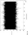
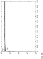
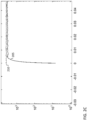
- FIGs. 2A - 2C show results from a simulation, in which an embodiment of the present disclosure was employed to perform DC balancing.
- the simulated raw data are sets of raw data words, each set including 31 six-bit pseudorandom raw data words.
- FIG. 2A shows the running disparity of the result of encoding the raw data, in accordance with some embodiments. It may be seen that, during the time interval simulated, the absolute value of the running disparity remains less than 30.
- FIGs. 2B and 2C depict the power spectrum 205 of the transmitted data, plotted along with the power spectrum of a random bit stream 210 for reference (with FIG. 2C depicting an enlarged view of a low-frequency portion of the power spectra of FIG. 2B ). It may be seen that at low frequencies the power spectrum is significantly reduced when DC balancing is performed.
- a disparity in a set of bits is defined as the difference between the number of ones and the number of zeros in the set; the disparity may equally we be defined as the difference between the number of zeros and the number of ones in the set.
- each raw data word may be encoded with the complement of the encoding key.
- the method may use the second-best encoding key (i.e., the encoding key which, when used to encode the raw data words, results in the second-lowest value of the absolute value of the running disparity), instead of the best encoding key.
- the encoding key may be selected based on multiple criteria, including a criterion for performing DC balancing. For example, a threshold (maximum permissible) disparity may be set, and for each packet, an encoding key may be selected that prevents the absolute value of the running disparity from exceeding the threshold, and that, within this constraint, minimizes the run length in the transmitted data. As another example, an encoding key may be selected that minimizes a weighted sum of (i) the run length and (ii) the absolute value of the running disparity.
- DC balancing may be performed in an analogous manner (e.g., by selecting an encoding key, from among a set of candidate encoding keys, that minimizes the absolute value of the running disparity), with an encoding key selected by a different method or using a different encoding method.
- FIG. 3 depicts a display, in accordance with some embodiments.
- the display may be a video display such as a computer monitor or any other such related display.
- the display includes a display panel (e.g., an organic light-emitting diode (OLED) display panel) 300 driven by a plurality of driver integrated circuits (ICs) 320.
- the driver ICs 320 may generate analog drive signals, for driving the pixels of the display, in response to digital data received from a timing controller (TCON) 310, which may send the serial data, encoded according to a method disclosed herein, to the driver ICs 320 over serial data links 330.
- the TCON 310 may include a processing circuit 340 configured to implement one or more of the methods disclosed herein.
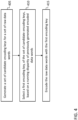
- FIG. 4 is a flow chart of a method.
- the method includes generating, at 405, a set of candidate encoding keys for a set of raw data words; selecting, at 410, a first encoding key, of the set of candidate encoding keys, based on a running disparity of previously generated encoded data words; and encoding, at 415, the raw data words with the first encoding key.
- the difference between A and B is A-B
- a difference between A and B is either A-B or B-A.
- a portion of something means “at least some of” the thing, and as such may mean less than all of, or all of, the thing.
- a portion of a thing includes the entire thing as a special case, i.e., the entire thing is an example of a portion of the thing.
- a second quantity is "within Y" of a first quantity X, it means that the second quantity is at least X-Y and the second quantity is at most X+Y.
- a second number is "within Y%" of a first number, it means that the second number is at least (1-Y/100) times the first number and the second number is at most (1+Y/100) times the first number.
- the term “or” should be interpreted as “and/or”, such that, for example, "A or B” means any one of "A” or "B” or “A and B”.
- processing circuit is used herein to mean any combination of hardware, firmware, and software, employed to process data or digital signals.
- Processing circuit hardware may include, for example, application specific integrated circuits (ASICs), general purpose or special purpose central processing units (CPUs), digital signal processors (DSPs), graphics processing units (GPUs), and programmable logic devices such as field programmable gate arrays (FPGAs).
- ASICs application specific integrated circuits
- CPUs general purpose or special purpose central processing units
- DSPs digital signal processors
- GPUs graphics processing units
- FPGAs programmable logic devices
- each function is performed either by hardware configured, i.e., hard-wired, to perform that function, or by more general-purpose hardware, such as a CPU, configured to execute instructions stored in a non-transitory storage medium.
- a processing circuit may be fabricated on a single printed circuit board (PCB) or distributed over several interconnected PCBs.
- a processing circuit may contain other processing circuits; for example, a processing circuit may include two processing circuits, an FPGA and a CPU, interconnected on a PCB.
- a method e.g., an adjustment
- a first quantity e.g., a first variable
- a second quantity e.g., a second variable
- the second quantity is an input to the method or influences the first quantity
- the second quantity may be an input (e.g., the only input, or one of several inputs) to a function that calculates the first quantity, or the first quantity may be equal to the second quantity, or the first quantity may be the same as (e.g., stored at the same location or locations in memory as) the second quantity.
- first, second, third, etc. may be used herein to describe various elements, components, regions, layers and/or sections, these elements, components, regions, layers and/or sections should not be limited by these terms. These terms are only used to distinguish one element, component, region, layer or section from another element, component, region, layer or section. Thus, a first element, component, region, layer or section discussed herein could be termed a second element, component, region, layer or section, without departing from the scope of the inventive concept.
- any numerical range recited herein is intended to include all sub-ranges of the same numerical precision subsumed within the recited range.
- a range of "1.0 to 10.0" or “between 1.0 and 10.0” is intended to include all subranges between (and including) the recited minimum value of 1.0 and the recited maximum value of 10.0, that is, having a minimum value equal to or greater than 1.0 and a maximum value equal to or less than 10.0, such as, for example, 2.4 to 7.6.
- a range described as "within 35% of 10" is intended to include all subranges between (and including) the recited minimum value of 6.5 (i.e., (1 - 35/100) times 10) and the recited maximum value of 13.5 (i.e., (1 + 35/100) times 10), that is, having a minimum value equal to or greater than 6.5 and a maximum value equal to or less than 13.5, such as, for example, 7.4 to 10.6.
- Any maximum numerical limitation recited herein is intended to include all lower numerical limitations subsumed therein and any minimum numerical limitation recited in this specification is intended to include all higher numerical limitations subsumed therein.
Landscapes
- Engineering & Computer Science (AREA)
- Theoretical Computer Science (AREA)
- Computer Networks & Wireless Communication (AREA)
- Signal Processing (AREA)
- Physics & Mathematics (AREA)
- Spectroscopy & Molecular Physics (AREA)
- Computer Hardware Design (AREA)
- General Physics & Mathematics (AREA)
- Compression, Expansion, Code Conversion, And Decoders (AREA)
- Dc Digital Transmission (AREA)
- Image Processing (AREA)
Abstract
Description
- One or more aspects of embodiments according to the present disclosure relate to data transmission, and more particularly to a system and method for DC balanced transition encoding.
- When serial data are transmitted from a transmitter to a receiver and the data include an embedded clock, transitions in the data may be employed for clock recovery in the receiver; as such, an absence of transitions during an extended interval of time may adversely impact the ability of the receiver to perform data recovery. Moreover, in AC-coupled data links it may be advantageous to limit the DC component of the serial data stream, to avoid unacceptable DC wander.
- It is with respect to this general technical environment that aspects of the present disclosure are related.
- According to an embodiment of the present disclosure, there is provided a method, including: generating a set of candidate encoding keys for a set of raw data words; selecting a first encoding key, of the set of candidate encoding keys, based on a first disparity contribution; and encoding the set of raw data words with the first encoding key, the first disparity contribution being a difference between the number of ones and the number of zeros in the result of encoding the set of raw data words with the first encoding key.
- In some embodiments, the selection of the first encoding key is further based on a running disparity of previously generated encoded data words.
- In some embodiments: the absolute value of the sum of: the running disparity of previously generated encoded data words and the first disparity contribution is less than the absolute value of the sum of: the running disparity of previously generated encoded data words and a second disparity contribution; and the second disparity contribution is a difference between the number of ones and the number of zeros in the result of encoding the set of raw data words with a second encoding key of the set of candidate encoding keys.
- In some embodiments, the method further includes calculating the first disparity contribution, wherein the calculating of the first disparity contribution includes: calculating a set of bit level disparities, each corresponding to a bit level of the raw data words; changing the sign of each bit level disparity corresponding to a one in the first encoding key, to form a set of polarity-adjusted bit level disparities; and summing: the polarity-adjusted bit level disparities; and a disparity of the first encoding key, wherein: the absolute value of the bit level disparity at each bit level is equal to the absolute value of the difference between the number of ones, at the bit level, in all of the raw data words, and the number of zeros at the bit level, in all of the raw data words; and the absolute value of the disparity of the first encoding key is equal to the absolute value of the difference between the number of ones of the first encoding key and the number of zeros of the first encoding key.
- In some embodiments, the calculating the set of bit level disparities comprises calculating of a first bit level disparity, of the set of bit level disparities, at a first bit level, and the calculating of the first bit level disparity, includes calculating the difference between twice the number of ones at the first bit level and the number of raw data words.
- In some embodiments, the result of encoding the set of raw data words with the first encoding key includes: the first encoding key; and the exclusive-OR of the first encoding key with each of the raw data words.
- In some embodiments, the result of encoding the set of raw data words with the first encoding key is a set of encoded data words having a maximum run length not exceeding a first threshold.
- In some embodiments, the result of encoding the set of raw data words with the first encoding key includes: the first encoding key; and the exclusive-OR of the first encoding key with each of the raw data words.
- In some embodiments, the result of encoding the set of raw data words with any one of the set of candidate encoding keys is a set of encoded data words having a maximum run length not exceeding the first threshold.
- In some embodiments, the absolute value of the first disparity contribution is less than the absolute value of a second disparity contribution; and the second disparity contribution is a difference between the number of ones and the number of zeros in the result of encoding the set of raw data words with a second encoding key of the set of candidate encoding keys.
- According to an embodiment of the present disclosure, there is provided a system, including: a processing circuit; and a memory connected to the processing circuit, the memory storing instructions that, when executed by the processing circuit, cause the system to perform a method, the method including: generating a set of candidate encoding keys for a set of raw data words; selecting a first encoding key, of the set of candidate encoding keys, based on a running disparity of previously generated encoded data words; and encoding the set of raw data words with the first encoding key.
- In some embodiments, the selection of the first encoding key is further based on a first disparity contribution, the first disparity contribution being a difference between the number of ones and the number of zeros in the result of encoding the set of raw data words with the first encoding key.
- In some embodiments: the absolute value of the sum of: the running disparity of previously generated encoded data words and the first disparity contribution is less than the absolute value of the sum of: the running disparity of previously generated encoded data words and a second disparity contribution; and the second disparity contribution is a difference between the number of ones and the number of zeros in the result of encoding the set of raw data words with a second encoding key of the set of candidate encoding keys.
- In some embodiments, the method further includes calculating the first disparity contribution, wherein the calculating of the first disparity contribution includes: calculating a set of bit level disparities, each corresponding to a bit level of the raw data words; changing the sign of each bit level disparity corresponding to a one in the first encoding key, to form a set of polarity-adjusted bit level disparities; and summing: the polarity-adjusted bit level disparities; and a disparity of the first encoding key, wherein: the absolute value of the bit level disparity at each bit level is equal to the absolute value of the difference between the number of ones, at the bit level, in all of the raw data words, and the number of zeros at the bit level, in all of the raw data words; and the absolute value of the disparity of the first encoding key is equal to the absolute value of the difference between the number of ones of the first encoding key and the number of zeros of the first encoding key.
- In some embodiments, the calculating the set of bit level disparities comprises calculating of a bit level disparity, of the set of bit level disparities, at the first bit level, and the calculating of the first bit level disparity, includes calculating the difference between twice the number of ones at the first bit level and the number of raw data words.
- In some embodiments, the result of encoding the set of raw data words with the first encoding key includes: the first encoding key; and the exclusive-OR of the first encoding key with each of the raw data words.
- In some embodiments, the result of encoding the set of raw data words with the first encoding key is a set of encoded data words having a maximum run length less than a first threshold.
- In some embodiments, the result of encoding the set of raw data words with the first encoding key includes: the first encoding key; and the exclusive-OR of the first encoding key with each of the raw data words.
- In some embodiments, the result of encoding the set of raw data words with any one of the set of candidate encoding keys is a set of encoded data words having a maximum run length less than the first threshold.
- According to an embodiment of the present disclosure, there is provided a display, including: a timing controller; and a driver integrated circuit, the timing controller including a processing circuit; and a memory connected to the processing circuit, the memory storing instructions that, when executed by the processing circuit, cause the timing controller to perform a method, the method including: generating a set of candidate encoding keys for a set of raw data words; selecting a first encoding key, of the set of candidate encoding keys, based on a running disparity of previously generated encoded data words; and encoding the set of raw data words with the first encoding key.
- At least some of the above and other features of the invention are set out in the claims.
- These and other features and advantages of the present disclosure will be appreciated and understood with reference to the specification, claims, and appended drawings wherein:
-
FIG. 1 is an illustration of a serial bit sequence, according to an embodiment of the present disclosure; -
FIG. 2A is a graph of a simulation result, according to an embodiment of the present disclosure; -
FIG. 2B is a graph of a simulation result, according to an embodiment of the present disclosure; -
FIG. 2C is a graph of a simulation result, according to an embodiment of the present disclosure; -
FIG. 3 is a block diagram of a display, according to an embodiment of the present disclosure; and -
FIG. 4 is a flow chart of a method, according to an embodiment of the present disclosure. - The detailed description set forth below in connection with the appended drawings is intended as a description of example embodiments of a system and method for DC balanced transition encoding provided in accordance with the present disclosure and is not intended to represent the only forms in which the present disclosure may be constructed or utilized. The description sets forth the features of the present disclosure in connection with the illustrated embodiments. It is to be understood, however, that the same or equivalent functions and structures may be accomplished by different embodiments that are also intended to be encompassed within the scope of the disclosure. As denoted elsewhere herein, like element numbers are intended to indicate like elements or features.
- In operation, a serial transmitter may receive a plurality (e.g., a set or a sequence) of raw data words to be transmitted to a receiver, and the transmitter may process, e.g., encode, the raw data words and transmit the encoded data words to the receiver. Such encoding may be used, for example, to limit the run length of the transmitted data, where the "run length" is the length of an interval without transitions, i.e., the length of a run of consecutive zeros or ones.
FIG. 1 shows an example of a portion of a transmitteddata stream 105. In the portion illustrated, thelongest run 110 has a length of three symbols, the two second-longest runs 115 each have a length of 2 symbols, and each of theremaining runs 120 has a length of one symbol. - The encoding performed by the transmitter may have the effect of ensuring (e.g., guaranteeing) that the longest run length does not exceed a certain threshold, and thereby to reduce the risk that a long run will compromise the ability of the receiver to perform clock recovery. The encoding method may, for example, involve encoding the raw data, one set (or "packet") of raw data words at a time, with an encoding key, and transmitting, to the receiver, the encoding key and the encoded data. The receiver may then use the received encoding key to decode the received encoded data, to recover the raw data. Such an encoding method may result in encoded data having a non-zero DC value, i.e., it may result in encoded data in which the number of zeros is consistently greater than, or consistently less than, the number of ones. If the link connecting the transmitter to the receiver is AC-coupled, this characteristic in the transmitted data may result in DC wander at the receiver.
- As such, in some embodiments, the encoding is done in a manner that suppresses the DC component of the transmitted data. For example, the encoding may proceed as follows, for a packet of N p-bit raw data words (e.g., N six-bit raw data words, which may be denoted { x1, x2, ... , xN }).
- An encoding key K, having the same length (p) as each of the raw data words (e.g., 6 bits) and being different from (i) each of the raw data words and (ii) the complement of each of the raw data words, may then be selected. Because there are 2p (e.g., 64, for p=6) possible p-bit words, selecting N to be less than 2(p-1) (e.g., 31) will ensure that at least two such encoding keys K exist; for any such encoding key K the complement is also a viable (or "valid") encoding key. The encoded packet may then be formed as (i) the exclusive OR of each of the raw data words with the selected encoding key, and (ii) the encoding key, which may, for example, be appended to the end of the packet (or inserted at the beginning of the packet, or at any other position in the encoded packet at which the receiver expects to find the encoding key). For example, the result of encoding the set of raw data words may be { K, x1^K, x2^K, ... , x31^K } where the caret ("^") denotes the bit-wise exclusive-OR of two words. Such an encoded packet may have the characteristic that the maximum run length does not exceed a threshold, where the threshold is equal to 2(p-1).
- To suppress the DC component of data encoded in this manner, the encoding key may be selected so as to minimize the absolute value of a running disparity of the encoded data (where the running disparity may be the difference between the total number of ones transmitted and the total number of zeros transmitted). For example, if, for the nth packet, the set of m (viable) candidate encoding keys is { K1, K2, ..., Km }, the result of encoding the set of raw data words with each of the encoding keys may be calculated, and, for each of the candidate encoding keys, the effect that selecting the key would have on the running disparity of the transmitted data may be calculated, and the key that results in the running disparity having the smallest absolute value may be used.
- For example, for each possible encoded packet (each encoded packet being the result of encoding the set of raw data words with a respective one of the candidate encoding keys), the sum of all the ones in the encoded packet minus the sum of all zeros in the packet may be calculated; this sum may be referred to as disparity contribution D(Ki) for the ith candidate encoding key.
- The running disparity (RD) over all previously transmitted packets, e.g.,
packets 0 to n-1, may be equal to the number of ones transmitted inpackets 0 to n-1 minus the number of zeros transmitted inpackets 0 to n-1. The quantity BEST_RD = minimum abs( RD(n-1) + D(Ki) ) over all candidate keys Ki, (which is the minimum running disparity achievable after transmission of the nth packet), where each Ki is one of the candidate encoding keys { K1, K2, ..., Km }, may be found and the candidate key corresponding to this quantity, called K*, may then be used to encode the raw data, to generate the nth encoded packet. The running disparity may then be updated, by setting RD(n) = RD(n-1) + D(K*), for use in selecting an encoding key for the next (i.e., the n+1th) packet. - In some embodiments, the absolute value of the disparity contribution D(Ki) may be minimized. The disparity contribution having the minimum achievable absolute value at the nth packet may be found and the candidate key corresponding to this quantity may then be used to encode the raw data, to generate the nth encoded packet.
- In some embodiments, the disparity contribution D(Ki) may be calculated as follows. First, the number of ones in each bit-level may be counted in all of the raw data words; this number, at the jth bit level, may be referred to as sum1s[j].
- For example, for six-bit words, six sums may be computed, for
bit levels

- The sign of each bit level disparity corresponding to a one in the encoding key Ki may then be changed to form a set of polarity-adjusted bit level disparities (which, at the jth bit level, may be referred to as pdiff10[j]). Finally, the disparity contribution D(Ki) may be calculated by summing the polarity-adjusted bit level disparities and a disparity of the encoding key:

-
FIGs. 2A - 2C show results from a simulation, in which an embodiment of the present disclosure was employed to perform DC balancing. The simulated raw data are sets of raw data words, each set including 31 six-bit pseudorandom raw data words.FIG. 2A shows the running disparity of the result of encoding the raw data, in accordance with some embodiments. It may be seen that, during the time interval simulated, the absolute value of the running disparity remains less than 30. -
FIGs. 2B and2C depict thepower spectrum 205 of the transmitted data, plotted along with the power spectrum of arandom bit stream 210 for reference (withFIG. 2C depicting an enlarged view of a low-frequency portion of the power spectra ofFIG. 2B ). It may be seen that at low frequencies the power spectrum is significantly reduced when DC balancing is performed. - A number of variants of the methods described above may be employed to have a similar or identical effect. For example, in the examples described above, a disparity in a set of bits is defined as the difference between the number of ones and the number of zeros in the set; the disparity may equally we be defined as the difference between the number of zeros and the number of ones in the set. As another example, each bit-level disparity may be calculated as diff10[j] = 31 - 2 x sumOs[j], where sum0s[j] is a count of the number of zeros in the raw data words at the jth bit level. As another example, instead of encoding each raw data word as the exclusive-OR of the raw data word with the encoding key, each raw data word may be encoded with the complement of the encoding key. As another example, if there are more than two candidate encoding keys (e.g., if there are four candidate encoding keys), then the method may use the second-best encoding key (i.e., the encoding key which, when used to encode the raw data words, results in the second-lowest value of the absolute value of the running disparity), instead of the best encoding key.
- In some embodiments, the encoding key may be selected based on multiple criteria, including a criterion for performing DC balancing. For example, a threshold (maximum permissible) disparity may be set, and for each packet, an encoding key may be selected that prevents the absolute value of the running disparity from exceeding the threshold, and that, within this constraint, minimizes the run length in the transmitted data. As another example, an encoding key may be selected that minimizes a weighted sum of (i) the run length and (ii) the absolute value of the running disparity.
- In some embodiments, DC balancing may be performed in an analogous manner (e.g., by selecting an encoding key, from among a set of candidate encoding keys, that minimizes the absolute value of the running disparity), with an encoding key selected by a different method or using a different encoding method.
-
FIG. 3 depicts a display, in accordance with some embodiments. For example, the display may be a video display such as a computer monitor or any other such related display. The display includes a display panel (e.g., an organic light-emitting diode (OLED) display panel) 300 driven by a plurality of driver integrated circuits (ICs) 320. Thedriver ICs 320 may generate analog drive signals, for driving the pixels of the display, in response to digital data received from a timing controller (TCON) 310, which may send the serial data, encoded according to a method disclosed herein, to thedriver ICs 320 overserial data links 330. TheTCON 310 may include aprocessing circuit 340 configured to implement one or more of the methods disclosed herein. -
FIG. 4 is a flow chart of a method. In some embodiments, the method includes generating, at 405, a set of candidate encoding keys for a set of raw data words; selecting, at 410, a first encoding key, of the set of candidate encoding keys, based on a running disparity of previously generated encoded data words; and encoding, at 415, the raw data words with the first encoding key. - As used herein, for two quantities A and B, "the difference" between A and B is A-B, and "a difference" between A and B is either A-B or B-A. As used herein, "a portion of" something means "at least some of" the thing, and as such may mean less than all of, or all of, the thing. As such, "a portion of" a thing includes the entire thing as a special case, i.e., the entire thing is an example of a portion of the thing. As used herein, when a second quantity is "within Y" of a first quantity X, it means that the second quantity is at least X-Y and the second quantity is at most X+Y. As used herein, when a second number is "within Y%" of a first number, it means that the second number is at least (1-Y/100) times the first number and the second number is at most (1+Y/100) times the first number. As used herein, the term "or" should be interpreted as "and/or", such that, for example, "A or B" means any one of "A" or "B" or "A and B".
- The term "processing circuit" is used herein to mean any combination of hardware, firmware, and software, employed to process data or digital signals. Processing circuit hardware may include, for example, application specific integrated circuits (ASICs), general purpose or special purpose central processing units (CPUs), digital signal processors (DSPs), graphics processing units (GPUs), and programmable logic devices such as field programmable gate arrays (FPGAs). In a processing circuit, as used herein, each function is performed either by hardware configured, i.e., hard-wired, to perform that function, or by more general-purpose hardware, such as a CPU, configured to execute instructions stored in a non-transitory storage medium. A processing circuit may be fabricated on a single printed circuit board (PCB) or distributed over several interconnected PCBs. A processing circuit may contain other processing circuits; for example, a processing circuit may include two processing circuits, an FPGA and a CPU, interconnected on a PCB.
- As used herein, when a method (e.g., an adjustment) or a first quantity (e.g., a first variable) is referred to as being "based on" a second quantity (e.g., a second variable) it means that the second quantity is an input to the method or influences the first quantity, e.g., the second quantity may be an input (e.g., the only input, or one of several inputs) to a function that calculates the first quantity, or the first quantity may be equal to the second quantity, or the first quantity may be the same as (e.g., stored at the same location or locations in memory as) the second quantity.
- It will be understood that, although the terms "first", "second", "third", etc., may be used herein to describe various elements, components, regions, layers and/or sections, these elements, components, regions, layers and/or sections should not be limited by these terms. These terms are only used to distinguish one element, component, region, layer or section from another element, component, region, layer or section. Thus, a first element, component, region, layer or section discussed herein could be termed a second element, component, region, layer or section, without departing from the scope of the inventive concept.
- The terminology used herein is for the purpose of describing particular embodiments only and is not intended to be limiting of the inventive concept. As used herein, the terms "substantially," "about," and similar terms are used as terms of approximation and not as terms of degree, and are intended to account for the inherent deviations in measured or calculated values that would be recognized by those of ordinary skill in the art.
- As used herein, the singular forms "a" and "an" are intended to include the plural forms as well, unless the context clearly indicates otherwise. It will be further understood that the terms "comprises" and/or "comprising", when used in this specification, specify the presence of stated features, integers, steps, operations, elements, and/or components, but do not preclude the presence or addition of one or more other features, integers, steps, operations, elements, components, and/or groups thereof. As used herein, the term "and/or" includes any and all combinations of one or more of the associated listed items. Expressions such as "at least one of," when preceding a list of elements, modify the entire list of elements and do not modify the individual elements of the list. Further, the use of "may" when describing embodiments of the inventive concept refers to "one or more embodiments of the present disclosure". Also, the term "exemplary" is intended to refer to an example or illustration. As used herein, the terms "use," "using," and "used" may be considered synonymous with the terms "utilize," "utilizing," and "utilized," respectively.
- Any numerical range recited herein is intended to include all sub-ranges of the same numerical precision subsumed within the recited range. For example, a range of "1.0 to 10.0" or "between 1.0 and 10.0" is intended to include all subranges between (and including) the recited minimum value of 1.0 and the recited maximum value of 10.0, that is, having a minimum value equal to or greater than 1.0 and a maximum value equal to or less than 10.0, such as, for example, 2.4 to 7.6. Similarly, a range described as "within 35% of 10" is intended to include all subranges between (and including) the recited minimum value of 6.5 (i.e., (1 - 35/100) times 10) and the recited maximum value of 13.5 (i.e., (1 + 35/100) times 10), that is, having a minimum value equal to or greater than 6.5 and a maximum value equal to or less than 13.5, such as, for example, 7.4 to 10.6. Any maximum numerical limitation recited herein is intended to include all lower numerical limitations subsumed therein and any minimum numerical limitation recited in this specification is intended to include all higher numerical limitations subsumed therein.
- Although exemplary embodiments of a system and method for DC balanced transition encoding have been specifically described and illustrated herein, many modifications and variations will be apparent to those skilled in the art. Accordingly, it is to be understood that a system and method for DC balanced transition encoding constructed according to principles of this disclosure may be embodied other than as specifically described herein. The invention is also defined in the following claims, and equivalents thereof.
Claims (16)
- A method, comprising:generating a set of candidate encoding keys for a set of raw data words;selecting a first encoding key, of the set of candidate encoding keys, based on a first disparity contribution; andencoding the set of raw data words with the first encoding key,the first disparity contribution being a difference between the number of ones and the number of zeros in the result of encoding the set of raw data words with the first encoding key.
- The method of claim 1, wherein the selection of the first encoding key is further based on a running disparity of previously generated encoded data words.
- The method of claim 2, wherein:the absolute value of the sum of:the running disparity of previously generated encoded data words andthe first disparity contribution is less than the absolute value of the sum of:the running disparity of previously generated encoded data words anda second disparity contribution; andthe second disparity contribution is a difference between the number of ones and the number of zeros in the result of encoding the set of raw data words with a second encoding key of the set of candidate encoding keys.
- The method of claim 1, wherein the absolute value of the first disparity contribution is less than the absolute value of a second disparity contribution; and
the second disparity contribution is a difference between the number of ones and the number of zeros in the result of encoding the set of raw data words with a second encoding key of the set of candidate encoding keys. - The method of any preceding claim, further comprising calculating the first disparity contribution, wherein the calculating of the first disparity contribution comprises:calculating a set of bit level disparities, each corresponding to a bit level of the raw data words;changing the sign of each bit level disparity corresponding to a one in the first encoding key, to form a set of polarity-adjusted bit level disparities; andsumming:the polarity-adjusted bit level disparities; anda disparity of the first encoding key,wherein:the absolute value of the bit level disparity at each bit level is equal to the absolute value of the difference betweenthe number of ones, at the bit level, in all of the raw data words, andthe number of zeros at the bit level, in all of the raw data words; andthe absolute value of the disparity of the first encoding key is equal to the absolute value of the difference between the number of ones of the first encoding key and the number of zeros of the first encoding key.
- The method of claim 5, wherein the calculating the set of bit level disparities comprises calculating of a first bit level disparity, of the set of bit level disparities, at a first bit level, and
the calculating of the first bit level disparity, comprises calculating the difference betweentwice the number of ones at the first bit level andthe number of raw data words. - The method of any preceding claim, wherein the result of encoding the set of raw data words with the first encoding key comprises:the first encoding key; andthe exclusive-OR of the first encoding key with each of the raw data words.
- The method of any preceding claim, wherein the result of encoding the set of raw data words with the first encoding key is a set of encoded data words having a maximum run length not exceeding a first threshold, and optionally wherein the result of encoding the set of raw data words with any one of the set of candidate encoding keys is a set of encoded data words having a maximum run length not exceeding the first threshold.
- A system, comprising:a processing circuit; anda memory connected to the processing circuit,the memory storing instructions that, when executed by the processing circuit, cause the system to perform a method, the method comprising:generating a set of candidate encoding keys for a set of raw data words;selecting a first encoding key, of the set of candidate encoding keys, based on a running disparity of previously generated encoded data words; andencoding the set of raw data words with the first encoding key.
- The system of claim 9, wherein the selection of the first encoding key is further based on a first disparity contribution, the first disparity contribution being a difference between the number of ones and the number of zeros in the result of encoding the set of raw data words with the first encoding key.
- The system of claim 10, wherein:the absolute value of the sum of:the running disparity of previously generated encoded data words andthe first disparity contribution is less than the absolute value of the sum of:the running disparity of previously generated encoded data words anda second disparity contribution; andthe second disparity contribution is a difference between the number of ones and the number of zeros in the result of encoding the set of raw data words with a second encoding key of the set of candidate encoding keys.
- The system of claim 10 or claim 11, wherein the method further comprises calculating the first disparity contribution, wherein the calculating of the first disparity contribution comprises:calculating a set of bit level disparities, each corresponding to a bit level of the raw data words;changing the sign of each bit level disparity corresponding to a one in the first encoding key, to form a set of polarity-adjusted bit level disparities; andsumming:the polarity-adjusted bit level disparities; anda disparity of the first encoding key,wherein:the absolute value of the bit level disparity at each bit level is equal to the absolute value of the difference betweenthe number of ones, at the bit level, in all of the raw data words, andthe number of zeros at the bit level, in all of the raw data words; andthe absolute value of the disparity of the first encoding key is equal to the absolute value of the difference between the number of ones of the first encoding key and the number of zeros of the first encoding key.
- The system of claim 12, wherein the calculating the set of bit level disparities comprises calculating of a bit level disparity, of the set of bit level disparities, at the first bit level, and
the calculating of the first bit level disparity, comprises calculating the difference between twice the number of ones at the first bit level and the number of raw data words. - The system of any one of claims 9 - 13, wherein the result of encoding the set of raw data words with the first encoding key comprises:the first encoding key; andthe exclusive-OR of the first encoding key with each of the raw data words.
- The system of any one of claims 9 - 14, wherein the result of encoding the set of raw data words with the first encoding key is a set of encoded data words having a maximum run length less than a first threshold, and optionally wherein the result of encoding the set of raw data words with any one of the set of candidate encoding keys is a set of encoded data words having a maximum run length less than the first threshold.
- A display, comprising:a timing controller; anda driver integrated circuit, wherein the timing controller is a system according to any one of claims 9 - 15.
Applications Claiming Priority (2)
| Application Number | Priority Date | Filing Date | Title |
|---|---|---|---|
| US202163276178P | 2021-11-05 | 2021-11-05 | |
| US17/831,354 US12081376B2 (en) | 2021-11-05 | 2022-06-02 | DC balanced transition encoding |
Publications (2)
| Publication Number | Publication Date |
|---|---|
| EP4178115A1 true EP4178115A1 (en) | 2023-05-10 |
| EP4178115B1 EP4178115B1 (en) | 2025-10-15 |
Family
ID=84361585
Family Applications (1)
| Application Number | Title | Priority Date | Filing Date |
|---|---|---|---|
| EP22205488.4A Active EP4178115B1 (en) | 2021-11-05 | 2022-11-04 | Dc balanced transition encoding |
Country Status (6)
| Country | Link |
|---|---|
| US (2) | US12081376B2 (en) |
| EP (1) | EP4178115B1 (en) |
| JP (1) | JP7524274B2 (en) |
| KR (1) | KR20230066259A (en) |
| CN (1) | CN116092424A (en) |
| TW (1) | TW202341670A (en) |
Families Citing this family (2)
| Publication number | Priority date | Publication date | Assignee | Title |
|---|---|---|---|---|
| US12081376B2 (en) * | 2021-11-05 | 2024-09-03 | Samsung Display Co., Ltd. | DC balanced transition encoding |
| CN119446052B (en) * | 2025-01-07 | 2025-06-17 | 杭州视芯科技股份有限公司 | Communication control method of communication system and communication system |
Citations (3)
| Publication number | Priority date | Publication date | Assignee | Title |
|---|---|---|---|---|
| EP2892156A2 (en) * | 2013-12-27 | 2015-07-08 | Altera Corporation | Apparatus for improved encoding and associated methods |
| US20160072610A1 (en) * | 2014-09-09 | 2016-03-10 | Stmicroelectronics (Grenoble 2) Sas | Methods for transmission and reception of a serial signal and corresponding devices |
| WO2021039098A1 (en) * | 2019-08-30 | 2021-03-04 | ソニーセミコンダクタソリューションズ株式会社 | Encoding device, encoding method, decoding device, decoding method, and program |
Family Cites Families (61)
| Publication number | Priority date | Publication date | Assignee | Title |
|---|---|---|---|---|
| JPH0758916B2 (en) | 1985-07-30 | 1995-06-21 | キヤノン株式会社 | Data transmission device |
| US5229769A (en) * | 1992-02-21 | 1993-07-20 | Advanced Micro Devices, Inc. | Method and circuit for performing running disparity measurements |
| US5162791A (en) | 1989-10-02 | 1992-11-10 | Codenoll Technology Corporation | Collision detection using code rule violations of the manchester code |
| US5304996A (en) | 1992-02-21 | 1994-04-19 | Advanced Micro Devices, Inc. | 8B/10B encoder providing one of pair of noncomplementary, opposite disparity codes responsive to running disparity and selected commands |
| US5495287A (en) * | 1992-02-26 | 1996-02-27 | Hitachi, Ltd. | Multiple-tone display system |
| CA2157759A1 (en) * | 1993-03-10 | 1994-09-15 | Michael Seward Sutton | Enhanced one way radio seven bit data network |
| JPH09501788A (en) | 1994-03-09 | 1997-02-18 | フィリップス エレクトロニクス ネムローゼ フェンノートシャップ | Transmission / reception device, transmission / reception method, record carrier obtained by this transmission / reception method or transmission device |
| US5689278A (en) * | 1995-04-03 | 1997-11-18 | Motorola | Display control method |
| EP0791249B1 (en) | 1995-09-08 | 2002-07-03 | Koninklijke Philips Electronics N.V. | Transmitter and receiver apparatus, method for transmitting and method for receiving and record carrier obtained by the method or the transmitter apparatus |
| US5999571A (en) | 1995-10-05 | 1999-12-07 | Silicon Image, Inc. | Transition-controlled digital encoding and signal transmission system |
| US5825824A (en) | 1995-10-05 | 1998-10-20 | Silicon Image, Inc. | DC-balanced and transition-controlled encoding method and apparatus |
| US6067065A (en) * | 1998-05-08 | 2000-05-23 | Aurora Systems, Inc. | Method for modulating a multiplexed pixel display |
| US6970522B1 (en) | 1999-04-16 | 2005-11-29 | Hewlett-Packard Development Company, L.P. | Data retrieval |
| CN1305220C (en) | 2001-07-09 | 2007-03-14 | 希捷科技有限公司 | Methoa and apparatus for suppressing low frequency content in digital data |
| US6920604B2 (en) | 2002-04-08 | 2005-07-19 | Galazar Networks, Inc. | Systems and methods for high speed serial encoding and decoding for data and control interfaces |
| JP2003345306A (en) * | 2002-05-23 | 2003-12-03 | Sanyo Electric Co Ltd | Display device |
| US7535836B2 (en) | 2003-02-12 | 2009-05-19 | Broadcom Corporation | Method and system to provide word-level flow control using spare link bandwidth |
| US6747580B1 (en) * | 2003-06-12 | 2004-06-08 | Silicon Image, Inc. | Method and apparatus for encoding or decoding data in accordance with an NB/(N+1)B block code, and method for determining such a block code |
| US7138930B1 (en) * | 2003-09-17 | 2006-11-21 | Cypress Semiconductor Corporation | Multiple byte data path encoding/decoding device and method |
| JP5011116B2 (en) | 2004-10-26 | 2012-08-29 | エージェンシー フォー サイエンス,テクノロジー アンド リサーチ | Method and system for performing information encoding and decoding using modulation constraints and error control |
| US20060126751A1 (en) | 2004-12-10 | 2006-06-15 | Anthony Bessios | Technique for disparity bounding coding in a multi-level signaling system |
| US7064683B1 (en) * | 2005-01-19 | 2006-06-20 | Seagate Technology Llc | Speed optimized encoder with running disparity constraint |
| CN101341658B (en) | 2005-12-19 | 2013-03-27 | 索尼公司 | A coder and a method of coding for codes with a parity-complementary word assignment having a constraint of d='1', r='2' |
| TWI297479B (en) * | 2006-06-13 | 2008-06-01 | Novatek Microelectronics Corp | Method for display image frame and display apparatus using the same |
| US8275080B2 (en) | 2006-11-17 | 2012-09-25 | Comtech Mobile Datacom Corporation | Self-supporting simplex packets |
| US20080275662A1 (en) | 2007-05-01 | 2008-11-06 | Vladimir Dmitriev-Zdorov | Generating transmission-code compliant test sequences |
| US20080303767A1 (en) * | 2007-06-01 | 2008-12-11 | National Semiconductor Corporation | Video display driver with gamma control |
| US8155215B2 (en) * | 2007-06-29 | 2012-04-10 | Advantest Corporation | Transmission system, transmitter, receiver, and transmission method |
| JP2010258985A (en) | 2009-04-28 | 2010-11-11 | Sony Corp | Signal processing apparatus and error correction method |
| US8659450B1 (en) * | 2011-04-21 | 2014-02-25 | Sk Hynix Memory Solutions Inc. | MTR and RLL code design and encoder and decoder |
| US9304857B2 (en) * | 2011-12-12 | 2016-04-05 | Cleversafe, Inc. | Retrieving data from a distributed storage network |
| US9297321B2 (en) * | 2011-12-13 | 2016-03-29 | Woodward, Inc. | Flexible crank angle position sensing |
| TWI574242B (en) * | 2012-04-02 | 2017-03-11 | 緯創資通股份有限公司 | Display device, display method, and encoding method |
| US9184912B2 (en) * | 2012-04-17 | 2015-11-10 | The Boeing Company | Secure quantum authentication system |
| JP5293860B1 (en) | 2012-05-16 | 2013-09-18 | 富士ゼロックス株式会社 | Serial communication system, image forming system, and transmission apparatus |
| US8891520B2 (en) | 2012-06-28 | 2014-11-18 | Alcatel Lucent | Scaling redundancy elimination middleboxes |
| US9942063B2 (en) * | 2012-10-26 | 2018-04-10 | Altera Corporation | Apparatus for improved encoding and associated methods |
| CN104995612B (en) * | 2013-01-17 | 2020-01-03 | 康杜实验室公司 | Inter-chip communication method and system with low synchronous switching noise |
| KR102025120B1 (en) * | 2013-05-24 | 2019-09-26 | 삼성디스플레이 주식회사 | A compensation unit and organic light emitting display device including the same |
| US10700856B2 (en) * | 2013-11-19 | 2020-06-30 | Network-1 Technologies, Inc. | Key derivation for a module using an embedded universal integrated circuit card |
| US10028277B2 (en) * | 2013-11-20 | 2018-07-17 | Cyborg Inc. | Variable frequency data transmission |
| US8941513B1 (en) * | 2013-11-20 | 2015-01-27 | Nicolas Thomas Mathieu Dupont | Variable frequency data transmission |
| KR102108380B1 (en) * | 2014-02-04 | 2020-05-08 | 삼성전자주식회사 | Interface circuit operating to recover transmitted data error |
| KR102278396B1 (en) * | 2014-07-11 | 2021-07-19 | 삼성디스플레이 주식회사 | Method of driving display panel and display apparatus for performing the same |
| KR102335113B1 (en) * | 2014-12-22 | 2021-12-03 | 삼성디스플레이 주식회사 | Display device and driving method thereof |
| KR102325675B1 (en) * | 2014-12-29 | 2021-11-12 | 삼성디스플레이 주식회사 | Organic Light Emitting Display Device |
| CN104851406B (en) * | 2015-06-10 | 2018-09-11 | 京东方科技集团股份有限公司 | A kind of method for displaying image, device and triangular arrangement show equipment |
| US10110343B2 (en) * | 2016-06-29 | 2018-10-23 | Mapper Lithography Ip B.V. | Method and encoding device for encoding a sequence of m-bit pattern words and outputting a frame comprising corresponding n-bit symbols |
| US9887707B2 (en) * | 2016-06-30 | 2018-02-06 | Mapper Lithography Ip B.V. | Method and device for generating a decoded and synchronized output |
| CN106097962B (en) * | 2016-08-19 | 2018-09-07 | 京东方科技集团股份有限公司 | Display base plate, display equipment and regional compensation method |
| KR20180092502A (en) * | 2017-02-09 | 2018-08-20 | 삼성전자주식회사 | Display controller and display driving apparatus including the same |
| US10715177B2 (en) * | 2017-06-20 | 2020-07-14 | Samsung Electronics Co., Ltd. | Lossy compression drive |
| CN111279422B (en) | 2017-10-25 | 2023-12-22 | 深圳华大生命科学研究院 | Encoding/decoding method, encoding/decoder and storage method and device |
| WO2019209246A1 (en) * | 2018-04-23 | 2019-10-31 | Hewlett-Packard Development Company, L.P. | Reflection and inversion invariant codes |
| JP2022107067A (en) | 2019-03-29 | 2022-07-21 | ローム株式会社 | Encoding circuit and semiconductor device, encoding method, data transmission system, and decoding circuit |
| US11146430B1 (en) | 2020-05-14 | 2021-10-12 | Seoul National University R&Db Foundation | DC-balanced, transition-controlled, scalable encoding method and apparatus for multi-level signaling |
| KR102865072B1 (en) * | 2021-06-14 | 2025-09-29 | 삼성디스플레이 주식회사 | Transceiver device, driving method thereof, and display system including the same |
| US20250284393A1 (en) * | 2021-08-17 | 2025-09-11 | AtomBeam Technologies Inc. | System and Method for Compaction of Floating-Point Numbers Within a Dataset with Metadata Tagging |
| US11764805B2 (en) * | 2021-10-06 | 2023-09-19 | Samsung Display Co., Ltd. | System and method for transition encoding with reduced error propagation |
| US12081376B2 (en) * | 2021-11-05 | 2024-09-03 | Samsung Display Co., Ltd. | DC balanced transition encoding |
| US12244686B2 (en) * | 2021-11-23 | 2025-03-04 | Samsung Electronics Co., Ltd. | Image sensor, image processing system having the same and operating method of the same |
-
2022
- 2022-06-02 US US17/831,354 patent/US12081376B2/en active Active
- 2022-11-01 JP JP2022175674A patent/JP7524274B2/en active Active
- 2022-11-04 KR KR1020220146183A patent/KR20230066259A/en active Pending
- 2022-11-04 EP EP22205488.4A patent/EP4178115B1/en active Active
- 2022-11-07 CN CN202211387127.4A patent/CN116092424A/en active Pending
- 2022-11-07 TW TW111142463A patent/TW202341670A/en unknown
-
2024
- 2024-08-30 US US18/821,891 patent/US20240422034A1/en active Pending
Patent Citations (3)
| Publication number | Priority date | Publication date | Assignee | Title |
|---|---|---|---|---|
| EP2892156A2 (en) * | 2013-12-27 | 2015-07-08 | Altera Corporation | Apparatus for improved encoding and associated methods |
| US20160072610A1 (en) * | 2014-09-09 | 2016-03-10 | Stmicroelectronics (Grenoble 2) Sas | Methods for transmission and reception of a serial signal and corresponding devices |
| WO2021039098A1 (en) * | 2019-08-30 | 2021-03-04 | ソニーセミコンダクタソリューションズ株式会社 | Encoding device, encoding method, decoding device, decoding method, and program |
Non-Patent Citations (2)
| Title |
|---|
| ANONYMOUS: "Constant-weight code", WIKIPEDIA, 22 September 2021 (2021-09-22), pages 1 - 3, XP093029761, Retrieved from the Internet <URL:https://en.wikipedia.org/w/index.php?title=Constant-weight_code&oldid=1045733408> [retrieved on 20230307] * |
| ANONYMOUS: "Paired disparity code", WIKIPEDIA, 6 June 2021 (2021-06-06), pages 1 - 1, XP093029760, Retrieved from the Internet <URL:https://en.wikipedia.org/w/index.php?title=Paired_disparity_code&oldid=1027088253> [retrieved on 20230307] * |
Also Published As
| Publication number | Publication date |
|---|---|
| JP2023070128A (en) | 2023-05-18 |
| US12081376B2 (en) | 2024-09-03 |
| KR20230066259A (en) | 2023-05-15 |
| JP7524274B2 (en) | 2024-07-29 |
| US20240422034A1 (en) | 2024-12-19 |
| US20230146120A1 (en) | 2023-05-11 |
| EP4178115B1 (en) | 2025-10-15 |
| CN116092424A (en) | 2023-05-09 |
| TW202341670A (en) | 2023-10-16 |
Similar Documents
| Publication | Publication Date | Title |
|---|---|---|
| US20240422034A1 (en) | Dc balanced transition encoding | |
| US7142612B2 (en) | Method and apparatus for multi-level signaling | |
| EP1064728B1 (en) | Technique for finding a starting state for a convolutional feedback encoder | |
| US20110310992A1 (en) | Systems, methods, and computer readable media for fractional pre-emphasis of multi-mode interconnect | |
| EP1624582A2 (en) | Apparatus and method for channel coding in mobile communication system | |
| US20030093752A1 (en) | System and method for generating cyclic redundancy check | |
| KR20040085545A (en) | Apparatus for decoding error correction doe in communication system and method thereof | |
| CN105515727A (en) | Apparatus for improved encoding and associated methods | |
| CN103795493B (en) | Device and correlating method for improving coding | |
| US10305631B1 (en) | System and method for frame synchronization | |
| CN107094050B (en) | Apparatus and method for processing digital signals | |
| CN111130562B (en) | CRC parallel computing method and system | |
| EP4142229A1 (en) | System and method for transition encoding with flexible word-size | |
| EP1694014A2 (en) | Application of a meta-viterbi algorithm for communication systems without intersymbol interference | |
| US7225391B1 (en) | Method and apparatus for parallel computation of linear block codes | |
| EP4283936A1 (en) | System and method for configuring serial receiver | |
| KR102510035B1 (en) | Method, system and display for transmitting input stream of data across serial link | |
| JP2005268910A (en) | Data receiver | |
| JP4436315B2 (en) | Convolutional encoder, communication apparatus, and convolutional encoding method | |
| US6941506B2 (en) | Switching circuit for decoder | |
| CN117135014A (en) | Displays and systems and methods for configuring serial receivers | |
| US7929572B2 (en) | Code division multiplex signal transmitter and code division multiplexing method with amplifying circuits reduced in number | |
| US20240028299A1 (en) | Mac operator related to circuit area | |
| RU2465632C1 (en) | Method of transmitting digital information through parallel highway | |
| JP2006508600A (en) | Communication law |
Legal Events
| Date | Code | Title | Description |
|---|---|---|---|
| PUAI | Public reference made under article 153(3) epc to a published international application that has entered the european phase |
Free format text: ORIGINAL CODE: 0009012 |
|
| STAA | Information on the status of an ep patent application or granted ep patent |
Free format text: STATUS: THE APPLICATION HAS BEEN PUBLISHED |
|
| AK | Designated contracting states |
Kind code of ref document: A1 Designated state(s): AL AT BE BG CH CY CZ DE DK EE ES FI FR GB GR HR HU IE IS IT LI LT LU LV MC ME MK MT NL NO PL PT RO RS SE SI SK SM TR |
|
| P01 | Opt-out of the competence of the unified patent court (upc) registered |
Effective date: 20230711 |
|
| STAA | Information on the status of an ep patent application or granted ep patent |
Free format text: STATUS: REQUEST FOR EXAMINATION WAS MADE |
|
| 17P | Request for examination filed |
Effective date: 20231108 |
|
| RBV | Designated contracting states (corrected) |
Designated state(s): AL AT BE BG CH CY CZ DE DK EE ES FI FR GB GR HR HU IE IS IT LI LT LU LV MC ME MK MT NL NO PL PT RO RS SE SI SK SM TR |
|
| GRAP | Despatch of communication of intention to grant a patent |
Free format text: ORIGINAL CODE: EPIDOSNIGR1 |
|
| STAA | Information on the status of an ep patent application or granted ep patent |
Free format text: STATUS: GRANT OF PATENT IS INTENDED |
|
| INTG | Intention to grant announced |
Effective date: 20250714 |
|
| GRAS | Grant fee paid |
Free format text: ORIGINAL CODE: EPIDOSNIGR3 |
|
| GRAA | (expected) grant |
Free format text: ORIGINAL CODE: 0009210 |
|
| STAA | Information on the status of an ep patent application or granted ep patent |
Free format text: STATUS: THE PATENT HAS BEEN GRANTED |
|
| AK | Designated contracting states |
Kind code of ref document: B1 Designated state(s): AL AT BE BG CH CY CZ DE DK EE ES FI FR GB GR HR HU IE IS IT LI LT LU LV MC ME MK MT NL NO PL PT RO RS SE SI SK SM TR |
|
| REG | Reference to a national code |
Ref country code: GB Ref legal event code: FG4D Ref country code: CH Ref legal event code: F10 Free format text: ST27 STATUS EVENT CODE: U-0-0-F10-F00 (AS PROVIDED BY THE NATIONAL OFFICE) Effective date: 20251015 |
|
| REG | Reference to a national code |
Ref country code: IE Ref legal event code: FG4D |
|
| REG | Reference to a national code |
Ref country code: DE Ref legal event code: R096 Ref document number: 602022022979 Country of ref document: DE |
|
| REG | Reference to a national code |
Ref country code: NL Ref legal event code: FP |
|
| PGFP | Annual fee paid to national office [announced via postgrant information from national office to epo] |
Ref country code: NL Payment date: 20251120 Year of fee payment: 4 |
|
| PGFP | Annual fee paid to national office [announced via postgrant information from national office to epo] |
Ref country code: DE Payment date: 20251120 Year of fee payment: 4 |
|
| PGFP | Annual fee paid to national office [announced via postgrant information from national office to epo] |
Ref country code: AT Payment date: 20260113 Year of fee payment: 4 |
|
| REG | Reference to a national code |
Ref country code: AT Ref legal event code: MK05 Ref document number: 1847948 Country of ref document: AT Kind code of ref document: T Effective date: 20251015 |
|
| PG25 | Lapsed in a contracting state [announced via postgrant information from national office to epo] |
Ref country code: ES Free format text: LAPSE BECAUSE OF FAILURE TO SUBMIT A TRANSLATION OF THE DESCRIPTION OR TO PAY THE FEE WITHIN THE PRESCRIBED TIME-LIMIT Effective date: 20251015 |
|
| REG | Reference to a national code |
Ref country code: LT Ref legal event code: MG9D |
|
| PG25 | Lapsed in a contracting state [announced via postgrant information from national office to epo] |
Ref country code: NO Free format text: LAPSE BECAUSE OF FAILURE TO SUBMIT A TRANSLATION OF THE DESCRIPTION OR TO PAY THE FEE WITHIN THE PRESCRIBED TIME-LIMIT Effective date: 20260115 |
|
| PG25 | Lapsed in a contracting state [announced via postgrant information from national office to epo] |
Ref country code: FI Free format text: LAPSE BECAUSE OF FAILURE TO SUBMIT A TRANSLATION OF THE DESCRIPTION OR TO PAY THE FEE WITHIN THE PRESCRIBED TIME-LIMIT Effective date: 20251015 Ref country code: HR Free format text: LAPSE BECAUSE OF FAILURE TO SUBMIT A TRANSLATION OF THE DESCRIPTION OR TO PAY THE FEE WITHIN THE PRESCRIBED TIME-LIMIT Effective date: 20251015 Ref country code: AT Free format text: LAPSE BECAUSE OF FAILURE TO SUBMIT A TRANSLATION OF THE DESCRIPTION OR TO PAY THE FEE WITHIN THE PRESCRIBED TIME-LIMIT Effective date: 20251015 |
|
| PG25 | Lapsed in a contracting state [announced via postgrant information from national office to epo] |
Ref country code: RS Free format text: LAPSE BECAUSE OF FAILURE TO SUBMIT A TRANSLATION OF THE DESCRIPTION OR TO PAY THE FEE WITHIN THE PRESCRIBED TIME-LIMIT Effective date: 20260115 |
|
| PG25 | Lapsed in a contracting state [announced via postgrant information from national office to epo] |
Ref country code: IS Free format text: LAPSE BECAUSE OF FAILURE TO SUBMIT A TRANSLATION OF THE DESCRIPTION OR TO PAY THE FEE WITHIN THE PRESCRIBED TIME-LIMIT Effective date: 20260215 |
|
| PG25 | Lapsed in a contracting state [announced via postgrant information from national office to epo] |
Ref country code: PT Free format text: LAPSE BECAUSE OF FAILURE TO SUBMIT A TRANSLATION OF THE DESCRIPTION OR TO PAY THE FEE WITHIN THE PRESCRIBED TIME-LIMIT Effective date: 20260216 |
|
| PG25 | Lapsed in a contracting state [announced via postgrant information from national office to epo] |
Ref country code: PL Free format text: LAPSE BECAUSE OF FAILURE TO SUBMIT A TRANSLATION OF THE DESCRIPTION OR TO PAY THE FEE WITHIN THE PRESCRIBED TIME-LIMIT Effective date: 20251015 |
|
| PG25 | Lapsed in a contracting state [announced via postgrant information from national office to epo] |
Ref country code: LV Free format text: LAPSE BECAUSE OF FAILURE TO SUBMIT A TRANSLATION OF THE DESCRIPTION OR TO PAY THE FEE WITHIN THE PRESCRIBED TIME-LIMIT Effective date: 20251015 |
|
| PG25 | Lapsed in a contracting state [announced via postgrant information from national office to epo] |
Ref country code: BG Free format text: LAPSE BECAUSE OF FAILURE TO SUBMIT A TRANSLATION OF THE DESCRIPTION OR TO PAY THE FEE WITHIN THE PRESCRIBED TIME-LIMIT Effective date: 20251015 |