EP4178100A1 - Motor control and demagnetization balance via pwm signals - Google Patents
Motor control and demagnetization balance via pwm signals Download PDFInfo
- Publication number
- EP4178100A1 EP4178100A1 EP22205773.9A EP22205773A EP4178100A1 EP 4178100 A1 EP4178100 A1 EP 4178100A1 EP 22205773 A EP22205773 A EP 22205773A EP 4178100 A1 EP4178100 A1 EP 4178100A1
- Authority
- EP
- European Patent Office
- Prior art keywords
- winding
- demagnetization
- node
- controller
- current
- Prior art date
- Legal status (The legal status is an assumption and is not a legal conclusion. Google has not performed a legal analysis and makes no representation as to the accuracy of the status listed.)
- Pending
Links
Images





Classifications
-
- H—ELECTRICITY
- H02—GENERATION; CONVERSION OR DISTRIBUTION OF ELECTRIC POWER
- H02P—CONTROL OR REGULATION OF ELECTRIC MOTORS, ELECTRIC GENERATORS OR DYNAMO-ELECTRIC CONVERTERS; CONTROLLING TRANSFORMERS, REACTORS OR CHOKE COILS
- H02P25/00—Arrangements or methods for the control of AC motors characterised by the kind of AC motor or by structural details
- H02P25/16—Arrangements or methods for the control of AC motors characterised by the kind of AC motor or by structural details characterised by the circuit arrangement or by the kind of wiring
- H02P25/18—Arrangements or methods for the control of AC motors characterised by the kind of AC motor or by structural details characterised by the circuit arrangement or by the kind of wiring with arrangements for switching the windings, e.g. with mechanical switches or relays
-
- H—ELECTRICITY
- H02—GENERATION; CONVERSION OR DISTRIBUTION OF ELECTRIC POWER
- H02P—CONTROL OR REGULATION OF ELECTRIC MOTORS, ELECTRIC GENERATORS OR DYNAMO-ELECTRIC CONVERTERS; CONTROLLING TRANSFORMERS, REACTORS OR CHOKE COILS
- H02P6/00—Arrangements for controlling synchronous motors or other dynamo-electric motors using electronic commutation dependent on the rotor position; Electronic commutators therefor
- H02P6/14—Electronic commutators
- H02P6/15—Controlling commutation time
- H02P6/157—Controlling commutation time wherein the commutation is function of electro-magnetic force [EMF]
-
- H—ELECTRICITY
- H02—GENERATION; CONVERSION OR DISTRIBUTION OF ELECTRIC POWER
- H02P—CONTROL OR REGULATION OF ELECTRIC MOTORS, ELECTRIC GENERATORS OR DYNAMO-ELECTRIC CONVERTERS; CONTROLLING TRANSFORMERS, REACTORS OR CHOKE COILS
- H02P6/00—Arrangements for controlling synchronous motors or other dynamo-electric motors using electronic commutation dependent on the rotor position; Electronic commutators therefor
- H02P6/14—Electronic commutators
- H02P6/15—Controlling commutation time
-
- H—ELECTRICITY
- H02—GENERATION; CONVERSION OR DISTRIBUTION OF ELECTRIC POWER
- H02P—CONTROL OR REGULATION OF ELECTRIC MOTORS, ELECTRIC GENERATORS OR DYNAMO-ELECTRIC CONVERTERS; CONTROLLING TRANSFORMERS, REACTORS OR CHOKE COILS
- H02P27/00—Arrangements or methods for the control of AC motors characterised by the kind of supply voltage
- H02P27/04—Arrangements or methods for the control of AC motors characterised by the kind of supply voltage using variable-frequency supply voltage, e.g. inverter or converter supply voltage
- H02P27/06—Arrangements or methods for the control of AC motors characterised by the kind of supply voltage using variable-frequency supply voltage, e.g. inverter or converter supply voltage using DC to AC converters or inverters
- H02P27/08—Arrangements or methods for the control of AC motors characterised by the kind of supply voltage using variable-frequency supply voltage, e.g. inverter or converter supply voltage using DC to AC converters or inverters with pulse width modulation
- H02P27/085—Arrangements or methods for the control of AC motors characterised by the kind of supply voltage using variable-frequency supply voltage, e.g. inverter or converter supply voltage using DC to AC converters or inverters with pulse width modulation wherein the PWM mode is adapted on the running conditions of the motor, e.g. the switching frequency
-
- H—ELECTRICITY
- H02—GENERATION; CONVERSION OR DISTRIBUTION OF ELECTRIC POWER
- H02P—CONTROL OR REGULATION OF ELECTRIC MOTORS, ELECTRIC GENERATORS OR DYNAMO-ELECTRIC CONVERTERS; CONTROLLING TRANSFORMERS, REACTORS OR CHOKE COILS
- H02P6/00—Arrangements for controlling synchronous motors or other dynamo-electric motors using electronic commutation dependent on the rotor position; Electronic commutators therefor
- H02P6/08—Arrangements for controlling the speed or torque of a single motor
-
- H—ELECTRICITY
- H02—GENERATION; CONVERSION OR DISTRIBUTION OF ELECTRIC POWER
- H02P—CONTROL OR REGULATION OF ELECTRIC MOTORS, ELECTRIC GENERATORS OR DYNAMO-ELECTRIC CONVERTERS; CONTROLLING TRANSFORMERS, REACTORS OR CHOKE COILS
- H02P6/00—Arrangements for controlling synchronous motors or other dynamo-electric motors using electronic commutation dependent on the rotor position; Electronic commutators therefor
- H02P6/12—Monitoring commutation; Providing indication of commutation failure
-
- H—ELECTRICITY
- H02—GENERATION; CONVERSION OR DISTRIBUTION OF ELECTRIC POWER
- H02P—CONTROL OR REGULATION OF ELECTRIC MOTORS, ELECTRIC GENERATORS OR DYNAMO-ELECTRIC CONVERTERS; CONTROLLING TRANSFORMERS, REACTORS OR CHOKE COILS
- H02P6/00—Arrangements for controlling synchronous motors or other dynamo-electric motors using electronic commutation dependent on the rotor position; Electronic commutators therefor
- H02P6/14—Electronic commutators
- H02P6/16—Circuit arrangements for detecting position
-
- H—ELECTRICITY
- H02—GENERATION; CONVERSION OR DISTRIBUTION OF ELECTRIC POWER
- H02P—CONTROL OR REGULATION OF ELECTRIC MOTORS, ELECTRIC GENERATORS OR DYNAMO-ELECTRIC CONVERTERS; CONTROLLING TRANSFORMERS, REACTORS OR CHOKE COILS
- H02P6/00—Arrangements for controlling synchronous motors or other dynamo-electric motors using electronic commutation dependent on the rotor position; Electronic commutators therefor
- H02P6/28—Arrangements for controlling current
Definitions
- Implementation of conventional brushless DC motors are susceptible to imbalance of power losses.
- implementation of a conventional BLDC pulse width modulation drive scheme results in unevenly distributed power dissipation between respective high side switch circuitry and low side switch circuitry controlling the flow of current through windings of the motor during winding demagnetization, which occurs twice per control cycle.
- implementation of conventional BLDC pulse width modulation drive schemes shows inconsistent rates of rising and falling during positive and negative demagnetization of respective motor windings. Slower demagnetization times results in higher power losses.
- this disclosure includes novel ways of improving positive demagnetization and negative demagnetization of windings in a motor.
- an apparatus and/or system may include a controller.
- the controller may receive control input indicating how to control operation of a motor.
- the controller may control a corresponding flow of current through at least one of multiple windings of the motor. While controlling the corresponding flow of current through each of the multiple windings, the controller may balance positive demagnetization (such as a mode of reducing the amount of positive magnetic flux in the at least one winding to zero) and negative demagnetization (such as a mode of reducing the amount of negative magnetic flux in the at least one winding to zero) of the at least one winding in a respective control cycle.
- positive demagnetization such as a mode of reducing the amount of positive magnetic flux in the at least one winding to zero
- negative demagnetization such as a mode of reducing the amount of negative magnetic flux in the at least one winding to zero
- controller may control a rate of the positive demagnetization and a rate of the negative demagnetization of the at least one winding in the respective control cycle to be substantially equal.
- the controller may control a time duration of the positive demagnetization and a time duration of the negative demagnetization of the at least one winding in the respective control cycle to be substantially equal of each other.
- the controller may substantially equalize a duration of the positive demagnetization to a duration of the negative demagnetization of one or more of the multiple windings in the respective control cycle.
- the controller may be further operative to control a magnitude of a duration of the negative demagnetization of the at least one winding in the respective control cycle to be within a threshold value of 5% (or other suitable value such as 1%, 3%, 10%, etc.) of a magnitude of the duration of the positive demagnetization. For example, if the duration of the positive demagnetization of a first winding is 100 microseconds, and the threshold value is 5%, the controller may control the magnitude of the duration of the negative demagnetization of the winding in the respective cycle to be between 95 and 105 microseconds, or vice versa.
- controller may control current through each of the multiple windings of the motor such that an average magnitude of the current through each of the multiple windings is substantially equal during the respective control cycle.
- a node of each of the multiple windings of the motor may be electrically connected to a common node.
- the controller may control a magnitude of a voltage across a first winding of the multiple windings to a first value during positive demagnetization of the first winding in the respective control cycle; the controller may control a magnitude of the voltage across the first winding to a second value during negative demagnetization of the first winding.
- a magnitude of the second value substantially equal to a magnitude of the first value.
- the controller may implement balancing of the positive demagnetization and the negative demagnetization of each of the multiple windings in the respective control cycle.
- the balancing of the positive demagnetization and the negative demagnetization may equalize power losses (and corresponding heat dissipation) associated with high side switch circuitry and low side switch circuitry providing the current through each of the multiple windings of the motor in the respective control cycle.
- the apparatus as discussed herein may include multiple current drivers such as associated with an inverter.
- the multiple current drivers (each including high side switch circuitry and low side switch circuitry) may be controlled by the controller and supply the current through each of the multiple windings of the motor.
- the multiple windings of the motor may include a first winding, a second winding, and a third winding.
- a first node of the first winding, a first node of the second winding, and a first node of the third winding may be electrically connected to each other at a common electrical node of the motor.
- the at least one winding as discussed herein may be a first winding.
- the controller may: i) deactivate switches coupled to a node of the first winding to zero; ii) apply a bus voltage to a node of the second winding; and iii) switch between applying the bus voltage to a node of the third winding and applying a reference voltage associated with the bus voltage to the node of the third winding in accordance with a first duty cycle (D).
- D first duty cycle
- the controller may: i) deactivate the switches coupled to the node of the first winding to zero; ii) apply the reference voltage to the node of the second winding; and iii) switch between applying the bus voltage to the node of the third winding and applying the reference voltage to the node of the third winding in accordance with a second duty cycle (1-D).
- the first switch and the second switch may be connected in series between a first voltage source supplying the bus voltage and a second voltage source supplying the reference voltage (such as a ground reference voltage).
- Puls width modulation may provide beneficial operation such as one or more of the following: i) evenly distributed power dissipation amongst high side switch circuitry and low side switch circuitry on each motor phase, ii) during commutation (switch from one PWM sector to another), demagnetization time of non-excited phases becomes shorter, which helps reduce the loss, iii) during commutation, current rising time of new excited phase becomes shorter, which helps increase BLDC motor control efficiency.
- any of the resources as discussed herein may can include one or more computerized devices, mobile communication devices, servers, base stations, wireless communication equipment, communication management systems, workstations, user equipment, handheld or laptop computers, or the like to carry out and/or support any or all of the method operations disclosed herein.
- one or more computerized devices or processors can be programmed and/or configured to operate as explained herein to carry out the different techniques as described herein.
- implementations herein may include software programs to perform the steps and operations summarized above and disclosed in detail below.
- One such implementation comprises a computer program product including a non-transitory computer-readable storage medium (i.e., any computer readable hardware storage medium) on which software instructions are encoded for subsequent execution.
- the instructions when executed in a computerized device (hardware) having a processor, program and/or cause the processor (hardware) to perform the operations disclosed herein.
- Such arrangements are typically provided as software, code, instructions, and/or other data (e.g., data structures) arranged or encoded on a non-transitory computer readable storage medium such as an optical medium (e.g., CD-ROM), floppy disk, hard disk, memory stick, memory device, etc., or other a medium such as firmware in one or more ROM, RAM, PROM, etc., or as an Application Specific Integrated Circuit (ASIC), etc.
- the software or firmware or other such configurations can be installed onto a computerized device to cause the computerized device to perform the techniques explained herein.
- a computer readable storage medium and/or system may have instructions stored thereon.
- the instructions when executed by computer processor hardware, may cause the computer processor hardware (such as one or more co-located or disparately located processor devices) to: receive control input; in accordance with the control input, control current through each of multiple windings of a motor; and balance positive demagnetization and negative demagnetization of at least one of the multiple windings in a respective control cycle of controlling the current.
- system, method, apparatus, instructions on computer readable storage media, etc., as discussed herein also can be embodied strictly as a software program, firmware, as a hybrid of software, hardware and/or firmware, or as hardware alone such as within a processor (hardware or software), or within an operating system or a within a software application.
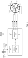
- FIG. 1 is an example general diagram of a motor control system.
- the motor system 100 (motor system or other suitable type system including one or more windings) includes controller 140 that controls operation of the motor 131.
- the motor 131 can be configured to include any number of windings.
- motor 131 includes multiple windings such as winding 131-1, winding 131-2, and winding 131-3.
- Motor 131 can be any type of motor.
- motor 131 can be PMSM (Permanent Magnet Synchronous Motor), BLDC (Brushless DC Motor), ACIM (AC Induction Motor) motor, etc.
- PMSM Permanent Magnet Synchronous Motor
- BLDC Battery DC Motor
- ACIM AC Induction Motor
- each of the windings of motor 131 is connected to a respective common node NC.
- the winding 131-1 is connected between the node N1 and the common node NC;
- the winding 131-2 is connected between the node N2 and the common node NC;
- the winding 131-3 is connected between the node N3 and the common node NC.
- the inverter 170 can be configured to include one or more switches.
- the switches in inverter 170 can be any suitable type such as MOSFETs (Metal Oxide Semiconductor Field Effect Transistors), IGBT (Insulated-Gate Bipolar Transistor), BJT (Bipolar Junction Transistors), etc.
- Controller 140 can be configured to further include signal generator 145 and inverter 170 (such as switch circuitry) to drive each of the windings 131-1, 131-2, and 131-3 associated with the motor 131.
- the controller 140 receives respective control input 104 from the user 108. Based on the control input 104, such as one or more signals indicating how to control operation of the motor 131, the controller 140 operates the signal generator 145 to produce control signals 105. Appropriate timing of control signals 105 controls operation of respective switches in the inverter 170 and variation in the magnitudes of current 121-1, 121-2, and 121-3, resulting a corresponding rotation of a shaft of the motor 131.
- the controller 140 may receive control input 104 indicating how to control operation of motor 131.
- the controller 140 controls a corresponding flow of current 121-1, 121-2, and 121-3 through respective windings 131-1, 131-2, and 131-3 of the motor 131.
- the controller 140 balances positive demagnetization and negative demagnetization of each of the multiple windings in a respective control cycle.
- FIG. 2 is an example diagram illustrating a motor control system.
- the inverter 170 includes switches(n-channel MOSFETs) such as switch Q1 (such as high side switch circuitry), switch Q2 (such as low side switch circuitry), switch Q3 (such as high side switch circuitry), switch Q4 (such as low side switch circuitry), switch Q5 (such as high side switch circuitry), and switch Q6 (such as low side switch circuitry).
- switches such as switch Q1 (such as high side switch circuitry), switch Q2 (such as low side switch circuitry), switch Q3 (such as high side switch circuitry), switch Q4 (such as low side switch circuitry), switch Q5 (such as high side switch circuitry), and switch Q6 (such as low side switch circuitry).
- Each of the pairs of switches may control delivery of current to a respective winding of the motor 131.
- the combination of switches Q1 and Q2 controls the voltage VN1 supplied to node N1 and thus delivery of current 121-1 through the winding 131-1.
- the combination of switches Q3 and Q4 controls the voltage VN2 supplied to node N2 and thus delivery of current 121-2 through the winding 131-2.
- the combination of switches Q5 and Q6 controls the voltage VN3 supplied to node N3 and thus delivery of current 121-3 through the winding 131-3.
- the inverter 170 and corresponding circuitry can be configured in any suitable manner.
- a combination of switch Q1 and switch Q2 can be configured to form a first series path between voltage source Vbus (supply voltage such as 24 VDC or other suitable value) and ground reference voltage (reference voltage).
- the drain node D of switch Q1 is coupled to the voltage Vbus.
- the source node of switch Q1 is connected to the drain node of switch Q2.
- the source node of switch Q2 is connected to a ground reference voltage.
- a combination of switch Q3 and switch Q4 form a second series path between voltage source Vbus (supply voltage such as 24 VDC or other suitable value) and ground.
- the drain node D of switch Q3 is coupled to the voltage Vbus.
- the source node of switch Q3 is connected to the drain node of switch Q4.
- the source node of switch Q4 is connected to a ground reference voltage.
- a combination of switch Q5 and switch Q6 form a third series path between voltage source Vbus (supply voltage such as 24 VDC or other suitable value) and ground.
- the drain node D of switch Q5 is coupled to the voltage Vbus.
- the source node of switch Q5 is connected to the drain node of switch Q6.
- the source node of switch Q6 is connected to a ground reference voltage.
- motor 130 includes three windings such as motor winding 131-1, motor winding 131-2, and motor winding 131-3.
- the sum of current 121-1, 121-2, and 121-3 through all windings 131-1, 131-2, and 131-3 is zero.
- the current in the third winding can be determined from the first two known magnitudes of current.
- nodes of all three windings 131-1, 131-2, and 131-3 are connected together at a common node NC of the motor 131.
- the pulse width modulation generator 145 produces control signals such as Qhu, Qlu, Qhv, Qlv, Qhw, Qlw) applied to respective switches Q1-Q6 to control control an amount of current through the windings.
- the signal generator 145 produces control signals Qhu, Qlu, Qhv, Qlv, Qhw, and Qlw.
- the signal generator 145 of controller 140 drives the gate node G of the switch Q1 with control signal Qhu; the signal generator 145 of controller 140 drives the gate node G of the switch Q2 with control signal Qlu; the signal generator 145 of controller 140 drives the gate node G of the switch Q3 with control signal Qhv; the signal generator 145 of controller 140 drives the gate node G of the switch Q4 with control signal Qlv; the signal generator 145 of controller 140 drives the gate node G of the switch Q5 with control signal Qhw; the signal generator 145 of controller 140 drives the gate node G of the switch Q6 with control signal Qlw.
- pulse width modulation controls signals (such as Qhu, Qlu, Qhv, Qlv, Qhw, Qlw) driving respective gate nodes of the switches of inverter 170 are shown in FIGS. 3 and 4 .
- FIG. 3 is an example diagram illustrating different conventional pulse width modulation driver patterns.
- Each of the pulse width modulation control patterns in FIG. 3 includes six sectors (such as sector #0, sector #1, sector #2, sector #3, sector #4, and sector #5) per control cycle of controlling one revolution of the shaft associated with the motor 131. Each sector corresponds to 60 degrees of rotation.
- the controller 140 repeats the respective PWM pattern for each of multiple cycles to control operation of the motor 131.
- the PWM type 0 pattern (also known as pattern 0) indicates settings of respective signals applied to the respective switches of inverter 170. Note that a logic high of a respective signal indicates to activate a corresponding switch (to an ON state, short, or low resistive path) of the inverter 170; a logic low of a respective drive signal indicates to deactivate a corresponding switch (to an OFF state, open circuit path, or high resistive path) of the inverter 170.
- the controller 140 i) toggles switches Q1 and Q2 between ON and OFF states; ii) deactivates both of switches Q3 and Q4, and iii) deactivates switch Q5 and activates the switch Q6.
- the controller 140 i) toggles switches Q3 and Q4 between ON and OFF states; ii) deactivates both of switches Q1 and Q2, and iii) deactivates switch Q5 and activates the switch Q6.
- the controller 140 i) toggles switches Q3 and Q4 between ON and OFF states; ii) deactivates both switches Q5 and Q6, and iii) deactivates switch Q1 and activates the switch Q2.
- the controller 140 i) toggles switches Q5 and Q6 between ON and OFF states; ii) deactivates both switches Q3 and Q4, and iii) deactivates switch Q1 and activates the switch Q2.
- the controller 140 i) toggles switches Q5 and Q6 between ON and OFF states; ii) deactivates both switches Q1 and Q2, and iii) deactivates switch Q3 and activates the switch Q4.
- the controller 140 i) toggles switches Q1 and Q2 between ON and OFF states; ii) deactivates both switches Q5 and Q6, and iii) deactivates switch Q3 and activates the switch Q4.
- the controller 140 For sectors of PWM type 0 in which the controller 140 switches the respective high side switch circuitry and low side switch circuitry ON and OFF, the controller 140 sets the duty cycle of switching depending on how much current is needed to drive the respective windings of motor 131.
- PWM pattern 1 operates in a similar manner as PWM type 0 except that the low side switches are not switched between on and off states.
- the controller 140 i) toggles switches Q5 and Q6 between ON and OFF states; ii) deactivates both of switches Q3 and Q4, and iii) activates switch Q1 and deactivates switch Q2.
- the controller 140 i) toggles switches Q5 and Q6 between ON and OFF states; ii) deactivates both of switches Q1 and Q2, and iii) activates switch Q3 and deactivates switch Q4.
- the controller 140 i) toggles switches Q1 and Q2 between ON and OFF states; ii) deactivates both of switches Q5 and Q6, and iii) activates switch Q3 and deactivates switch Q4.
- the controller 140 i) toggles switches Q1 and Q2 between ON and OFF states; ii) deactivates both of switches Q3 and Q4, and iii) activates switch Q5 and deactivates switch Q6.
- the controller 140 i) toggles switches Q3 and Q4 between ON and OFF states; ii) deactivates both of switches Q1 and Q2, and iii) activates switch Q5 and deactivates switch Q6.
- the controller 140 i) toggles switches Q3 and Q4 between ON and OFF states; ii) deactivates both of switches Q5 and Q6, and iii) activates switch Q1 and deactivates switch Q2.
- PWM type 3 operates in a similar manner as PWM type 2 except that the low side switches are not switched between on and off states.
- FIG. 4 is an example diagram illustrating a comparison of conventional pulse width modulation and novel driver patterns.
- Each of the pulse width modulation control patterns in FIG. 4 includes six sectors (such as sector #0, sector #1, sector #2, sector #3, sector #4, and sector #5) per control cycle of controlling one revolution of the shaft associated with the motor 131. Each sector corresponds to 60 degrees of rotation.
- the controller 140 repeats the respective PWM pattern for each of multiple cycles to control operation of the motor 131.
- the PWM type 4 pattern indicates signals applied to the respective switches of inverter 170.
- a logic high of a respective signal indicates to activate a corresponding switch (to an ON state, short, or low resistive path) of the inverter 170;
- a logic low of a respective drive signal indicates to deactivate a corresponding switch (to an OFF state, open circuit path, or high resistive path) of the inverter 170.
- the controller 140 i) toggles switches Q5 and Q6 between ON and OFF states; ii) deactivates both of switches Q3 and Q4, and iii) activates switch Q1 and deactivates the switch Q2.
- the controller 140 i) toggles switches Q3 and Q4 between ON and OFF states; ii) deactivates both of switches Q1 and Q2, and iii) deactivates switch Q5 and activates the switch Q6.
- the controller 140 i) toggles switches Q1 and Q2 between ON and OFF states; ii) deactivates both of switches Q5 and Q6, and iii) activates switch Q3 and deactivates the switch Q4.
- the controller 140 i) toggles switches Q5 and Q6 between ON and OFF states; ii) deactivates both of switches Q3 and Q4, and iii) deactivates switch Q1 and activates the switch Q2.
- the controller 140 i) toggles switches Q3 and Q4 between ON and OFF states; ii) deactivates both of switches Q1 and Q2, and iii) activates switch Q5 and deactivates the switch Q6.
- the controller 140 i) toggles switches Q1 and Q2 between ON and OFF states; ii) deactivates both of switches Q5 and Q6, and iii) deactivates switch Q3 and activates the switch Q4.
- the controller 140 For sectors of PWM type 4 in which the controller 140 switches the respective high side switch circuitry and low side switch circuitry ON and OFF, the controller 140 sets the duty cycle of switching switches depending on how much current is needed to drive the respective windings of motor 131.
- PWM type 5 operates in a similar manner as PWM type 4 except that the low side switches are not switched between on and off states.
- the controller 140 i) toggles switches Q1 and Q2 between ON and OFF states; ii) deactivates both of switches Q3 and Q4, and iii) deactivates switch Q5 and activates switch Q6.
- the controller 140 i) toggles switches Q5 and Q6 between ON and OFF states; ii) deactivates both of switches Q1 and Q2, and iii) activates switch Q3 and deactivates switch Q4.
- the controller 140 i) toggles switches Q3 and Q4 between ON and OFF states; ii) deactivates both of switches Q5 and Q6, and iii) deactivates switch Q1 and activates switch Q2.
- the controller 140 i) toggles switches Q1 and Q2 between ON and OFF states; ii) deactivates both of switches Q3 and Q4, and iii) activates switch Q5 and deactivates switch Q6.
- the controller 140 i) toggles switches Q5 and Q6 between ON and OFF states; ii) deactivates both of switches Q1 and Q2, and iii) deactivates switch Q3 and activates switch Q4.
- the controller 140 i) toggles switches Q3 and Q4 between ON and OFF states; ii) deactivates both of switches Q5 and Q6, and iii) activates switch Q1 and deactivates switch Q2.
- PWM type 7 operates in a similar manner as PWM type 6 except that the low side switches are not switched between on and off states as shown.
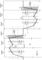
- FIG. 5 is an example diagram illustrating balanced positive demagnetization and negative demagnetization in a winding during a respective control cycle.
- the controller 140 balances positive demagnetization and negative demagnetization in a similar manner as shown in FIG. 5 for winding 131-1.
- graph 500 depicts the current 121-1 through winding 131-1 of motor 131 during a switching cycle of implementing the control signals associated with PWM pattern type 6.
- the switching cycle includes operation in multiple sectors (including sector #0, second #1, second #2, sector #3, sector #4, and sector #5).
- the controller 140 applies pattern 6 of pulse width modulation signals to control the winding 131-1.
- the PWM signals as discussed herein and applied to the switches in the inverter 170 include dead-time inserted between each PWM transition to prevent shoot-through current (that is, as is known in the art, dead time prevents shorting of the voltage Vbus to the ground reference voltage).
- high side switch circuitry and low side switch circuitry of a respective phase are not ON at the same time.
- the complementary switching of a respective high side switch and low side switch during each of the sectors of pattern 6 and 7 in a respective control cycle results in a sawtooth pattern as can be seen in current 121-1 through winding 131-1 as shown in graph 500.
- the current 121-1 through the winding 131-1 is substantially 0 amperes.
- Application of the pulse width modulation signals associated with sector #5 of PWM type 6 (see FIG. 4 for signals) between time T51 and T52 cause the magnitude of the current 121-1 to increase in a positive direction between time T51 at time T52.
- Positive demagnetization of the winding 131-1 includes starting at a positive current 121-1 through the winding 131-1 at time T53-1 and reducing the magnitude of the current 121-1 through (and corresponding energy and magnetic flux stored in) the winding 131-1 from a peak at time T53-1 to substantially zero Amperes (and zero magnetic flux) at around T53-2.
- the current 131-1 and magnetic flux in winding 131-1 is substantially 0 amperes between time T53-2 and time T54.
- the current 121-1 through the winding 131-1 is substantially 0 amperes.
- Application of the pulse width modulation signals associated with sector #2 of PWM type 6 (see FIG. 4 ) between time T54 and T55 causes the magnitude of the current 121-1 to increase (in a negative direction) between time T54 at time T55.
- negative demagnetization of the winding 131-1 includes starting at a peak negative current 121-1 through the winding 131-1 at or around time T56-1 and reducing the magnitude of the current 121-1 through (and corresponding energy stored in) the winding 131-1 from the peak current at time T56-1 to substantially zero Amperes at around T56-2.
- implementations herein include the controller 140 receiving control input 104 indicating how to control operation of the motor 131.
- the controller 140 uses the control input 104 as a basis in which to determine how to control the respective duty cycle of pulse width modulation signals driving the switches in the inverter 170.
- the controller 140 controls a corresponding flow of current 121-1, 121-2, and 121-3, through each of multiple windings 131-1, 131-2, and 131-3 of the motor 131 using pulse width modulation pattern 6 or 7. While controlling the corresponding flow of current through each of multiple windings, the controller 140 balances positive demagnetization and negative demagnetization of each of the multiple windings in each respective control cycle of multiple control cycles.
- the controller 140 applies the novel PWM control signals (such as PWM pattern type 6 control signals or PWM pattern type 7 control signals) to equalize the time duration TD1 of the positive demagnetization and the time duration TD2 of the negative demagnetization for each of the windings in motor 131 over a respective control cycle.
- novel PWM control signals such as PWM pattern type 6 control signals or PWM pattern type 7 control signals
- time duration TD1 is not exactly equal to but is substantially equal to the time duration TD2 due to variations in circuit parameters but within a threshold value of each other such as X%, where X is any integer value between 1 and 20.
- the controller 140 may control the TD2 to fall in a range between (1 + X%) x TD1 and (1 - X%) x TD1.
- the controller 140 can be configured to control a duration TD1 of the positive demagnetization (decreasing a magnitude of positive magnetic flux in the winding 131-1 to zero) and a duration TD2 of the negative demagnetization (decreasing a magnitude of negative magnetic flux in the winding 131-1 to zero) of each of the multiple windings in the respective control cycle to be within a threshold value of each other.
- the controller can be configured to control a first rate such as RATE1 (volts per second) of the positive demagnetization between time T53-1 and time T53-2 and a second rate such as RATE2 (volts per second) of the negative demagnetization between time T56-1 and T56-2 of each of the multiple windings in the respective control cycle to be within a threshold value such as X% (such as between 1% and 20%) or other suitable value of each other.
- RATE2 falls in a range between (1 + X%) x RATE1 and (1 - X%) x RATE1, or vice versa.
- implementation of the pulse width modulation controls signal patterns 6 or pattern 7 advantageously results in substantially equalizing a time duration TD1 of the positive demagnetization to a duration TD2 of the negative demagnetization of each of the multiple windings in the respective control cycle.
- implementation of the pulse width modulation patterns 6 and 7 via the controller results in controlling current through each of the multiple windings 131-1, 131-2, and 131-3 of the motor 131 such that an average magnitude of the current 121-1, 121-2, and 121-3 through each of the multiple windings is substantially equal during the respective control cycle.
- pulse width modulation and substantial equalization of the positive demagnetization time and negative demagnetization time provides beneficial operation such as one or more of the following: i) evenly distributed power dissipation amongst high side switch and low side switch on each motor phase, ii) during commutation (switch from one PWM sector to another), demagnetization time of non-excited phases becomes shorter, which helps reduce power loss, iii) during commutation, current rising time of new excited phase becomes shorter, which helps increase BLDC motor control efficiency.
- FIG. 6 is an example model illustrating components of a respective motor driver and corresponding windings in a motor.
- the winding 131-1 is modeled to include an inductance L1, resistance R1, and voltage source Eu for back EMF voltage;
- the winding 131-2 is modeled to include an inductance L2, resistance R2, and voltage source Ev for back EMF voltage
- the winding 131-3 is modeled to include an inductance L3, resistance R3, and voltage source Ew for back EMF voltage.
- FIG. 7A is an example diagram illustrating operation of the motor in sector #1 during positive demagnetization.
- the graph 710 of FIG. 7A illustrates current through the winding 131-1 (U-winding) and presence of a back electro-magnetic force (emf) voltage.
- emf electro-magnetic force
- the rotor back EMF voltage angle is at 60 degrees.
- FIG. 7B is an example diagram illustrating implementation of a conventional pulse width modulation drive pattern during sector #1. Implementation of the pulse width modulation patterns 0, 1, 4, and 5 result in slow demagnetization in sector #1.
- the inverter 170 output for sector #1 (for patterns 0, 1, 4, and 5) and respective voltages of nodes is as follows:
- the voltage Vnc Vbus ⁇ D/3, where the voltage Vnc is a magnitude of the voltage at the common node NC of the motor 131.
- Vbus, Eu, and Im are positive values in this case, the voltage Vlu across the first node N1 and node NC of the winding 131-1 is negative, resulting in a decrease of the magnitude of the current 121-1 to zero.
- FIG. 7C is an example diagram illustrating implementation of a pulse width modulation drive pattern during sector #1.
- the inverter 170 output for sector #1 (for patterns 2, 3, 6, and 7) is as follows:
- the voltage Vnc Vbus ⁇ (2/3 -D/3), where the voltage Vnc is a magnitude of the voltage at the common node NC of the motor 131.
- the voltage Vlu across the winding 131-1 is also negative in this case, and the magnitude of the current 121-1 through the winding 131-1 is greater in magnitude for sector #1 of patterns 2, 3, 6, and 7 than as in patterns 0, 1, 4, and 5.
- D 60% or 0.6
- the term [- Vbus ⁇ (2/3 -D/3)] is a greater negative value (or magnitude) than [- Vbus ⁇ D/3].
- the controller 140 deactivates switches Q1 and Q2 coupled to a node N1 of the first winding 131-1 to decrease a magnitude of magnetic flux in the first winding 131-1 to zero between time T53-1 and T53-2; ii) applies a bus voltage Vbus to a node of the second winding 131-2 via activation of switch Q3; and iii) via switches Q5 and Q6, switches between applying the bus voltage Vbus to a node N3 of the third winding 131-3 and applying a ground reference voltage associated with the bus voltage to the node N3 of the third winding 131 in accordance with a first duty cycle D.
- FIG. 8A is an example diagram illustrating operation of the motor in sector #1 during positive demagnetization.
- the graph 810 in FIG. 8A illustrates negative current through the winding 131-1 (U-winding) and presence of a back electro-magnetic force (emf) voltage.
- emf electro-magnetic force
- the winding 131-1 (a.k.a., U-winding) phase current starts with negative Im (a.k.a., current 121-1) and then increases to 0 (e.g., the V winding 131-2 starts with 0 current and then decreases to -Im; the W phase current stays at positive current Im).
- the rotor back EMF voltage angle of the motor 131 is at 240 degrees.
- FIG. 8B is an example diagram illustrating implementation of a conventional pulse width modulation drive pattern during sector #4.
- the inverter 170 output for sector #4 (for patterns 2, 3, 4, and 5) is as follows:
- the voltage Vnc Vbus ⁇ (1 - D/3), where the voltage Vnc is a magnitude of the voltage at the common node NC of the motor 131.
- Vbus is a DC voltage
- R1 is a resistance of the winding 131-1
- FIG. 8C is an example diagram illustrating implementation of a pulse width modulation drive pattern during sector #1.
- the inverter 170 output for sector #1 (for patterns 0, 1, 6, and 7) is as follows:
- the voltage Vnc Vbus ⁇ (1/3 + D/3), where the voltage Vnc is a magnitude of the voltage at the common node NC of the motor 131.
- the controller 140 deactivates the switches Q1 and Q2 coupled to the node N1 of the first winding 131-1 to decrease the magnitude of magnetic flux in the first winding 131-1 to zero; ii) applies the ground reference voltage to the node N2 of the second winding 131-2 via activation of the switch Q4; and iii) switches between applying the bus voltage Vbus to the node N3 of the third winding 131-3 and applying the ground reference voltage to the second node N3 of the third winding 131-3 in accordance with a second duty cycle (1-D).
- the voltage Vlu across the winding 131-1 is also negative, and the magnitude of the current 121-1 through the winding 131-1 is greater in magnitude for sector #1 of patterns 0, 1, 6, and 7 than as in patterns 2, 3, 4, and 5.
- Vbus ⁇ (2/3 -D/3) is a greater negative value than Vbus ⁇ D/3.
- each of the multiple windings of the motor 131 are electrically connected to a common node NC.
- the controller 140 controls a magnitude of a voltage across a first winding 131-1 of the multiple windings to a first value (such as -Vbus ⁇ D/3) during positive demagnetization of the first winding 131-1 in the respective control cycle; the controller 131-1 controls a magnitude of the voltage across the first winding to a second value (such as Vbus ⁇ D/3) during negative demagnetization of the first winding 131-1.
- a magnitude of the second value may be substantially equal to a magnitude of the first value such that time duration TD1 is substantially equal to the time duration TD2.
- FIG. 9 is an example diagram illustrating high side switch circuitry and low side switch circuitry losses at different torque settings of the motor during application of PWM type 6.
- Graph 910 illustrates different power losses associated with high side switch circuitry (such as switches Q1, Q3, and Q5) at different torque loads of the motor 131.
- the controller 140 implements the pulse width modulation pattern associated with PWM pattern type 6 or 7 to control operation of the motor 131.
- X represents power conduction losses of operating the respective switches Q1, Q3, and Q5;
- Y represents power switching losses of operating the respective switches Q1, Q3, and Q5;
- Z represents diode losses (power loss from inherent diodes associated with) switches Q1, Q3, and Q5.
- Graph 920 illustrates different power losses associated with low side switch circuitry (such as switches Q2, Q4, and Q6) at different torque loads of the motor 131.
- the controller 140 implements the pulse width modulation pattern associated with PWM type 6 to control operation of the motor 131.
- X represents power conduction losses of operating the respective switches Q2, Q4, and Q6;
- Y represents power switching losses of operating the respective switches Q2, Q4, and Q6;
- Z represents diode losses (power loss from inherent diodes associated with) switches Q2, Q4, and Q6.
- implementation of the PWM type 6 or PWM type 7 control patterns results in balancing (or equalizing) of positive demagnetization and negative demagnetization of one or more windings of motor 131 in each control cycle of operating the motor 131.
- implementation of these control patterns (PWM type 6 or PWM type 7) and corresponding balancing results in substantially equal power losses with respect to high side switch circuitry (switches Q1, Q3, and Q5) and low side switch circuitry (switches Q2, Q4, Q6).
- the balance of power losses as shown in FIG. 10 reduces stress on the switches because it is balanced as opposed to an imbalance of heat being dissipated mostly by high side switch circuitry or low side switch circuitry.
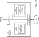
- FIG. 10 is an example block diagram of a computer device for implementing any of the operations as discussed herein.
- computer system 1000 (such as implemented by any of one or more resources such as controller 140, signal generator 145, etc.) of the present example includes an interconnect 1011 that couples computer readable storage media 1012 such as a non-transitory type of media (or hardware storage media) in which digital information can be stored and retrieved, a processor 1013 (e.g., computer processor hardware such as one or more processor devices), I/O interface 1014, and a communications interface 1017.
- computer readable storage media 1012 such as a non-transitory type of media (or hardware storage media) in which digital information can be stored and retrieved
- processor 1013 e.g., computer processor hardware such as one or more processor devices
- I/O interface 1014 e.g., I/O interface
- I/O interface 1014 provides connectivity to any suitable circuitry or component such as user interface 115, winding 131, amplifier 145, etc.
- Computer readable storage medium 1012 can be any hardware storage resource or device such as memory, optical storage, hard drive, floppy disk, etc.
- the computer readable storage medium 1012 can be configured to store instructions and/or data used by the controller application 140-1 to perform any of the operations as described herein.
- communications interface 1017 enables the computer system 1000 and processor 1013 to communicate over a resource such as network 190 to retrieve information from remote sources and communicate with other computers.
- controller application 140-1 e.g., software, firmware, etc.
- Controller application 140-1 can be configured to include instructions to implement any of the operations as discussed herein.
- processor 1013 accesses computer readable storage media 1012 via the use of interconnect 1011 in order to launch, run, execute, interpret or otherwise perform the instructions in controller application 140-1 stored on computer readable storage medium 1012.
- controller application 140-1 produces processing functionality such as controller process 140-2 in processor 1013.
- controller process 140-2 associated with processor 1013 represents one or more aspects of executing controller application 140-1 within or upon the processor 1013 in the computer system 1000.
- computer system 1000 can be a micro-controller device, logic, hardware processor, hybrid analog/digital circuitry, etc., configured to control a power supply and perform any of the operations as described herein.
- FIG. 11 is an example diagram illustrating a method of controlling a power converter.
- the controller 140 receives control input 104.
- the controller 140 controls current through each of the multiple windings 131-1, 131-2, and 131-3 of motor 131.
- the controller 140 balances positive demagnetization and negative demagnetization of each of the multiple windings of the motor 131 in a respective control cycle of controlling the current.
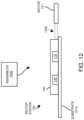
- FIG. 12 is an example diagram illustrating assembly of a control system (such as a circuit).
- assembler 1240 receives a substrate 1210 and corresponding components of system 100 such as one or more of controller 140, signal generator 145, inverter 170 (such as one or more sets of switches), etc.
- the assembler 1240 affixes (couples) components associated with the controller 140 and other components such as signal generator 145, inverter 170, etc., to the substrate 1210.
- the fabricator 1240 provides connectivity between one or more components such as controller 140, signal generator 145, inverter 170, etc.
- components such as the signal generator 145, inverter 170, etc.
- the substrate 1210 can be soldered to the substrate 1210, inserted into sockets disposed on the substrate 1210, etc.
- substrate 1210 is optional. Any of one or more circuit paths or connectivity as shown in the above drawings and as described herein can be disposed in cables, flexible substrates, or other suitable media.
- the motor 131 is disposed on its own assembly independent of substrate 1210; the substrate or housing of the motor 131 is directly or indirectly connected to the substrate 1210 via wires, cables, links, etc.
- the controller 140 or any portion of the motor system 100 can be disposed on a standalone smaller board plugged into a socket of the substrate 1210 as well.
- the assembler 1240 couples the system 100 and corresponding components to the motor 131 and corresponding windings.
- the circuit path 1222 conveys current 121-1, 121-2, 121-3, etc., from an input voltage source such as Vbus and ground reference voltage to the motor 131 as controlled by switches in inverter 170.
- this disclosure includes a system comprising: a substrate 1210 (such as a circuit board, standalone board, mother board, standalone board destined to be coupled to a mother board, host, etc.); a system 100 of corresponding components (such as associated with controller 140, signal generator 145, inverter 170, etc.) as described herein; and at least one winding (such as a motor, winding, etc.).
- a substrate 1210 such as a circuit board, standalone board, mother board, standalone board destined to be coupled to a mother board, host, etc.
- a system 100 of corresponding components such as associated with controller 140, signal generator 145, inverter 170, etc.
- at least one winding such as a motor, winding, etc.
- An algorithm as described herein, and generally, is considered to be a self-consistent sequence of operations or similar processing leading to a desired result.
- operations or processing involve physical manipulation of physical quantities.
- quantities may take the form of electrical or magnetic signals capable of being stored, transferred, combined, compared or otherwise manipulated. It has been convenient at times, principally for reasons of common usage, to refer to such signals as bits, data, values, elements, symbols, characters, terms, numbers, numerals or the like. It should be understood, however, that all of these and similar terms are to be associated with appropriate physical quantities and are merely convenient labels.
Landscapes
- Engineering & Computer Science (AREA)
- Power Engineering (AREA)
- Control Of Ac Motors In General (AREA)
Abstract
Description
- Implementation of conventional brushless DC motors (a.k.a., BLDC motors) are susceptible to imbalance of power losses. For example, implementation of a conventional BLDC pulse width modulation drive scheme results in unevenly distributed power dissipation between respective high side switch circuitry and low side switch circuitry controlling the flow of current through windings of the motor during winding demagnetization, which occurs twice per control cycle. For example, the implementation of conventional BLDC pulse width modulation drive schemes shows inconsistent rates of rising and falling during positive and negative demagnetization of respective motor windings. Slower demagnetization times results in higher power losses.
- Conventional motor applications include implementation of software to speed-up demagnetization of respective windings. However, ideal demagnetization times vary depending on one or more factors such as motor speed, DC bus voltage, and load conditions.
- An apparatus as defined in
claim 1, a system as defined in claim 12, a method as defined in claim 13 or 14 and a computer readable storage medium as defined in claim 15 are provided. The dependent claims define further embodiments. - In contrast to conventional techniques, this disclosure includes novel ways of improving positive demagnetization and negative demagnetization of windings in a motor.
- More specifically, an apparatus and/or system may include a controller. The controller may receive control input indicating how to control operation of a motor. In accordance with the control input, the controller may control a corresponding flow of current through at least one of multiple windings of the motor. While controlling the corresponding flow of current through each of the multiple windings, the controller may balance positive demagnetization (such as a mode of reducing the amount of positive magnetic flux in the at least one winding to zero) and negative demagnetization (such as a mode of reducing the amount of negative magnetic flux in the at least one winding to zero) of the at least one winding in a respective control cycle.
- Further, the controller may control a rate of the positive demagnetization and a rate of the negative demagnetization of the at least one winding in the respective control cycle to be substantially equal.
- Yet further, the controller may control a time duration of the positive demagnetization and a time duration of the negative demagnetization of the at least one winding in the respective control cycle to be substantially equal of each other. Thus, in such an instance, the controller may substantially equalize a duration of the positive demagnetization to a duration of the negative demagnetization of one or more of the multiple windings in the respective control cycle.
- The controller may be further operative to control a magnitude of a duration of the negative demagnetization of the at least one winding in the respective control cycle to be within a threshold value of 5% (or other suitable value such as 1%, 3%, 10%, etc.) of a magnitude of the duration of the positive demagnetization. For example, if the duration of the positive demagnetization of a first winding is 100 microseconds, and the threshold value is 5%, the controller may control the magnitude of the duration of the negative demagnetization of the winding in the respective cycle to be between 95 and 105 microseconds, or vice versa.
- Still further, the controller may control current through each of the multiple windings of the motor such that an average magnitude of the current through each of the multiple windings is substantially equal during the respective control cycle.
- Yet further, a node of each of the multiple windings of the motor may be electrically connected to a common node. The controller may control a magnitude of a voltage across a first winding of the multiple windings to a first value during positive demagnetization of the first winding in the respective control cycle; the controller may control a magnitude of the voltage across the first winding to a second value during negative demagnetization of the first winding. A magnitude of the second value substantially equal to a magnitude of the first value.
- As previously discussed, the controller may implement balancing of the positive demagnetization and the negative demagnetization of each of the multiple windings in the respective control cycle. The balancing of the positive demagnetization and the negative demagnetization may equalize power losses (and corresponding heat dissipation) associated with high side switch circuitry and low side switch circuitry providing the current through each of the multiple windings of the motor in the respective control cycle.
- Additionally, note that the apparatus as discussed herein may include multiple current drivers such as associated with an inverter. The multiple current drivers (each including high side switch circuitry and low side switch circuitry) may be controlled by the controller and supply the current through each of the multiple windings of the motor.
- Yet further, the multiple windings of the motor may include a first winding, a second winding, and a third winding. A first node of the first winding, a first node of the second winding, and a first node of the third winding may be electrically connected to each other at a common electrical node of the motor.
- The at least one winding as discussed herein may be a first winding. During the positive demagnetization, in order to decrease a magnitude of magnetic flux in the first winding, the controller may: i) deactivate switches coupled to a node of the first winding to zero; ii) apply a bus voltage to a node of the second winding; and iii) switch between applying the bus voltage to a node of the third winding and applying a reference voltage associated with the bus voltage to the node of the third winding in accordance with a first duty cycle (D).
- During the negative demagnetization, in order to decrease the magnitude of magnetic flux in the first winding, the controller may: i) deactivate the switches coupled to the node of the first winding to zero; ii) apply the reference voltage to the node of the second winding; and iii) switch between applying the bus voltage to the node of the third winding and applying the reference voltage to the node of the third winding in accordance with a second duty cycle (1-D).
- Yet further, deactivation of the switches coupled to the first winding during the positive demagnetization may cause an inherent diode of a first switch of the switches to provide electrical connectivity of the node of the first winding to the reference voltage during the positive demagnetization of the first winding; deactivation of the switches coupled to the first winding during the negative demagnetization may cause an inherent diode of a second switch of the switches to provide electrical connectivity of the node of the first winding to the bus voltage during the negative demagnetization of the first winding. The first switch and the second switch may be connected in series between a first voltage source supplying the bus voltage and a second voltage source supplying the reference voltage (such as a ground reference voltage).
- Implementation of pulse width modulation as discussed herein may provide beneficial operation such as one or more of the following: i) evenly distributed power dissipation amongst high side switch circuitry and low side switch circuitry on each motor phase, ii) during commutation (switch from one PWM sector to another), demagnetization time of non-excited phases becomes shorter, which helps reduce the loss, iii) during commutation, current rising time of new excited phase becomes shorter, which helps increase BLDC motor control efficiency.
- These and other more specific concepts are disclosed in more detail below.
- Note that although techniques as discussed herein are applicable to controlling current through multiple windings, the concepts disclosed herein may be advantageously applied in any suitable application.
- Note further that any of the resources as discussed herein may can include one or more computerized devices, mobile communication devices, servers, base stations, wireless communication equipment, communication management systems, workstations, user equipment, handheld or laptop computers, or the like to carry out and/or support any or all of the method operations disclosed herein. In other words, one or more computerized devices or processors can be programmed and/or configured to operate as explained herein to carry out the different techniques as described herein.
- Yet other implementations herein may include software programs to perform the steps and operations summarized above and disclosed in detail below. One such implementation comprises a computer program product including a non-transitory computer-readable storage medium (i.e., any computer readable hardware storage medium) on which software instructions are encoded for subsequent execution. The instructions, when executed in a computerized device (hardware) having a processor, program and/or cause the processor (hardware) to perform the operations disclosed herein. Such arrangements are typically provided as software, code, instructions, and/or other data (e.g., data structures) arranged or encoded on a non-transitory computer readable storage medium such as an optical medium (e.g., CD-ROM), floppy disk, hard disk, memory stick, memory device, etc., or other a medium such as firmware in one or more ROM, RAM, PROM, etc., or as an Application Specific Integrated Circuit (ASIC), etc. The software or firmware or other such configurations can be installed onto a computerized device to cause the computerized device to perform the techniques explained herein.
- Accordingly, this disclosure is directed to one or more of methods, systems, computer program products, etc., that support operations as discussed herein.
- A computer readable storage medium and/or system may have instructions stored thereon. The instructions, when executed by computer processor hardware, may cause the computer processor hardware (such as one or more co-located or disparately located processor devices) to: receive control input; in accordance with the control input, control current through each of multiple windings of a motor; and balance positive demagnetization and negative demagnetization of at least one of the multiple windings in a respective control cycle of controlling the current.
- The ordering of the steps above has been added for clarity sake. Note that any of the processing operations as discussed herein can be performed in any suitable order.
- Further techniques herein may include software programs and/or respective hardware to perform any of the methods including steps and/or operations summarized above and disclosed in detail below.
- It is to be understood that the system, method, apparatus, instructions on computer readable storage media, etc., as discussed herein also can be embodied strictly as a software program, firmware, as a hybrid of software, hardware and/or firmware, or as hardware alone such as within a processor (hardware or software), or within an operating system or a within a software application.
- As discussed herein, techniques herein are well suited for use in the field of controlling current through windings of motor to provide torque in respective movement of a motor shaft. However, it should be noted that this disclosure is not limited to use in such applications and that the techniques discussed herein are well suited for other applications as well.
- Additionally, note that although each of the different features, techniques, configurations, etc., herein may be discussed in different places of this disclosure, it is intended, where suitable, that each of the concepts can optionally be executed independently of each other or in combination with each other. Accordingly, the one or more present inventions as described herein can be implemented and viewed in many different ways.
- Also, note that this preliminary discussion herein (BRIEF DESCRIPTION) purposefully does not specify every implementation and/or incrementally novel aspect of the present disclosure or claimed invention(s). Instead, this brief description only presents general implementations and corresponding points of novelty over conventional techniques. For additional details and/or possible perspectives (permutations) of the invention(s), the reader is directed to the Detailed Description section (which is a summary of possible implementation and operations) and corresponding figures of the present disclosure as further discussed below.
-
-
FIG. 1 is an example general diagram of a motor and corresponding control system. -
FIG. 2 is an example diagram illustrating details of the motor control system. -
FIG. 3 is an example diagram illustrating different pulse width modulation driver patterns. -
FIG. 4 is an example diagram illustrating a comparison of conventional pulse width modulation patterns and novel driver patterns. -
FIG. 5 is an example diagram illustrating balanced positive demagnetization of a winding and negative demagnetization of the winding in a respective control cycle. -
FIG. 6 is an example model illustrating components of a respective motor driver and corresponding windings in a motor. -
FIG. 7A is an example diagram illustrating operation of the motor during positive demagnetization. -
FIG. 7B is an example diagram illustrating implementation of a conventional pulse width modulation drive pattern. -
FIG. 7C is an example diagram illustrating implementation of a pulse width modulation drive pattern. -
FIG. 8A is an example diagram illustrating operation of the motor during positive demagnetization. -
FIG. 8B is an example diagram illustrating implementation of a conventional pulse width modulation drive pattern. -
FIG. 8C is an example diagram illustrating implementation of a pulse width modulation drive pattern. -
FIG. 9 is an example diagram illustrating high side switch circuitry and low side switch circuitry losses at different torque settings of the motor. -
FIG. 10 is an example diagram illustrating computer processor hardware and related software instructions that execute methods as described herein. -
FIG. 11 is an example diagram illustrating a method as discussed herein. -
FIG. 12 is an example diagram illustrating assembly of a circuit as discussed herein. - The foregoing and other objects, features, and advantages of the invention will be apparent from the following more particular description of preferred implementations herein, as illustrated in the accompanying drawings in which like reference characters refer to the same parts throughout the different views. The drawings are not necessarily to scale, with emphasis instead being placed upon illustrating the implementations, operations, principles, concepts, etc.
- Now, more specifically,
FIG. 1 is an example general diagram of a motor control system. - As shown, the motor system 100 (motor system or other suitable type system including one or more windings) includes
controller 140 that controls operation of themotor 131. Themotor 131 can be configured to include any number of windings. In this non-limiting example,motor 131 includes multiple windings such as winding 131-1, winding 131-2, and winding 131-3. -
Motor 131 can be any type of motor. For example,motor 131 can be PMSM (Permanent Magnet Synchronous Motor), BLDC (Brushless DC Motor), ACIM (AC Induction Motor) motor, etc. - Further, one end of each of the windings of
motor 131 is connected to a respective common node NC. For example, the winding 131-1 is connected between the node N1 and the common node NC; the winding 131-2 is connected between the node N2 and the common node NC; the winding 131-3 is connected between the node N3 and the common node NC. - The
inverter 170 can be configured to include one or more switches. The switches ininverter 170 can be any suitable type such as MOSFETs (Metal Oxide Semiconductor Field Effect Transistors), IGBT (Insulated-Gate Bipolar Transistor), BJT (Bipolar Junction Transistors), etc. -
Controller 140 can be configured to further includesignal generator 145 and inverter 170 (such as switch circuitry) to drive each of the windings 131-1, 131-2, and 131-3 associated with themotor 131. For example, thecontroller 140 receivesrespective control input 104 from the user 108. Based on thecontrol input 104, such as one or more signals indicating how to control operation of themotor 131, thecontroller 140 operates thesignal generator 145 to produce control signals 105. Appropriate timing ofcontrol signals 105 controls operation of respective switches in theinverter 170 and variation in the magnitudes of current 121-1, 121-2, and 121-3, resulting a corresponding rotation of a shaft of themotor 131. - Thus, the
controller 140 may receivecontrol input 104 indicating how to control operation ofmotor 131. In accordance with thecontrol input 104, thecontroller 140 controls a corresponding flow of current 121-1, 121-2, and 121-3 through respective windings 131-1, 131-2, and 131-3 of themotor 131. According to one implementation as further discussed herein, via generation of control signals 105 (such as pulse width modulation signals), thecontroller 140 balances positive demagnetization and negative demagnetization of each of the multiple windings in a respective control cycle. -
FIG. 2 is an example diagram illustrating a motor control system. - In this example, the
inverter 170 includes switches(n-channel MOSFETs) such as switch Q1 (such as high side switch circuitry), switch Q2 (such as low side switch circuitry), switch Q3 (such as high side switch circuitry), switch Q4 (such as low side switch circuitry), switch Q5 (such as high side switch circuitry), and switch Q6 (such as low side switch circuitry). - Each of the pairs of switches may control delivery of current to a respective winding of the
motor 131. For example, the combination of switches Q1 and Q2 controls the voltage VN1 supplied to node N1 and thus delivery of current 121-1 through the winding 131-1. The combination of switches Q3 and Q4 controls the voltage VN2 supplied to node N2 and thus delivery of current 121-2 through the winding 131-2. The combination of switches Q5 and Q6 controls the voltage VN3 supplied to node N3 and thus delivery of current 121-3 through the winding 131-3. - As shown, the
inverter 170 and corresponding circuitry can be configured in any suitable manner. For example, a combination of switch Q1 and switch Q2 can be configured to form a first series path between voltage source Vbus (supply voltage such as 24 VDC or other suitable value) and ground reference voltage (reference voltage). The drain node D of switch Q1 is coupled to the voltage Vbus. The source node of switch Q1 is connected to the drain node of switch Q2. The source node of switch Q2 is connected to a ground reference voltage. - As further shown, a combination of switch Q3 and switch Q4 form a second series path between voltage source Vbus (supply voltage such as 24 VDC or other suitable value) and ground. The drain node D of switch Q3 is coupled to the voltage Vbus. The source node of switch Q3 is connected to the drain node of switch Q4. The source node of switch Q4 is connected to a ground reference voltage.
- Yet as further shown, a combination of switch Q5 and switch Q6 form a third series path between voltage source Vbus (supply voltage such as 24 VDC or other suitable value) and ground. The drain node D of switch Q5 is coupled to the voltage Vbus. The source node of switch Q5 is connected to the drain node of switch Q6. The source node of switch Q6 is connected to a ground reference voltage.
- As previously discussed, motor 130 includes three windings such as motor winding 131-1, motor winding 131-2, and motor winding 131-3. The sum of current 121-1, 121-2, and 121-3 through all windings 131-1, 131-2, and 131-3 is zero. Hence, if a magnitude of currents through two windings is known, the current in the third winding can be determined from the first two known magnitudes of current.
- As previously discussed, nodes of all three windings 131-1, 131-2, and 131-3 are connected together at a common node NC of the
motor 131. - Yet further, via generation of the control signals 105, the pulse
width modulation generator 145 produces control signals such as Qhu, Qlu, Qhv, Qlv, Qhw, Qlw) applied to respective switches Q1-Q6 to control control an amount of current through the windings. For example, based oncontrol signals 105, thesignal generator 145 produces control signals Qhu, Qlu, Qhv, Qlv, Qhw, and Qlw. - The
signal generator 145 ofcontroller 140 drives the gate node G of the switch Q1 with control signal Qhu; thesignal generator 145 ofcontroller 140 drives the gate node G of the switch Q2 with control signal Qlu; thesignal generator 145 ofcontroller 140 drives the gate node G of the switch Q3 with control signal Qhv; thesignal generator 145 ofcontroller 140 drives the gate node G of the switch Q4 with control signal Qlv; thesignal generator 145 ofcontroller 140 drives the gate node G of the switch Q5 with control signal Qhw; thesignal generator 145 ofcontroller 140 drives the gate node G of the switch Q6 with control signal Qlw. - Examples of pulse width modulation controls signals (such as Qhu, Qlu, Qhv, Qlv, Qhw, Qlw) driving respective gate nodes of the switches of
inverter 170 are shown inFIGS. 3 and4 . -
FIG. 3 is an example diagram illustrating different conventional pulse width modulation driver patterns. - Each of the pulse width modulation control patterns in
FIG. 3 includes six sectors (such assector # 0,sector # 1,sector # 2,sector # 3,sector # 4, and sector #5) per control cycle of controlling one revolution of the shaft associated with themotor 131. Each sector corresponds to 60 degrees of rotation. Thecontroller 140 repeats the respective PWM pattern for each of multiple cycles to control operation of themotor 131. - As further shown, the
PWM type 0 pattern (also known as pattern 0) indicates settings of respective signals applied to the respective switches ofinverter 170. Note that a logic high of a respective signal indicates to activate a corresponding switch (to an ON state, short, or low resistive path) of theinverter 170; a logic low of a respective drive signal indicates to deactivate a corresponding switch (to an OFF state, open circuit path, or high resistive path) of theinverter 170. - Thus, as shown, during
sector # 0 ofPWM pattern 0, the controller 140: i) toggles switches Q1 and Q2 between ON and OFF states; ii) deactivates both of switches Q3 and Q4, and iii) deactivates switch Q5 and activates the switch Q6. - During
sector # 1 ofPWM pattern 0, the controller 140: i) toggles switches Q3 and Q4 between ON and OFF states; ii) deactivates both of switches Q1 and Q2, and iii) deactivates switch Q5 and activates the switch Q6. - During
sector # 2 ofPWM type 0, the controller 140: i) toggles switches Q3 and Q4 between ON and OFF states; ii) deactivates both switches Q5 and Q6, and iii) deactivates switch Q1 and activates the switch Q2. - During
sector # 3 ofPWM type 0, the controller 140: i) toggles switches Q5 and Q6 between ON and OFF states; ii) deactivates both switches Q3 and Q4, and iii) deactivates switch Q1 and activates the switch Q2. - During
sector # 4 ofPWM type 0, the controller 140: i) toggles switches Q5 and Q6 between ON and OFF states; ii) deactivates both switches Q1 and Q2, and iii) deactivates switch Q3 and activates the switch Q4. - During
sector # 5 ofPWM type 0, the controller 140: i) toggles switches Q1 and Q2 between ON and OFF states; ii) deactivates both switches Q5 and Q6, and iii) deactivates switch Q3 and activates the switch Q4. - For sectors of
PWM type 0 in which thecontroller 140 switches the respective high side switch circuitry and low side switch circuitry ON and OFF, thecontroller 140 sets the duty cycle of switching depending on how much current is needed to drive the respective windings ofmotor 131. -
PWM pattern 1 operates in a similar manner asPWM type 0 except that the low side switches are not switched between on and off states. - During
sector # 0 ofPWM type 2, the controller 140: i) toggles switches Q5 and Q6 between ON and OFF states; ii) deactivates both of switches Q3 and Q4, and iii) activates switch Q1 and deactivates switch Q2. - During
sector # 1 ofPWM type 2, the controller 140: i) toggles switches Q5 and Q6 between ON and OFF states; ii) deactivates both of switches Q1 and Q2, and iii) activates switch Q3 and deactivates switch Q4. - During
sector # 2 ofPWM type 2, the controller 140: i) toggles switches Q1 and Q2 between ON and OFF states; ii) deactivates both of switches Q5 and Q6, and iii) activates switch Q3 and deactivates switch Q4. - During
sector # 3 ofPWM type 2, the controller 140: i) toggles switches Q1 and Q2 between ON and OFF states; ii) deactivates both of switches Q3 and Q4, and iii) activates switch Q5 and deactivates switch Q6. - During
sector # 4 ofPWM type 2, the controller 140: i) toggles switches Q3 and Q4 between ON and OFF states; ii) deactivates both of switches Q1 and Q2, and iii) activates switch Q5 and deactivates switch Q6. - During
sector # 5 ofPWM type 2, the controller 140: i) toggles switches Q3 and Q4 between ON and OFF states; ii) deactivates both of switches Q5 and Q6, and iii) activates switch Q1 and deactivates switch Q2. -
PWM type 3 operates in a similar manner asPWM type 2 except that the low side switches are not switched between on and off states. -
FIG. 4 is an example diagram illustrating a comparison of conventional pulse width modulation and novel driver patterns. - Each of the pulse width modulation control patterns in
FIG. 4 includes six sectors (such assector # 0,sector # 1,sector # 2,sector # 3,sector # 4, and sector #5) per control cycle of controlling one revolution of the shaft associated with themotor 131. Each sector corresponds to 60 degrees of rotation. Thecontroller 140 repeats the respective PWM pattern for each of multiple cycles to control operation of themotor 131. - As further shown, the
PWM type 4 pattern indicates signals applied to the respective switches ofinverter 170. A logic high of a respective signal indicates to activate a corresponding switch (to an ON state, short, or low resistive path) of theinverter 170; a logic low of a respective drive signal indicates to deactivate a corresponding switch (to an OFF state, open circuit path, or high resistive path) of theinverter 170. - Thus, as shown, during
sector # 0 ofPWM pattern 4, the controller 140: i) toggles switches Q5 and Q6 between ON and OFF states; ii) deactivates both of switches Q3 and Q4, and iii) activates switch Q1 and deactivates the switch Q2. - During
sector # 1 ofPWM type 4, the controller 140: i) toggles switches Q3 and Q4 between ON and OFF states; ii) deactivates both of switches Q1 and Q2, and iii) deactivates switch Q5 and activates the switch Q6. - During
sector # 2 ofPWM type 4, the controller 140: i) toggles switches Q1 and Q2 between ON and OFF states; ii) deactivates both of switches Q5 and Q6, and iii) activates switch Q3 and deactivates the switch Q4. - During
sector # 3 ofPWM type 4, the controller 140: i) toggles switches Q5 and Q6 between ON and OFF states; ii) deactivates both of switches Q3 and Q4, and iii) deactivates switch Q1 and activates the switch Q2. - During
sector # 4 ofPWM type 4, the controller 140: i) toggles switches Q3 and Q4 between ON and OFF states; ii) deactivates both of switches Q1 and Q2, and iii) activates switch Q5 and deactivates the switch Q6. - During
sector # 5 ofPWM type 4, the controller 140: i) toggles switches Q1 and Q2 between ON and OFF states; ii) deactivates both of switches Q5 and Q6, and iii) deactivates switch Q3 and activates the switch Q4. - For sectors of
PWM type 4 in which thecontroller 140 switches the respective high side switch circuitry and low side switch circuitry ON and OFF, thecontroller 140 sets the duty cycle of switching switches depending on how much current is needed to drive the respective windings ofmotor 131. -
PWM type 5 operates in a similar manner asPWM type 4 except that the low side switches are not switched between on and off states. - During
sector # 0 ofPWM type 6, the controller 140: i) toggles switches Q1 and Q2 between ON and OFF states; ii) deactivates both of switches Q3 and Q4, and iii) deactivates switch Q5 and activates switch Q6. - During
sector # 1 ofPWM type 2, the controller 140: i) toggles switches Q5 and Q6 between ON and OFF states; ii) deactivates both of switches Q1 and Q2, and iii) activates switch Q3 and deactivates switch Q4. - During
sector # 2 ofPWM type 6, the controller 140: i) toggles switches Q3 and Q4 between ON and OFF states; ii) deactivates both of switches Q5 and Q6, and iii) deactivates switch Q1 and activates switch Q2. - During
sector # 3 ofPWM type 2, the controller 140: i) toggles switches Q1 and Q2 between ON and OFF states; ii) deactivates both of switches Q3 and Q4, and iii) activates switch Q5 and deactivates switch Q6. - During
sector # 4 ofPWM type 6, the controller 140: i) toggles switches Q5 and Q6 between ON and OFF states; ii) deactivates both of switches Q1 and Q2, and iii) deactivates switch Q3 and activates switch Q4. - During
sector # 5 ofPWM type 2, the controller 140: i) toggles switches Q3 and Q4 between ON and OFF states; ii) deactivates both of switches Q5 and Q6, and iii) activates switch Q1 and deactivates switch Q2. -
PWM type 7 operates in a similar manner asPWM type 6 except that the low side switches are not switched between on and off states as shown. -
FIG. 5 is an example diagram illustrating balanced positive demagnetization and negative demagnetization in a winding during a respective control cycle. Thecontroller 140 balances positive demagnetization and negative demagnetization in a similar manner as shown inFIG. 5 for winding 131-1. - In this example, graph 500 (timing diagram) depicts the current 121-1 through winding 131-1 of
motor 131 during a switching cycle of implementing the control signals associated withPWM pattern type 6. In a manner as previously discussed, the switching cycle includes operation in multiple sectors (includingsector # 0,second # 1,second # 2,sector # 3,sector # 4, and sector #5). - Further in this example, the
controller 140 appliespattern 6 of pulse width modulation signals to control the winding 131-1. The PWM signals as discussed herein and applied to the switches in theinverter 170 include dead-time inserted between each PWM transition to prevent shoot-through current (that is, as is known in the art, dead time prevents shorting of the voltage Vbus to the ground reference voltage). In other words, high side switch circuitry and low side switch circuitry of a respective phase are not ON at the same time. The complementary switching of a respective high side switch and low side switch during each of the sectors ofpattern graph 500. - With reference to
graph 500, at the beginning of sector #5 (such as time T51), the current 121-1 through the winding 131-1 is substantially 0 amperes. Application of the pulse width modulation signals associated withsector # 5 of PWM type 6 (seeFIG. 4 for signals) between time T51 and T52 cause the magnitude of the current 121-1 to increase in a positive direction between time T51 at time T52. - Application of the pulse width modulation signals associated with
sector # 0 of PWM type 6 (seeFIG. 4 ) between time T52 and T53-1 causes the magnitude of the current 121-1 to initially decrease and then increase between time T52 at time T53-1. - Application of the pulse width modulation signals associated with
sector # 1 of PWM type 6 (seeFIG. 4 ) between time T53-1 and T54 causes the magnitude of the current 121-1 to decrease between time T53-1 at time T53-2. Positive demagnetization of the winding 131-1 (a.k.a., U winding) occurs between time T53-1 and T53-2 (having time duration TD1) based on application of the pulse width modulation switch control signals associated withsector # 1 ofPWM pattern type 6. Positive demagnetization of the winding 131-1 includes starting at a positive current 121-1 through the winding 131-1 at time T53-1 and reducing the magnitude of the current 121-1 through (and corresponding energy and magnetic flux stored in) the winding 131-1 from a peak at time T53-1 to substantially zero Amperes (and zero magnetic flux) at around T53-2. The current 131-1 and magnetic flux in winding 131-1 is substantially 0 amperes between time T53-2 and time T54. - At the beginning of sector #2 (such as time T54), the current 121-1 through the winding 131-1 is substantially 0 amperes. Application of the pulse width modulation signals associated with
sector # 2 of PWM type 6 (seeFIG. 4 ) between time T54 and T55 causes the magnitude of the current 121-1 to increase (in a negative direction) between time T54 at time T55. - Application of the pulse width modulation signals associated with
sector # 3 of PWM type 6 (seeFIG. 4 ) between time T55 and T56-1 causes the magnitude of the current 121-1 to initially decrease and then increase in a negative direction. - Application of the pulse width modulation signals associated with
sector # 4 of PWM pattern type 6 (seeFIG. 4 ) between time T56-1 and T57 causes the magnitude of the current 121-1 to decrease between time T56-1 at time T57. In this example embodiment, so-called negative demagnetization of the winding 131-1 (a.k.a., U winding) occurs between time T56-1 and T56-2 (having time duration TD2) based on application of the pulse width modulation switch control signals associated withsector # 4 ofPWM pattern type 6. In one embodiment, negative demagnetization of the winding 131-1 includes starting at a peak negative current 121-1 through the winding 131-1 at or around time T56-1 and reducing the magnitude of the current 121-1 through (and corresponding energy stored in) the winding 131-1 from the peak current at time T56-1 to substantially zero Amperes at around T56-2. - Thus, implementations herein include the
controller 140 receivingcontrol input 104 indicating how to control operation of themotor 131. In one embodiment, thecontroller 140 uses thecontrol input 104 as a basis in which to determine how to control the respective duty cycle of pulse width modulation signals driving the switches in theinverter 170. In accordance with thecontrol input 104, thecontroller 140 controls a corresponding flow of current 121-1, 121-2, and 121-3, through each of multiple windings 131-1, 131-2, and 131-3 of themotor 131 using pulsewidth modulation pattern controller 140 balances positive demagnetization and negative demagnetization of each of the multiple windings in each respective control cycle of multiple control cycles. In other words, in a similar manner as previously discussed with respect to controlling the winding 131-1, thecontroller 140 applies the novel PWM control signals (such asPWM pattern type 6 control signals orPWM pattern type 7 control signals) to equalize the time duration TD1 of the positive demagnetization and the time duration TD2 of the negative demagnetization for each of the windings inmotor 131 over a respective control cycle. - Note that the time duration TD1 is not exactly equal to but is substantially equal to the time duration TD2 due to variations in circuit parameters but within a threshold value of each other such as X%, where X is any integer value between 1 and 20. In other words, the
controller 140 may control the TD2 to fall in a range between (1 + X%) x TD1 and (1 - X%) x TD1. Thus, thecontroller 140 can be configured to control a duration TD1 of the positive demagnetization (decreasing a magnitude of positive magnetic flux in the winding 131-1 to zero) and a duration TD2 of the negative demagnetization (decreasing a magnitude of negative magnetic flux in the winding 131-1 to zero) of each of the multiple windings in the respective control cycle to be within a threshold value of each other. - As a further example, the controller can be configured to control a first rate such as RATE1 (volts per second) of the positive demagnetization between time T53-1 and time T53-2 and a second rate such as RATE2 (volts per second) of the negative demagnetization between time T56-1 and T56-2 of each of the multiple windings in the respective control cycle to be within a threshold value such as X% (such as between 1% and 20%) or other suitable value of each other. In other words, RATE2 falls in a range between (1 + X%) x RATE1 and (1 - X%) x RATE1, or vice versa.
- Thus, as previously discussed, implementation of the pulse width modulation controls signal
patterns 6 orpattern 7 advantageously results in substantially equalizing a time duration TD1 of the positive demagnetization to a duration TD2 of the negative demagnetization of each of the multiple windings in the respective control cycle. - Note again that, in addition to supporting substantial equalizing of the positive demagnetization and negative demagnetization operations as discussed herein, implementation of the pulse
width modulation patterns motor 131 such that an average magnitude of the current 121-1, 121-2, and 121-3 through each of the multiple windings is substantially equal during the respective control cycle. - As previously discussed, implementation of pulse width modulation and substantial equalization of the positive demagnetization time and negative demagnetization time (as well as providing a faster positive and negative demagnetization times over conventional techniques) as discussed herein provides beneficial operation such as one or more of the following: i) evenly distributed power dissipation amongst high side switch and low side switch on each motor phase, ii) during commutation (switch from one PWM sector to another), demagnetization time of non-excited phases becomes shorter, which helps reduce power loss, iii) during commutation, current rising time of new excited phase becomes shorter, which helps increase BLDC motor control efficiency.
-
FIG. 6 is an example model illustrating components of a respective motor driver and corresponding windings in a motor. - As shown in
FIG. 6 , the winding 131-1 is modeled to include an inductance L1, resistance R1, and voltage source Eu for back EMF voltage; the winding 131-2 is modeled to include an inductance L2, resistance R2, and voltage source Ev for back EMF voltage, the winding 131-3 is modeled to include an inductance L3, resistance R3, and voltage source Ew for back EMF voltage. In this example, L1 = L2 = L3; R1 = R2 = R3. -
FIG. 7A is an example diagram illustrating operation of the motor insector # 1 during positive demagnetization. - The
graph 710 ofFIG. 7A illustrates current through the winding 131-1 (U-winding) and presence of a back electro-magnetic force (emf) voltage. For example, for winding 131-1 (a.k.a., U-winding), positive current demagnetization happens at the beginning of the PWM sector 1 (around time T53-1 inFIG. 5 ). At that time, the winding 131-1 (U-winding) phase current starts with positive Im (a.k.a., current 121-1) and then decreases to 0 (e.g., the V phase starts with 0 current and then increases to IM; W phase current stays in negative current - Im). - In an ideal the BLDC motor control condition, the rotor back EMF voltage angle is at 60 degrees. Assuming the back EMF to be sinusoidal voltage, the back EMF on each phase is as follows:


-
FIG. 7B is an example diagram illustrating implementation of a conventional pulse width modulation drive pattern duringsector # 1. Implementation of the pulsewidth modulation patterns sector # 1. - For example, the
inverter 170 output for sector #1 (forpatterns - Vu = 0, where Vu is the voltage at node N1 of the
motor 131; duringsector # 1, the inherent diode D2 of switch Q2 effectively connects node N1 to the ground reference voltage (current 121-1 flows from the ground reference voltage through diode D2 to node N1); - Vv = Vbus ∗ D, Vv is the voltage at node N2 of the
motor 131 and D is the duty cycle of controlling switches Q3 and Q4; duringsector # 1, perpatterns - Vw = 0, where Vw is the voltage at node N3 of the
motor 131, duringsector # 1, the switch Q6 is ON setting node N3 to the ground reference voltage. - Thus, the voltage Vnc = Vbus ∗ D/3, where the voltage Vnc is a magnitude of the voltage at the common node NC of the
motor 131. - The voltage Vlu across the node N1 and NC of the winding 131-1 (U-winding) in
sector # 1 is as follows:
Vlu = 0 - Vnc = 0 - Vbus ∗ D/3 - Eu - Im ∗ R1 < 0, Vbus is a DC voltage, where R1 is a resistance of the winding 131-1, Eu = Vemf∗ cos(-60 degs) = 0.5Vemf. - Since Vbus, Eu, and Im are positive values in this case, the voltage Vlu across the first node N1 and node NC of the winding 131-1 is negative, resulting in a decrease of the magnitude of the current 121-1 to zero.
-
FIG. 7C is an example diagram illustrating implementation of a pulse width modulation drive pattern duringsector # 1. - Implementation of the pulse
width modulation patterns sector # 1 than positive forpatterns - For example, the
inverter 170 output for sector #1 (forpatterns - Vu = 0, where Vu is the voltage at node N1 of the
motor 131; duringsector # 1, the inherent diode D2 of switch Q2 effectively connects node N1 of winding 131-1 to the ground reference voltage (current 121-1 flows from the ground reference voltage through diode D2 to node N1); - Vv = Vbus, where Vv is the voltage at node N2 of the
motor 131, where activation of switch Q3 connects the node N2 to Vbus; - Vw = Vbus ∗ (1-D), Vw is the voltage at node N3 of the
motor 131 and where 1-D is the duty cycle of controlling switches Q5 and Q6. - Thus, the voltage Vnc = Vbus ∗ (2/3 -D/3), where the voltage Vnc is a magnitude of the voltage at the common node NC of the
motor 131. - In this instance, the voltage Vlu across the winding 131-1 (U-winding) in
sector # 1 is as follows:
Vlu = 0 - Vnc = 0 - Vbus ∗ (2/3 -D/3) - Eu - Im ∗ R1 , Vbus is a DC voltage, where R1 is a resistance of the winding 131-1, Eu = Vemf∗ cos(-60 degs) = 0.5Vemf. - The voltage Vlu across the winding 131-1 is also negative in this case, and the magnitude of the current 121-1 through the winding 131-1 is greater in magnitude for
sector # 1 ofpatterns patterns patterns sector # 1 forpatterns pattern - Thus, for positive demagnetization associated with
patterns -
FIG. 8A is an example diagram illustrating operation of the motor insector # 1 during positive demagnetization. - The
graph 810 inFIG. 8A illustrates negative current through the winding 131-1 (U-winding) and presence of a back electro-magnetic force (emf) voltage. For example, for winding 131-1 (a.k.a., U-winding), negative current/magnetic flux demagnetization happens at the beginning of the PWM sector #4 (around time T56-1 inFIG. 5 ). At that time, the winding 131-1 (U-winding) phase current starts with negative Im (a.k.a., current 121-1) and then increases to 0 (e.g., the V winding 131-2 starts with 0 current and then decreases to -Im; the W phase current stays at positive current Im). - In an ideal the BLDC motor control condition, the rotor back EMF voltage angle of the
motor 131 is at 240 degrees. Assuming the back EMF to be sinusoidal voltage, the back EMF on each phase is as follows:


-
FIG. 8B is an example diagram illustrating implementation of a conventional pulse width modulation drive pattern duringsector # 4. - Implementation of the pulse
width modulation patterns sector # 1. - For example, the
inverter 170 output for sector #4 (forpatterns - Vu = Vbus, where Vu is the voltage at node N1 of the
motor 131; current 121-1 passes through inherent diode D1 of the switch Q1; - Vv = Vbus ∗ (1-D), Vv is the voltage at node N2 of the
motor 131 and where 1-D is the duty cycle of controlling switches Q3 and Q4, and - Vw = Vbus, where Vw is the voltage at node N3 of the
motor 131; switch Q5 is ON. - Thus, the voltage Vnc = Vbus ∗ (1 - D/3), where the voltage Vnc is a magnitude of the voltage at the common node NC of the
motor 131. - The voltage Vlu across the winding 131-1 (U-winding) in
sector # 1 is as follows:
Vlu = Vbus - Vnc = Vbus ∗ D/3 - Eu - Im ∗ R1 , Vbus is a DC voltage, where R1 is a resistance of the winding 131-1, Eu = Vemf ∗ cos(120 degs) = -0. 5Vemf. - Since Vbus is a positive value, and Eu and Im are negative values in this case, the voltage Vlu across the first node N1 and second node NC of the winding 131-1 is positive, resulting in an increase of the magnitude of the negative current 121-1 to zero.
-
FIG. 8C is an example diagram illustrating implementation of a pulse width modulation drive pattern duringsector # 1. - Implementation of the pulse
width modulation patterns sector # 1 thanpatterns - For example, the
inverter 170 output for sector #1 (forpatterns - Vu = Vbus, where Vu is the voltage at node N1 of the
motor 131; current 121-1 passes from node N1 through inherent diode D1 of the switch Q1 to Vbus; - Vv = 0, where Vv is the voltage at node N2 of the
motor 131; switch Q4 is ON, and - Vw = Vbus ∗ D, Vw is the voltage at node N3 of the
motor 131 and where D is the duty cycle of controlling switches Q5 and Q6. - Thus, the voltage Vnc = Vbus ∗ (1/3 + D/3), where the voltage Vnc is a magnitude of the voltage at the common node NC of the
motor 131. - The voltage Vlu across the winding 131-1 (U-winding) in
sector # 1 is as follows:
Vlu = Vbus - Vnc = Vbus ∗ (2/3 -D/3) - Eu - Im ∗ R1 > 0, Vbus is a DC voltage, where R1 is a resistance of the winding 131-1, Eu = Vemf∗ cos(120 degs) = -0.5Vemf. - Thus, during the negative demagnetization of the first winding 131-1, the controller 140: i) deactivates the switches Q1 and Q2 coupled to the node N1 of the first winding 131-1 to decrease the magnitude of magnetic flux in the first winding 131-1 to zero; ii) applies the ground reference voltage to the node N2 of the second winding 131-2 via activation of the switch Q4; and iii) switches between applying the bus voltage Vbus to the node N3 of the third winding 131-3 and applying the ground reference voltage to the second node N3 of the third winding 131-3 in accordance with a second duty cycle (1-D).
- The voltage Vlu across the winding 131-1 is also negative, and the magnitude of the current 121-1 through the winding 131-1 is greater in magnitude for
sector # 1 ofpatterns patterns patterns sector # 1 forpatterns patterns - Accordingly, each of the multiple windings of the
motor 131 are electrically connected to a common node NC. Thecontroller 140 controls a magnitude of a voltage across a first winding 131-1 of the multiple windings to a first value (such as -Vbus ∗ D/3) during positive demagnetization of the first winding 131-1 in the respective control cycle; the controller 131-1 controls a magnitude of the voltage across the first winding to a second value (such as Vbus ∗ D/3) during negative demagnetization of the first winding 131-1. A magnitude of the second value may be substantially equal to a magnitude of the first value such that time duration TD1 is substantially equal to the time duration TD2. -
FIG. 9 is an example diagram illustrating high side switch circuitry and low side switch circuitry losses at different torque settings of the motor during application ofPWM type 6. -
Graph 910 illustrates different power losses associated with high side switch circuitry (such as switches Q1, Q3, and Q5) at different torque loads of themotor 131. For example, in a manner as previously discussed, thecontroller 140 implements the pulse width modulation pattern associated withPWM pattern type motor 131. X represents power conduction losses of operating the respective switches Q1, Q3, and Q5; Y represents power switching losses of operating the respective switches Q1, Q3, and Q5; Z represents diode losses (power loss from inherent diodes associated with) switches Q1, Q3, and Q5. -
Graph 920 illustrates different power losses associated with low side switch circuitry (such as switches Q2, Q4, and Q6) at different torque loads of themotor 131. For example, in a manner as previously discussed, thecontroller 140 implements the pulse width modulation pattern associated withPWM type 6 to control operation of themotor 131. X represents power conduction losses of operating the respective switches Q2, Q4, and Q6; Y represents power switching losses of operating the respective switches Q2, Q4, and Q6; Z represents diode losses (power loss from inherent diodes associated with) switches Q2, Q4, and Q6. - As previously discussed, implementation of the
PWM type 6 orPWM type 7 control patterns (ofFIG. 4 ) results in balancing (or equalizing) of positive demagnetization and negative demagnetization of one or more windings ofmotor 131 in each control cycle of operating themotor 131. As shown by graph 1010 and graph 1020, implementation of these control patterns (PWM type 6 or PWM type 7) and corresponding balancing results in substantially equal power losses with respect to high side switch circuitry (switches Q1, Q3, and Q5) and low side switch circuitry (switches Q2, Q4, Q6). The balance of power losses as shown inFIG. 10 reduces stress on the switches because it is balanced as opposed to an imbalance of heat being dissipated mostly by high side switch circuitry or low side switch circuitry. More specifically, at a torque of around 75 inch-pounds, the total power loss power of high side switch circuitry (Q1, Q3, and Q5) is 1.63 watts (X = 0.524, Y = 0.225, Z = 0.884), which is substantially equal to the total power loss power of low side switch circuitry (Q2, Q4, and Q6) is 1.63 watts (X = 0.520, Y = 0.238, Z = 0.869). - At a torque of around 100 inch-pounds, the total power loss power of high side switch circuitry (Q1, Q3, and Q5) is 2.56 watts (X = 0.887, Y = 0.294, Z = 1.380), which is substantially equal to the total power loss power of low side switch circuitry (Q2, Q4, and Q6) is 2.54 watts (X = 0.882, Y = 0.310, Z = 1.346).
- At a torque of around 120 inch-pounds, the total power loss power of high side switch circuitry (Q1, Q3, and Q5) is 3.60 watts (X = 1.326, Y = 0.363, Z = 1.911), which is substantially equal to the total power loss power of low side switch circuitry (Q2, Q4, and Q6) is 3.56 watts (X = 1.321, Y = 0.388, Z = 1.853).
-
FIG. 10 is an example block diagram of a computer device for implementing any of the operations as discussed herein. - As shown, computer system 1000 (such as implemented by any of one or more resources such as
controller 140,signal generator 145, etc.) of the present example includes aninterconnect 1011 that couples computerreadable storage media 1012 such as a non-transitory type of media (or hardware storage media) in which digital information can be stored and retrieved, a processor 1013 (e.g., computer processor hardware such as one or more processor devices), I/O interface 1014, and acommunications interface 1017. - I/
O interface 1014 provides connectivity to any suitable circuitry or component such as user interface 115, winding 131,amplifier 145, etc. - Computer
readable storage medium 1012 can be any hardware storage resource or device such as memory, optical storage, hard drive, floppy disk, etc. The computerreadable storage medium 1012 can be configured to store instructions and/or data used by the controller application 140-1 to perform any of the operations as described herein. - Further in this example,
communications interface 1017 enables thecomputer system 1000 andprocessor 1013 to communicate over a resource such asnetwork 190 to retrieve information from remote sources and communicate with other computers. - As shown, computer
readable storage media 1012 is encoded with controller application 140-1 (e.g., software, firmware, etc.) executed byprocessor 1013. Controller application 140-1 can be configured to include instructions to implement any of the operations as discussed herein. - During operation,
processor 1013 accesses computerreadable storage media 1012 via the use ofinterconnect 1011 in order to launch, run, execute, interpret or otherwise perform the instructions in controller application 140-1 stored on computerreadable storage medium 1012. - Execution of the controller application 140-1 produces processing functionality such as controller process 140-2 in
processor 1013. In other words, the controller process 140-2 associated withprocessor 1013 represents one or more aspects of executing controller application 140-1 within or upon theprocessor 1013 in thecomputer system 1000. - Note that
computer system 1000 can be a micro-controller device, logic, hardware processor, hybrid analog/digital circuitry, etc., configured to control a power supply and perform any of the operations as described herein. - Functionality supported by the different resources will now be discussed via
flowchart 1100 inFIG. 11 . Note that the steps in the flowcharts below can be executed in any suitable order. -
FIG. 11 is an example diagram illustrating a method of controlling a power converter. - In
processing operation 1110, thecontroller 140 receivescontrol input 104. - In
processing operation 1120, in accordance with thecontrol input 104, thecontroller 140 controls current through each of the multiple windings 131-1, 131-2, and 131-3 ofmotor 131. - In processing operation, via generation of
control signals 105 and pulse width modulation signals (such as associated with thePWM type 6 and PWM type 7), as discussed herein, thecontroller 140 balances positive demagnetization and negative demagnetization of each of the multiple windings of themotor 131 in a respective control cycle of controlling the current. -
FIG. 12 is an example diagram illustrating assembly of a control system (such as a circuit). - As shown,
assembler 1240 receives asubstrate 1210 and corresponding components ofsystem 100 such as one or more ofcontroller 140,signal generator 145, inverter 170 (such as one or more sets of switches), etc. Theassembler 1240 affixes (couples) components associated with thecontroller 140 and other components such assignal generator 145,inverter 170, etc., to thesubstrate 1210. - Via one or more respective circuit paths (such as traces, cables, wiring, etc.) as described herein, the
fabricator 1240 provides connectivity between one or more components such ascontroller 140,signal generator 145,inverter 170, etc. Note further that components such as thesignal generator 145,inverter 170, etc., can be affixed or coupled to thesubstrate 1210 in any suitable manner. For example, one or more of the components inmotor system 100 can be soldered to thesubstrate 1210, inserted into sockets disposed on thesubstrate 1210, etc. - Additionally, note that the
substrate 1210 is optional. Any of one or more circuit paths or connectivity as shown in the above drawings and as described herein can be disposed in cables, flexible substrates, or other suitable media. - The
motor 131 is disposed on its own assembly independent ofsubstrate 1210; the substrate or housing of themotor 131 is directly or indirectly connected to thesubstrate 1210 via wires, cables, links, etc. Thecontroller 140 or any portion of themotor system 100 can be disposed on a standalone smaller board plugged into a socket of thesubstrate 1210 as well. - As previously discussed, via one or more circuit paths 1222 (such as one or more traces, cables, connectors, wires, conductors, electrically conductive paths, etc.), the
assembler 1240 couples thesystem 100 and corresponding components to themotor 131 and corresponding windings. Thecircuit path 1222 conveys current 121-1, 121-2, 121-3, etc., from an input voltage source such as Vbus and ground reference voltage to themotor 131 as controlled by switches ininverter 170. - Accordingly, this disclosure includes a system comprising: a substrate 1210 (such as a circuit board, standalone board, mother board, standalone board destined to be coupled to a mother board, host, etc.); a
system 100 of corresponding components (such as associated withcontroller 140,signal generator 145,inverter 170, etc.) as described herein; and at least one winding (such as a motor, winding, etc.). - Note again that techniques herein are well suited for use in circuit applications such as those that control supply current to multiple motor windings. However, it should be noted that the concepts in this disclosure are not limited to use in such applications and that the techniques discussed herein are well suited for other applications as well.
- Based on the description set forth herein, numerous specific details have been set forth to provide a thorough understanding of claimed subject matter. However, it will be understood by those skilled in the art that claimed subject matter may be practiced without these specific details. In other instances, methods, apparatuses, systems, etc., that would be known by one of ordinary skill have not been described in detail so as not to obscure claimed subject matter. Some portions of the detailed description have been presented in terms of algorithms or symbolic representations of operations on data bits or binary digital signals stored within a computing system memory, such as a computer memory. These algorithmic descriptions or representations are examples of techniques used by those of ordinary skill in the data processing arts to convey the substance of their work to others skilled in the art. An algorithm as described herein, and generally, is considered to be a self-consistent sequence of operations or similar processing leading to a desired result. In this context, operations or processing involve physical manipulation of physical quantities. Typically, although not necessarily, such quantities may take the form of electrical or magnetic signals capable of being stored, transferred, combined, compared or otherwise manipulated. It has been convenient at times, principally for reasons of common usage, to refer to such signals as bits, data, values, elements, symbols, characters, terms, numbers, numerals or the like. It should be understood, however, that all of these and similar terms are to be associated with appropriate physical quantities and are merely convenient labels. Unless specifically stated otherwise, as apparent from the following discussion, it is appreciated that throughout this specification discussions utilizing terms such as "processing," "computing," "calculating," "determining" or the like refer to actions or processes of a computing platform, such as a computer or a similar electronic computing device, that manipulates or transforms data represented as physical electronic or magnetic quantities within memories, registers, or other information storage devices, transmission devices, or display devices of the computing platform.
- It will be understood by those skilled in the art that various changes in form and details may be made therein without departing from the spirit and scope of the present application as defined by the appended claims. Such variations are intended to be covered by the scope of this present application. As such, the foregoing description of the present application is not intended to be limiting. Rather, any limitations to the invention are presented in the following claims.
Claims (15)
- An apparatus comprising:
a controller operative to:receive control input;in accordance with the control input, control current through each of multiple windings of a motor; andbalance positive demagnetization and negative demagnetization of at least one winding of the multiple windings in a respective control cycle of controlling the current. - The apparatus as in claim 1, wherein the controller is further operative to:- control a rate of the positive demagnetization and a rate of the negative demagnetization of the at least one winding in the respective control cycle to be substantially equal to each other; and/or- control a duration of the positive demagnetization and a duration of the negative demagnetization of the at least one winding in the respective control cycle to be substantially equal to each other.
- The apparatus as in claim 1 or 2, wherein the controller is further operative to substantially equalize a duration of the positive demagnetization to a duration of the negative demagnetization of the at least one winding in the respective control cycle;wherein positive demagnetization includes deactivating multiple switches coupled to the at least one winding to an OPEN state to decrease a magnitude of current in the at least one winding to zero; andwherein negative demagnetization includes deactivating the multiple switches coupled to the at least one winding to an OPEN state to increase a magnitude of current in the at least one winding to zero.
- The apparatus as in any one of claims 1 to 3, wherein the controller is further operative to control current through each of the multiple windings of the motor such that an average magnitude of the current through each of the multiple windings is substantially equal during the respective control cycle.
- The apparatus as in any one of claims 1 to 4, wherein each of the multiple windings are electrically connected to a common node;wherein the controller is further operative to control a magnitude of a voltage across the at least one winding to a first value during positive demagnetization of the at least one winding in the respective control cycle, the positive demagnetization including reducing a magnitude of magnetic flux in the winding to zero; andwherein the controller is further operative to control a magnitude of the voltage across the at least one winding to a second value during negative demagnetization of the at least one winding, the negative demagnetization including reducing a magnitude of magnetic flux in the winding to zero, a magnitude of the second value substantially equal to a magnitude of the first value.
- The apparatus as in any one of claims 1 to 5, wherein balance of the positive demagnetization and the negative demagnetization of each of the multiple windings in the respective control cycle equalizes power loss associated with high side switch circuitry and low side switch circuitry providing the current through the at least one winding of the motor in the respective control cycle.
- The apparatus as in any one of claims 1 to 6 further comprising:
multiple current drivers, each of the multiple current drivers including high side switch circuitry and low side switch circuitry controlled by the controller and operative to supply the current through each of the multiple windings of the motor. - The apparatus as in any one of claims 1 to 7, wherein the multiple windings include a first winding, a second winding, and a third winding; and
wherein a first node of the first winding, a first node of the second winding, and a first node of the third winding are electrically connected to each other. - The apparatus as in any one of claims 1 to 8, wherein the multiple windings include a first winding, a second winding, and a third winding;wherein the at least one winding is the first winding;wherein the controller is further operative to:- during the positive demagnetization of the first winding:i) deactivate switches coupled to a node of the first winding;ii) apply a bus voltage to a node of the second winding; andiii) switch between applying the bus voltage to a node of the third winding and applying a reference voltage associated with the bus voltage to the node of the third winding in accordance with a first duty cycle; and/or- during the negative demagnetization of the first winding:i) deactivate the switches coupled to the node of the first winding;ii) apply the reference voltage to the node of the second winding; andiii) switch between applying the bus voltage to the node of the third winding and applying the reference voltage to the node of the third winding in accordance with a second duty cycle.
- The apparatus as in claim 9, wherein deactivation of the switches coupled to the first winding during the positive demagnetization causes an inherent diode of a first switch of the switches to provide electrical connectivity of the node of the first winding to the reference voltage during the positive demagnetization of the first winding;wherein deactivation of the switches coupled to the first winding during the negative demagnetization causes an inherent diode of a second switch of the switches to provide electrical connectivity of the node of the first winding to the bus voltage during the negative demagnetization of the first winding; andwherein the first switch and the second switch are connected in series between a first voltage source supplying the bus voltage and a second voltage source supplying the reference voltage.
- The apparatus as in any one of claims 1 to 10, wherein:- positive demagnetization includes reducing a magnitude of magnetic flux in the at least one winding to zero via the controller deactivating switches coupled to the at least one winding; and wherein negative demagnetization includes reducing a magnitude of magnetic flux in the at least one winding to zero via the controller deactivating the switches coupled to the at least one winding; and/or- wherein the at least one winding is a first winding of the multiple windings; and wherein the controller is further operative to control a magnitude of a duration of the negative demagnetization of the at least one winding in the respective control cycle to be within a threshold value of 5% of a magnitude of the duration of the positive demagnetization.
- A system comprising:a circuit substrate;the apparatus of any one of claims 1 to 11 coupled to the circuit substrate.
- A method comprising:receiving a circuit substrate; andaffixing the apparatus of any one of claims 1 to 11 to the circuit substrate.
- A method comprising:receiving control input;in accordance with the control input, controlling current through each of multiple windings of a motor; andbalancing positive demagnetization and negative demagnetization of at least one winding of the multiple windings in a respective control cycle of controlling the current.
- Computer-readable storage media having instructions stored thereon, the instructions, when executed by computer processor hardware, cause the computer processor hardware to:receive control input;in accordance with the control input, control current through each of multiple windings of a motor; andbalance positive demagnetization and negative demagnetization of at least one of the multiple windings in a respective control cycle of controlling the current.
Applications Claiming Priority (1)
| Application Number | Priority Date | Filing Date | Title |
|---|---|---|---|
| US17/522,369 US12021474B2 (en) | 2021-11-09 | 2021-11-09 | Motor control and demagnetization balance via PWM signals |
Publications (1)
| Publication Number | Publication Date |
|---|---|
| EP4178100A1 true EP4178100A1 (en) | 2023-05-10 |
Family
ID=84329368
Family Applications (1)
| Application Number | Title | Priority Date | Filing Date |
|---|---|---|---|
| EP22205773.9A Pending EP4178100A1 (en) | 2021-11-09 | 2022-11-07 | Motor control and demagnetization balance via pwm signals |
Country Status (3)
| Country | Link |
|---|---|
| US (1) | US12021474B2 (en) |
| EP (1) | EP4178100A1 (en) |
| CN (1) | CN116111907A (en) |
Cited By (1)
| Publication number | Priority date | Publication date | Assignee | Title |
|---|---|---|---|---|
| EP4683206A1 (en) * | 2024-07-17 | 2026-01-21 | Black & Decker Inc. | Motor drive control scheme for reducing negative currents |
Citations (3)
| Publication number | Priority date | Publication date | Assignee | Title |
|---|---|---|---|---|
| EP3493393A1 (en) * | 2017-11-21 | 2019-06-05 | Infineon Technologies Austria AG | Block commutation to reduce inverter losses for bldc drives |
| US20200186144A1 (en) * | 2018-12-11 | 2020-06-11 | Texas Instruments Incorporated | High-side switch and low-side switch loss equalization in a multiphase switching converter |
| EP3876419A1 (en) * | 2020-03-03 | 2021-09-08 | Infineon Technologies Austria AG | Demagnetization sensing for permanent magnet synchronous motor drive |
-
2021
- 2021-11-09 US US17/522,369 patent/US12021474B2/en active Active
-
2022
- 2022-11-07 EP EP22205773.9A patent/EP4178100A1/en active Pending
- 2022-11-08 CN CN202211390244.6A patent/CN116111907A/en active Pending
Patent Citations (3)
| Publication number | Priority date | Publication date | Assignee | Title |
|---|---|---|---|---|
| EP3493393A1 (en) * | 2017-11-21 | 2019-06-05 | Infineon Technologies Austria AG | Block commutation to reduce inverter losses for bldc drives |
| US20200186144A1 (en) * | 2018-12-11 | 2020-06-11 | Texas Instruments Incorporated | High-side switch and low-side switch loss equalization in a multiphase switching converter |
| EP3876419A1 (en) * | 2020-03-03 | 2021-09-08 | Infineon Technologies Austria AG | Demagnetization sensing for permanent magnet synchronous motor drive |
Non-Patent Citations (2)
| Title |
|---|
| STM: "PWM MANAGEMENT FOR 3 PHASE BLDC MOTOR DRIVES USING THE ST7MC", INTERNET CITATION, 31 December 2007 (2007-12-31), pages 1 - 39, XP002790677, Retrieved from the Internet <URL:https://www.st.com/content/ccc/resource/technical/document/application_note/5d/04/eb/5e/87/77/48/cb/CD00041736.pdf/files/CD00041736.pdf/jcr:content/translations/en.CD00041736.pdf> [retrieved on 20190416] * |
| ZELJKO GRBO ET AL: "Cost-optimized switched reluctance motor drive with bipolar currents", ELECTRICAL ENGINEERING ; ARCHIV FÜR ELEKTROTECHNIK, SPRINGER, BERLIN, DE, vol. 89, no. 3, 28 December 2005 (2005-12-28), pages 183 - 191, XP019457878, ISSN: 1432-0487 * |
Cited By (1)
| Publication number | Priority date | Publication date | Assignee | Title |
|---|---|---|---|---|
| EP4683206A1 (en) * | 2024-07-17 | 2026-01-21 | Black & Decker Inc. | Motor drive control scheme for reducing negative currents |
Also Published As
| Publication number | Publication date |
|---|---|
| US20230142567A1 (en) | 2023-05-11 |
| US12021474B2 (en) | 2024-06-25 |
| CN116111907A (en) | 2023-05-12 |
Similar Documents
| Publication | Publication Date | Title |
|---|---|---|
| CN100574086C (en) | The Y shape switch converters that is used for EHV electric and hybrid vehicle | |
| EP2888813B1 (en) | System and methods for space vector pulse width modulation switching using bootstrap charging circuits | |
| EP1318597A2 (en) | Soft chopping for switched reluctance generators | |
| JP2006296194A (en) | Sensorless and brushless dc motor drive using speed control by pulse width modulation at motor frequency | |
| US8288978B2 (en) | Motor driver | |
| JP2019097341A (en) | Motor controller and motor system | |
| US6642683B1 (en) | Controller and associated drive assembly for power sharing, time sliced control of a brushless direct current motor | |
| CN106026724A (en) | Control apparatus for electric power inverter | |
| US7253574B2 (en) | Effective switching frequency multiplier inverter | |
| US20150097505A1 (en) | Current source inverter device | |
| US12021474B2 (en) | Motor control and demagnetization balance via PWM signals | |
| CN106716821B (en) | Method for operating a circuit arrangement | |
| US20230283210A1 (en) | Direct drive system for brushless dc (bldc) motor | |
| Li et al. | Quantitative characteristic comparison between sensorless six step and field oriented control methods for permanent magnet brushless DC motors | |
| EP3364537B1 (en) | Method for controlling with six-step commutation scheme a three-phase inverter configured to drive a brushless electric motor | |
| US6040989A (en) | Device and method for generating three-phase sine waves using two pulse-width modulators | |
| US7471055B2 (en) | Controller, drive assembly and half-bridge assembly for providing a voltage | |
| KR101593081B1 (en) | Method of controlling BLDC motor by using SVPWM | |
| JP3951830B2 (en) | Motor control device | |
| US7804264B2 (en) | Commutation method and apparatus for a DC to AC inverter driving a three-phase asynchronous AC motor | |
| Babu et al. | FPGA based implementation of brushless DC motor drive using single current sensor and comparison with conventional method | |
| US11581832B2 (en) | Motor winding monitoring and switching control | |
| EP4456407A1 (en) | Motor drive system and corresponding method | |
| CN111869089A (en) | Method and apparatus for operating a polyphase motor | |
| JP2001218490A (en) | Inverter device |
Legal Events
| Date | Code | Title | Description |
|---|---|---|---|
| PUAI | Public reference made under article 153(3) epc to a published international application that has entered the european phase |
Free format text: ORIGINAL CODE: 0009012 |
|
| STAA | Information on the status of an ep patent application or granted ep patent |
Free format text: STATUS: THE APPLICATION HAS BEEN PUBLISHED |
|
| AK | Designated contracting states |
Kind code of ref document: A1 Designated state(s): AL AT BE BG CH CY CZ DE DK EE ES FI FR GB GR HR HU IE IS IT LI LT LU LV MC ME MK MT NL NO PL PT RO RS SE SI SK SM TR |
|
| STAA | Information on the status of an ep patent application or granted ep patent |
Free format text: STATUS: REQUEST FOR EXAMINATION WAS MADE |
|
| 17P | Request for examination filed |
Effective date: 20231108 |
|
| RBV | Designated contracting states (corrected) |
Designated state(s): AL AT BE BG CH CY CZ DE DK EE ES FI FR GB GR HR HU IE IS IT LI LT LU LV MC ME MK MT NL NO PL PT RO RS SE SI SK SM TR |
|
| STAA | Information on the status of an ep patent application or granted ep patent |
Free format text: STATUS: EXAMINATION IS IN PROGRESS |
|
| 17Q | First examination report despatched |
Effective date: 20241205 |
|
| GRAP | Despatch of communication of intention to grant a patent |
Free format text: ORIGINAL CODE: EPIDOSNIGR1 |
|
| STAA | Information on the status of an ep patent application or granted ep patent |
Free format text: STATUS: GRANT OF PATENT IS INTENDED |
|
| INTG | Intention to grant announced |
Effective date: 20260612 |