EP4178070A1 - Battery bank unit, remaining charge time calculation method, and remaining charge time calculation program - Google Patents
Battery bank unit, remaining charge time calculation method, and remaining charge time calculation program Download PDFInfo
- Publication number
- EP4178070A1 EP4178070A1 EP22204750.8A EP22204750A EP4178070A1 EP 4178070 A1 EP4178070 A1 EP 4178070A1 EP 22204750 A EP22204750 A EP 22204750A EP 4178070 A1 EP4178070 A1 EP 4178070A1
- Authority
- EP
- European Patent Office
- Prior art keywords
- charge
- battery bank
- time
- battery
- unit
- Prior art date
- Legal status (The legal status is an assumption and is not a legal conclusion. Google has not performed a legal analysis and makes no representation as to the accuracy of the status listed.)
- Pending
Links
Images




Classifications
-
- H—ELECTRICITY
- H02—GENERATION; CONVERSION OR DISTRIBUTION OF ELECTRIC POWER
- H02J—ELECTRIC POWER NETWORKS; CIRCUIT ARRANGEMENTS OR SYSTEMS FOR SUPPLYING OR DISTRIBUTING ELECTRIC POWER; SYSTEMS FOR STORING ELECTRIC ENERGY
- H02J7/00—Circuit arrangements for charging or discharging batteries or for supplying loads from batteries
- H02J7/80—Circuit arrangements for charging or discharging batteries or for supplying loads from batteries including monitoring or indicating arrangements
- H02J7/82—Control of state of charge [SOC]
- H02J7/825—Detection of fully charged condition
-
- H—ELECTRICITY
- H02—GENERATION; CONVERSION OR DISTRIBUTION OF ELECTRIC POWER
- H02J—ELECTRIC POWER NETWORKS; CIRCUIT ARRANGEMENTS OR SYSTEMS FOR SUPPLYING OR DISTRIBUTING ELECTRIC POWER; SYSTEMS FOR STORING ELECTRIC ENERGY
- H02J7/00—Circuit arrangements for charging or discharging batteries or for supplying loads from batteries
- H02J7/90—Regulation of charging or discharging current or voltage
- H02J7/971—Regulation of charging or discharging current or voltage the charge cycle being controlled or terminated in response to non-electric parameters
- H02J7/975—Regulation of charging or discharging current or voltage the charge cycle being controlled or terminated in response to non-electric parameters in response to temperature
- H02J7/977—Regulation of charging or discharging current or voltage the charge cycle being controlled or terminated in response to non-electric parameters in response to temperature of the battery
-
- G—PHYSICS
- G01—MEASURING; TESTING
- G01R—MEASURING ELECTRIC VARIABLES; MEASURING MAGNETIC VARIABLES
- G01R31/00—Arrangements for testing electric properties; Arrangements for locating electric faults; Arrangements for electrical testing characterised by what is being tested not provided for elsewhere
- G01R31/36—Arrangements for testing, measuring or monitoring the electrical condition of accumulators or electric batteries, e.g. capacity or state of charge [SoC]
- G01R31/3644—Constructional arrangements
- G01R31/3648—Constructional arrangements comprising digital calculation means, e.g. for performing an algorithm
-
- G—PHYSICS
- G01—MEASURING; TESTING
- G01R—MEASURING ELECTRIC VARIABLES; MEASURING MAGNETIC VARIABLES
- G01R31/00—Arrangements for testing electric properties; Arrangements for locating electric faults; Arrangements for electrical testing characterised by what is being tested not provided for elsewhere
- G01R31/36—Arrangements for testing, measuring or monitoring the electrical condition of accumulators or electric batteries, e.g. capacity or state of charge [SoC]
- G01R31/382—Arrangements for monitoring battery or accumulator variables, e.g. SoC
-
- H—ELECTRICITY
- H01—ELECTRIC ELEMENTS
- H01M—PROCESSES OR MEANS, e.g. BATTERIES, FOR THE DIRECT CONVERSION OF CHEMICAL ENERGY INTO ELECTRICAL ENERGY
- H01M10/00—Secondary cells; Manufacture thereof
- H01M10/42—Methods or arrangements for servicing or maintenance of secondary cells or secondary half-cells
- H01M10/44—Methods for charging or discharging
- H01M10/441—Methods for charging or discharging for several batteries or cells simultaneously or sequentially
-
- H—ELECTRICITY
- H01—ELECTRIC ELEMENTS
- H01M—PROCESSES OR MEANS, e.g. BATTERIES, FOR THE DIRECT CONVERSION OF CHEMICAL ENERGY INTO ELECTRICAL ENERGY
- H01M10/00—Secondary cells; Manufacture thereof
- H01M10/42—Methods or arrangements for servicing or maintenance of secondary cells or secondary half-cells
- H01M10/44—Methods for charging or discharging
- H01M10/443—Methods for charging or discharging in response to temperature
-
- H—ELECTRICITY
- H02—GENERATION; CONVERSION OR DISTRIBUTION OF ELECTRIC POWER
- H02J—ELECTRIC POWER NETWORKS; CIRCUIT ARRANGEMENTS OR SYSTEMS FOR SUPPLYING OR DISTRIBUTING ELECTRIC POWER; SYSTEMS FOR STORING ELECTRIC ENERGY
- H02J7/00—Circuit arrangements for charging or discharging batteries or for supplying loads from batteries
- H02J7/50—Circuit arrangements for charging or discharging batteries or for supplying loads from batteries acting upon multiple batteries simultaneously or sequentially
-
- H—ELECTRICITY
- H02—GENERATION; CONVERSION OR DISTRIBUTION OF ELECTRIC POWER
- H02J—ELECTRIC POWER NETWORKS; CIRCUIT ARRANGEMENTS OR SYSTEMS FOR SUPPLYING OR DISTRIBUTING ELECTRIC POWER; SYSTEMS FOR STORING ELECTRIC ENERGY
- H02J7/00—Circuit arrangements for charging or discharging batteries or for supplying loads from batteries
- H02J7/50—Circuit arrangements for charging or discharging batteries or for supplying loads from batteries acting upon multiple batteries simultaneously or sequentially
- H02J7/575—Parallel/serial switching of connection of batteries to charge or load circuit
-
- H—ELECTRICITY
- H02—GENERATION; CONVERSION OR DISTRIBUTION OF ELECTRIC POWER
- H02J—ELECTRIC POWER NETWORKS; CIRCUIT ARRANGEMENTS OR SYSTEMS FOR SUPPLYING OR DISTRIBUTING ELECTRIC POWER; SYSTEMS FOR STORING ELECTRIC ENERGY
- H02J7/00—Circuit arrangements for charging or discharging batteries or for supplying loads from batteries
- H02J7/80—Circuit arrangements for charging or discharging batteries or for supplying loads from batteries including monitoring or indicating arrangements
-
- H—ELECTRICITY
- H02—GENERATION; CONVERSION OR DISTRIBUTION OF ELECTRIC POWER
- H02J—ELECTRIC POWER NETWORKS; CIRCUIT ARRANGEMENTS OR SYSTEMS FOR SUPPLYING OR DISTRIBUTING ELECTRIC POWER; SYSTEMS FOR STORING ELECTRIC ENERGY
- H02J7/00—Circuit arrangements for charging or discharging batteries or for supplying loads from batteries
- H02J7/80—Circuit arrangements for charging or discharging batteries or for supplying loads from batteries including monitoring or indicating arrangements
- H02J7/82—Control of state of charge [SOC]
-
- H—ELECTRICITY
- H02—GENERATION; CONVERSION OR DISTRIBUTION OF ELECTRIC POWER
- H02J—ELECTRIC POWER NETWORKS; CIRCUIT ARRANGEMENTS OR SYSTEMS FOR SUPPLYING OR DISTRIBUTING ELECTRIC POWER; SYSTEMS FOR STORING ELECTRIC ENERGY
- H02J7/00—Circuit arrangements for charging or discharging batteries or for supplying loads from batteries
- H02J7/865—Battery or charger load switching, e.g. concurrent charging and load supply
-
- H—ELECTRICITY
- H02—GENERATION; CONVERSION OR DISTRIBUTION OF ELECTRIC POWER
- H02J—ELECTRIC POWER NETWORKS; CIRCUIT ARRANGEMENTS OR SYSTEMS FOR SUPPLYING OR DISTRIBUTING ELECTRIC POWER; SYSTEMS FOR STORING ELECTRIC ENERGY
- H02J9/00—Circuit arrangements for emergency or stand-by power supply, e.g. for emergency lighting
- H02J9/04—Circuit arrangements for emergency or stand-by power supply, e.g. for emergency lighting in which the distribution system is disconnected from the normal source and connected to a standby source
- H02J9/06—Circuit arrangements for emergency or stand-by power supply, e.g. for emergency lighting in which the distribution system is disconnected from the normal source and connected to a standby source with automatic change-over, e.g. UPS systems
- H02J9/061—Circuit arrangements for emergency or stand-by power supply, e.g. for emergency lighting in which the distribution system is disconnected from the normal source and connected to a standby source with automatic change-over, e.g. UPS systems for DC powered loads
-
- Y—GENERAL TAGGING OF NEW TECHNOLOGICAL DEVELOPMENTS; GENERAL TAGGING OF CROSS-SECTIONAL TECHNOLOGIES SPANNING OVER SEVERAL SECTIONS OF THE IPC; TECHNICAL SUBJECTS COVERED BY FORMER USPC CROSS-REFERENCE ART COLLECTIONS [XRACs] AND DIGESTS
- Y02—TECHNOLOGIES OR APPLICATIONS FOR MITIGATION OR ADAPTATION AGAINST CLIMATE CHANGE
- Y02E—REDUCTION OF GREENHOUSE GAS [GHG] EMISSIONS, RELATED TO ENERGY GENERATION, TRANSMISSION OR DISTRIBUTION
- Y02E60/00—Enabling technologies; Technologies with a potential or indirect contribution to GHG emissions mitigation
- Y02E60/10—Energy storage using batteries
Definitions
- the present disclosure relates to a battery bank unit, a remaining charge time calculation method, and a remaining charge time calculation program.
- Patent Literature 1 discloses a battery bank unit that discharges electricity to a load apparatus connected to an external power source when the external power source is unable to supply power due to a power outage.
- the battery bank unit includes a plurality of battery banks.
- the plurality of battery banks are each composed of a plurality of secondary batteries, and are connected in parallel to each other.
- the plurality of battery banks are charged by electric power from the external power source under ordinary circumstances.
- the battery bank unit is configured so that the plurality of battery banks are switched in turn to be charged and a battery bank that is not being charged can discharge electricity to the load apparatus. This allows the battery bank unit to discharge electricity to the load apparatus even while the battery bank unit is charging.
- the objective of the present disclosure is to provide a battery bank unit capable of accurately calculating time required to complete charging.
- a battery bank unit includes: a first battery bank and a second battery bank that are connected in parallel to each other; and a control apparatus that starts charging the second battery bank after the first battery bank is fully charged, wherein, the control apparatus calculates remaining time to complete charge of the battery bank unit based on a temperature of the battery bank unit at a start of the charge of the battery bank unit and a state of charge (SOC) of at least one of the first battery bank and/or the second battery bank at the start of the charge of the battery bank unit.
- SOC state of charge
- a remaining charge time calculation method is a method for a computer to calculate remaining time to complete charge of a battery bank unit including a first battery bank and a second battery bank that is connected in parallel to the first battery bank and starts to be charged after the first battery bank is fully charged, the method including: acquiring a temperature of the battery bank unit at a start of the charge of the battery bank unit; acquiring a state of charge (SOC) of at least one of the first battery bank and/or the second battery bank at the start of the charge of the battery bank unit; and calculating the remaining time based on the temperature and the SOC.
- SOC state of charge
- a remaining charge time calculation program is a program stored in a non-transitory storage medium, wherein, when the program is executed by a computer that controls a battery bank unit including a first battery bank and a second battery bank that is connected in parallel to the first battery bank and starts to be charged after the first battery bank is fully charged, the program is configured to cause the computer to perform operations including: acquiring a temperature of the battery bank unit at a start of charge of the battery bank unit, acquiring a state of charge (SOC) of at least one of the first battery bank and/or the second battery bank at the start of the charge of the battery bank unit, and calculating remaining time to complete the charge of the battery bank unit based on the temperature and the SOC.
- SOC state of charge
- FIG. 1 is a schematic diagram illustrating battery bank unit 1 in an embodiment of the present disclosure.
- Battery bank unit 1 supplies power to load apparatus 3 connected to external power source 2 when external power source 2 loses power.
- Battery bank unit 1 is charged by power from external power source 2.
- External power source 2 is, for example, an apparatus that converts commercial AC power into DC power and outputs the DC power.
- Load apparatus 3 is an apparatus (e.g., server apparatus) that operates with DC power.
- battery bank unit 1 includes input/output terminal 10, first and second battery banks 20 and 30, charge/discharge circuitry 40, and control apparatus 50.
- Input/output terminal 10 is connected to power line 4 that supplies power to load apparatus 3 from external power source 2.
- First and second battery banks 20 and 30 are composed of a plurality of secondary batteries (e.g., nickel-hydrogen secondary batteries) connected in series, for example.
- the secondary battery is not necessarily a nickel-hydrogen secondary battery, and may be another secondary battery such as a lithium-ion secondary battery.
- the configurations of first and second battery banks 20 and 30 are similar to each other. First and second battery banks 20 and 30 are connected in parallel to each other.
- Charge/discharge circuitry 40 functions as circuitry that performs charge and discharge of first and second battery banks 20 and 30 via input/output terminal 10.
- Charge/discharge circuitry 40 includes boost DC/DC converter 41, switch 42, first charge switch 43, first discharge switch 44, second charge switch 45, and second discharge switch 46.
- Boost DC/DC converter 41 is a power conversion apparatus that boosts power supplied from external power source 2 and outputs the boosted power.
- Switch 42 switches a value of voltage applied to first and second battery banks 20 and 30.
- first terminal 42a is connected to an output terminal of boost DC/DC converter 41
- second terminal 42b is connected to input/output terminal 10.
- third terminal 42c is connected to first and second battery banks 20 and 30 via first and second charge switches 43 and 45.
- first terminal 42a and third terminal 42c are connected to each other, and the power outputted from boost DC/DC converter 41 is supplied to first and second battery banks 20 and 30 via first and second charge switches 43 and 45.
- second terminal 42b and third terminal 42c are connected to each other, and the power outputted from external power source 2 is supplied to first and second battery banks 20 and 30 via first and second charge switches 43 and 45.
- First charge switch 43 allows first battery bank 20 to be charged when in the on state, and does not allow first battery bank 20 to be charged when in the off state.
- first terminal 43a is connected to third terminal 42c of switch 42 and second terminal 43b is connected to the positive electrode of first battery bank 20. Note that the negative electrode of first battery bank 20 is connected to the ground.
- First discharge switch 44 allows first battery bank 20 to discharge when in the on state, and does not allow first battery bank 20 to discharge when in the off state.
- first terminal 44a is connected to the positive electrode of first battery bank 20 and second terminal 44b is connected to input/output terminal 10.
- Second charge switch 45 allows second battery bank 30 to be charged when in the on state, and does not allow second battery bank 30 to be charged when in the off state.
- first terminal 45a is connected to third terminal 42c of switch 42 and second terminal 45b is connected to the positive electrode of second battery bank 30. Note that the negative electrode of second battery bank 30 is connected to the ground.
- Second discharge switch 46 allows second battery bank 30 to discharge when in the on state, and does not allow second battery bank 30 to discharge when in the off state.
- first terminal 46a is connected to the positive electrode of second battery bank 30 and second terminal 46b is connected to input/output terminal 10.
- FIG. 2 is a block diagram of battery bank unit 1. As illustrated in FIG. 2 , battery bank unit 1 further includes current sensor 60, first voltage sensor 61, first temperature sensor 62, second voltage sensor 63, and second temperature sensor 64.
- Current sensor 60 detects a value of current flowing in or out of power line 4 via input/output terminal 10. To be more specific, current sensor 60 detects a value of current between input/output terminal 10 and connecting point 40a of charge/discharge circuitry 40.
- First voltage sensor 61 detects a voltage value of first battery bank 20.
- First temperature sensor 62 detects the temperature of first battery bank 20.
- Second voltage sensor 63 detects a voltage value of second battery bank 30.
- Second temperature sensor 64 detects the temperature of second battery bank 30.
- Current sensor 60, first voltage sensor 61, first temperature sensor 62, second voltage sensor 63, and second temperature sensor 64 each transmit the detected value to control apparatus 50.
- Battery bank unit 1 further includes a third voltage sensor (not illustrated) that detects a power source voltage value that is a voltage value of external power source 2.
- Control apparatus 50 detects a power outage of external power source 2 based on the power source voltage value detected by the third voltage sensor.
- Control apparatus 50 controls the charge/discharge of battery bank unit 1 by controlling the states of switches 42 to 46.
- Control apparatus 50 includes storage 51.
- Storage 51 stores first table T1 illustrated in FIG. 3 .
- First table T1 is a table that is referred to when control apparatus 50 calculates remaining time that is the time required to complete the charge of battery bank unit 1 to be described later.
- the temperature, total charge time, and charge stop time are associated with each other.
- the temperature is divided into six temperature zones in total, and between 0°C and 40°C, there are four zones each including a range of 10°C. Needless to say, the temperature range in each temperature zone and the number of temperature zones are not limited to those illustrated in FIG. 3 . The total charge time and charge stop time will be described later in detail.
- Control apparatus 50 also calculates the state of charge (SOC) of battery bank unit 1 by a known method based on the current value detected by current sensor 60.
- SOC of battery bank unit 1 is a charge rate (%) corresponding to the sum of the charge amounts of first and second battery banks 20 and 30.
- control apparatus 50 charge control for battery bank unit 1 performed by control apparatus 50 will be described with reference to the flowchart in FIG. 4 and the timing chart in FIG. 5 .
- first and second battery banks 20 and 30 are both in the on state and first and second discharge switches 44 and 46 are both in the on state: accordingly, the discharge of first and second battery banks 20 and 30 are allowed.
- the configurations of first and second battery banks 20 and 30 are similar to each other, and they are connected in parallel.
- the voltage values and charge amounts of first and second battery banks 20 and 30 are approximately equal to each other. That is, the SOC of battery bank unit 1 is approximately equal to each of the SOCs of first and second battery banks 20 and 30.
- Control apparatus 50 starts the charge control when detecting connection to external power source 2 or detecting the end of the power outage of external power source 2 based on the detection value of the third voltage sensor.
- Control apparatus 50 starts collective charge processing in S1.
- the collective charge processing is processing of charging first and second battery banks 20 and 30 collectively.
- control apparatus 50 switches switch 42 and first and second charge switches 43 and 45 to the on state (time t0) from the state where switch 42 and first and second charge switches 43 and 45 are all in the off state and first and second discharge switches 44 and 46 are both in the on state.
- First and second discharge switches 44 and 46 remain the on state. This allows battery bank unit 1 to discharge to load apparatus 3 even when external power source 2 loses power during the collective charge processing.
- the solid-line voltage value indicates the voltage value of first battery bank 20
- the chain-line voltage value indicates the voltage value of second battery bank 30.
- the voltage values of first and second battery banks 20 and 30 are approximately equal before the start of the collective charge processing and during the collective charge processing.
- the lines indicating the voltage values of first and second battery banks 20 and 30 are overlapped with each other, resulting in the solid line.
- control apparatus 50 determines whether the bank voltage value, which is the voltage value of battery bank unit 1, is equal to or greater than the power source voltage value.
- the bank voltage value is specifically a mean value of the voltage value of first battery bank 20 and the voltage value of second battery bank 30. Note that the bank voltage value may be either one of the voltage values of first and second battery banks 20 and 30.
- the bank voltage value is lower than the power source voltage value (NO in S2), the collective charge processing is continued.
- control apparatus 50 ends the collective charge processing and starts first bank charge processing in S3.
- the first bank charge processing is processing of charging only first battery bank 20.
- first battery bank 20 is fully charged at a voltage value higher than the power source voltage value.
- Second battery bank 30 is not charged in the first bank charge processing.
- control apparatus 50 switches second charge switch 45 to the off state and first discharge switch 44 to the off state (time t1).
- the power of boost DC/DC converter 41 is supplied only to first battery bank 20, and the voltage value of first battery bank 20 further increases from the power source voltage value.
- first discharge switch 44 is in the off state and first battery bank 20 does not discharge. This makes it possible to prevent application of a voltage value higher than the power source voltage value to load apparatus 3, thereby preventing failure of load apparatus 3, for example.
- Second discharge switch 46 is in the on state in first bank charge processing.
- second battery bank 30 can discharge to load apparatus 3 even when external power source 2 loses power during the first bank charge processing.
- control apparatus 50 determines whether first battery bank 20 is fully charged in S4. To be more specific, control apparatus 50 determines whether the detection value of first temperature sensor 62 has reached a predetermined first temperature.
- the first temperature is a temperature at which first battery bank 20 is fully charged. When the detection value of first temperature sensor 62 is lower than the first temperature (NO in S4), control apparatus 50 continues to charge first battery bank 20 only.
- control apparatus 50 stops charging first battery bank 20 in S5.
- control apparatus 50 switches first charge switch 43 to the off state (time t2). As a result, the charge of first battery bank 20 is stopped, and the voltage value of first battery bank 20 gradually decreases due to self-discharge. At this time, the temperature of first battery bank 20 is higher than the temperature of second battery bank 30. Thus, the drop amount of the voltage value of first battery bank 20 per unit time is larger than the drop amount of the voltage value of second battery bank 30 per unit time.
- control apparatus 50 determines whether the voltage value of first battery bank 20 is equal to or lower than the power source voltage value. When the voltage value of first battery bank 20 is higher than the power source voltage value (NO in S6), control apparatus 50 continues the state where first and second battery banks 20 and 30 are not charged.
- control apparatus 50 ends the first bank charge processing and starts second bank charge processing in S7.
- the second bank charge processing is processing of charging only second battery bank 30.
- second battery bank 30 is fully charged at a voltage value higher than the power source voltage value.
- First battery bank 20 is not charged in the second bank charge processing.
- control apparatus 50 switches second charge switch 45 to the on state, first discharge switch 44 to the on state, and second discharge switch 46 to the off state (time t3).
- power is supplied from boost DC/DC converter 41 to second battery bank 30 only, and the voltage value of second battery bank 30 increases and exceeds the power source voltage value.
- second discharge switch 46 is in the off state and second battery bank 30 does not discharge. This makes it possible to prevent application of a voltage value higher than the power source voltage value to load apparatus 3, thereby preventing failure of load apparatus 3, for example.
- first battery bank 20 can discharge to load apparatus 3 even when external power source 2 loses power during the second bank charge processing.
- control apparatus 50 determines whether second battery bank 30 is fully charged in S8. To be more specific, control apparatus 50 determines whether the detection value of second temperature sensor 64 has reached a predetermined second temperature.
- the second temperature is the temperature at which second battery bank 30 is fully charged. When the detection value of second temperature sensor 64 is lower than the second temperature (NO in S8), control apparatus 50 continues to charge second battery bank 30 only. Note that the second temperature may be the same as the first temperature, which is the temperature at which first battery bank 20 is fully charged.
- control apparatus 50 stops charging second battery bank 30 in S9.
- control apparatus 50 switches second charge switch 45 to the off state (time t4). Accordingly, the charge of second battery bank 30 is stopped, and the voltage of second battery bank 30 gradually decreases due to self-discharge. At this time, the temperature of second battery bank 30 is higher than the temperature of first battery bank 20. Thus, the drop amount of the voltage value of second battery bank 30 per unit time is larger than the drop amount of the voltage value of first battery bank 20 per unit time.
- control apparatus 50 determines whether the voltage value of second battery bank 30 is equal to or lower than the power source voltage value. When the voltage value of second battery bank 30 is higher than the power source voltage value (NO in S10), control apparatus 50 continues the state where first and second battery banks 20 and 30 are not charged.
- control apparatus 50 ends the second bank charge processing in S11. To be more specific, control apparatus 50 switches switch 42 to the off state and second discharge switch 46 to the on state (time t5). This is the end of the charge of battery bank unit 1. Control apparatus 50 specifies the SOC of battery bank unit 1 at the end of the charge of battery bank unit 1 as 100%.
- battery bank unit 1 may include three or more battery banks.
- the m battery banks are collectively charged in the collective charge processing.
- m battery banks are charged one by one in turn as is the case with the above first and second bank charge processing.
- control apparatus 50 calculates the remaining time while performing the charge control described above, which is between time t0 and time t5 in FIG. 5 in particular.
- control apparatus 50 acquires, from first table T1, the total charge time and charge stop time that are associated with the temperature at the start of the charge of battery bank unit 1.
- the temperature of battery bank unit 1 is, for example, the mean temperature of first and second battery banks 20 and 30. Note that the temperature of battery bank unit 1 may be either one of the temperatures of first and second battery banks 20 and 30.
- the total charge time and charge stop time are used for calculating the remaining time in Expression 1 to be described later.
- the total charge time is the time required for the SOC of battery bank unit 1 at the start of charge to be 100% from a first charge rate (e.g., 0%), in particular.
- the total charge time is determined in advance for each temperature zone by actual measurement through experiments and stored in first table T1.
- the first charge rate is any value used in, for example, an experiment to determine the total charge time stored in first table T1 in advance.
- the collective charge processing and first and second bank charge processing are performed in the above-described manner using battery bank unit 1 with the SOC of the first charge rate, and the time required for the SOC of battery bank unit 1 to be 100% from the first charge rate is measured as the total charge time.
- the charge stop time corresponds to the time from when the charge of first battery bank 20 is stopped to when the charge of second battery bank 30 is started (i.e., from time t2 to time t3 in FIG. 5 ) in particular.
- the charge stop time is determined in advance for each temperature zone by actual measurement through experiments and stored in first table T1. In the above experiment to determine the total charge time, the time period in which the charge of the battery banks is stopped during the charge of battery bank unit 1 is measured as the charge stop time.
- control apparatus 50 acquires the total charge time "A3" and charge stop time "B3" that are associated with the temperature "20°C or higher and lower than 30°C" from first table T1 in FIG. 3 .
- Ts and Tt are respectively the charge stop time and total charge time acquired from first table T1. So (%) is the SOC of battery bank unit 1 at the start of charge control (time t0). ⁇ (%) is the first charge rate and is the SOC of a battery bank unit at the start of an experiment to determine the total charge time to be stored in first table T1.
- control apparatus 50 specifies, as 100%, the SOCs of first and second battery banks 20 and 30 at the end of the charge of battery bank unit 1.
- first and second battery banks 20 and 30 are similar to each other as described above, and the surroundings (e.g., temperature and humidity) of first and second battery banks 20 and 30 are almost the same. Accordingly, the time period in which the charge is stopped in the second bank charge processing (between time t4 and time t5 in FIG. 5 ) is considered to be approximately equal to the time period in which the charge is stopped in the first bank charge processing (between time t2 and time t3 in FIG. 5 ).
- the total of the time in which the charge of any of the battery banks is stopped corresponds to a value obtained by multiplying m and the charge stop time (Ts) together. That is, "m ⁇ Ts" in Expression 1 corresponds to the total of the time periods in which the charge of any of the battery banks is stopped while the charge of battery bank unit 1.
- a battery bank that stops charging does not discharge to load apparatus 3.
- first battery bank 20 does not discharge between time t2 and time t3 in FIG. 5 .
- the SOC of the battery bank that stops charging cannot be calculated based on the detection value of current sensor 60.
- control apparatus 50 cannot calculate the time period in which the charge is stopped during the charge control of battery bank unit 1 using the SOC.
- (100 - So) / (100 - ⁇ ) is a ratio of the amount of charge for the SOC of battery bank unit 1 to be 100% from So to the amount of charge for the SOC of battery bank unit 1 to be 100% from ⁇ .
- Expression 1 is an expression for calculating, as the remaining time at the start of charge, the time from the start to the end of the charge of battery bank unit 1 in a case where the SOC of battery bank unit 1 with m battery banks is So at the start of the charge in the charge control.
- Control apparatus 50 also indicates the calculated remaining time at the start of charge to load apparatus 3.
- Load apparatus 3 displays the remaining time at the start of charge on a display section such as a display. This allows an administrator of load apparatus 3 to recognize the time from the start to the completion of the charge of battery bank unit 1.
- control apparatus 50 measures the time elapsed from the start of the charge of battery bank unit 1 during the charge control. Control apparatus 50 then subtracts the elapsed time from the remaining time at the start of charge calculated in S21 at predetermined time intervals to calculate the remaining time at that time, updates the remaining time to the latest, and indicates the updated remaining time to load apparatus 3. Load apparatus 3 displays the updated remaining time on the display section.
- control apparatus 50 determines whether the first bank charge processing has ended. When the collective charge processing or the first bank charge processing is in progress (NO in S22), control apparatus 50 continues updating and indicating the remaining time. While performing S22, control apparatus 50 measures the time actually spent for the collective charge processing and the first bank charge processing respectively (hereinafter, referred to as actual collective charge time and actual first bank charge time).
- control apparatus 50 determines, in S23, whether the remaining time needs to be corrected at the end of the first bank charge processing, i.e., at time t3 in FIG. 5 . Control apparatus 50 determines that the remaining time needs to be corrected at time t3 when the time difference between the remaining time at the start of charge calculated in S21 and revised remaining time at the start to be described below is equal to or greater than a predetermined time difference.
- the revised remaining time at the start is the time from the start to the end of charge of battery bank unit 1 calculated based on the time actually spent to complete the procedure until the first bank charge processing in the charge control.
- the plurality of battery banks require almost the same time to be charged.
- the actual first bank charge time is almost equal to the time actually required for the second bank charge processing.
- the revised remaining time at the start in the present embodiment is the time obtained by adding the actual collective charge time and the actual first bank charge time multiplied by two together. Note that, in a case of m battery banks, the revised remaining time at the start is the time obtained by adding the actual collective charge time and the actual first bank charge time multiplied by m together.
- control apparatus 50 When the time difference is smaller than the predetermined time difference (NO in S23), control apparatus 50 does not correct the remaining time at time t3. When the time difference is equal to or greater than the predetermined time difference (YES in S23), in contrast, control apparatus 50 corrects the remaining time at time t3 in S24. To be more specific, control apparatus 50 replaces the remaining time at time t3 (at the end of the first bank charge processing) with the actual first bank charge time. When the remaining time at time t3 is corrected, control apparatus 50 updates the latest remaining time as follows. That is, control apparatus 50 subtracts the time elapsed from time t3 from the actual first bank charge time at predetermined time intervals after time t3 to calculate the remaining time at that time and update the remaining time to the latest. Control apparatus 50 then indicates the updated remaining time to load apparatus 3.
- first and second battery banks 20 and 30 are similar to each other as described above, and the surroundings (e.g., temperature and humidity) of first and second battery banks 20 and 30 are almost the same. Accordingly, the time actually required for the second bank charge processing is almost equal to the actual first bank charge time. Thus, control apparatus 50 can accurately correct the remaining time by replacing the remaining time with the actual first bank charge time at the end of the first bank charge processing, and indicate the corrected remaining time. Note that control apparatus 50 may correct the remaining time in S24 without determining whether the remaining time needs to be corrected in S23.
- control apparatus 50 determines whether the second bank charge processing has ended. When the second bank charge processing is in progress (NO in S25), control apparatus 50 continues updating and indicating the remaining time.
- control apparatus 50 updates first table T1 in S26.
- Control apparatus 50 updates, based on actual total charge time, the total charge time associated with the temperature of battery bank unit 1 at the start of the charge in first table T1.
- the actual total charge time is the time actually spent from the start to the end of the charge of battery bank unit 1 in the charge control.
- control apparatus 50 subtracts the remaining time at the start of charge calculated in S21 from the total charge time acquired in S20, and adds the actual total charge time to the subtracted time to calculate updated total charge time. That is, the updated total charge time is the time obtained by adding the charge time actually spent for the SOC to be 100% from So, which is the SOC at the start of the charge, (actual total charge time) to the charge time from the first charge rate ( ⁇ ) to the SOC at the start of the charge (So), which is calculated by subtracting the remaining time at the start of charge calculated in S21 from the total charge time acquired in S20.
- the updated total charge time is the time obtained by revising the total charge time stored in first table T1 using the difference between the measured value (actual total charge time) and the calculated value (remaining time at the start of charge calculated in S21) of the time from the start to the end of the charge of battery bank unit 1 in the charge control.
- Control apparatus 50 updates the total charge time associated with the temperature of battery bank unit 1 at the start of the charge in first table T1 with the calculated updated total charge time. For example, in the case where the temperature of battery bank unit 1 is 25°C at the start of the charge control, control apparatus 50 updates the total charge time "A3" associated with the temperature "20°C or higher and lower than 30°C" in first table T1 with the calculated updated total charge time.
- control apparatus 50 updates the charge stop time associated with the temperature of battery bank unit 1 at the start of the charge of battery bank unit 1 in first table T1 with actual charge stop time.
- the actual charge stop time is the time actually spent from when the charge of first battery bank 20 is stopped to when the charge of second battery bank 30 is started in the charge control. That is, the charge stop time stored in first table T1 is updated with the time in which the charge is actually stopped in the first bank charge processing.
- control apparatus 50 updates the charge stop time "B3" associated with the temperature "20°C or higher and lower than 30°C" in first table T1 with the actual charge stop time.
- the actual total charge time and actual charge stop time vary depending on the surroundings of battery bank unit 1, power source voltage value, temperatures of first and second battery banks 20 and 30, aging of battery bank unit 1, and degree of deterioration of first and second battery banks 20 and 30 (hereinafter, referred to as the surroundings of battery bank unit 1, etc.).
- control apparatus 50 updates first table T1 so as to adapt to a change in the surroundings of battery bank unit 1, etc. every time first and second battery banks 20 and 30 are charged, thereby accurately calculating the remaining time in performing the charge control.
- control apparatus 50 Upon updating first table T1 in S26, control apparatus 50 ends the control for calculating the remaining time. Control apparatus 50 also ends the indication of the remaining time. Note that control apparatus 50 ends the control for calculating the remaining time without updating first table T1 when at least one of first and second battery banks 20 and 30 discharges during the charge control of battery bank unit 1 due to the power outage of external power source 2.
- storage 51 may store a plurality of tables.
- second table T2 the temperature, total charge time, and charge stop time are associated with each other as in first table T1. Values stored as the total charge time and charge stop time in second table T2 are different from those in first table T1.
- control apparatus 50 selects a table from which information is acquired from first and second tables T1 and T2 based on the SOC of battery bank unit 1 at the start of the charge. To be more specific, control apparatus 50 selects first table T1 when the SOC of battery bank unit 1 at the start of the charge is lower than a predetermined second charge rate (e.g., 90%). Meanwhile, control apparatus 50 selects second table T2 when the SOC of battery bank unit 1 at the start of the charge is equal to or higher than the second charge rate.
- the second charge rate is any value determined based on characteristics of battery bank unit 1 during the charge, which will be described later.
- control apparatus 50 selects first table T1 when the SOC of battery bank unit 1 is lower than the second charge rate (e.g., 90%), for example 20%, at the start of the charge control after battery bank unit 1 is connected to external power source 2.
- the second charge rate e.g. 90%
- control apparatus 50 selects second table T2 based on the SOC at the start of the charge control being the second charge rate (90%) or higher.
- the SOC of a battery bank affects characteristics such as how the voltage of the battery bank increases and how the temperature of the battery bank increases during the charge.
- characteristics such as how the voltage of the battery bank increases and how the temperature of the battery bank increases during the charge.
- different SOCs of battery bank unit 1 at the start of the charge cause different characteristics during the charge such as an amount of increase in the bank voltage value of battery bank unit 1 per unit time and an amount of increase in the temperature of battery bank unit 1 per unit time; accordingly, the charge rate increase differently.
- control apparatus 50 can accurately calculate the remaining time by selecting an appropriate table based on the SOC of battery bank unit 1 at the start of the charge.
- first and second battery banks 20 and 30 may be different from each other.
- first and second tables T1 and T2 the charge stop time in the first bank charge processing, another charge stop time in the second bank charge processing, temperature, and total charge time may be associated with each other.
- the another charge stop time corresponds to the time in which the charge is stopped in the second bank charge processing in the experiment to determine the total charge time to be stored in first table T1.
- the remaining time may not be corrected at the end of the first bank charge processing, that is, S23 and S24 in FIG. 6 may not be performed.
- control apparatus 50 may perform the first bank charge processing and the second bank charge processing without performing the collective charge processing in the charge control. In this case, S1 and S2 in FIG. 4 are not performed and the actual collective charge time is zero in the calculation of the revised remaining time at the start.
- Battery bank unit 1 may be configured so that first and second battery banks 20 and 30 are removable. In addition, battery bank unit 1 need not include first and second battery banks 20 and 30 as the components of battery bank unit 1 itself. That is, battery bank unit 1 may be configured by including input/output terminal 10, charge/discharge circuitry 40, control apparatus 50, and sensors 60 to 64. In this case, battery bank unit 1 can function as a back-up apparatus for external power source 2 by retrofitting separately arranged first and second battery banks 20 and 30.
- storage 51 may be configured separately from control apparatus 50 and communicable with control apparatus 50.
- storage 51 may be communicably connected to control apparatus 50 via a network such as the Internet.
- the information of the table can be shared by a plurality of battery bank units 1; furthermore, the table can be updated by the plurality of battery bank units 1 so as to store more accurate information.
- control apparatus 50 may be configured separately from battery bank unit 1. In this case, control apparatus 50 can remotely control battery bank unit 1 and calculate the remaining time via a network such as the Internet.
- storage 51 may be a non-transitory storage medium that stores a remaining charge time calculation program for calculating the remaining time, and control apparatus 50 may calculate the remaining time as described above by reading and executing the remaining charge time calculation program.
- the present disclosure is particularly useful as a battery bank unit.
Landscapes
- Engineering & Computer Science (AREA)
- Power Engineering (AREA)
- Physics & Mathematics (AREA)
- Manufacturing & Machinery (AREA)
- Chemical & Material Sciences (AREA)
- Chemical Kinetics & Catalysis (AREA)
- Electrochemistry (AREA)
- General Chemical & Material Sciences (AREA)
- General Physics & Mathematics (AREA)
- Emergency Management (AREA)
- Business, Economics & Management (AREA)
- Charge And Discharge Circuits For Batteries Or The Like (AREA)
- Secondary Cells (AREA)
- Tests Of Electric Status Of Batteries (AREA)
Abstract
Description
- The present disclosure relates to a battery bank unit, a remaining charge time calculation method, and a remaining charge time calculation program.
-
Patent Literature 1 discloses a battery bank unit that discharges electricity to a load apparatus connected to an external power source when the external power source is unable to supply power due to a power outage. The battery bank unit includes a plurality of battery banks. The plurality of battery banks are each composed of a plurality of secondary batteries, and are connected in parallel to each other. The plurality of battery banks are charged by electric power from the external power source under ordinary circumstances. - The battery bank unit is configured so that the plurality of battery banks are switched in turn to be charged and a battery bank that is not being charged can discharge electricity to the load apparatus. This allows the battery bank unit to discharge electricity to the load apparatus even while the battery bank unit is charging.
-
PTL 1
Japanese Patent Application Laid-Open No. 2016-10250 - For the load apparatus management, for example, there is a need to know how long it takes to complete the charge of a battery bank unit while the battery bank unit is charging.
- The objective of the present disclosure is to provide a battery bank unit capable of accurately calculating time required to complete charging.
- To achieve the above or other objectives, a battery bank unit according to the present disclosure includes: a first battery bank and a second battery bank that are connected in parallel to each other; and a control apparatus that starts charging the second battery bank after the first battery bank is fully charged, wherein, the control apparatus calculates remaining time to complete charge of the battery bank unit based on a temperature of the battery bank unit at a start of the charge of the battery bank unit and a state of charge (SOC) of at least one of the first battery bank and/or the second battery bank at the start of the charge of the battery bank unit.
- A remaining charge time calculation method according to the present disclosure is a method for a computer to calculate remaining time to complete charge of a battery bank unit including a first battery bank and a second battery bank that is connected in parallel to the first battery bank and starts to be charged after the first battery bank is fully charged, the method including: acquiring a temperature of the battery bank unit at a start of the charge of the battery bank unit; acquiring a state of charge (SOC) of at least one of the first battery bank and/or the second battery bank at the start of the charge of the battery bank unit; and calculating the remaining time based on the temperature and the SOC.
- A remaining charge time calculation program according to the present disclosure is a program stored in a non-transitory storage medium, wherein, when the program is executed by a computer that controls a battery bank unit including a first battery bank and a second battery bank that is connected in parallel to the first battery bank and starts to be charged after the first battery bank is fully charged, the program is configured to cause the computer to perform operations including: acquiring a temperature of the battery bank unit at a start of charge of the battery bank unit, acquiring a state of charge (SOC) of at least one of the first battery bank and/or the second battery bank at the start of the charge of the battery bank unit, and calculating remaining time to complete the charge of the battery bank unit based on the temperature and the SOC.
- According to the present disclosure, it is possible to provide a battery bank unit capable of accurately calculating time required to complete charging.
-
-
FIG. 1 is a schematic diagram illustrating a battery bank unit inEmbodiment 1 of the present disclosure; -
FIG. 2 is a block diagram of the battery bank unit; -
FIG. 3 illustrates a first table; -
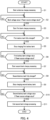
FIG. 4 is a flowchart illustrating a procedure performed by a control apparatus to charge the battery bank unit; -
FIG. 5 is a timing chart for the procedure in the flowchart inFIG. 4 ; -
FIG. 6 is a flowchart illustrating a procedure performed by the control apparatus to calculate remaining time; and -
FIG. 7 illustrates a second table. - Hereinafter, a battery bank unit according to an embodiment of the present disclosure will be described with reference to the accompanying drawings.
FIG. 1 is a schematic diagram illustratingbattery bank unit 1 in an embodiment of the present disclosure.Battery bank unit 1 supplies power to load apparatus 3 connected toexternal power source 2 whenexternal power source 2 loses power.Battery bank unit 1 is charged by power fromexternal power source 2. -
External power source 2 is, for example, an apparatus that converts commercial AC power into DC power and outputs the DC power. Load apparatus 3 is an apparatus (e.g., server apparatus) that operates with DC power. - As illustrated in
FIG. 1 ,battery bank unit 1 includes input/output terminal 10, first andsecond battery banks discharge circuitry 40, andcontrol apparatus 50. - Input/
output terminal 10 is connected topower line 4 that supplies power to load apparatus 3 fromexternal power source 2. - First and
second battery banks second battery banks second battery banks - Charge/
discharge circuitry 40 functions as circuitry that performs charge and discharge of first andsecond battery banks output terminal 10. Charge/discharge circuitry 40 includes boost DC/DC converter 41,switch 42,first charge switch 43,first discharge switch 44,second charge switch 45, andsecond discharge switch 46. - Boost DC/
DC converter 41 is a power conversion apparatus that boosts power supplied fromexternal power source 2 and outputs the boosted power. - Switch 42 switches a value of voltage applied to first and
second battery banks switch 42, first terminal 42a is connected to an output terminal of boost DC/DC converter 41, andsecond terminal 42b is connected to input/output terminal 10. Additionally,third terminal 42c is connected to first andsecond battery banks second charge switches - When
switch 42 is in the on state, first terminal 42a andthird terminal 42c are connected to each other, and the power outputted from boost DC/DC converter 41 is supplied to first andsecond battery banks second charge switches switch 42 is in the off state,second terminal 42b andthird terminal 42c are connected to each other, and the power outputted fromexternal power source 2 is supplied to first andsecond battery banks second charge switches -
First charge switch 43 allowsfirst battery bank 20 to be charged when in the on state, and does not allowfirst battery bank 20 to be charged when in the off state. Infirst charge switch 43,first terminal 43a is connected tothird terminal 42c ofswitch 42 andsecond terminal 43b is connected to the positive electrode offirst battery bank 20. Note that the negative electrode offirst battery bank 20 is connected to the ground. -
First discharge switch 44 allowsfirst battery bank 20 to discharge when in the on state, and does not allowfirst battery bank 20 to discharge when in the off state. Infirst discharge switch 44,first terminal 44a is connected to the positive electrode offirst battery bank 20 andsecond terminal 44b is connected to input/output terminal 10. -
Second charge switch 45 allowssecond battery bank 30 to be charged when in the on state, and does not allowsecond battery bank 30 to be charged when in the off state. Insecond charge switch 45,first terminal 45a is connected tothird terminal 42c ofswitch 42 andsecond terminal 45b is connected to the positive electrode ofsecond battery bank 30. Note that the negative electrode ofsecond battery bank 30 is connected to the ground. -
Second discharge switch 46 allowssecond battery bank 30 to discharge when in the on state, and does not allowsecond battery bank 30 to discharge when in the off state. Insecond discharge switch 46,first terminal 46a is connected to the positive electrode ofsecond battery bank 30 andsecond terminal 46b is connected to input/output terminal 10. -
FIG. 2 is a block diagram ofbattery bank unit 1. As illustrated inFIG. 2 ,battery bank unit 1 further includescurrent sensor 60,first voltage sensor 61,first temperature sensor 62,second voltage sensor 63, andsecond temperature sensor 64. -
Current sensor 60 detects a value of current flowing in or out ofpower line 4 via input/output terminal 10. To be more specific,current sensor 60 detects a value of current between input/output terminal 10 and connectingpoint 40a of charge/discharge circuitry 40.First voltage sensor 61 detects a voltage value offirst battery bank 20.First temperature sensor 62 detects the temperature offirst battery bank 20. -
Second voltage sensor 63 detects a voltage value ofsecond battery bank 30.Second temperature sensor 64 detects the temperature ofsecond battery bank 30.Current sensor 60,first voltage sensor 61,first temperature sensor 62,second voltage sensor 63, andsecond temperature sensor 64 each transmit the detected value to controlapparatus 50. -
Battery bank unit 1 further includes a third voltage sensor (not illustrated) that detects a power source voltage value that is a voltage value ofexternal power source 2.Control apparatus 50 detects a power outage ofexternal power source 2 based on the power source voltage value detected by the third voltage sensor. -
Control apparatus 50 controls the charge/discharge ofbattery bank unit 1 by controlling the states ofswitches 42 to 46.Control apparatus 50 includesstorage 51.Storage 51 stores first table T1 illustrated inFIG. 3 . - First table T1 is a table that is referred to when
control apparatus 50 calculates remaining time that is the time required to complete the charge ofbattery bank unit 1 to be described later. In first table T1, the temperature, total charge time, and charge stop time are associated with each other. In first table T1, the temperature is divided into six temperature zones in total, and between 0°C and 40°C, there are four zones each including a range of 10°C. Needless to say, the temperature range in each temperature zone and the number of temperature zones are not limited to those illustrated inFIG. 3 . The total charge time and charge stop time will be described later in detail. -
Control apparatus 50 also calculates the state of charge (SOC) ofbattery bank unit 1 by a known method based on the current value detected bycurrent sensor 60. The SOC ofbattery bank unit 1 is a charge rate (%) corresponding to the sum of the charge amounts of first andsecond battery banks - Next, charge control for
battery bank unit 1 performed bycontrol apparatus 50 will be described with reference to the flowchart inFIG. 4 and the timing chart inFIG. 5 . - In a state where the charge control is not started, switch 42 and first and second charge switches 43 and 45 are all in the off state and first and second discharge switches 44 and 46 are both in the on state: accordingly, the discharge of first and
second battery banks second battery banks second battery banks battery bank unit 1 is approximately equal to each of the SOCs of first andsecond battery banks -
Control apparatus 50 starts the charge control when detecting connection toexternal power source 2 or detecting the end of the power outage ofexternal power source 2 based on the detection value of the third voltage sensor. -
Control apparatus 50 starts collective charge processing in S1. The collective charge processing is processing of charging first andsecond battery banks FIG. 5 ,control apparatus 50 switches switch 42 and first and second charge switches 43 and 45 to the on state (time t0) from the state whereswitch 42 and first and second charge switches 43 and 45 are all in the off state and first and second discharge switches 44 and 46 are both in the on state. - First and second discharge switches 44 and 46 remain the on state. This allows
battery bank unit 1 to discharge to load apparatus 3 even whenexternal power source 2 loses power during the collective charge processing. - When the collective charge processing is started (time t0), power is supplied from boost DC/
DC converter 41 to first andsecond battery banks second battery banks - In
FIG. 5 , the solid-line voltage value indicates the voltage value offirst battery bank 20, and the chain-line voltage value indicates the voltage value ofsecond battery bank 30. The voltage values of first andsecond battery banks second battery banks - Next, in S2,
control apparatus 50 determines whether the bank voltage value, which is the voltage value ofbattery bank unit 1, is equal to or greater than the power source voltage value. The bank voltage value is specifically a mean value of the voltage value offirst battery bank 20 and the voltage value ofsecond battery bank 30. Note that the bank voltage value may be either one of the voltage values of first andsecond battery banks - Meanwhile, when the voltage values of first and
second battery banks control apparatus 50 ends the collective charge processing and starts first bank charge processing in S3. - The first bank charge processing is processing of charging only
first battery bank 20. In the first bank charge processing,first battery bank 20 is fully charged at a voltage value higher than the power source voltage value.Second battery bank 30 is not charged in the first bank charge processing. - To be more specific,
control apparatus 50 switchessecond charge switch 45 to the off state andfirst discharge switch 44 to the off state (time t1). As a result, the power of boost DC/DC converter 41 is supplied only tofirst battery bank 20, and the voltage value offirst battery bank 20 further increases from the power source voltage value. In the first bank charge processing,first discharge switch 44 is in the off state andfirst battery bank 20 does not discharge. This makes it possible to prevent application of a voltage value higher than the power source voltage value to load apparatus 3, thereby preventing failure of load apparatus 3, for example. - Meanwhile, the charge of
second battery bank 30 is stopped, and the voltage value ofsecond battery bank 30 gradually decreases due to self-discharge.Second discharge switch 46 is in the on state in first bank charge processing. Thus,second battery bank 30 can discharge to load apparatus 3 even whenexternal power source 2 loses power during the first bank charge processing. - Subsequently,
control apparatus 50 determines whetherfirst battery bank 20 is fully charged in S4. To be more specific,control apparatus 50 determines whether the detection value offirst temperature sensor 62 has reached a predetermined first temperature. The first temperature is a temperature at whichfirst battery bank 20 is fully charged. When the detection value offirst temperature sensor 62 is lower than the first temperature (NO in S4),control apparatus 50 continues to chargefirst battery bank 20 only. - In contrast, when
first battery bank 20 is fully charged and the detection value offirst temperature sensor 62 reaches the first temperature (time t2; YES in S4),control apparatus 50 stops chargingfirst battery bank 20 in S5. - To be more specific,
control apparatus 50 switchesfirst charge switch 43 to the off state (time t2). As a result, the charge offirst battery bank 20 is stopped, and the voltage value offirst battery bank 20 gradually decreases due to self-discharge. At this time, the temperature offirst battery bank 20 is higher than the temperature ofsecond battery bank 30. Thus, the drop amount of the voltage value offirst battery bank 20 per unit time is larger than the drop amount of the voltage value ofsecond battery bank 30 per unit time. - Next, in S6,
control apparatus 50 determines whether the voltage value offirst battery bank 20 is equal to or lower than the power source voltage value. When the voltage value offirst battery bank 20 is higher than the power source voltage value (NO in S6),control apparatus 50 continues the state where first andsecond battery banks - When the voltage value of
first battery bank 20 is equal to or lower than the power source voltage value (time t3; YES in S6), in contrast,control apparatus 50 ends the first bank charge processing and starts second bank charge processing in S7. - The second bank charge processing is processing of charging only
second battery bank 30. In the second bank charge processing,second battery bank 30 is fully charged at a voltage value higher than the power source voltage value.First battery bank 20 is not charged in the second bank charge processing. - To be more specific,
control apparatus 50 switchessecond charge switch 45 to the on state,first discharge switch 44 to the on state, andsecond discharge switch 46 to the off state (time t3). As a result, power is supplied from boost DC/DC converter 41 tosecond battery bank 30 only, and the voltage value ofsecond battery bank 30 increases and exceeds the power source voltage value. In the second bank charge processing,second discharge switch 46 is in the off state andsecond battery bank 30 does not discharge. This makes it possible to prevent application of a voltage value higher than the power source voltage value to load apparatus 3, thereby preventing failure of load apparatus 3, for example. - Meanwhile, the charge of
first battery bank 20 remains stopped, and the voltage value offirst battery bank 20 gradually decreases due to self-discharge.First discharge switch 44 is in the on state in second bank charge processing. Thus,first battery bank 20 can discharge to load apparatus 3 even whenexternal power source 2 loses power during the second bank charge processing. - Then,
control apparatus 50 determines whethersecond battery bank 30 is fully charged in S8. To be more specific,control apparatus 50 determines whether the detection value ofsecond temperature sensor 64 has reached a predetermined second temperature. The second temperature is the temperature at whichsecond battery bank 30 is fully charged. When the detection value ofsecond temperature sensor 64 is lower than the second temperature (NO in S8),control apparatus 50 continues to chargesecond battery bank 30 only. Note that the second temperature may be the same as the first temperature, which is the temperature at whichfirst battery bank 20 is fully charged. - In contrast, when
second battery bank 30 is fully charged and the detection value ofsecond temperature sensor 64 reaches the second temperature (time t4; YES in S8),control apparatus 50 stops chargingsecond battery bank 30 in S9. - To be more specific,
control apparatus 50 switchessecond charge switch 45 to the off state (time t4). Accordingly, the charge ofsecond battery bank 30 is stopped, and the voltage ofsecond battery bank 30 gradually decreases due to self-discharge. At this time, the temperature ofsecond battery bank 30 is higher than the temperature offirst battery bank 20. Thus, the drop amount of the voltage value ofsecond battery bank 30 per unit time is larger than the drop amount of the voltage value offirst battery bank 20 per unit time. - Next, in S10,
control apparatus 50 determines whether the voltage value ofsecond battery bank 30 is equal to or lower than the power source voltage value. When the voltage value ofsecond battery bank 30 is higher than the power source voltage value (NO in S10),control apparatus 50 continues the state where first andsecond battery banks - When the voltage value of
second battery bank 30 is equal to or lower than the power source voltage value (time t5; YES in S10), in contrast,control apparatus 50 ends the second bank charge processing in S11. To be more specific,control apparatus 50 switches switch 42 to the off state andsecond discharge switch 46 to the on state (time t5). This is the end of the charge ofbattery bank unit 1.Control apparatus 50 specifies the SOC ofbattery bank unit 1 at the end of the charge ofbattery bank unit 1 as 100%. - Note that
battery bank unit 1 may include three or more battery banks. In a case of including m battery banks, the m battery banks are collectively charged in the collective charge processing. When the collective charge processing is finished, m battery banks are charged one by one in turn as is the case with the above first and second bank charge processing. - Next, control for calculating remaining time performed by
control apparatus 50 will be described with reference to the flowchart inFIG. 6 . The remaining time is time required to complete the charge ofbattery bank unit 1.Control apparatus 50 calculates the remaining time while performing the charge control described above, which is between time t0 and time t5 inFIG. 5 in particular. - In S20,
control apparatus 50 acquires, from first table T1, the total charge time and charge stop time that are associated with the temperature at the start of the charge ofbattery bank unit 1. The temperature ofbattery bank unit 1 is, for example, the mean temperature of first andsecond battery banks battery bank unit 1 may be either one of the temperatures of first andsecond battery banks Expression 1 to be described later. - The total charge time is the time required for the SOC of
battery bank unit 1 at the start of charge to be 100% from a first charge rate (e.g., 0%), in particular. The total charge time is determined in advance for each temperature zone by actual measurement through experiments and stored in first table T1. The first charge rate is any value used in, for example, an experiment to determine the total charge time stored in first table T1 in advance. In the experiment to determine the total charge time, the collective charge processing and first and second bank charge processing are performed in the above-described manner usingbattery bank unit 1 with the SOC of the first charge rate, and the time required for the SOC ofbattery bank unit 1 to be 100% from the first charge rate is measured as the total charge time. - The charge stop time corresponds to the time from when the charge of
first battery bank 20 is stopped to when the charge ofsecond battery bank 30 is started (i.e., from time t2 to time t3 inFIG. 5 ) in particular. The charge stop time is determined in advance for each temperature zone by actual measurement through experiments and stored in first table T1. In the above experiment to determine the total charge time, the time period in which the charge of the battery banks is stopped during the charge ofbattery bank unit 1 is measured as the charge stop time. - In a case where the temperature of
battery bank unit 1 is 25°C at the start of charge control, for example,control apparatus 50 acquires the total charge time "A3" and charge stop time "B3" that are associated with the temperature "20°C or higher and lower than 30°C" from first table T1 inFIG. 3 . - Subsequently,
control apparatus 50 calculates the remaining time in S21. To be more specific,control apparatus 50 calculates the remaining time at the start of charge, which is the remaining time at the time of starting the charge, usingExpression 1.
[1]
- In
Expression 1, "m" is the number of battery banks. In the present embodiment, m = 2. Ts and Tt are respectively the charge stop time and total charge time acquired from first table T1. So (%) is the SOC ofbattery bank unit 1 at the start of charge control (time t0). α (%) is the first charge rate and is the SOC of a battery bank unit at the start of an experiment to determine the total charge time to be stored in first table T1. - Note that So may be either one of the SOCs of first and
second battery banks control apparatus 50 specifies, as 100%, the SOCs of first andsecond battery banks battery bank unit 1. - The configurations of first and
second battery banks second battery banks FIG. 5 ) is considered to be approximately equal to the time period in which the charge is stopped in the first bank charge processing (between time t2 and time t3 inFIG. 5 ). Thus, in a case wherebattery bank unit 1 includes m battery banks in the experiment to determine the total charge time to be stored in first table T1, the total of the time in which the charge of any of the battery banks is stopped corresponds to a value obtained by multiplying m and the charge stop time (Ts) together. That is, "m × Ts" inExpression 1 corresponds to the total of the time periods in which the charge of any of the battery banks is stopped while the charge ofbattery bank unit 1. - Note that, as described above, in the time period in which the charge is stopped during the charge control of
battery bank unit 1, a battery bank that stops charging does not discharge to load apparatus 3. For example,first battery bank 20 does not discharge between time t2 and time t3 inFIG. 5 . Accordingly, the SOC of the battery bank that stops charging cannot be calculated based on the detection value ofcurrent sensor 60. Thus,control apparatus 50 cannot calculate the time period in which the charge is stopped during the charge control ofbattery bank unit 1 using the SOC. - "(Tt - m × Ts)" in
Expression 1 corresponds to the time obtained by subtracting the total of the time periods in which the charge of any of the battery banks is stopped (m × Ts) from the total charge time (Tt) in the experiment to determine the total charge time to be stored in first table T1 usingbattery bank unit 1 with m battery banks. That is, "(Tt - m × Ts)" inExpression 1 corresponds to the time in which the charge of any of the battery banks is in progress in the time required for the SOC ofbattery bank unit 1 with m battery banks to be 100% from α. - Additionally, "(100 - So) / (100 - α)" is a ratio of the amount of charge for the SOC of
battery bank unit 1 to be 100% from So to the amount of charge for the SOC ofbattery bank unit 1 to be 100% from α. - Thus, "(Tt - m × Ts) × (100 - So) / (100 - α)", which is obtained by multiplying "(Tt - m × Ts)" and "(100 - So) / (100 - α)" together, in
Expression 1 corresponds to the time in which the charge of any of the battery banks is in progress in the time required for the SOC ofbattery bank unit 1 with m battery banks to be 100% from So. - That is, in
Expression 1, "(Tt - m × Ts) × (100 - So) / (100 - α)", which is the time in which the charge of any of the battery banks is in progress in the time required for the SOC ofbattery bank unit 1 with m battery banks to be 100% from So, and "m × Ts", which is the total of the time periods in which the charge of any of the battery banks is stopped, are added together. Thus,Expression 1 is an expression for calculating, as the remaining time at the start of charge, the time from the start to the end of the charge ofbattery bank unit 1 in a case where the SOC ofbattery bank unit 1 with m battery banks is So at the start of the charge in the charge control. -
Control apparatus 50 also indicates the calculated remaining time at the start of charge to load apparatus 3. Load apparatus 3 displays the remaining time at the start of charge on a display section such as a display. This allows an administrator of load apparatus 3 to recognize the time from the start to the completion of the charge ofbattery bank unit 1. - Further,
control apparatus 50 measures the time elapsed from the start of the charge ofbattery bank unit 1 during the charge control.Control apparatus 50 then subtracts the elapsed time from the remaining time at the start of charge calculated in S21 at predetermined time intervals to calculate the remaining time at that time, updates the remaining time to the latest, and indicates the updated remaining time to load apparatus 3. Load apparatus 3 displays the updated remaining time on the display section. - Subsequently, in S22,
control apparatus 50 determines whether the first bank charge processing has ended. When the collective charge processing or the first bank charge processing is in progress (NO in S22),control apparatus 50 continues updating and indicating the remaining time. While performing S22,control apparatus 50 measures the time actually spent for the collective charge processing and the first bank charge processing respectively (hereinafter, referred to as actual collective charge time and actual first bank charge time). - When the first bank charge processing has ended (YES in S22),
control apparatus 50 determines, in S23, whether the remaining time needs to be corrected at the end of the first bank charge processing, i.e., at time t3 inFIG. 5 .Control apparatus 50 determines that the remaining time needs to be corrected at time t3 when the time difference between the remaining time at the start of charge calculated in S21 and revised remaining time at the start to be described below is equal to or greater than a predetermined time difference. - The revised remaining time at the start is the time from the start to the end of charge of
battery bank unit 1 calculated based on the time actually spent to complete the procedure until the first bank charge processing in the charge control. In a case where configurations of a plurality of battery banks are similar to each other, the plurality of battery banks require almost the same time to be charged. Thus, the actual first bank charge time is almost equal to the time actually required for the second bank charge processing. The revised remaining time at the start in the present embodiment is the time obtained by adding the actual collective charge time and the actual first bank charge time multiplied by two together. Note that, in a case of m battery banks, the revised remaining time at the start is the time obtained by adding the actual collective charge time and the actual first bank charge time multiplied by m together. - When the time difference is smaller than the predetermined time difference (NO in S23),
control apparatus 50 does not correct the remaining time at time t3. When the time difference is equal to or greater than the predetermined time difference (YES in S23), in contrast,control apparatus 50 corrects the remaining time at time t3 in S24. To be more specific,control apparatus 50 replaces the remaining time at time t3 (at the end of the first bank charge processing) with the actual first bank charge time. When the remaining time at time t3 is corrected,control apparatus 50 updates the latest remaining time as follows. That is,control apparatus 50 subtracts the time elapsed from time t3 from the actual first bank charge time at predetermined time intervals after time t3 to calculate the remaining time at that time and update the remaining time to the latest.Control apparatus 50 then indicates the updated remaining time to load apparatus 3. - The configurations of first and
second battery banks second battery banks control apparatus 50 can accurately correct the remaining time by replacing the remaining time with the actual first bank charge time at the end of the first bank charge processing, and indicate the corrected remaining time. Note thatcontrol apparatus 50 may correct the remaining time in S24 without determining whether the remaining time needs to be corrected in S23. - Next, in S25,
control apparatus 50 determines whether the second bank charge processing has ended. When the second bank charge processing is in progress (NO in S25),control apparatus 50 continues updating and indicating the remaining time. - When the second bank charge processing has ended (YES in S25),
control apparatus 50 updates first table T1 in S26.Control apparatus 50 updates, based on actual total charge time, the total charge time associated with the temperature ofbattery bank unit 1 at the start of the charge in first table T1. The actual total charge time is the time actually spent from the start to the end of the charge ofbattery bank unit 1 in the charge control. - To be more specific,
control apparatus 50 subtracts the remaining time at the start of charge calculated in S21 from the total charge time acquired in S20, and adds the actual total charge time to the subtracted time to calculate updated total charge time. That is, the updated total charge time is the time obtained by adding the charge time actually spent for the SOC to be 100% from So, which is the SOC at the start of the charge, (actual total charge time) to the charge time from the first charge rate (α) to the SOC at the start of the charge (So), which is calculated by subtracting the remaining time at the start of charge calculated in S21 from the total charge time acquired in S20. In other words, the updated total charge time is the time obtained by revising the total charge time stored in first table T1 using the difference between the measured value (actual total charge time) and the calculated value (remaining time at the start of charge calculated in S21) of the time from the start to the end of the charge ofbattery bank unit 1 in the charge control. -
Control apparatus 50 updates the total charge time associated with the temperature ofbattery bank unit 1 at the start of the charge in first table T1 with the calculated updated total charge time. For example, in the case where the temperature ofbattery bank unit 1 is 25°C at the start of the charge control,control apparatus 50 updates the total charge time "A3" associated with the temperature "20°C or higher and lower than 30°C" in first table T1 with the calculated updated total charge time. - Further,
control apparatus 50 updates the charge stop time associated with the temperature ofbattery bank unit 1 at the start of the charge ofbattery bank unit 1 in first table T1 with actual charge stop time. The actual charge stop time is the time actually spent from when the charge offirst battery bank 20 is stopped to when the charge ofsecond battery bank 30 is started in the charge control. That is, the charge stop time stored in first table T1 is updated with the time in which the charge is actually stopped in the first bank charge processing. - For example, in the case where the temperature of
battery bank unit 1 is 25°C at the start of the charge ofbattery bank unit 1,control apparatus 50 updates the charge stop time "B3" associated with the temperature "20°C or higher and lower than 30°C" in first table T1 with the actual charge stop time. - The actual total charge time and actual charge stop time vary depending on the surroundings of
battery bank unit 1, power source voltage value, temperatures of first andsecond battery banks battery bank unit 1, and degree of deterioration of first andsecond battery banks 20 and 30 (hereinafter, referred to as the surroundings ofbattery bank unit 1, etc.). By updating first table T1 with the updated total charge time and actual charge stop time, it is possible to make the values stored in first table T1 match the surroundings ofbattery bank unit 1, etc. Thus,control apparatus 50 updates first table T1 so as to adapt to a change in the surroundings ofbattery bank unit 1, etc. every time first andsecond battery banks - Upon updating first table T1 in S26,
control apparatus 50 ends the control for calculating the remaining time.Control apparatus 50 also ends the indication of the remaining time. Note thatcontrol apparatus 50 ends the control for calculating the remaining time without updating first table T1 when at least one of first andsecond battery banks battery bank unit 1 due to the power outage ofexternal power source 2. - The present disclosure is not limited to the embodiment described above. Various modifications to the embodiment are also included within the scope of the present disclosure, as long as they do not depart from the spirit of the present disclosure.
- For example,
storage 51 may store a plurality of tables. In the following, a description will be given of a case wherestorage 51 further stores second table T2 inFIG. 7 . In second table T2, the temperature, total charge time, and charge stop time are associated with each other as in first table T1. Values stored as the total charge time and charge stop time in second table T2 are different from those in first table T1. - When calculating the remaining time at the start of charge during the charge control,
control apparatus 50 selects a table from which information is acquired from first and second tables T1 and T2 based on the SOC ofbattery bank unit 1 at the start of the charge. To be more specific,control apparatus 50 selects first table T1 when the SOC ofbattery bank unit 1 at the start of the charge is lower than a predetermined second charge rate (e.g., 90%). Meanwhile,control apparatus 50 selects second table T2 when the SOC ofbattery bank unit 1 at the start of the charge is equal to or higher than the second charge rate. The second charge rate is any value determined based on characteristics ofbattery bank unit 1 during the charge, which will be described later. - For example,
control apparatus 50 selects first table T1 when the SOC ofbattery bank unit 1 is lower than the second charge rate (e.g., 90%), for example 20%, at the start of the charge control afterbattery bank unit 1 is connected toexternal power source 2. - In a case where
battery bank unit 1 is connected toexternal power source 2 and load apparatus 3, the SOC ofbattery bank unit 1 decreases due to self-discharge or the like even without the power outage ofexternal power source 2. In a case where the charge control is determined to start when the SOC ofbattery bank unit 1 decreases to 90%,control apparatus 50 selects second table T2 based on the SOC at the start of the charge control being the second charge rate (90%) or higher. - The SOC of a battery bank affects characteristics such as how the voltage of the battery bank increases and how the temperature of the battery bank increases during the charge. Thus, different SOCs of
battery bank unit 1 at the start of the charge cause different characteristics during the charge such as an amount of increase in the bank voltage value ofbattery bank unit 1 per unit time and an amount of increase in the temperature ofbattery bank unit 1 per unit time; accordingly, the charge rate increase differently. Thus,control apparatus 50 can accurately calculate the remaining time by selecting an appropriate table based on the SOC ofbattery bank unit 1 at the start of the charge. - The configuration of first and
second battery banks - In the case where the configuration of first and
second battery banks Expression 1 is replaced by a term in which the charge stop time and the another charge stop time stored in the tables are added together. - In the case where the configuration of first and
second battery banks FIG. 6 may not be performed. - Further,
control apparatus 50 may perform the first bank charge processing and the second bank charge processing without performing the collective charge processing in the charge control. In this case, S1 and S2 inFIG. 4 are not performed and the actual collective charge time is zero in the calculation of the revised remaining time at the start. -
Battery bank unit 1 may be configured so that first andsecond battery banks battery bank unit 1 need not include first andsecond battery banks battery bank unit 1 itself. That is,battery bank unit 1 may be configured by including input/output terminal 10, charge/discharge circuitry 40,control apparatus 50, andsensors 60 to 64. In this case,battery bank unit 1 can function as a back-up apparatus forexternal power source 2 by retrofitting separately arranged first andsecond battery banks - Further,
storage 51 may be configured separately fromcontrol apparatus 50 and communicable withcontrol apparatus 50. In this case,storage 51 may be communicably connected to controlapparatus 50 via a network such as the Internet. With such a configuration, the information of the table can be shared by a plurality ofbattery bank units 1; furthermore, the table can be updated by the plurality ofbattery bank units 1 so as to store more accurate information. Also,control apparatus 50 may be configured separately frombattery bank unit 1. In this case,control apparatus 50 can remotely controlbattery bank unit 1 and calculate the remaining time via a network such as the Internet. Further,storage 51 may be a non-transitory storage medium that stores a remaining charge time calculation program for calculating the remaining time, andcontrol apparatus 50 may calculate the remaining time as described above by reading and executing the remaining charge time calculation program. - The present disclosure is particularly useful as a battery bank unit.
-
- 1 Battery bank unit
- 20 First battery bank
- 30 Second battery bank
- 50 Control apparatus
- T1 First table
- T2 Second table
Claims (10)
- A battery bank unit (1), comprising:a first battery bank (20) and a second battery bank (30) that are connected in parallel to each other; anda control apparatus (50) that starts charging the second battery bank after the first battery bank is fully charged, wherein,the control apparatus calculates remaining time to complete charge of the battery bank unit based on a temperature of the battery bank unit at a start of the charge of the battery bank unit and a state of charge (SOC) of at least one of the first battery bank and/or the second battery bank at the start of the charge of the battery bank unit.
- The battery bank unit according to Claim 1, wherein,
the control apparatus:is configured to acquire information from a first table in which a temperature, total charge time, and charge stop time are associated with each other, the total charge time being time required from the start to completion of the charge of the battery bank unit, the charge stop time being time required from when charge of the first battery bank is stopped to when charge of the second battery bank is started, andcalculates the remaining time based on the total charge time and the charge stop time that are associated with the temperature of the battery bank unit at the start of the charge of the battery bank unit, and on the SOC of at least one of the first battery bank and/or the second battery bank at the start of the charge of the battery bank unit. - The battery bank unit according to Claim 2, wherein the control apparatus updates the first table based on actual total charge time and actual charge stop time, the actual total charge time being time actually spent from the start to the completion of the charge of the battery bank unit, the actual charge stop time being time actually spent from when the charge of the first battery bank is stopped to when the charge of the second battery bank is started.
- The battery bank unit according to Claim 2 or 3, wherein the control apparatus corrects the remaining time during the charge of the battery bank unit based on actual charge time of the first battery bank that is time actually spent from a start of the charge of the first battery bank to a start of the charge of the second battery bank.
- The battery bank unit according to Claim 4, wherein the control apparatus determines whether to correct the remaining time during the charge of the battery bank unit based on the remaining time calculated at the start of the charge of the battery bank unit, the actual charge time of the first battery bank, and time actually spent from the start of the charge of the battery bank unit to the start of the charge of the first battery bank.
- The battery bank unit according to any one of Claims 2 to 5, wherein,
the control apparatus:is configured to acquire information from a second table in which the temperature, the total charge time, and the charge stop time are associated with each other, the second table being different from the first table,selects a table from which the information is acquired from the first table and the second table based on the SOC of at least one of the first battery bank and/or the second battery bank at the start of the charge of the battery bank unit, andcalculates the remaining time based on the temperature of the battery bank unit and the SOC of at least one of the first battery bank and/or the second battery bank at the start of the charge of the battery bank unit, and the total charge time and the charge stop time that are acquired from the selected table. - The battery bank unit according to any one of Claims 1 to 6, wherein the control apparatus indicates the remaining time to a load apparatus connected to the battery bank unit.
- The battery bank unit according to any one of Claims 1 to 7, wherein,
the control apparatus:performs, upon the start of the charge of the battery bank unit, collective charge for collectively charging the first battery bank and the second battery bank, performs first bank charge for charging only the first battery bank after the collective charge, and performs second bank charge for charging only the second battery bank after the first bank charge, andcalculates, at the start of the charge of the battery bank unit, time from a start of the collective charge to completion of the charge of the battery bank unit after the second bank charge as the remaining time. - A remaining charge time calculation method for a computer to calculate remaining time to complete charge of a battery bank unit (1) including a first battery bank (20) and a second battery bank (30) that is connected in parallel to the first battery bank and starts to be charged after the first battery bank is fully charged, the method comprising:acquiring a temperature of the battery bank unit at a start of the charge of the battery bank unit;acquiring a state of charge (SOC) of at least one of the first battery bank and/or the second battery bank at the start of the charge of the battery bank unit; andcalculating the remaining time based on the temperature and the SOC.
- A remaining charge time calculation program stored in a non-transitory storage medium, wherein, when the program is executed by a computer that controls a battery bank unit (1) including a first battery bank (20) and a second battery bank (30) that is connected in parallel to the first battery bank and starts to be charged after the first battery bank is fully charged, the program is configured to cause the computer to perform operations comprising:acquiring a temperature of the battery bank unit at a start of charge of the battery bank unit,acquiring a state of charge (SOC) of at least one of the first battery bank and/or the second battery bank at the start of the charge of the battery bank unit, andcalculating remaining time to complete the charge of the battery bank unit based on the temperature and the SOC.
Applications Claiming Priority (1)
| Application Number | Priority Date | Filing Date | Title |
|---|---|---|---|
| JP2021181217A JP7773342B2 (en) | 2021-11-05 | 2021-11-05 | Battery bank unit, remaining charge time calculation method, and remaining charge time calculation program |
Publications (1)
| Publication Number | Publication Date |
|---|---|
| EP4178070A1 true EP4178070A1 (en) | 2023-05-10 |
Family
ID=84358847
Family Applications (1)
| Application Number | Title | Priority Date | Filing Date |
|---|---|---|---|
| EP22204750.8A Pending EP4178070A1 (en) | 2021-11-05 | 2022-10-31 | Battery bank unit, remaining charge time calculation method, and remaining charge time calculation program |
Country Status (4)
| Country | Link |
|---|---|
| US (1) | US12567755B2 (en) |
| EP (1) | EP4178070A1 (en) |
| JP (1) | JP7773342B2 (en) |
| CA (1) | CA3180744A1 (en) |
Families Citing this family (3)
| Publication number | Priority date | Publication date | Assignee | Title |
|---|---|---|---|---|
| JP7773343B2 (en) * | 2021-11-05 | 2025-11-19 | Fdk株式会社 | Battery bank unit, remaining charge time calculation method, and remaining charge time calculation program |
| JP7773342B2 (en) | 2021-11-05 | 2025-11-19 | Fdk株式会社 | Battery bank unit, remaining charge time calculation method, and remaining charge time calculation program |
| US12620826B2 (en) * | 2023-03-23 | 2026-05-05 | Dell Products L.P. | Systems and methods for intelligent reactivation of battery cells of battery systems |
Citations (3)
| Publication number | Priority date | Publication date | Assignee | Title |
|---|---|---|---|---|
| US20040135548A1 (en) * | 2002-11-18 | 2004-07-15 | Nobuhiro Takano | Battery charger capable of indicating time remaining to achieve full charge |
| JP2016010250A (en) | 2014-06-25 | 2016-01-18 | Fdk株式会社 | Uninterruptible power supply |
| CN111890986A (en) * | 2020-07-24 | 2020-11-06 | 重庆长安汽车股份有限公司 | Method for estimating residual charging time of power battery based on self-updatable data interpolation |
Family Cites Families (95)
| Publication number | Priority date | Publication date | Assignee | Title |
|---|---|---|---|---|
| JPH0997629A (en) | 1995-09-29 | 1997-04-08 | Sanyo Electric Co Ltd | Plural lithium ion secondary battery charging method |
| US5780991A (en) | 1996-07-26 | 1998-07-14 | Telxon Corporation | Multiple station charging apparatus with single charging power supply for parallel charging |
| JP3323832B2 (en) | 1999-06-08 | 2002-09-09 | インターナショナル・ビジネス・マシーンズ・コーポレーション | Method of controlling charge and discharge of multiple batteries |
| US6307350B1 (en) | 1999-07-30 | 2001-10-23 | Ja Effect, Llc | Rechargeable direct current power source |
| JP2001211558A (en) | 2000-01-27 | 2001-08-03 | Sanyo Electric Co Ltd | How to charge multiple batteries |
| KR100793194B1 (en) | 2001-07-05 | 2008-01-10 | 엘지전자 주식회사 | Multi battery charging method and charging device |
| US6828759B1 (en) | 2003-05-15 | 2004-12-07 | Motorola, Inc. | Circuit for regulating current to multiple batteries in a battery charger |
| JP2005110337A (en) | 2003-09-26 | 2005-04-21 | Sanyo Electric Co Ltd | Multiple battery charger |
| US20070024246A1 (en) | 2005-07-27 | 2007-02-01 | Flaugher David J | Battery Chargers and Methods for Extended Battery Life |
| US7638897B2 (en) | 2005-09-22 | 2009-12-29 | The General Electric Company | Method and system for powering a patient monitoring system |
| JP2007236017A (en) | 2006-02-27 | 2007-09-13 | Toshiba Corp | Battery system |
| FR2901070B1 (en) | 2006-05-11 | 2013-04-26 | Commissariat Energie Atomique | METHOD FOR MANAGING A BATTERY OR A PARK OF RECHARGEABLE BATTERIES UTILIZING THE CHARGING WHIPPING EFFECT |
| WO2007148745A1 (en) | 2006-06-22 | 2007-12-27 | Fdk Corporation | Multi-series accumulation cell, series accumulation cell device, and series cell voltage balance correction circuit |
| JP2008136278A (en) | 2006-11-27 | 2008-06-12 | Matsushita Electric Works Ltd | Charger |
| JP2008295172A (en) | 2007-05-23 | 2008-12-04 | Canon Inc | Battery pack, charging device, and electronic device |
| JP2008295169A (en) | 2007-05-23 | 2008-12-04 | Canon Inc | Battery pack, charging device, and electronic device |
| US8660809B2 (en) | 2008-12-02 | 2014-02-25 | Broadcom Corporation | Method for accurate battery run time estimation utilizing adaptive offset values |
| RU2010134764A (en) | 2009-01-07 | 2013-02-20 | Панасоник Корпорэйшн | METHOD FOR CHARGING A BATTERY ASSEMBLY AND CHARGING SYSTEM FOR A BATTERY |
| US8330420B2 (en) | 2009-04-10 | 2012-12-11 | The Regents Of The University Of Michigan | Dynamically reconfigurable framework for a large-scale battery system |
| FR2948831B1 (en) | 2009-07-31 | 2022-01-28 | Jerome Gilbert | UNIVERSAL SYSTEM TO RECHARGE AT LEAST ONE PORTABLE DEVICE |
| NL2005026C2 (en) | 2010-07-05 | 2012-01-09 | Epyon B V | Charger for a battery, plurality of coupled chargers and method of operating. |
| JP2012085390A (en) | 2010-10-07 | 2012-04-26 | Canon Inc | Electronic device |
| US20120319653A1 (en) | 2011-06-15 | 2012-12-20 | Ajith Kuttannair Kumar | System and method for rechargeable battery |
| US8710800B2 (en) | 2011-07-26 | 2014-04-29 | GM Global Technology Operations LLC | Vehicle battery with cell balancing current paths and method of charging the same |
| WO2013054672A1 (en) | 2011-10-11 | 2013-04-18 | 新神戸電機株式会社 | Lead storage battery system |
| US10297855B2 (en) | 2012-05-29 | 2019-05-21 | Nutech Ventures | Rechargeable multi-cell battery |
| JP5955714B2 (en) | 2012-09-18 | 2016-07-20 | 株式会社東芝 | Battery pack and electric vehicle |
| EP2899843B1 (en) | 2012-09-21 | 2018-07-04 | Nissan Motor Co., Ltd | Charging control device and charging time calculation method |
| US20140253040A1 (en) | 2013-03-07 | 2014-09-11 | Apple Inc. | Preventive balancing technique for battery packs in portable electronic devices |
| JP6222581B2 (en) * | 2013-04-03 | 2017-11-01 | パナソニックIpマネジメント株式会社 | Battery system |
| KR101592200B1 (en) | 2013-08-28 | 2016-02-05 | 주식회사 엘지화학 | Method of Rack Voltage Balancing for Battery Pack Having Rack |
| JP6160473B2 (en) | 2013-12-20 | 2017-07-12 | トヨタ自動車株式会社 | Power storage system |
| KR101534980B1 (en) | 2013-12-24 | 2015-07-07 | 현대자동차주식회사 | Calculating method of charging time |
| WO2015112178A2 (en) | 2014-01-27 | 2015-07-30 | Hewlett-Packard Development Company, L.P. | Voltage regulation for battery strings |
| KR101519780B1 (en) | 2014-03-14 | 2015-05-13 | 현대자동차주식회사 | Control method for battery reservation charge of vehicle |
| US10026998B2 (en) | 2014-05-15 | 2018-07-17 | Ford Global Technologies, Llc | Electric vehicle operation to manage battery capacity |
| JP6090265B2 (en) | 2014-08-29 | 2017-03-08 | トヨタ自動車株式会社 | vehicle |
| US9627897B2 (en) | 2014-10-30 | 2017-04-18 | General Electric Company | String current limited battery charging control |
| WO2016184428A1 (en) * | 2015-05-20 | 2016-11-24 | Channel Enterprises (China) Limited | Charging management apparatus, charging apparatus, and charging management method |
| JP6555739B2 (en) | 2015-06-05 | 2019-08-07 | Fdk株式会社 | Charger |
| WO2017000216A1 (en) | 2015-06-30 | 2017-01-05 | 深圳市大疆创新科技有限公司 | Charging control circuit, charging device, charging system and charging control method |
| EP3197006B1 (en) | 2016-01-21 | 2021-06-16 | Samsung Electronics Co., Ltd. | Apparatus and method of charging battery pack |
| JP6555753B2 (en) | 2016-01-27 | 2019-08-07 | Fdk株式会社 | Charging circuit |
| AU2017201788B2 (en) | 2016-03-16 | 2019-02-07 | Tti (Macao Commercial Offshore) Limited | Power tool battery pack with wireless communication |
| KR20170121628A (en) | 2016-04-25 | 2017-11-02 | 엘에스산전 주식회사 | Electric vehicle charging system and method for charging electric vehicle |
| JP6326452B2 (en) | 2016-06-15 | 2018-05-16 | 本田技研工業株式会社 | Battery state estimation device and battery state estimation method |
| US10069313B2 (en) | 2016-07-10 | 2018-09-04 | Gbatteries Energy Canada Inc. | Modulated pulse charging and discharging of a reconfigurable battery pack |
| CN109565180B (en) | 2016-07-12 | 2023-03-17 | 深圳市大疆创新科技有限公司 | System and method for battery management |
| KR102768966B1 (en) * | 2016-12-19 | 2025-02-18 | 현대자동차주식회사 | Vehicle and control method thereof |
| US11394216B2 (en) | 2017-10-27 | 2022-07-19 | Positec Power Tools (Suzhou) Co., Ltd. | Automatic working system |
| US10778013B2 (en) | 2018-01-10 | 2020-09-15 | Microsoft Technology Licensing, Llc | Distributed battery architecture |
| JP7060383B2 (en) | 2018-01-12 | 2022-04-26 | Fdk株式会社 | Alkaline storage battery charge control method and alkaline storage battery charger |
| US10950902B2 (en) | 2018-01-19 | 2021-03-16 | Myeong-Eun Hwang | Battery management system and battery cell array |
| JP7060435B2 (en) | 2018-04-19 | 2022-04-26 | Fdk株式会社 | Charger with failure detection function and failure detection method |
| JP7101524B2 (en) | 2018-04-19 | 2022-07-15 | Fdk株式会社 | Automatic charger |
| KR102338938B1 (en) | 2018-05-03 | 2021-12-10 | 주식회사 엘지에너지솔루션 | Battery management apparatus, and energy storage system including the same |
| US20200006960A1 (en) | 2018-06-28 | 2020-01-02 | Getac Technology Corporation | Charging device and method thereof |
| JP2020036393A (en) | 2018-08-27 | 2020-03-05 | ヤマハ発動機株式会社 | Method for estimating required charging time, device for estimating required charging time, and electric vehicle |
| KR102587084B1 (en) * | 2018-09-05 | 2023-10-11 | 현대자동차주식회사 | Apparatus and method for providing update of vehicle |
| JP7044671B2 (en) | 2018-09-07 | 2022-03-30 | Fdk株式会社 | Power storage device and charging method |
| US12451714B2 (en) | 2018-10-25 | 2025-10-21 | Semiconductor Energy Laboratory Co., Ltd. | Power storage device and method for operating power storage device |
| JP7227445B2 (en) | 2018-12-06 | 2023-02-22 | Fdk株式会社 | Battery polarity determination circuit, charger, and electronic device |
| JP7084290B2 (en) | 2018-12-07 | 2022-06-14 | Fdk株式会社 | Charger and charging method |
| JP7407367B2 (en) | 2019-08-21 | 2024-01-04 | パナソニックIpマネジメント株式会社 | Management systems, management programs, and electric vehicles |
| KR102743393B1 (en) | 2019-09-06 | 2024-12-16 | 주식회사 엘지에너지솔루션 | Battery management apparatus, battery management method, battery pack and electric vehicle |
| AU2020362049A1 (en) | 2019-10-11 | 2022-05-19 | Ariens Company | Power source and control system for a lawn mower |
| JP7473290B2 (en) | 2020-03-27 | 2024-04-23 | Fdk株式会社 | Battery pack |
| JP7577405B2 (en) | 2020-06-29 | 2024-11-05 | Fdk株式会社 | BACKUP POWER DEVICE AND METHOD FOR CONTROLLING BACKUP POWER DEVICE |
| US11777323B2 (en) | 2020-08-13 | 2023-10-03 | Entrantech Inc. | Sequential power discharge for batteries in a power system |
| US12328020B2 (en) | 2020-08-13 | 2025-06-10 | Entrantech Inc. | System for swappable battery module charging and discharging |
| JP7218071B2 (en) * | 2020-08-19 | 2023-02-06 | 矢崎総業株式会社 | power supply |
| US20220089054A1 (en) | 2020-09-18 | 2022-03-24 | Cummins Inc. | Estimation of charging duration for electric vehicles |
| WO2022078420A1 (en) | 2020-10-16 | 2022-04-21 | Globe (jiangsu) Co., Ltd. | Charger, charging device, energy supply device and control method of charger |
| JP2022097773A (en) | 2020-12-21 | 2022-07-01 | Fdk株式会社 | Power supply |
| JP7497466B2 (en) | 2021-01-27 | 2024-06-10 | 武蔵精密工業株式会社 | Battery management device and battery device management method |
| CA3210925A1 (en) | 2021-02-12 | 2022-08-18 | Fdk Corporation | Backup power supply device |
| WO2022205228A1 (en) * | 2021-03-31 | 2022-10-06 | 宁德时代新能源科技股份有限公司 | Battery remaining charging time estimation method and apparatus, and battery management system |
| JP7154338B1 (en) | 2021-03-31 | 2022-10-17 | 本田技研工業株式会社 | Charge control device and charge control method |
| JP2022169913A (en) | 2021-04-28 | 2022-11-10 | Fdk株式会社 | BACKUP POWER SUPPLY DEVICE AND CHARGE/DISCHARGE CONTROL METHOD |
| KR102897300B1 (en) | 2021-05-31 | 2025-12-05 | 삼성전자주식회사 | Method and apparatus for generating charging path for battery |
| US12576743B2 (en) | 2021-05-31 | 2026-03-17 | Panasonic Intellectual Property Management Co., Ltd. | Charger selection system, charger selection method, and charger selection program |
| CN113553534B (en) | 2021-07-05 | 2024-09-03 | 广州小鹏汽车科技有限公司 | Method and device for calculating remaining time of fast charging, vehicle, and storage medium |
| CN114567028B (en) | 2021-09-13 | 2023-01-03 | 惠州市乐亿通科技有限公司 | Battery system and parallel operation method and device thereof |
| KR102892947B1 (en) | 2021-10-18 | 2025-11-27 | 주식회사 엘지에너지솔루션 | Parallel battery system and method of predicting remaining charge time thereof |
| US12233738B2 (en) * | 2021-11-01 | 2025-02-25 | GM Global Technology Operations LLC | Battery preconditioning systems and methods for electric-drive vehicles |
| JP2023068406A (en) | 2021-11-02 | 2023-05-17 | Fdk株式会社 | Charging method and backup power supply device |
| JP7773342B2 (en) | 2021-11-05 | 2025-11-19 | Fdk株式会社 | Battery bank unit, remaining charge time calculation method, and remaining charge time calculation program |
| JP7579881B2 (en) | 2022-02-08 | 2024-11-08 | 香港時代新能源科技有限公司 | Method for determining charging time, BMS, battery, and electric energy device |
| US20250167331A1 (en) | 2022-02-25 | 2025-05-22 | Panasonic Intellectual Property Management Co., Ltd. | Battery temperature control system, battery temperature control method, and non-transitory computer-readable recording medium |
| US20230382266A1 (en) | 2022-05-26 | 2023-11-30 | Transportation Ip Holdings, Llc | Charge transfer timing system and method |
| US12103422B2 (en) | 2022-05-26 | 2024-10-01 | Transportation Ip Holdings, Llc | Charge transfer timing system and method |
| JP2023177920A (en) | 2022-06-03 | 2023-12-14 | Fdk株式会社 | Power storage control device, power storage device, remaining charging time calculation method, and remaining charging time calculation program |
| EP4429067A4 (en) | 2022-09-15 | 2025-04-23 | LG Energy Solution, Ltd. | Battery management system, battery pack, electric vehicle and battery charging time prediction method |
| US20240140256A1 (en) | 2022-11-02 | 2024-05-02 | GM Global Technology Operations LLC | Estimation of remaining battery charge time in stationary electric vehicles |
| CN116053660B (en) * | 2022-12-07 | 2025-01-07 | 华为数字能源技术有限公司 | Energy storage heating control method, energy storage system and photovoltaic storage system |
-
2021
- 2021-11-05 JP JP2021181217A patent/JP7773342B2/en active Active
-
2022
- 2022-10-31 EP EP22204750.8A patent/EP4178070A1/en active Pending
- 2022-11-01 CA CA3180744A patent/CA3180744A1/en active Pending
- 2022-11-01 US US18/051,631 patent/US12567755B2/en active Active
Patent Citations (3)
| Publication number | Priority date | Publication date | Assignee | Title |
|---|---|---|---|---|
| US20040135548A1 (en) * | 2002-11-18 | 2004-07-15 | Nobuhiro Takano | Battery charger capable of indicating time remaining to achieve full charge |
| JP2016010250A (en) | 2014-06-25 | 2016-01-18 | Fdk株式会社 | Uninterruptible power supply |
| CN111890986A (en) * | 2020-07-24 | 2020-11-06 | 重庆长安汽车股份有限公司 | Method for estimating residual charging time of power battery based on self-updatable data interpolation |
Also Published As
| Publication number | Publication date |
|---|---|
| US12567755B2 (en) | 2026-03-03 |
| US20230141602A1 (en) | 2023-05-11 |
| CA3180744A1 (en) | 2023-05-05 |
| JP7773342B2 (en) | 2025-11-19 |
| JP2023069401A (en) | 2023-05-18 |
Similar Documents
| Publication | Publication Date | Title |
|---|---|---|
| US12567755B2 (en) | Battery bank unit, remaining charge time calculation method, and remaining charge time calculation program | |
| US10365334B2 (en) | Storage battery control device, power storage system, control method, and computer-readable medium | |
| US11214168B2 (en) | Deterioration state computation method and deterioration state computation device | |
| JP5897701B2 (en) | Battery state estimation device | |
| US12117497B2 (en) | Battery status estimation apparatus and battery control apparatus | |
| EP2472278A1 (en) | Power management system | |
| CN102460198A (en) | Battery control apparatus and battery control method | |
| EP3444625A1 (en) | Electricity storage device, electricity storage system, and power supply system | |
| JPWO2017043238A1 (en) | Battery monitoring device | |
| EP3734789A1 (en) | Power storage device, power storage system, power supply system, and control method for power storage device | |
| JP2015195653A (en) | Battery system, charge / discharge control program, charge / discharge control method | |
| WO2014020643A1 (en) | Control method and control device using same | |
| EP4287453A1 (en) | Power storage control apparatus for determining remaining charge time and computing method thereof | |
| JPWO2015056634A1 (en) | Power storage system | |
| JP2023137389A (en) | Battery state estimation device and battery state estimation method | |
| JP2018501613A (en) | Method and apparatus for detecting overcharge of a battery accumulator | |
| US20230144462A1 (en) | Battery bank unit, remaining charge time calculation method, and remaining charge time calculation program | |
| US12429526B2 (en) | Method and apparatus for estimating the available runtime of a battery backup system | |
| KR101736419B1 (en) | Charging method for battery capable of prevent overcharge | |
| JP2015100220A (en) | Multiple battery power supply |
Legal Events
| Date | Code | Title | Description |
|---|---|---|---|
| PUAI | Public reference made under article 153(3) epc to a published international application that has entered the european phase |
Free format text: ORIGINAL CODE: 0009012 |
|
| STAA | Information on the status of an ep patent application or granted ep patent |
Free format text: STATUS: THE APPLICATION HAS BEEN PUBLISHED |
|
| AK | Designated contracting states |
Kind code of ref document: A1 Designated state(s): AL AT BE BG CH CY CZ DE DK EE ES FI FR GB GR HR HU IE IS IT LI LT LU LV MC ME MK MT NL NO PL PT RO RS SE SI SK SM TR |
|
| STAA | Information on the status of an ep patent application or granted ep patent |
Free format text: STATUS: REQUEST FOR EXAMINATION WAS MADE |
|
| 17P | Request for examination filed |
Effective date: 20231109 |
|
| RBV | Designated contracting states (corrected) |
Designated state(s): AL AT BE BG CH CY CZ DE DK EE ES FI FR GB GR HR HU IE IS IT LI LT LU LV MC ME MK MT NL NO PL PT RO RS SE SI SK SM TR |
|
| STAA | Information on the status of an ep patent application or granted ep patent |
Free format text: STATUS: EXAMINATION IS IN PROGRESS |
|
| 17Q | First examination report despatched |
Effective date: 20260408 |