EP4178020A1 - Battery module and battery pack comprising same - Google Patents
Battery module and battery pack comprising same Download PDFInfo
- Publication number
- EP4178020A1 EP4178020A1 EP21903645.6A EP21903645A EP4178020A1 EP 4178020 A1 EP4178020 A1 EP 4178020A1 EP 21903645 A EP21903645 A EP 21903645A EP 4178020 A1 EP4178020 A1 EP 4178020A1
- Authority
- EP
- European Patent Office
- Prior art keywords
- barrier layer
- battery
- battery cell
- battery module
- extension part
- Prior art date
- Legal status (The legal status is an assumption and is not a legal conclusion. Google has not performed a legal analysis and makes no representation as to the accuracy of the status listed.)
- Pending
Links
- 230000004888 barrier function Effects 0.000 claims abstract description 98
- 239000000463 material Substances 0.000 claims description 14
- 239000010445 mica Substances 0.000 claims description 8
- 229910052618 mica group Inorganic materials 0.000 claims description 8
- RNFJDJUURJAICM-UHFFFAOYSA-N 2,2,4,4,6,6-hexaphenoxy-1,3,5-triaza-2$l^{5},4$l^{5},6$l^{5}-triphosphacyclohexa-1,3,5-triene Chemical compound N=1P(OC=2C=CC=CC=2)(OC=2C=CC=CC=2)=NP(OC=2C=CC=CC=2)(OC=2C=CC=CC=2)=NP=1(OC=1C=CC=CC=1)OC1=CC=CC=C1 RNFJDJUURJAICM-UHFFFAOYSA-N 0.000 claims description 5
- 239000003063 flame retardant Substances 0.000 claims description 5
- 239000002210 silicon-based material Substances 0.000 claims description 3
- 230000006835 compression Effects 0.000 description 10
- 238000007906 compression Methods 0.000 description 10
- 238000000034 method Methods 0.000 description 7
- 238000010586 diagram Methods 0.000 description 6
- 239000000853 adhesive Substances 0.000 description 3
- 230000001070 adhesive effect Effects 0.000 description 3
- 230000001934 delay Effects 0.000 description 3
- 230000000694 effects Effects 0.000 description 3
- 238000007789 sealing Methods 0.000 description 3
- 230000000052 comparative effect Effects 0.000 description 2
- 230000008569 process Effects 0.000 description 2
- 239000011347 resin Substances 0.000 description 2
- 229920005989 resin Polymers 0.000 description 2
- 239000004677 Nylon Substances 0.000 description 1
- 230000008901 benefit Effects 0.000 description 1
- 238000006243 chemical reaction Methods 0.000 description 1
- 230000003111 delayed effect Effects 0.000 description 1
- 238000005516 engineering process Methods 0.000 description 1
- 239000010408 film Substances 0.000 description 1
- 230000004927 fusion Effects 0.000 description 1
- 230000005484 gravity Effects 0.000 description 1
- 230000010354 integration Effects 0.000 description 1
- 239000002184 metal Substances 0.000 description 1
- 238000012986 modification Methods 0.000 description 1
- 230000004048 modification Effects 0.000 description 1
- 229920001778 nylon Polymers 0.000 description 1
- 230000001151 other effect Effects 0.000 description 1
- 230000000644 propagated effect Effects 0.000 description 1
- 239000000126 substance Substances 0.000 description 1
- 239000010409 thin film Substances 0.000 description 1
- 238000003466 welding Methods 0.000 description 1
Images


Classifications
-
- H—ELECTRICITY
- H01—ELECTRIC ELEMENTS
- H01M—PROCESSES OR MEANS, e.g. BATTERIES, FOR THE DIRECT CONVERSION OF CHEMICAL ENERGY INTO ELECTRICAL ENERGY
- H01M50/00—Constructional details or processes of manufacture of the non-active parts of electrochemical cells other than fuel cells, e.g. hybrid cells
- H01M50/30—Arrangements for facilitating escape of gases
- H01M50/383—Flame arresting or ignition-preventing means
-
- H—ELECTRICITY
- H01—ELECTRIC ELEMENTS
- H01M—PROCESSES OR MEANS, e.g. BATTERIES, FOR THE DIRECT CONVERSION OF CHEMICAL ENERGY INTO ELECTRICAL ENERGY
- H01M10/00—Secondary cells; Manufacture thereof
- H01M10/60—Heating or cooling; Temperature control
- H01M10/65—Means for temperature control structurally associated with the cells
- H01M10/658—Means for temperature control structurally associated with the cells by thermal insulation or shielding
-
- H—ELECTRICITY
- H01—ELECTRIC ELEMENTS
- H01M—PROCESSES OR MEANS, e.g. BATTERIES, FOR THE DIRECT CONVERSION OF CHEMICAL ENERGY INTO ELECTRICAL ENERGY
- H01M50/00—Constructional details or processes of manufacture of the non-active parts of electrochemical cells other than fuel cells, e.g. hybrid cells
- H01M50/10—Primary casings, jackets or wrappings of a single cell or a single battery
- H01M50/102—Primary casings, jackets or wrappings of a single cell or a single battery characterised by their shape or physical structure
- H01M50/103—Primary casings, jackets or wrappings of a single cell or a single battery characterised by their shape or physical structure prismatic or rectangular
-
- H—ELECTRICITY
- H01—ELECTRIC ELEMENTS
- H01M—PROCESSES OR MEANS, e.g. BATTERIES, FOR THE DIRECT CONVERSION OF CHEMICAL ENERGY INTO ELECTRICAL ENERGY
- H01M50/00—Constructional details or processes of manufacture of the non-active parts of electrochemical cells other than fuel cells, e.g. hybrid cells
- H01M50/20—Mountings; Secondary casings or frames; Racks, modules or packs; Suspension devices; Shock absorbers; Transport or carrying devices; Holders
- H01M50/204—Racks, modules or packs for multiple batteries or multiple cells
- H01M50/207—Racks, modules or packs for multiple batteries or multiple cells characterised by their shape
- H01M50/209—Racks, modules or packs for multiple batteries or multiple cells characterised by their shape adapted for prismatic or rectangular cells
-
- H—ELECTRICITY
- H01—ELECTRIC ELEMENTS
- H01M—PROCESSES OR MEANS, e.g. BATTERIES, FOR THE DIRECT CONVERSION OF CHEMICAL ENERGY INTO ELECTRICAL ENERGY
- H01M50/00—Constructional details or processes of manufacture of the non-active parts of electrochemical cells other than fuel cells, e.g. hybrid cells
- H01M50/20—Mountings; Secondary casings or frames; Racks, modules or packs; Suspension devices; Shock absorbers; Transport or carrying devices; Holders
- H01M50/204—Racks, modules or packs for multiple batteries or multiple cells
- H01M50/207—Racks, modules or packs for multiple batteries or multiple cells characterised by their shape
- H01M50/211—Racks, modules or packs for multiple batteries or multiple cells characterised by their shape adapted for pouch cells
-
- H—ELECTRICITY
- H01—ELECTRIC ELEMENTS
- H01M—PROCESSES OR MEANS, e.g. BATTERIES, FOR THE DIRECT CONVERSION OF CHEMICAL ENERGY INTO ELECTRICAL ENERGY
- H01M50/00—Constructional details or processes of manufacture of the non-active parts of electrochemical cells other than fuel cells, e.g. hybrid cells
- H01M50/20—Mountings; Secondary casings or frames; Racks, modules or packs; Suspension devices; Shock absorbers; Transport or carrying devices; Holders
- H01M50/218—Mountings; Secondary casings or frames; Racks, modules or packs; Suspension devices; Shock absorbers; Transport or carrying devices; Holders characterised by the material
- H01M50/22—Mountings; Secondary casings or frames; Racks, modules or packs; Suspension devices; Shock absorbers; Transport or carrying devices; Holders characterised by the material of the casings or racks
- H01M50/222—Inorganic material
- H01M50/224—Metals
-
- H—ELECTRICITY
- H01—ELECTRIC ELEMENTS
- H01M—PROCESSES OR MEANS, e.g. BATTERIES, FOR THE DIRECT CONVERSION OF CHEMICAL ENERGY INTO ELECTRICAL ENERGY
- H01M50/00—Constructional details or processes of manufacture of the non-active parts of electrochemical cells other than fuel cells, e.g. hybrid cells
- H01M50/20—Mountings; Secondary casings or frames; Racks, modules or packs; Suspension devices; Shock absorbers; Transport or carrying devices; Holders
- H01M50/233—Mountings; Secondary casings or frames; Racks, modules or packs; Suspension devices; Shock absorbers; Transport or carrying devices; Holders characterised by physical properties of casings or racks, e.g. dimensions
- H01M50/24—Mountings; Secondary casings or frames; Racks, modules or packs; Suspension devices; Shock absorbers; Transport or carrying devices; Holders characterised by physical properties of casings or racks, e.g. dimensions adapted for protecting batteries from their environment, e.g. from corrosion
-
- H—ELECTRICITY
- H01—ELECTRIC ELEMENTS
- H01M—PROCESSES OR MEANS, e.g. BATTERIES, FOR THE DIRECT CONVERSION OF CHEMICAL ENERGY INTO ELECTRICAL ENERGY
- H01M50/00—Constructional details or processes of manufacture of the non-active parts of electrochemical cells other than fuel cells, e.g. hybrid cells
- H01M50/20—Mountings; Secondary casings or frames; Racks, modules or packs; Suspension devices; Shock absorbers; Transport or carrying devices; Holders
- H01M50/233—Mountings; Secondary casings or frames; Racks, modules or packs; Suspension devices; Shock absorbers; Transport or carrying devices; Holders characterised by physical properties of casings or racks, e.g. dimensions
- H01M50/242—Mountings; Secondary casings or frames; Racks, modules or packs; Suspension devices; Shock absorbers; Transport or carrying devices; Holders characterised by physical properties of casings or racks, e.g. dimensions adapted for protecting batteries against vibrations, collision impact or swelling
-
- H—ELECTRICITY
- H01—ELECTRIC ELEMENTS
- H01M—PROCESSES OR MEANS, e.g. BATTERIES, FOR THE DIRECT CONVERSION OF CHEMICAL ENERGY INTO ELECTRICAL ENERGY
- H01M50/00—Constructional details or processes of manufacture of the non-active parts of electrochemical cells other than fuel cells, e.g. hybrid cells
- H01M50/20—Mountings; Secondary casings or frames; Racks, modules or packs; Suspension devices; Shock absorbers; Transport or carrying devices; Holders
- H01M50/289—Mountings; Secondary casings or frames; Racks, modules or packs; Suspension devices; Shock absorbers; Transport or carrying devices; Holders characterised by spacing elements or positioning means within frames, racks or packs
- H01M50/291—Mountings; Secondary casings or frames; Racks, modules or packs; Suspension devices; Shock absorbers; Transport or carrying devices; Holders characterised by spacing elements or positioning means within frames, racks or packs characterised by their shape
-
- H—ELECTRICITY
- H01—ELECTRIC ELEMENTS
- H01M—PROCESSES OR MEANS, e.g. BATTERIES, FOR THE DIRECT CONVERSION OF CHEMICAL ENERGY INTO ELECTRICAL ENERGY
- H01M50/00—Constructional details or processes of manufacture of the non-active parts of electrochemical cells other than fuel cells, e.g. hybrid cells
- H01M50/50—Current conducting connections for cells or batteries
- H01M50/572—Means for preventing undesired use or discharge
- H01M50/584—Means for preventing undesired use or discharge for preventing incorrect connections inside or outside the batteries
- H01M50/59—Means for preventing undesired use or discharge for preventing incorrect connections inside or outside the batteries characterised by the protection means
- H01M50/593—Spacers; Insulating plates
-
- H—ELECTRICITY
- H01—ELECTRIC ELEMENTS
- H01M—PROCESSES OR MEANS, e.g. BATTERIES, FOR THE DIRECT CONVERSION OF CHEMICAL ENERGY INTO ELECTRICAL ENERGY
- H01M2220/00—Batteries for particular applications
- H01M2220/20—Batteries in motive systems, e.g. vehicle, ship, plane
-
- Y—GENERAL TAGGING OF NEW TECHNOLOGICAL DEVELOPMENTS; GENERAL TAGGING OF CROSS-SECTIONAL TECHNOLOGIES SPANNING OVER SEVERAL SECTIONS OF THE IPC; TECHNICAL SUBJECTS COVERED BY FORMER USPC CROSS-REFERENCE ART COLLECTIONS [XRACs] AND DIGESTS
- Y02—TECHNOLOGIES OR APPLICATIONS FOR MITIGATION OR ADAPTATION AGAINST CLIMATE CHANGE
- Y02E—REDUCTION OF GREENHOUSE GAS [GHG] EMISSIONS, RELATED TO ENERGY GENERATION, TRANSMISSION OR DISTRIBUTION
- Y02E60/00—Enabling technologies; Technologies with a potential or indirect contribution to GHG emissions mitigation
- Y02E60/10—Energy storage using batteries
Definitions
- the present disclosure relates to a battery module and a battery pack including the same, and more particularly, to a battery module that effectively delays the speed of heat propagation between battery cells, and a battery pack including the same.
- a secondary battery has attracted considerable attention as an energy source for power-driven devices, such as an electric bicycle, an electric vehicle, and a hybrid electric vehicle, as well as an energy source for mobile devices, such as a mobile phone, a digital camera, a laptop computer and a wearable device.
- the middle or large-sized battery module is preferably manufactured so as to have as small a size and weight as possible. For this reason, a prismatic battery, a pouch-type battery or the like, which can be stacked with high integration and has a small weight to capacity ratio, is usually used as a battery cell of the middle or large-sized battery module. Meanwhile, in order to protect the battery cell stack from external impact, heat or vibration, the battery module may include a module frame in which a front surface and rear surface are opened to house the battery cell stack in an internal space.
- Fig. 1 is a perspective view of a conventional battery module.
- Fig. 2 is a top view of a battery cell stack included in a conventional battery module.
- Fig. 3 (a) is a plane view of the region A of Fig. 2 as viewed from above, and Fig. 3 (b) is a cross-sectional view taken along the cut surface B-B of (a).
- the conventional battery module includes a battery cell stack 12 in which a plurality of battery cells 11 are stacked in one direction, module frames 30 and 40 for housing the battery cell stack 12, an end plate 15 for covering the front and rear surfaces of the battery cell stack 12.
- the module frames 30 and 40 include a lower frame 30 for covering the lower and both side surfaces of the battery cell stack 12, and an upper plate 40 for covering the upper surface of the battery cell stack 12.
- the battery cell stack 12 includes a fixing member 17 for fixing the plurality of battery cells 11 to each other, and the fixing member 17 is located at a central part and/or an end part of the battery cell stack 12. Further, a compression pad 20 is located between a pair of battery cells adjacent to each other in the battery cell stack 12.
- the compression pad 20 located in the conventional battery cell stack makes contact with the upper surface or the lower surface of the battery cells 11.
- the compression pad 20 can absorb the impact propagated to adjacent battery cells 11. Further, when the battery cell 11 ignites, the heat propagation speed can be delayed due to the thickness possessed by the compression pad 20. However, when the battery cells 110 ignite, secondary cell ignition may occur due to heat conduction between adjacent battery cells 11 and external heat conduction caused by flames generated in the battery cells 11.
- a battery module comprising: a battery cell stack formed by stacking a plurality of battery cells, and a barrier layer interposed between battery cells adjacent to each other among the plurality of battery cells, wherein the barrier layer includes a body part parallel to the battery cell, and an extension part that is bent at one end of the body part and covers the upper end part of the battery cell.
- the extension part may be formed of a flexible material, and cover upper end parts of at least two battery cells.
- the barrier layer may include a first barrier layer disposed parallel to the battery cell, and a second barrier layer disposed between the first barrier layer and the battery cell, and the second barrier layer may include a body part disposed parallel to the first barrier layer, and an extension part that is bent at one end of the body part and covers the upper end part of the battery cell.
- the first barrier layer is located between a first battery cell and a second battery cell adjacent to each other, the second barrier layer includes a 2-1 barrier layer located between the first barrier layer and the first battery cell, and a 2-2 barrier layer located between the first barrier layer and the second battery cell, and a first extension part of the 2-1 barrier layer and a second extension part of the 2-2 barrier layer may be bent in the same direction.
- the first extension part and the second extension part may overlap each other.
- the body part may include an additional extension part that covers an end part of the battery cell in which the electrode lead is located.
- An opening for passing the electrode lead may be formed in the additional extension part of the body part.
- the barrier layer may be formed of a flame retardant member.
- the first barrier layer may be formed of a silicon material, a mica material, or a mixed material thereof, and the second barrier layer may be formed of a mica material.
- the battery module comprises at least two or more barrier layers, and at least two or more battery cells are located between adjacent barrier layers of the two or more barrier layers.
- the extension parts of the barrier layers adjacent to each other may be bent in mutually different directions.
- a battery pack comprising the above-mentioned battery module.
- the barrier layer formed between a pair of battery cells adjacent to each other in the battery cell stack functions as a flame retardant member, thereby capable of delaying the speed of heat propagation between adjacent battery cells when a battery cell ignites.
- the barrier layer is applied not only to the body part of the battery cell but also to the top part and lead part of the battery cell extending therefrom, thereby capable of delaying the speed of heat propagation into a battery cell in which no flame occurs by cell external flames.
- planar when referred to as “planar”, it means when a target portion is viewed from the upper side, and when referred to as “cross-sectional”, it means when a target portion is viewed from the side of a cross section cut vertically.
- Fig. 4 is a diagram showing a method of forming a battery cell stack according to a comparative example.
- the battery cells 11 in the step of stacking the battery cells 11, they can be stacked by interposing a compression pad 20 between battery cell 11 and battery cell 11 adjacent to each other. After stacking the compression pad 20, stacking of the battery cells 11 can be continuously performed again. At this time, the compression pad 20 may have a constant thickness. The compression pad 20 can play a role in preventing cell swirling and can delay heat propagation to some extent when the cell ignites.
- the battery cells 11 and the compression pad 20 can be stacked to form a battery cell stack, and subsequently, subjected to a lead welding process and a module frame process to form a battery module.
- Fig. 5 is a diagram showing a method of forming a battery cell stack included in a battery module according to an embodiment of the present disclosure.
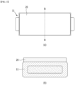
- Fig. 6 is a perspective view showing one battery cell included in the battery cell stack of Fig. 5 .
- the battery cell stack included in the battery module according to the present embodiment is formed by stacking a plurality of battery cells 110, and includes a barrier layer 200 interposed between battery cells 110 adjacent to each other among the plurality of battery cells 110.
- the barrier layer 200 according to the present embodiment includes body parts 200b11 and 200b21 disposed parallel to the battery cells 110, and extension parts 200b12 and 200b22 that are bent at one end of the body parts 200b11 and 200b21 and covers the upper end part of the battery cell 110.
- the barrier layer 200 according to the present embodiment includes a first barrier layer 200a disposed parallel to the battery cell 110, and a second barrier layer 200b disposed between the first barrier layer 200a and the battery cell 110.
- the second barrier layer 200b includes body parts 200b11 and 200b21 disposed parallel to the first barrier layer 200a, and extension parts 200b12 and200b22 that are bent at one end of the body parts 200b11 and 200b21 and cover the upper end part of the battery cell 110.
- the extension parts 200b12 and200b22 may be formed of a flexible material, and cover upper end parts of at least two battery cells 110.
- the first barrier layer 200a is located between a first battery cell 110a and a second battery cell 110b adjacent to each other, and the second barrier layer 200b may include a 2-1 barrier layer 200b1 located between the first barrier layer 200a and the first battery cell 110a, and a 2-2 barrier layer 200b2 located between the first barrier layer 200a and the second battery cell 110b.
- a first extension part 200b12 of the 2-1 barrier layer 200b1 and a second extension part 200b22 of the 2-2 barrier layer 200b2 may be bent in the same direction.
- the first extension part 200b12 and the second extension part 200b22 may overlap each other, and the overlapping part thereof may be an upper end part of at least one battery cell 110.
- the first extension part 200b12 and the second extension part 200b22 cover the upper end part of the battery cell 110 while overlapping each other, thereby capable of cutting off external propagation caused by inter-cell flames.
- the barrier layer 200 is made of a flame retardant member.
- the first barrier layer 200a may be formed of a silicon material, a mica material, or a mixed material thereof, and the second barrier layer 200b may be formed of a mica material.
- the first barrier layer 200a may be formed in the form of a mica sheet, and the second barrier layer 200b may be formed of a thin mica material having a thickness of about 1 mm or less and having a well-bendable form.
- the first barrier layer 200 includes at least two or more, and at least two or more battery cells 110 may be located between two barrier layers 200 adjacent to each other among the barrier layers 200.
- the extension parts of the barrier layers 200 adjacent to each other may be bent in mutually different directions.
- the extension parts included in the barrier layer 200 located on the right side with respect to the two central battery cells 110 are bent in the right direction
- the extension parts included in the barrier layer 200 located on the left side with respect to the two central battery cells 110 may be bent in the left direction.
- the battery cell 110 according to the embodiment of the present disclosure is preferably a pouch-type battery cell.
- the battery cell 110 according to the present embodiment has a structure in which two electrode leads 111 and 112 face each other and protrude from one end part 114a and the other end part 114b of the battery body 113, respectively.
- the battery cell 110 can be produced by adhering both end parts 114a and 114b of a battery case 114 and one side part 114c connecting them in a state in which an electrode assembly (not shown) is housed in the battery case 114.
- the battery cell 110 has a total of three sealing parts 114sa, 114sb and 114sc, and the sealing parts 114sa, 114sb and 114sc have a structure being sealed by a method such as heat fusion, and the other side part may be formed of a connection part 115.
- Between both end parts 114a and 114b of the battery case 114 can be defined in the longitudinal direction of the battery cell 110, and between one side part 114c connecting both end parts 114a and 114b of the battery case 114 and the connection part 115 can be defined in the width direction of the battery cell 110.
- connection part 115 is a region that is extended long along one edge of the battery cell 110, and a protrusion part 110p of the battery cell 110 can be formed at the end part of the connection part 115 and can protrude in a direction perpendicular to the direction in which the connection part 115 extends.
- the protrusion part 110p may be located between one of the sealing parts 114sa and 114sb of both end parts 114a and 114b of the battery case 114 and the connection part 115.
- the battery case 114 generally has a laminate structure of a resin layer/a metal thin film layer/a resin layer.
- a battery cell stack can be formed by attaching an adhesive member such as a cohesive-type adhesive such as a double-sided tape or a chemical adhesive bonded by chemical reaction during adhesion to the surface of the battery case.
- the battery cell stack 120 can be stacked in the y-axis direction.
- Fig. 7 is a diagram showing a state in which a barrier layer is extended in a protruding direction of an electrode lead from a battery cell included in a battery module according to another embodiment of the present disclosure.
- the barrier layer 200 includes a second barrier layer 200b for covering the body part 110C of the battery cell 110 of Fig. 6
- the second barrier layer 200b may include a body part 200b21 disposed parallel to the first barrier layer 200a, and an extension part 200b22 that is bent at one end of the body part 200b21 and covers the upper end part 110T of the battery cell 110, as described above.
- the body part 110C of the battery cell 110 refers to one surface of the battery cell 110 facing the y-axis direction, which is the stacking direction of the battery cells 110, and the upper end part 110T of the battery cell 110 may be a portion corresponding to one side part 114c that connects both end parts 114a and 114b of a battery case 114 in Fig. 6 .
- the upper end part 110T of the battery cell 110 may refer to the upper end part based on the width direction of the battery cell 110.
- the thickness of the body part 200b21 of the second barrier layer 200b may be larger than the thickness of the extension part 200b22 of the second barrier layer 200b.
- the second barrier part 200b can be formed to be relatively thick, thereby increasing the flame retardant performance of interrupting heat propagation between adjacent battery cells 110. Due to the extension part 200b22 of the second barrier part 200b formed to be relatively thin, the occurrence of a gap between the module frame for housing the battery cell stack and the upper end part of the battery cell 110 can be minimized.
- the extension part 200b22 of the second barrier part 200b is formed of a flexible material, so that the double-side folding structure of the upper end of the battery cell 110 can be closely covered.
- the barrier layer 200 may further include a third barrier part 200c for covering an end part of the battery cell 110 around the electrode leads 111 and 112 protruding from the battery cell 110.
- An opening 200D for passing the electrode leads 111 and 112 may be formed in the third barrier layer 200c.
- the third barrier layer 200c may be formed by extending the second barrier layer 200b or may be formed by extending the first barrier layer 200a, or the third barrier layer 200c may be referred to as an 'additional extension part'.
- one or more of the battery modules according to embodiments of the present disclosure can be packaged in a pack case to form a battery pack.
- the above-mentioned battery module and the battery pack including the same can be applied to various devices. These devices can be applied to vehicle means such as an electric bicycle, an electric vehicle, a hybrid vehicle, but the present disclosure is not limited thereto and can be applied to various devices that can use the battery module and the battery pack including the same, which also belongs to the scope of the present disclosure.
Abstract
A battery module according to one embodiment of the present disclosure includes a battery cell stack formed by stacking a plurality of battery cells, and a barrier layer interposed between battery cells adjacent to each other among the plurality of battery cells, wherein the barrier layer includes a body part parallel to the battery cell, and an extension part that is bent at one end of the body part and covers the upper end part of the battery cell.
Description
- This application claims the benefit of
Korean Patent Application No. 10-2020-0169334 filed on December 7, 2020 Korean Patent Application No. 10-2021-0150561 filed on November 4, 2021 - The present disclosure relates to a battery module and a battery pack including the same, and more particularly, to a battery module that effectively delays the speed of heat propagation between battery cells, and a battery pack including the same.
- As technology development and demands for mobile devices increase, the demand for batteries as energy sources is rapidly increasing. In particular, a secondary battery has attracted considerable attention as an energy source for power-driven devices, such as an electric bicycle, an electric vehicle, and a hybrid electric vehicle, as well as an energy source for mobile devices, such as a mobile phone, a digital camera, a laptop computer and a wearable device.
- The middle or large-sized battery module is preferably manufactured so as to have as small a size and weight as possible. For this reason, a prismatic battery, a pouch-type battery or the like, which can be stacked with high integration and has a small weight to capacity ratio, is usually used as a battery cell of the middle or large-sized battery module. Meanwhile, in order to protect the battery cell stack from external impact, heat or vibration, the battery module may include a module frame in which a front surface and rear surface are opened to house the battery cell stack in an internal space.
-
Fig. 1 is a perspective view of a conventional battery module.Fig. 2 is a top view of a battery cell stack included in a conventional battery module.Fig. 3 (a) is a plane view of the region A ofFig. 2 as viewed from above, andFig. 3 (b) is a cross-sectional view taken along the cut surface B-B of (a). - Referring to
Figs. 1 and 2 , the conventional battery module includes abattery cell stack 12 in which a plurality ofbattery cells 11 are stacked in one direction,module frames battery cell stack 12, anend plate 15 for covering the front and rear surfaces of thebattery cell stack 12. Themodule frames lower frame 30 for covering the lower and both side surfaces of thebattery cell stack 12, and anupper plate 40 for covering the upper surface of thebattery cell stack 12. - In addition, the
battery cell stack 12 includes afixing member 17 for fixing the plurality ofbattery cells 11 to each other, and thefixing member 17 is located at a central part and/or an end part of thebattery cell stack 12. Further, acompression pad 20 is located between a pair of battery cells adjacent to each other in thebattery cell stack 12. - Referring to
Figs. 2 and3 , thecompression pad 20 located in the conventional battery cell stack makes contact with the upper surface or the lower surface of thebattery cells 11. Thecompression pad 20 can absorb the impact propagated toadjacent battery cells 11. Further, when thebattery cell 11 ignites, the heat propagation speed can be delayed due to the thickness possessed by thecompression pad 20. However, when thebattery cells 110 ignite, secondary cell ignition may occur due to heat conduction betweenadjacent battery cells 11 and external heat conduction caused by flames generated in thebattery cells 11. - Consequently, it is difficult to sufficiently perform the role of delaying the heat propagation speed by using only the
conventional compression pad 20. Therefore, there is a need to develop a battery module that effectively delays the speed of heat propagation between battery cells unlike the conventional one. - It is an object of the present disclosure to provide a battery module that effectively delays the speed of heat propagation between battery cells, and a battery pack including the same.
- However, the technical problem to be solved by embodiments of the present disclosure is not limited to the above-described problems, and can be variously expanded within the scope of the technical idea included in the present disclosure.
- According to one embodiment of the present disclosure, there is provided a battery module comprising: a battery cell stack formed by stacking a plurality of battery cells, and a barrier layer interposed between battery cells adjacent to each other among the plurality of battery cells, wherein the barrier layer includes a body part parallel to the battery cell, and an extension part that is bent at one end of the body part and covers the upper end part of the battery cell.
- The extension part may be formed of a flexible material, and cover upper end parts of at least two battery cells.
- The barrier layer may include a first barrier layer disposed parallel to the battery cell, and a second barrier layer disposed between the first barrier layer and the battery cell, and the second barrier layer may include a body part disposed parallel to the first barrier layer, and an extension part that is bent at one end of the body part and covers the upper end part of the battery cell.
- The first barrier layer is located between a first battery cell and a second battery cell adjacent to each other, the second barrier layer includes a 2-1 barrier layer located between the first barrier layer and the first battery cell, and a 2-2 barrier layer located between the first barrier layer and the second battery cell, and a first extension part of the 2-1 barrier layer and a second extension part of the 2-2 barrier layer may be bent in the same direction.
- The first extension part and the second extension part may overlap each other.
- The body part may include an additional extension part that covers an end part of the battery cell in which the electrode lead is located.
- An opening for passing the electrode lead may be formed in the additional extension part of the body part.
- The barrier layer may be formed of a flame retardant member.
- The first barrier layer may be formed of a silicon material, a mica material, or a mixed material thereof, and the second barrier layer may be formed of a mica material.
- The battery module comprises at least two or more barrier layers, and at least two or more battery cells are located between adjacent barrier layers of the two or more barrier layers.
- The extension parts of the barrier layers adjacent to each other may be bent in mutually different directions.
- According to another embodiment of the present disclosure, there is provided a battery pack comprising the above-mentioned battery module.
- According to embodiments of the present disclosure, the barrier layer formed between a pair of battery cells adjacent to each other in the battery cell stack functions as a flame retardant member, thereby capable of delaying the speed of heat propagation between adjacent battery cells when a battery cell ignites.
- Further, the barrier layer is applied not only to the body part of the battery cell but also to the top part and lead part of the battery cell extending therefrom, thereby capable of delaying the speed of heat propagation into a battery cell in which no flame occurs by cell external flames.
- The effects of the present disclosure are not limited to the effects mentioned above and additional other effects not described above will be clearly understood from the description of the appended claims by those skilled in the art.
-
-
Fig. 1 is a perspective view of a conventional battery module; -
Fig. 2 is a top view of a battery cell stack contained in a conventional battery module. -
Fig. 3 (a) is a plane view of the region A ofFig. 2 as viewed from above, andFig. 3 (b) is a cross-sectional view taken along the cut surface B-B of (a); -
Fig. 4 is a diagram showing a method of forming a battery cell stack according to a comparative example; -
Fig. 5 is a diagram showing a method of forming a battery cell stack included in a battery module according to an embodiment of the present disclosure; -
Fig. 6 is a perspective view showing one battery cell included in the battery cell stack ofFig. 5 ; and -
Fig. 7 is a diagram showing a state in which a barrier layer is extended in a protruding direction of an electrode lead from a battery cell included in a battery module according to another embodiment of the present disclosure. - Hereinafter, various embodiments of the present disclosure will be described in detail with reference to the accompanying drawings so that those skilled in the art can easily implement them. The present disclosure may be modified in various different ways, and is not limited to the embodiments set forth herein.
- Portions that are irrelevant to the description will be omitted to clearly describe the present disclosure, and like reference numerals designate like elements throughout the specification.
- Further, in the figures, the size and thickness of each element are arbitrarily illustrated for convenience of description, and the present disclosure is not necessarily limited to those illustrated in the figures. In the figures, the thickness of layers, regions, etc. are exaggerated for clarity. In the figures, for convenience of description, the thicknesses of some layers and regions are shown to be exaggerated.
- In addition, it will be understood that when an element such as a layer, film, region, or plate is referred to as being "on" or "above" another element, it can be directly on the other element or intervening elements may also be present. In contrast, when an element is referred to as being "directly on" another element, it means that other intervening elements are not present. Further, the word "on" or "above" means disposed on or below a reference portion, and does not necessarily mean being disposed on the upper end of the reference portion toward the opposite direction of gravity.
- Further, throughout the specification, when a portion is referred to as "including" a certain component, it means that the portion can further include other components, without excluding the other components, unless otherwise stated.
- Further, throughout the specification, when referred to as "planar", it means when a target portion is viewed from the upper side, and when referred to as "cross-sectional", it means when a target portion is viewed from the side of a cross section cut vertically.
-
Fig. 4 is a diagram showing a method of forming a battery cell stack according to a comparative example. - Referring to
Fig. 4 , in the step of stacking thebattery cells 11, they can be stacked by interposing acompression pad 20 betweenbattery cell 11 andbattery cell 11 adjacent to each other. After stacking thecompression pad 20, stacking of thebattery cells 11 can be continuously performed again. At this time, thecompression pad 20 may have a constant thickness. Thecompression pad 20 can play a role in preventing cell swirling and can delay heat propagation to some extent when the cell ignites. Thebattery cells 11 and thecompression pad 20 can be stacked to form a battery cell stack, and subsequently, subjected to a lead welding process and a module frame process to form a battery module. -
Fig. 5 is a diagram showing a method of forming a battery cell stack included in a battery module according to an embodiment of the present disclosure.Fig. 6 is a perspective view showing one battery cell included in the battery cell stack ofFig. 5 . - Referring to
Fig. 5 , the battery cell stack included in the battery module according to the present embodiment is formed by stacking a plurality ofbattery cells 110, and includes abarrier layer 200 interposed betweenbattery cells 110 adjacent to each other among the plurality ofbattery cells 110. Thebarrier layer 200 according to the present embodiment includes body parts 200b11 and 200b21 disposed parallel to thebattery cells 110, and extension parts 200b12 and 200b22 that are bent at one end of the body parts 200b11 and 200b21 and covers the upper end part of thebattery cell 110. Thebarrier layer 200 according to the present embodiment includes afirst barrier layer 200a disposed parallel to thebattery cell 110, and asecond barrier layer 200b disposed between thefirst barrier layer 200a and thebattery cell 110. - The
second barrier layer 200b includes body parts 200b11 and 200b21 disposed parallel to thefirst barrier layer 200a, and extension parts 200b12 and200b22 that are bent at one end of the body parts 200b11 and 200b21 and cover the upper end part of thebattery cell 110. The extension parts 200b12 and200b22 may be formed of a flexible material, and cover upper end parts of at least twobattery cells 110. - More specifically, the
first barrier layer 200a is located between afirst battery cell 110a and asecond battery cell 110b adjacent to each other, and thesecond barrier layer 200b may include a 2-1 barrier layer 200b1 located between thefirst barrier layer 200a and thefirst battery cell 110a, and a 2-2 barrier layer 200b2 located between thefirst barrier layer 200a and thesecond battery cell 110b. At this time, a first extension part 200b12 of the 2-1 barrier layer 200b1 and a second extension part 200b22 of the 2-2 barrier layer 200b2 may be bent in the same direction. At this time, the first extension part 200b12 and the second extension part 200b22 may overlap each other, and the overlapping part thereof may be an upper end part of at least onebattery cell 110. - According to the present embodiment, the first extension part 200b12 and the second extension part 200b22 cover the upper end part of the
battery cell 110 while overlapping each other, thereby capable of cutting off external propagation caused by inter-cell flames. - The
barrier layer 200 according to this embodiment is made of a flame retardant member. At this time, thefirst barrier layer 200a may be formed of a silicon material, a mica material, or a mixed material thereof, and thesecond barrier layer 200b may be formed of a mica material. Thefirst barrier layer 200a may be formed in the form of a mica sheet, and thesecond barrier layer 200b may be formed of a thin mica material having a thickness of about 1 mm or less and having a well-bendable form. - In the battery module according to the present embodiment, the
first barrier layer 200 includes at least two or more, and at least two ormore battery cells 110 may be located between twobarrier layers 200 adjacent to each other among the barrier layers 200. - Further, according to the present embodiment, the extension parts of the barrier layers 200 adjacent to each other may be bent in mutually different directions. For example, as shown in
Fig. 5 , the extension parts included in thebarrier layer 200 located on the right side with respect to the twocentral battery cells 110 are bent in the right direction, and the extension parts included in thebarrier layer 200 located on the left side with respect to the twocentral battery cells 110 may be bent in the left direction. - The
battery cell 110 according to the embodiment of the present disclosure is preferably a pouch-type battery cell. For example, referring toFig. 6 , thebattery cell 110 according to the present embodiment has a structure in which two electrode leads 111 and 112 face each other and protrude from oneend part 114a and theother end part 114b of thebattery body 113, respectively. Thebattery cell 110 can be produced by adhering bothend parts battery case 114 and oneside part 114c connecting them in a state in which an electrode assembly (not shown) is housed in thebattery case 114. In other words, thebattery cell 110 according to the present embodiment has a total of three sealing parts 114sa, 114sb and 114sc, and the sealing parts 114sa, 114sb and 114sc have a structure being sealed by a method such as heat fusion, and the other side part may be formed of aconnection part 115. Between bothend parts battery case 114 can be defined in the longitudinal direction of thebattery cell 110, and between oneside part 114c connecting bothend parts battery case 114 and theconnection part 115 can be defined in the width direction of thebattery cell 110. - The
connection part 115 is a region that is extended long along one edge of thebattery cell 110, and aprotrusion part 110p of thebattery cell 110 can be formed at the end part of theconnection part 115 and can protrude in a direction perpendicular to the direction in which theconnection part 115 extends. Theprotrusion part 110p may be located between one of the sealing parts 114sa and 114sb of bothend parts battery case 114 and theconnection part 115. - The
battery case 114 generally has a laminate structure of a resin layer/a metal thin film layer/a resin layer. For example, when the surface of the battery case is formed of an O (oriented)-nylon layer, it tends to slide easily due to external impact when stacking a plurality of battery cells to form a medium or large-sized battery module. Therefore, in order to prevent this problem and maintain a stable stacked structure of battery cells, a battery cell stack can be formed by attaching an adhesive member such as a cohesive-type adhesive such as a double-sided tape or a chemical adhesive bonded by chemical reaction during adhesion to the surface of the battery case. In the present embodiment, the battery cell stack 120 can be stacked in the y-axis direction. -
Fig. 7 is a diagram showing a state in which a barrier layer is extended in a protruding direction of an electrode lead from a battery cell included in a battery module according to another embodiment of the present disclosure. - On the other hand, in
Fig. 7 and the following description, in order to explain the body part and the extension part of thesecond barrier layer 200b, the reference numerals of the body part 200b21 and the second extension part 200b22 of the 2-2 barrier layer 200b2 described above are used together. However, this is for convenience of explanation only, and the contents described below can also be applied to thebody part 200bfirst 12 of the 2-1 barrier layer 200b1. Further, in the above-mentioned contents, the reference number '200b22' has been described as the second extension part 200b22, but for convenience of explanation, this will be indicated by an 'extension part' in the description ofextension part 200bFig. 7 . - Referring to
Fig. 7 , thebarrier layer 200 according to the present embodiment includes asecond barrier layer 200b for covering thebody part 110C of thebattery cell 110 ofFig. 6 , and thesecond barrier layer 200b may include a body part 200b21 disposed parallel to thefirst barrier layer 200a, and an extension part 200b22 that is bent at one end of the body part 200b21 and covers theupper end part 110T of thebattery cell 110, as described above. - The
body part 110C of thebattery cell 110 refers to one surface of thebattery cell 110 facing the y-axis direction, which is the stacking direction of thebattery cells 110, and theupper end part 110T of thebattery cell 110 may be a portion corresponding to oneside part 114c that connects bothend parts battery case 114 inFig. 6 . In other words, theupper end part 110T of thebattery cell 110 may refer to the upper end part based on the width direction of thebattery cell 110. - At this time, the thickness of the body part 200b21 of the
second barrier layer 200b may be larger than the thickness of the extension part 200b22 of thesecond barrier layer 200b. Thesecond barrier part 200b can be formed to be relatively thick, thereby increasing the flame retardant performance of interrupting heat propagation betweenadjacent battery cells 110. Due to the extension part 200b22 of thesecond barrier part 200b formed to be relatively thin, the occurrence of a gap between the module frame for housing the battery cell stack and the upper end part of thebattery cell 110 can be minimized. In addition, the extension part 200b22 of thesecond barrier part 200b is formed of a flexible material, so that the double-side folding structure of the upper end of thebattery cell 110 can be closely covered. - Referring to
Fig. 7 , thebarrier layer 200 according to the present embodiment may further include athird barrier part 200c for covering an end part of thebattery cell 110 around the electrode leads 111 and 112 protruding from thebattery cell 110. Anopening 200D for passing the electrode leads 111 and 112 may be formed in thethird barrier layer 200c. Thethird barrier layer 200c may be formed by extending thesecond barrier layer 200b or may be formed by extending thefirst barrier layer 200a, or thethird barrier layer 200c may be referred to as an 'additional extension part'. - Meanwhile, one or more of the battery modules according to embodiments of the present disclosure can be packaged in a pack case to form a battery pack.
- The above-mentioned battery module and the battery pack including the same can be applied to various devices. These devices can be applied to vehicle means such as an electric bicycle, an electric vehicle, a hybrid vehicle, but the present disclosure is not limited thereto and can be applied to various devices that can use the battery module and the battery pack including the same, which also belongs to the scope of the present disclosure.
- Although the preferred embodiments of the present disclosure have been described in detail above, the scope of the present disclosure is not limited thereto, and various modifications and improvements made by those skilled in the art using the basic concepts of the present disclosure defined in the following claims also belong to the scope of the present disclosure.
Claims (12)
- A battery module comprising:a battery cell stack formed by stacking a plurality of battery cells, anda barrier layer interposed between battery cells adjacent to each other among the plurality of battery cells,wherein the barrier layer includes a body part parallel to the battery cell, and an extension part that is bent at one end of the body part and covers the upper end part of the battery cell.
- The battery module of claim 1, wherein:
the extension part is formed of a flexible material, and covers upper end parts of at least two battery cells. - The battery module of claim 1, wherein:the barrier layer includes a first barrier layer disposed parallel to the battery cell, and a second barrier layer disposed between the first barrier layer and the battery cell, andthe second barrier layer includes a body part disposed parallel to the first barrier layer, and an extension part that is bent at one end of the body part and covers the upper end part of the battery cell.
- The battery module of claim 3, wherein:the first barrier layer is located between a first battery cell and a second battery cell adjacent to each other, and the second barrier layer includes a 2-1 barrier layer located between the first barrier layer and the first battery cell, and a 2-2 barrier layer located between the first barrier layer and the second battery cell, anda first extension part of the 2-1 barrier layer and a second extension part of the 2-2 barrier layer are bent in the same direction.
- The battery module of claim 4, wherein:
the first extension part and the second extension part overlap each other. - The battery module of claim 1, wherein:
the body part includes an additional extension part that covers an end part of the battery cell in which the electrode lead is located. - The battery module of claim 6, wherein: an opening for passing the electrode lead is formed in the additional extension part of the body part.
- The battery module of claim 1, wherein:
the barrier layer is formed of a flame retardant member. - The battery module of claim 3, wherein: the first barrier layer is formed of a silicon material, a mica material, or a mixed material thereof, and the second barrier layer is formed of a mica material.
- The battery module of claim 1, wherein:the battery module comprises at least two or more barrier layers, andat least two or more battery cells are located between adjacent barrier layers of the two or more barrier layers.
- The battery module of claim 10, wherein:
the extension parts of the barrier layers adjacent to each other are bent in mutually different directions. - A battery pack comprising the battery module of claim 1.
Applications Claiming Priority (3)
| Application Number | Priority Date | Filing Date | Title |
|---|---|---|---|
| KR20200169334 | 2020-12-07 | ||
| KR1020210150561A KR20220080693A (en) | 2020-12-07 | 2021-11-04 | Battery module and battery pack including the same |
| PCT/KR2021/016298 WO2022124598A1 (en) | 2020-12-07 | 2021-11-10 | Battery module and battery pack comprising same |
Publications (1)
| Publication Number | Publication Date |
|---|---|
| EP4178020A1 true EP4178020A1 (en) | 2023-05-10 |
Family
ID=81803423
Family Applications (1)
| Application Number | Title | Priority Date | Filing Date |
|---|---|---|---|
| EP21903645.6A Pending EP4178020A1 (en) | 2020-12-07 | 2021-11-10 | Battery module and battery pack comprising same |
Country Status (5)
| Country | Link |
|---|---|
| US (1) | US20230299416A1 (en) |
| EP (1) | EP4178020A1 (en) |
| JP (1) | JP2023534853A (en) |
| CN (2) | CN114597550A (en) |
| WO (1) | WO2022124598A1 (en) |
Family Cites Families (5)
| Publication number | Priority date | Publication date | Assignee | Title |
|---|---|---|---|---|
| JP2009140786A (en) * | 2007-12-07 | 2009-06-25 | Sekisui Chem Co Ltd | On-board battery pack |
| KR101496523B1 (en) * | 2011-12-08 | 2015-02-26 | 주식회사 엘지화학 | Radiant heat plate for battery cell |
| CN112005429A (en) * | 2017-12-22 | 2020-11-27 | 康明斯公司 | Thermal runaway mitigation system for high-capacity energy battery cell |
| KR102282482B1 (en) * | 2018-02-06 | 2021-07-26 | 주식회사 엘지에너지솔루션 | Battery module and battery pack including the same |
| CN210838029U (en) * | 2019-12-20 | 2020-06-23 | 蜂巢能源科技有限公司 | Power battery pack and vehicle |
-
2021
- 2021-11-10 EP EP21903645.6A patent/EP4178020A1/en active Pending
- 2021-11-10 WO PCT/KR2021/016298 patent/WO2022124598A1/en unknown
- 2021-11-10 JP JP2023504431A patent/JP2023534853A/en active Pending
- 2021-11-10 US US18/017,064 patent/US20230299416A1/en active Pending
- 2021-12-03 CN CN202111468036.9A patent/CN114597550A/en active Pending
- 2021-12-03 CN CN202123034776.XU patent/CN217544739U/en active Active
Also Published As
| Publication number | Publication date |
|---|---|
| US20230299416A1 (en) | 2023-09-21 |
| CN217544739U (en) | 2022-10-04 |
| WO2022124598A1 (en) | 2022-06-16 |
| CN114597550A (en) | 2022-06-07 |
| JP2023534853A (en) | 2023-08-14 |
Similar Documents
| Publication | Publication Date | Title |
|---|---|---|
| EP2654102B1 (en) | Battery stack | |
| EP3923369A1 (en) | Battery module and battery pack comprising same | |
| EP4181289A1 (en) | Battery module and battery pack comprising same | |
| EP4178020A1 (en) | Battery module and battery pack comprising same | |
| EP4131617A1 (en) | Battery module and battery pack including same | |
| EP4170795A1 (en) | Battery module and battery pack including same | |
| KR20220080693A (en) | Battery module and battery pack including the same | |
| EP4109653A1 (en) | Battery module and battery pack including same | |
| US20230198092A1 (en) | Battery module and battery pack including the same | |
| EP4170796A1 (en) | Battery module and battery pack including same | |
| EP4181288A1 (en) | Battery module and battery pack comprising same | |
| US20240136629A1 (en) | Battery module and battery pack including the same | |
| EP4266467A1 (en) | Battery module and battery pack including same | |
| EP4203171A1 (en) | Battery module and battery pack including same | |
| KR20230064246A (en) | Battery module and battery pack including the same | |
| US20220407139A1 (en) | Battery Module and Battery Pack Including the Same | |
| EP4117099A1 (en) | Battery module, battery pack including same, and method of manufacturing battery module | |
| KR20230040125A (en) | Battery module and battery pack including the same | |
| KR20200111531A (en) | Battery module and device including the same |
Legal Events
| Date | Code | Title | Description |
|---|---|---|---|
| STAA | Information on the status of an ep patent application or granted ep patent |
Free format text: STATUS: THE INTERNATIONAL PUBLICATION HAS BEEN MADE |
|
| PUAI | Public reference made under article 153(3) epc to a published international application that has entered the european phase |
Free format text: ORIGINAL CODE: 0009012 |
|
| STAA | Information on the status of an ep patent application or granted ep patent |
Free format text: STATUS: REQUEST FOR EXAMINATION WAS MADE |
|
| 17P | Request for examination filed |
Effective date: 20230131 |
|
| AK | Designated contracting states |
Kind code of ref document: A1 Designated state(s): AL AT BE BG CH CY CZ DE DK EE ES FI FR GB GR HR HU IE IS IT LI LT LU LV MC MK MT NL NO PL PT RO RS SE SI SK SM TR |
|
| DAV | Request for validation of the european patent (deleted) | ||
| DAX | Request for extension of the european patent (deleted) |