EP4178009A2 - Cooling device with cooling sections and stabilized transition sections, battery assembly with cooling device and motor vehicle - Google Patents
Cooling device with cooling sections and stabilized transition sections, battery assembly with cooling device and motor vehicle Download PDFInfo
- Publication number
- EP4178009A2 EP4178009A2 EP22198621.9A EP22198621A EP4178009A2 EP 4178009 A2 EP4178009 A2 EP 4178009A2 EP 22198621 A EP22198621 A EP 22198621A EP 4178009 A2 EP4178009 A2 EP 4178009A2
- Authority
- EP
- European Patent Office
- Prior art keywords
- cooling
- cooling device
- sections
- channel
- transition section
- Prior art date
- Legal status (The legal status is an assumption and is not a legal conclusion. Google has not performed a legal analysis and makes no representation as to the accuracy of the status listed.)
- Pending
Links
- 238000001816 cooling Methods 0.000 title claims abstract description 134
- 230000007704 transition Effects 0.000 title claims abstract description 67
- 230000006641 stabilisation Effects 0.000 claims abstract description 36
- 238000011105 stabilization Methods 0.000 claims abstract description 36
- 239000012809 cooling fluid Substances 0.000 claims abstract description 20
- 230000000087 stabilizing effect Effects 0.000 claims description 5
- 239000012530 fluid Substances 0.000 description 4
- 230000002093 peripheral effect Effects 0.000 description 2
- 230000002411 adverse Effects 0.000 description 1
- 230000001419 dependent effect Effects 0.000 description 1
- 238000011161 development Methods 0.000 description 1
- 230000018109 developmental process Effects 0.000 description 1
- 230000000694 effects Effects 0.000 description 1
- 238000007373 indentation Methods 0.000 description 1
- 239000000463 material Substances 0.000 description 1
- 230000002787 reinforcement Effects 0.000 description 1
Images


Classifications
-
- H—ELECTRICITY
- H01—ELECTRIC ELEMENTS
- H01M—PROCESSES OR MEANS, e.g. BATTERIES, FOR THE DIRECT CONVERSION OF CHEMICAL ENERGY INTO ELECTRICAL ENERGY
- H01M10/00—Secondary cells; Manufacture thereof
- H01M10/60—Heating or cooling; Temperature control
- H01M10/61—Types of temperature control
- H01M10/613—Cooling or keeping cold
-
- F—MECHANICAL ENGINEERING; LIGHTING; HEATING; WEAPONS; BLASTING
- F28—HEAT EXCHANGE IN GENERAL
- F28D—HEAT-EXCHANGE APPARATUS, NOT PROVIDED FOR IN ANOTHER SUBCLASS, IN WHICH THE HEAT-EXCHANGE MEDIA DO NOT COME INTO DIRECT CONTACT
- F28D1/00—Heat-exchange apparatus having stationary conduit assemblies for one heat-exchange medium only, the media being in contact with different sides of the conduit wall, in which the other heat-exchange medium is a large body of fluid, e.g. domestic or motor car radiators
- F28D1/02—Heat-exchange apparatus having stationary conduit assemblies for one heat-exchange medium only, the media being in contact with different sides of the conduit wall, in which the other heat-exchange medium is a large body of fluid, e.g. domestic or motor car radiators with heat-exchange conduits immersed in the body of fluid
- F28D1/03—Heat-exchange apparatus having stationary conduit assemblies for one heat-exchange medium only, the media being in contact with different sides of the conduit wall, in which the other heat-exchange medium is a large body of fluid, e.g. domestic or motor car radiators with heat-exchange conduits immersed in the body of fluid with plate-like or laminated conduits
- F28D1/0308—Heat-exchange apparatus having stationary conduit assemblies for one heat-exchange medium only, the media being in contact with different sides of the conduit wall, in which the other heat-exchange medium is a large body of fluid, e.g. domestic or motor car radiators with heat-exchange conduits immersed in the body of fluid with plate-like or laminated conduits the conduits being formed by paired plates touching each other
-
- F—MECHANICAL ENGINEERING; LIGHTING; HEATING; WEAPONS; BLASTING
- F28—HEAT EXCHANGE IN GENERAL
- F28F—DETAILS OF HEAT-EXCHANGE AND HEAT-TRANSFER APPARATUS, OF GENERAL APPLICATION
- F28F13/00—Arrangements for modifying heat-transfer, e.g. increasing, decreasing
- F28F13/06—Arrangements for modifying heat-transfer, e.g. increasing, decreasing by affecting the pattern of flow of the heat-exchange media
- F28F13/08—Arrangements for modifying heat-transfer, e.g. increasing, decreasing by affecting the pattern of flow of the heat-exchange media by varying the cross-section of the flow channels
-
- H—ELECTRICITY
- H01—ELECTRIC ELEMENTS
- H01M—PROCESSES OR MEANS, e.g. BATTERIES, FOR THE DIRECT CONVERSION OF CHEMICAL ENERGY INTO ELECTRICAL ENERGY
- H01M10/00—Secondary cells; Manufacture thereof
- H01M10/60—Heating or cooling; Temperature control
- H01M10/62—Heating or cooling; Temperature control specially adapted for specific applications
- H01M10/625—Vehicles
-
- H—ELECTRICITY
- H01—ELECTRIC ELEMENTS
- H01M—PROCESSES OR MEANS, e.g. BATTERIES, FOR THE DIRECT CONVERSION OF CHEMICAL ENERGY INTO ELECTRICAL ENERGY
- H01M10/00—Secondary cells; Manufacture thereof
- H01M10/60—Heating or cooling; Temperature control
- H01M10/65—Means for temperature control structurally associated with the cells
- H01M10/655—Solid structures for heat exchange or heat conduction
- H01M10/6556—Solid parts with flow channel passages or pipes for heat exchange
-
- F—MECHANICAL ENGINEERING; LIGHTING; HEATING; WEAPONS; BLASTING
- F28—HEAT EXCHANGE IN GENERAL
- F28D—HEAT-EXCHANGE APPARATUS, NOT PROVIDED FOR IN ANOTHER SUBCLASS, IN WHICH THE HEAT-EXCHANGE MEDIA DO NOT COME INTO DIRECT CONTACT
- F28D21/00—Heat-exchange apparatus not covered by any of the groups F28D1/00 - F28D20/00
- F28D2021/0019—Other heat exchangers for particular applications; Heat exchange systems not otherwise provided for
- F28D2021/0028—Other heat exchangers for particular applications; Heat exchange systems not otherwise provided for for cooling heat generating elements, e.g. for cooling electronic components or electric devices
-
- F—MECHANICAL ENGINEERING; LIGHTING; HEATING; WEAPONS; BLASTING
- F28—HEAT EXCHANGE IN GENERAL
- F28D—HEAT-EXCHANGE APPARATUS, NOT PROVIDED FOR IN ANOTHER SUBCLASS, IN WHICH THE HEAT-EXCHANGE MEDIA DO NOT COME INTO DIRECT CONTACT
- F28D21/00—Heat-exchange apparatus not covered by any of the groups F28D1/00 - F28D20/00
- F28D2021/0019—Other heat exchangers for particular applications; Heat exchange systems not otherwise provided for
- F28D2021/0043—Other heat exchangers for particular applications; Heat exchange systems not otherwise provided for for fuel cells
-
- F—MECHANICAL ENGINEERING; LIGHTING; HEATING; WEAPONS; BLASTING
- F28—HEAT EXCHANGE IN GENERAL
- F28D—HEAT-EXCHANGE APPARATUS, NOT PROVIDED FOR IN ANOTHER SUBCLASS, IN WHICH THE HEAT-EXCHANGE MEDIA DO NOT COME INTO DIRECT CONTACT
- F28D21/00—Heat-exchange apparatus not covered by any of the groups F28D1/00 - F28D20/00
- F28D2021/0019—Other heat exchangers for particular applications; Heat exchange systems not otherwise provided for
- F28D2021/008—Other heat exchangers for particular applications; Heat exchange systems not otherwise provided for for vehicles
-
- F—MECHANICAL ENGINEERING; LIGHTING; HEATING; WEAPONS; BLASTING
- F28—HEAT EXCHANGE IN GENERAL
- F28F—DETAILS OF HEAT-EXCHANGE AND HEAT-TRANSFER APPARATUS, OF GENERAL APPLICATION
- F28F2225/00—Reinforcing means
- F28F2225/04—Reinforcing means for conduits
-
- F—MECHANICAL ENGINEERING; LIGHTING; HEATING; WEAPONS; BLASTING
- F28—HEAT EXCHANGE IN GENERAL
- F28F—DETAILS OF HEAT-EXCHANGE AND HEAT-TRANSFER APPARATUS, OF GENERAL APPLICATION
- F28F2255/00—Heat exchanger elements made of materials having special features or resulting from particular manufacturing processes
- F28F2255/02—Flexible elements
-
- H—ELECTRICITY
- H01—ELECTRIC ELEMENTS
- H01M—PROCESSES OR MEANS, e.g. BATTERIES, FOR THE DIRECT CONVERSION OF CHEMICAL ENERGY INTO ELECTRICAL ENERGY
- H01M10/00—Secondary cells; Manufacture thereof
- H01M10/60—Heating or cooling; Temperature control
- H01M10/65—Means for temperature control structurally associated with the cells
- H01M10/656—Means for temperature control structurally associated with the cells characterised by the type of heat-exchange fluid
- H01M10/6567—Liquids
-
- H—ELECTRICITY
- H01—ELECTRIC ELEMENTS
- H01M—PROCESSES OR MEANS, e.g. BATTERIES, FOR THE DIRECT CONVERSION OF CHEMICAL ENERGY INTO ELECTRICAL ENERGY
- H01M2220/00—Batteries for particular applications
- H01M2220/20—Batteries in motive systems, e.g. vehicle, ship, plane
Definitions
- the invention relates to a cooling device with a base plate which has at least one channel-like depression; a cover plate, which is arranged on the base plate and is connected to the base plate along edges of the channel-like depression in such a way that it tightly closes the channel-like depression, so that a cooling channel is formed, the cover plate depending on a cooling fluid pressure acting in the cooling channel is elastically deformable, wherein the cooling channel has at least two successively arranged cooling sections with a respective first flow cross section, based on the flow direction of a cooling fluid, at least one transition section, which is arranged in particular between two cooling sections.
- Cooling devices of this type are used in particular for cooling battery arrangements, in particular high-voltage batteries, in at least partially electrically driven motor vehicles.
- the object on which the invention is based is seen in specifying a cooling device in which the above disadvantages can be avoided.
- a cooling device with is therefore proposed a base plate having at least one channel-like depression; a cover plate, which is arranged on the base plate and is connected to the base plate along edges of the channel-like depression in such a way that it tightly closes the channel-like depression, so that a cooling channel is formed, the cover plate depending on a cooling fluid pressure acting in the cooling channel is elastically deformable, and wherein the cooling channel has at least two successively arranged cooling sections with a respective first flow cross section and at least one transition section, which is arranged in particular between two cooling sections, based on the flow direction of a cooling fluid.
- At least one stabilization area is provided on the transition section, in which the cover plate and the base plate are at a smaller distance from one another than in the cooling sections, such that the transition section has a second flow cross section, at least in the stabilization area, which differs from the first flow cross section is.
- the base plate and/or the cover plate are brought closer together in a stabilization area.
- This can in particular be caused by a permanent deformation of the base plate and/or the Cover sheet can be achieved.
- a stabilization area forms a kind of narrowing of the cooling channel cross section. Such permanent deformation allows the cooling device to be made stiffer and more stable in the transition section, so that excessive temporary deformation of the cover plate under cooling fluid pressure can be counteracted.
- the stabilization area can be connected to the connection running along edges of the channel-like depression.
- a stabilization section that tapers off the fluid channel can be formed directly next to or possibly even in contact with the edge connections between the base plate and the cover plate.
- the stabilization area can be arranged separately from the connection running along edges of the channel-like depression.
- the stabilization area it is possible for the stabilization area to be formed at a distance from the edge connections between the base plate and the cover plate.
- the stabilization area can be formed essentially over the entire length of the transition section.
- a type of stabilizing or stiffening longitudinal rib can be formed in the cover sheet and/or in the base sheet.
- a number of separate stabilization areas can be distributed in the transition section. For example, several punctiform or circular or short line-like deformations can be provided in the base sheet and/or in the cover sheet, which lead to a stiffening or stabilization of the relevant sheet.
- the cooling sections can be designed essentially in a straight line, the transition section with the stabilization area being arranged in alignment with the cooling sections.
- the cooling sections and the transition section form an aligned or straight fluid channel.
- the transition section a have at least partially curved or curved shape. It is possible, for example, that the transition section is in the form of an arc, the arc ends of which are connected to the cooling sections.
- the arcuate transition section can have an apex which is arranged somewhat higher or lower than the cooling sections. Additional stabilization or stiffening of the transition section can be achieved by an at least partially bent or curved configuration.
- the wall thickness of the base plate can be the same in the cooling sections and in the transition section.
- the wall thickness of the cover plate can be the same in the cooling sections and in the transition section.
- the cooling device has a respective base plate and a respective cover plate, which each have the same or constant thickness, regardless of whether a cooling section or a transition section is formed.
- the base plate and the cover plate can be formed in the stabilizing area in such a way that they touch. Although this reduces the fluid channel cross-section to a greater extent, an additionally stabilized configuration of the transition section can be made possible when the base plate and cover plate touch one another.
- a battery arrangement with at least two battery cell modules arranged next to one another, each of which has a plurality of battery cells, and with a cooling device as described above, which is arranged adjacent to the battery cell modules in such a way that each battery cell module is assigned at least one cooling section and that there is a transition section between two cooling sections is arranged in an edge region of at least one of the battery cell modules.
- the cooling device is arranged in particular below the battery cell modules in such a way that the base plate is lower than the cover plate. In other words, the cover plate faces the battery cell modules and the base plate faces away from them.
- the transition section of the cooling device can bridge a distance that exists between two adjacent battery cell modules. Such a distance forms an area in which the cooling device is not supported by the battery cell modules and the cooling fluid channel forms a kind of bridge from one battery cell module to the adjacent battery cell module.
- the stabilization or reinforcement of the cooling device or the cooling fluid channel can be provided exactly at the point of the battery arrangement at which the cover plate deformed under fluid pressure is not supported by the battery cell modules.
- the cover plate of the cooling device can face the battery cell modules in such a way that the cover plate is at least partially in thermally conductive contact with the battery cell module in question, depending on the prevailing cooling fluid pressure. This enables optimized heat transfer between the battery cell module and the cooling device, in particular cooling fluid.
- a motor vehicle with an at least partially electric drive can be designed with a battery arrangement as described above.
- the battery arrangement with the cooling device can be arranged in such a way that an underbody protection element or underride protection element of the motor vehicle is arranged below the base plate.
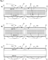
- FIG. 1 are shown in the partial figures A) to C) two battery cell modules 10a, 10b.
- the two battery cell modules 10a, 10b together illustrate a battery arrangement 12, which usually has more than two battery cell modules 10a, 10b.
- Each battery cell module 10a, 10b includes a plurality of battery cells 14 which are arranged as a package in the respective battery cell modules 10a, 10b.
- each cooling channel 18 includes cooling sections 20 and transition sections 22.
- the transition sections are shown hatched for better visibility, although 1 is not a sectional view.
- a cooling channel 18 has at least two successively arranged cooling sections 20, each with the same first flow cross section, and a transition section 22 arranged between two cooling sections 20, based on a flow direction of a cooling fluid indicated by a contour arrow SK.
- a transition section 22 is arranged or formed in particular where the cooling channel 18 is not adjacent to one of the battery cells 14 . Transition sections 22 of the cooling channels are therefore not only possible between two cooling sections 20, but can also be formed at the beginning or end of a cooling channel 18, as is the case on the left-hand side of FIG Figure 1A ) to C) and on the right side of the Figures 1B and C ) can be seen.
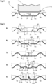
- FIG. 2 shows a simplified sectional view of a cooling channel 18, which is arranged below a battery cell 14 of a battery cell module 10a, 10b not shown. 2 can, for example, about a section line II-II of Figure 1A are equivalent to.
- the cooling channel 18 is part of a cooling device 16 which can have a plurality of such cooling channels 18 .
- the cooling channel 18 or the cooling device 16 is formed by a base plate 24 and a cover plate 26 .
- the base plate 24 has at least one channel-like depression 18v.
- the cover plate 26 is arranged on the base plate 24 .
- the cover plate 26 is connected to the base plate 24 along edges 18r of the channel-like depression 18v in such a way that the channel-like depression 18v closes tightly, so that a relevant cooling channel 18 is formed.
- the cover plate 26 is designed in such a way that it is elastically deformable as a function of a cooling fluid pressure pK acting in the cooling channel 18, which is shown in 2 is indicated by the dashed line of the cover plate 26 and the arrows pK.
- the cover plate 26 of the cooling device 16 faces the battery cells 14 or the battery cell modules 10a, 10b.
- the cover plate 26 n is at least partially in thermally conductive contact with the battery cell 14 in question or the battery cell module 10a, 10b in question, depending on the prevailing cooling fluid pressure pK. In 2 this is indicated by the solid line of the cover plate 26.
- the solid line of the cover plate 26 is not shown in direct contact or in contact with the battery cell 14, because the cover plate 26 would otherwise not be visible. In practical use, however, the cover plate 26 deformed outwards or upwards and the battery cell 14 are in contact, so that effective heat transfer between the battery cell module 10a, 10b and the cooling fluid in the cooling device 16 is made possible.
- the thickness of the base plate 24 is between 0.5 mm and 1.0 mm.
- the thickness of the cover sheet 26 is generally less than that of the base sheet 24.
- the thickness of the cover sheet can be from 0.1 mm to 0.7 mm, preferably 0.3 mm to 0.4 mm.
- FIG. 3 shows in the sub-figures A) to E) simplified and schematic sectional views of the cooling channel 18 in the region of a transition section 22.
- a section can approximately the section line III-III of Figure 1A are equivalent to.
- the cover plate 26 can deform more and less specifically in the transition sections 22 than is the case in the areas of the battery cells 14 .
- At least one stabilization area SB is provided in which the cover plate 26 and the base plate 24 are at a smaller distance AB2 to each other than in the cooling sections 20.
- the usual distance AB1 in the cooling sections 20 between the cover sheet 26 and the base sheet 24 is shown in FIG 2 illustrated.
- the transition section therefore has a second flow cross section, at least in the stabilization region SB, which differs from the first flow cross section of the cooling section 20 ( 2 ) is different.
- the cover plate 26 has deformations 30 directed adjacent to the edges 18r to the channel depression 18v or to the base plate 24 .
- Figure 3B shows a stronger deformation 30 of the cover plate 26 adjacent to the edges 18r and a central or central deformation 32 of the base plate 24 in the direction of the cover plate 26.
- Figure 3C shows a central deformation 30 of the cover plate.
- the example of 3D shows the central or central deformation 30 in the cover sheet 26 and two deformations 32 in the base sheet 24.
- Figure 3E shows a central or central deformation 30 and two laterally arranged deformations 30 in the cover plate 26 and a central or central deformation in the base plate 24.
- the two central or central deformations are designed or pronounced here by way of example that between them the distance AB2 is close to or equal to zero.
- transition sections 22 of the cooling channel 18 thus have respective deformations 30, 32 in the cover plate 26 and/or in the base plate 24, which serve to make the transition section 22 more stable or stiffer. It is thus possible to prevent the transition section, which in many cases is designed to be self-supporting 22 is exposed to unwanted deformations in the assembled state and in operation.
- FIG. 4 shows in partial figures A) to D) simplified and schematic cooling channels 18 with cooling sections 20 and transition sections 22 in a kind of plan view, with deformations 30, 32 in the cover plate 26 and/or in the base plate 26 being illustrated as hatched stabilization areas SB.
- the representations of Figure 4A ) to D) are intended to show in particular that deformations 30, 32 can be provided at different points of the transition section 22.
- FIG. 4A shows stabilization areas SB running along the edges 18r.
- these stabilization areas SB have a contour 34 which faces the cooling channel or cooling fluid and has indentations 36 .
- FIG. 14 shows an example in which the stabilizing area SB is arranged separate from the connection running along edges 18r of the channel-like depression 18v.
- the stabilization area SB for example, as a deformation 30 according to Figure 3C can be understood, arranged centrally or in the middle in the cooling channel 18 or in the transition section 22 .
- Figure 4C shows an example of a possible combination of peripheral stabilization areas SB with a central or central stabilization area SB.
- Such a configuration can have, for example, two peripheral deformations 30 in the cover sheet 26 and a central or central deformation 32 in the base sheet 24, as is the case in FIG Figure 3B is indicated.
- Figure 4D shows an example of stabilization areas SB arranged at certain points. This can involve punctiform deformations 30, 32 in the cover plate 26 and/or in the base plate 24.
- the selective deformations 30, 32 are in particular along the cooling channel 18 or the transition section 22 distributed, the staggered arrangement shown here being merely an example. It is also conceivable merely to have a sequence of centrally arranged selective stabilization areas. It is also conceivable that more than two rows of punctiform stabilization areas SB are provided, for example in such a way that the cover plate 26 can have a golf ball-like structure.
- FIG 5 are simplified and shown schematically two side views of battery cells 14 adjacent battery cell modules 10a, 10b.
- a respective cooling channel 18 of the cooling device 16 is indicated schematically.
- the cooling duct 18 comprises cooling sections 20 and a transition section 22.
- the transition section can have a design in relation to its flow cross section, as is shown in relation to FIG Figures 3 and 4 has been described.
- transition section 22 according to Figure 5A have a straight line.
- the transition sections 22 and the cooling sections 20 are arranged in alignment or in a line with one another, in particular in relation to a height direction Z.
- the transition section 22 has a curved course, as in FIG Figure 5B is illustrated.
- Such a curved or bent profile of the transition section is also somewhat stiffer or more stable than a straight profile.
- the curvature of the transition section does not have to be present over the entire length, as is shown in FIG Figure 5B is indicated. Rather, it is also conceivable for the transition section to have a curvature only in a central or middle region, for example, which is connected to the cooling sections 20 via short, aligned and straight pieces.
- FIG. 6 shows simplified and schematically an at least partially electrically driven motor vehicle 50 with a battery arrangement 12, in particular a high-voltage battery arrangement arranged in the underbody area, the one in the 6 illustrated as a dashed rectangle.
- the cooling device used in such a battery arrangement, which is 6 is not explicitly shown can be implemented in the form described above, ie in particular with transition sections that are stabilized or stiffened in the manner described above by providing or arranging stabilization areas in the transition sections.
Landscapes
- Engineering & Computer Science (AREA)
- Manufacturing & Machinery (AREA)
- Chemical & Material Sciences (AREA)
- Chemical Kinetics & Catalysis (AREA)
- Electrochemistry (AREA)
- General Chemical & Material Sciences (AREA)
- Physics & Mathematics (AREA)
- Thermal Sciences (AREA)
- Mechanical Engineering (AREA)
- General Engineering & Computer Science (AREA)
- Secondary Cells (AREA)
Abstract
Beschrieben wird eine Kühlvorrichtung (16) mit einem Grundblech (24), das wenigstens eine kanalartige Vertiefung (18v) aufweist; einem Deckblech (26), das auf dem Grundblech (24)angeordnet ist und entlang von Rändern (18r) der kanalartigen Vertiefung (18v) derart mit dem Grundblech (24) verbunden ist, dass es die kanalartige Vertiefung (18v) dicht abschließt, so dass ein Kühlkanal (18) gebildet ist, wobei das Deckblech (26) in Abhängigkeit von einem in dem Kühlkanal (18) wirkenden Kühlfluiddruck (pK) elastisch verformbar ist, und wobei der Kühlkanal (18) bezogen auf die Strömungsrichtung (SK) von einem Kühlfluid wenigstens zwei nacheinander angeordnete Kühlabschnitte (20) mit einem jeweils gleichen ersten Strömungsquerschnitt und wenigstens einen Übergangsabschnitt (22) aufweist, der insbesondere zwischen zwei Kühlabschnitten (20) angeordnet ist. Dabei ist vorgesehen, dass an dem Übergangsabschnitt (22) wenigstens ein Stabilisierungsbereich (SB) vorgesehen ist, in dem das Deckblech (26) und das Grundblech (24) einen geringeren Abstand (AB2) zueinander aufweisen als in den Kühlabschnitten (20), derart dass der Übergangsabschnitt (22) zumindest in dem Stabilisierungsbereich (SB) einen zweiten Strömungsquerschnitt aufweist, der von dem ersten Strömungsquerschnitt verschieden ist. Ferner werden eine Batterieanordnung mit einer solchen Kühlvorrichtung und ein Kraftfahrzeug mit einer solchen Batterieanordnung beschrieben.Described is a cooling device (16) with a base plate (24) which has at least one channel-like depression (18v); a cover plate (26) which is arranged on the base plate (24) and is connected to the base plate (24) along edges (18r) of the channel-like depression (18v) in such a way that it tightly closes the channel-like depression (18v), so that a cooling duct (18) is formed, with the cover plate (26) being elastically deformable as a function of a cooling fluid pressure (pK) acting in the cooling duct (18), and with the cooling duct (18) relative to the direction of flow (SK) of a Cooling fluid has at least two successively arranged cooling sections (20) each having the same first flow cross section and at least one transition section (22) which is arranged in particular between two cooling sections (20). At least one stabilization area (SB) is provided on the transition section (22), in which the cover plate (26) and the base plate (24) are at a smaller distance (AB2) from one another than in the cooling sections (20), such that the transition section (22) has a second flow cross section, at least in the stabilization area (SB), which differs from the first flow cross section. Furthermore, a battery arrangement with such a cooling device and a motor vehicle with such a battery arrangement are described.
Description
Die Erfindung betrifft eine Kühlvorrichtung mit einem Grundblech, das wenigstens eine kanalartige Vertiefung aufweist; einem Deckblech, das auf dem Grundblech angeordnet ist und entlang von Rändern der kanalartigen Vertiefung derart mit dem Grundblech verbunden ist, dass es die kanalartige Vertiefung dicht abschließt, so dass ein Kühlkanal gebildet ist, wobei das Deckblech in Abhängigkeit von einem in dem Kühlkanal wirkenden Kühlfluiddruck elastisch verformbar ist, wobei der Kühlkanal bezogen auf die Strömungsrichtung von einem Kühlfluid wenigstens zwei nacheinander angeordnete Kühlabschnitte mit einem jeweils gleichen ersten Strömungsquerschnitt wenigstens einen Übergangsabschnitt aufweist, der insbesondere zwischen zwei Kühlabschnitten angeordnet ist.The invention relates to a cooling device with a base plate which has at least one channel-like depression; a cover plate, which is arranged on the base plate and is connected to the base plate along edges of the channel-like depression in such a way that it tightly closes the channel-like depression, so that a cooling channel is formed, the cover plate depending on a cooling fluid pressure acting in the cooling channel is elastically deformable, wherein the cooling channel has at least two successively arranged cooling sections with a respective first flow cross section, based on the flow direction of a cooling fluid, at least one transition section, which is arranged in particular between two cooling sections.
Derartige Kühlvorrichtungen werden insbesondere zur Kühlung von Batterieanordnungen, insbesondere Hochvoltbatterien, in zumindest teilweise elektrisch angetriebenen Kraftfahrzeugen eingesetzt. Es wird in diesem Zusammenhang beispielsweise auf die
Bei aktuellen Kühlvorrichtungen mit einem elastisch verformbaren bzw. dehnbaren Deckblech, das in Fachjargon auch als "aufblasbare Deckschicht" bezeichnet werden kann, existieren Bereiche, in denen das Deckblech im ausgedehnten Zustand nicht an einem zu kühlenden Element, insbesondere Batteriezelle bzw. Batteriezellenmodul anliegt und somit abgestützt ist. In solchen Bereichen kann eine übermäßige Verformung des Deckblechs stattfinden, insbesondere auch nach vielen Betriebszyklen der Kühlvorrichtung mit einhergehenden Druckaufbau und Druckabbau in den Kühlfluidkanälen.In current cooling devices with an elastically deformable or stretchable cover plate, which can also be referred to as an "inflatable cover layer" in technical jargon, there are areas in which the cover plate in the expanded state does not rest on an element to be cooled, in particular a battery cell or battery cell module and thus is supported. Excessive deformation of the cover plate can take place in such areas, in particular after many operating cycles of the cooling device with associated pressure build-up and pressure reduction in the cooling fluid channels.
Hierdurch kann eine Schwächung des Materials auftreten mit nachteiligen Auswirkungen auf die Effektivität und Funktionstüchtigkeit der Kühlvorrichtung.This can weaken the material with adverse effects on the effectiveness and functionality of the cooling device.
Die der Erfindung zu Grunde liegende Aufgabe wird darin gesehen, eine Kühlvorrichtung anzugeben, bei der obigen Nachteile vermieden werden können.The object on which the invention is based is seen in specifying a cooling device in which the above disadvantages can be avoided.
Diese Aufgabe wird gelöst durch eine Kühlvorrichtung, eine Batterieanordnung und ein Kraftfahrzeug mit den Merkmalen der jeweiligen unabhängigen Patentansprüche. Vorteilhafte Ausgestaltungen mit zweckmäßigen Weiterbildungen sind in den abhängigen Patentansprüchen angegeben.This object is achieved by a cooling device, a battery arrangement and a motor vehicle having the features of the respective independent patent claims. Advantageous configurations with expedient developments are specified in the dependent patent claims.
Vorgeschlagen wird also eine Kühlvorrichtung mit
einem Grundblech, das wenigstens eine kanalartige Vertiefung aufweist; einem Deckblech, das auf dem Grundblech angeordnet ist und entlang von Rändern der kanalartigen Vertiefung derart mit dem Grundblech verbunden ist, dass es die kanalartige Vertiefung dicht abschließt, so dass ein Kühlkanal gebildet ist, wobei das Deckblech in Abhängigkeit von einem in dem Kühlkanal wirkenden Kühlfluiddruck elastisch verformbar ist, und wobei der Kühlkanal bezogen auf die Strömungsrichtung von einem Kühlfluid wenigstens zwei nacheinander angeordnete Kühlabschnitte mit einem jeweils gleichen ersten Strömungsquerschnitt und wenigstens einen Übergangsabschnitt aufweist, der insbesondere zwischen zwei Kühlabschnitten angeordnet ist. Dabei ist vorgesehen, dass an dem Übergangsabschnitt wenigstens ein Stabilisierungsbereich vorgesehen ist, in dem das Deckblech und das Grundblech einen geringeren Abstand zueinander aufweisen als in den Kühlabschnitten, derart dass der Übergangsabschnitt zumindest in dem Stabilisierungsbereich einen zweiten Strömungsquerschnitt aufweist, der von dem ersten Strömungsquerschnitt verschieden ist.A cooling device with is therefore proposed
a base plate having at least one channel-like depression; a cover plate, which is arranged on the base plate and is connected to the base plate along edges of the channel-like depression in such a way that it tightly closes the channel-like depression, so that a cooling channel is formed, the cover plate depending on a cooling fluid pressure acting in the cooling channel is elastically deformable, and wherein the cooling channel has at least two successively arranged cooling sections with a respective first flow cross section and at least one transition section, which is arranged in particular between two cooling sections, based on the flow direction of a cooling fluid. It is provided that at least one stabilization area is provided on the transition section, in which the cover plate and the base plate are at a smaller distance from one another than in the cooling sections, such that the transition section has a second flow cross section, at least in the stabilization area, which differs from the first flow cross section is.
Mit anderen Worten sind das Grundblech oder/und das Deckblech in einem Stabilisierungsbereich einander angenähert. Dies kann insbesondere durch eine dauerhaft vorgesehene Verformung des Grundblechs oder/und des Deckblechs erreicht werden. Dabei bildet ein Stabilisierungsbereich eine Art Verjüngung des Kühlkanalquerschnitts. Durch eine derartige dauerhafte Verformung kann die Kühlvorrichtung im Übergangsabschnitt steifer und stabiler ausgeführt werden, so dass einer übermäßigen temporären Verformung des Deckblechs unter Kühlfluiddruck entgegengewirkt werden kann.In other words, the base plate and/or the cover plate are brought closer together in a stabilization area. This can in particular be caused by a permanent deformation of the base plate and/or the Cover sheet can be achieved. A stabilization area forms a kind of narrowing of the cooling channel cross section. Such permanent deformation allows the cooling device to be made stiffer and more stable in the transition section, so that excessive temporary deformation of the cover plate under cooling fluid pressure can be counteracted.
Bei der Kühlvorrichtung kann sich der Stabilisierungsbereich an die entlang von Rändern der kanalartigen Vertiefung verlaufende Verbindung anschließen. Mit anderen Worten ist es möglich, dass ein den Fluidkanal verjüngender Stabilisierungsabschnitt direkt neben oder ggf. sogar in Kontakt mit den Randverbindungen zwischen Grundblech und Deckblech ausgebildet ist.In the case of the cooling device, the stabilization area can be connected to the connection running along edges of the channel-like depression. In other words, it is possible for a stabilization section that tapers off the fluid channel to be formed directly next to or possibly even in contact with the edge connections between the base plate and the cover plate.
Bei der Kühlvorrichtung kann der Stabilisierungsbereich gesondert von der entlang von Rändern der kanalartigen Vertiefung verlaufenden Verbindung angeordnet sein. Insbesondere ist es möglich, dass der Stabilisierungsbereich mit einem Abstand zu den Randverbindungen zwischen Grundblech und Deckblech ausgebildet ist.In the case of the cooling device, the stabilization area can be arranged separately from the connection running along edges of the channel-like depression. In particular, it is possible for the stabilization area to be formed at a distance from the edge connections between the base plate and the cover plate.
Bei der Kühlvorrichtung kann der Stabilisierungsbereich im Wesentlichen auf der gesamten Länge des Übergangsabschnitts ausgebildet sein. Hierdurch kann beispielsweise eine Art stabilisierende bzw. versteifende Längsrippe im Deckblech oder/und im Grundblech ausgebildet werden.In the case of the cooling device, the stabilization area can be formed essentially over the entire length of the transition section. In this way, for example, a type of stabilizing or stiffening longitudinal rib can be formed in the cover sheet and/or in the base sheet.
Bei der Kühlvorrichtung können im Übergangsabschnitt mehrere gesonderte Stabilisierungsbereiche verteilt angeordnet sein. Beispielsweise können im Grundblech oder/und im Deckblech mehrere punktartige bzw. kreisförmige oder kurze linienartige Verformungen vorgesehen sein, die zu einer Versteifung bzw. Stabilisierung des betreffenden Blechs führen.In the case of the cooling device, a number of separate stabilization areas can be distributed in the transition section. For example, several punctiform or circular or short line-like deformations can be provided in the base sheet and/or in the cover sheet, which lead to a stiffening or stabilization of the relevant sheet.
Bei der Kühlvorrichtung können die Kühlabschnitte im Wesentlichen geradlinig ausgebildet sein, wobei der Übergangsabschnitt mit den Stabilisierungsbereich fluchtend zu den Kühlabschnitten angeordnet ist. Mit anderen Worten bilden die Kühlabschnitte und der Übergangsabschnitt einen fluchtenden bzw. geradlinigen Fluidkanal. Alternativ kann der Übergangsabschnitt eine zumindest teilweise gekrümmte oder gebogene Form aufweisen. Es ist beispielsweise möglich, dass der Übergangsabschnitt in der Form eines Bogens ausgebildet ist, dessen Bogenenden mit den Kühlabschnitten verbunden sind. Dabei kann der bogenförmige Übergangsabschnitt einen Scheitelpunkt aufweisen, der etwas höher bzw. tiefer als die Kühlabschnitte angeordnet ist. Durch eine zumindest teilweise gebogene bzw. gekrümmte Ausgestaltung kann eine zusätzliche Stabilisierung bzw. Versteifung des Übergangsabschnitts erreicht werden.In the case of the cooling device, the cooling sections can be designed essentially in a straight line, the transition section with the stabilization area being arranged in alignment with the cooling sections. In other words, the cooling sections and the transition section form an aligned or straight fluid channel. Alternatively, the transition section a have at least partially curved or curved shape. It is possible, for example, that the transition section is in the form of an arc, the arc ends of which are connected to the cooling sections. In this case, the arcuate transition section can have an apex which is arranged somewhat higher or lower than the cooling sections. Additional stabilization or stiffening of the transition section can be achieved by an at least partially bent or curved configuration.
Bei der Kühlvorrichtung kann die Wandstärke des Grundblechs in den Kühlabschnitten und in dem Übergangsabschnitt gleich sein. Ferner kann bei der Kühlvorrichtung die Wandstärke des Deckblechs in den Kühlabschnitten und in dem Übergangsabschnitt gleich sein. Mit anderen Worten weist die Kühlvorrichtung ein jeweiliges Grundblech und ein jeweiliges Deckblech auf, die jeweils eine gleiche bzw. konstante Dicke aufweisen, unabhängig davon, ob ein Kühlabschnitt oder ein Übergangsabschnitt gebildet ist.In the case of the cooling device, the wall thickness of the base plate can be the same in the cooling sections and in the transition section. Furthermore, in the case of the cooling device, the wall thickness of the cover plate can be the same in the cooling sections and in the transition section. In other words, the cooling device has a respective base plate and a respective cover plate, which each have the same or constant thickness, regardless of whether a cooling section or a transition section is formed.
Bei der Kühlvorrichtung können das Grundblech und das Deckblech in dem Stabilisierungsbereich derart ausgebildet sein, dass sie sich berühren. Hierdurch wird zwar der Fluidkanalquerschnitt stärker verkleinert, aber bei sich berührendem Grundblech und Deckblech kann eine zusätzlich stabilisierte Ausgestaltung des Übergangsabschnitts ermöglicht werden.In the cooling device, the base plate and the cover plate can be formed in the stabilizing area in such a way that they touch. Although this reduces the fluid channel cross-section to a greater extent, an additionally stabilized configuration of the transition section can be made possible when the base plate and cover plate touch one another.
Vorgeschlagen wird auch eine Batterieanordnung mit wenigstens zwei nebeneinander angeordneten Batteriezellenmodulen, die jeweils mehrere Batteriezellen aufweisen, und mit einer oben beschriebenen Kühlvorrichtung, die angrenzend an die Batteriezellenmodule angeordnet ist, derart dass jedem Batteriezellenmodul wenigstens ein Kühlabschnitt zugeordnet ist und dass ein zwischen zwei Kühlabschnitten vorhandener Übergangsabschnitt in einem Randbereich von wenigstens einem der Batteriezellenmodule angeordnet ist. Dabei ist die Kühlvorrichtung insbesondere unterhalb der Batteriezellenmodule angeordnet, derart, dass das Grundblech tiefer liegt als das Deckblech. Anders ausgedrückt ist das Deckblech den Batteriezellenmodulen zugewandt und das Grundblech ist von diesen abgewandt.Also proposed is a battery arrangement with at least two battery cell modules arranged next to one another, each of which has a plurality of battery cells, and with a cooling device as described above, which is arranged adjacent to the battery cell modules in such a way that each battery cell module is assigned at least one cooling section and that there is a transition section between two cooling sections is arranged in an edge region of at least one of the battery cell modules. In this case, the cooling device is arranged in particular below the battery cell modules in such a way that the base plate is lower than the cover plate. In other words, the cover plate faces the battery cell modules and the base plate faces away from them.
Bei der Batterieanordnung kann der Übergangsabschnitt der Kühlvorrichtung einen zwischen zwei benachbarten Batteriezellenmodulen vorhandenen Abstand überbrücken. Ein solcher Abstand bildet einen Bereich, in dem die Kühlvorrichtung nicht durch die Batteriezellenmodule abgestützt ist und der Kühlfluidkanal eine Art Brücke von dem einen Batteriezellenmodul zu dem benachbarten Batteriezellenmodul bildet. Durch die Anordnung des Übergangsabschnitts mit dem wenigstens einen Stabilisierungsbereich genau zwischen zwei benachbarten Batteriezellenmodulen kann die Stabilisierung bzw. Versteifung der Kühlvorrichtung bzw. des Kühlfluidkanals genau an der Stelle der Batterieanordnung bereitgestellt werden, an der das unter Fluiddruck verformte Deckblech nicht durch die Batteriezellenmodule abgestützt ist.In the battery arrangement, the transition section of the cooling device can bridge a distance that exists between two adjacent battery cell modules. Such a distance forms an area in which the cooling device is not supported by the battery cell modules and the cooling fluid channel forms a kind of bridge from one battery cell module to the adjacent battery cell module. By arranging the transition section with the at least one stabilization area exactly between two adjacent battery cell modules, the stabilization or reinforcement of the cooling device or the cooling fluid channel can be provided exactly at the point of the battery arrangement at which the cover plate deformed under fluid pressure is not supported by the battery cell modules.
Bei der Batterieanordnung kann das Deckblech der Kühlvorrichtung den Batteriezellenmodulen derart zugewandt sein, dass das Deckbleck in Abhängigkeit von dem herrschenden Kühlfluiddruck zumindest teilweise in wärmeleitendem Kontakt mit dem betreffenden Batteriezellenmodul steht. Hierdurch wird eine optimierte Wärmeübertragung zwischen Batteriezellenmodul und Kühlvorrichtung, insbesondere Kühlfluid ermöglicht.In the battery arrangement, the cover plate of the cooling device can face the battery cell modules in such a way that the cover plate is at least partially in thermally conductive contact with the battery cell module in question, depending on the prevailing cooling fluid pressure. This enables optimized heat transfer between the battery cell module and the cooling device, in particular cooling fluid.
Ein Kraftfahrzeug mit zumindest teilweise elektrischem Antrieb kann mit einer oben beschriebenen Batterieanordnung ausgeführt sein. Dabei kann die Batterieanordnung mit der Kühlvorrichtung so angeordnet sein, dass unterhalb des Grundblechs eine Unterbodenschutzelement bzw. Unterfahrschutzelement des Kraftfahrzeugs angeordnet ist.A motor vehicle with an at least partially electric drive can be designed with a battery arrangement as described above. The battery arrangement with the cooling device can be arranged in such a way that an underbody protection element or underride protection element of the motor vehicle is arranged below the base plate.
Weitere Vorteile und Einzelheiten der Erfindung ergeben sich aus der nachfolgenden Beschreibung von Ausführungsformen unter Bezugnahme auf die Figuren. Dabei zeigt:
- Fig. 1
- in den Teilfiguren A) bis C) vereinfacht und schematisch jeweils beispielhaft zwei Batteriezellenmodule mit einer Ausführungsform einer Kühlvorrichtung mit Kühlabschnitten und Übergangsabschnitten in einer Draufsicht;
- Fig. 2
- eine vereinfachte und schematische Schnittdarstellung eines Teils einer Batteriezelle und eines Kühlabschnitts eines Kühlkanals einer Kühlvorrichtung;
- Fig. 3
- in den Teilfiguren A) bis E) vereinfachte und schematische Schnittdarstellungen von Übergangsabschnitten von einem Kühlkanal;
- Fig. 4
- in den Teilfiguren A) bis D) vereinfachte und schematische Illustrationen eines Kühlkanals mit Kühlabschnitten und Übergangsabschnitten unterschiedlicher Ausgestaltung in einer Art Draufsicht;
- Fig. 5
- in den Teilfiguren A) und B) eine vereinfachte und schematische Schnittansicht mit geradlinigem bzw. gekrümmten Verlauf eines Übergangsabschnitts;
- Fig. 6
- eine vereinfachte und schematische Ansicht eines Kraftfahrzeugs mit einer Batterieanordnung mit Kühlvorrichtung.
- 1
- in partial figures A) to C) simplified and schematic example two battery cell modules with one embodiment a cooling device with cooling sections and transition sections in a plan view;
- 2
- a simplified and schematic sectional view of part of a battery cell and a cooling section of a cooling channel of a cooling device;
- 3
- in sub-figures A) to E) simplified and schematic sectional views of transition sections of a cooling channel;
- 4
- in partial figures A) to D) simplified and schematic illustrations of a cooling channel with cooling sections and transition sections of different designs in a kind of plan view;
- figure 5
- in sub-figures A) and B) a simplified and schematic sectional view with a rectilinear or curved course of a transition section;
- 6
- a simplified and schematic view of a motor vehicle with a battery arrangement with a cooling device.
In
In den
Wie aus den
Ein Übergangsabschnitt 22 ist insbesondere dort angeordnet bzw. ausgebildet, wo der Kühlkanal 18 nicht an eine der Batteriezellen 14 angrenzt. Übergangsabschnitte 22 der Kühlkanäle sind daher nicht nur zwischen zwei Kühlabschnitten 20 möglich, sondern können auch am Anfang bzw. Ende eines Kühlkanals 18 ausgebildet sein, wie dies beispielhaft jeweils auf der linken Seite der
Aus der
Das Deckblech 26 ist dabei so ausgeführt, dass es in Abhängigkeit von einem in dem Kühlkanal 18 wirkenden Kühlfluiddruck pK elastisch verformbar ist, was in
Die Dicke des Grundblechs 24 beträgt zwischen 0,5 mm und 1,0 mm. Die Dicke des Deckblechs 26 ist in der Regel geringer als diejenige des Grundblechs 24. Insbesondere kann die Dicke des Deckblechs von 0,1 mm bis 0,7mm, bevorzugt 0,3 mm bis 0,4 mm betragen.The thickness of the
Um einer solchen unerwünschten Verformung des Deckblechs 26 in den Übergangsbereichen 22 entgegen zu wirken und um die Stabilität des Kühlkanals 18 im Bereich der Übergangsabschnitte 22 zu verbessern, ist wenigstens ein Stabilisierungsbereich SB vorgesehen ist, in dem das Deckblech 26 und das Grundblech 24 einen geringeren Abstand AB2 zueinander aufweisen als in den Kühlabschnitten 20. Der in den Kühlabschnitten 20 übliche Abstand AB1 zwischen Deckbelche 26 und Grundblech 24 ist beispielhaft in
In den Schnittdarstellungen der
Im Beispiel der
Das Beispiel der
Das Beispiel der
Das Beispiel der
Das Beispiel der
Die in den
Das Beispiel der
In
Ergänzend hierzu kann der Übergangsabschnitt 22 gemäß
Alternativ ist es auch möglich, dass der Übergangsabschnitt 22 einen gekrümmten Verlauf aufweist, wie dies in der
Claims (13)
Applications Claiming Priority (1)
| Application Number | Priority Date | Filing Date | Title |
|---|---|---|---|
| DE102021129095.3A DE102021129095A1 (en) | 2021-11-09 | 2021-11-09 | Cooling device with cooling sections and stabilized transition sections, battery assembly with cooling device and motor vehicle |
Publications (1)
| Publication Number | Publication Date |
|---|---|
| EP4178009A2 true EP4178009A2 (en) | 2023-05-10 |
Family
ID=83506299
Family Applications (1)
| Application Number | Title | Priority Date | Filing Date |
|---|---|---|---|
| EP22198621.9A Pending EP4178009A2 (en) | 2021-11-09 | 2022-09-29 | Cooling device with cooling sections and stabilized transition sections, battery assembly with cooling device and motor vehicle |
Country Status (2)
| Country | Link |
|---|---|
| EP (1) | EP4178009A2 (en) |
| DE (1) | DE102021129095A1 (en) |
Citations (3)
| Publication number | Priority date | Publication date | Assignee | Title |
|---|---|---|---|---|
| CN209447988U (en) | 2018-11-25 | 2019-09-27 | 陕西天汇电力建设工程有限公司 | A kind of novel heat-conducting heat-dissipating type lithium battery coldplate |
| DE102018216708A1 (en) | 2018-09-28 | 2020-04-02 | Robert Bosch Gmbh | Cooling plate for tempering at least one battery cell and battery system |
| DE102019133567A1 (en) | 2019-12-09 | 2021-06-10 | Audi Ag | Cooling device and a battery system for a motor vehicle and a method for this |
Family Cites Families (5)
| Publication number | Priority date | Publication date | Assignee | Title |
|---|---|---|---|---|
| JP4789813B2 (en) | 2007-01-11 | 2011-10-12 | トヨタ自動車株式会社 | Semiconductor device cooling structure |
| DE112015002995T5 (en) | 2014-06-27 | 2017-03-16 | Dana Canada Corporation | Multi-sided heat exchangers with yielding heat transfer surfaces |
| DE102017211286A1 (en) | 2017-07-03 | 2019-01-03 | Mahle International Gmbh | Cooling device for cooling at least two battery modules |
| DE102019132450A1 (en) | 2019-11-29 | 2021-06-02 | Kirchhoff Automotive Deutschland Gmbh | Battery housing for a vehicle driven by an electric motor |
| DE102020125451A1 (en) | 2020-09-29 | 2022-03-31 | Audi Aktiengesellschaft | Cooling device for a rechargeable battery |
-
2021
- 2021-11-09 DE DE102021129095.3A patent/DE102021129095A1/en active Pending
-
2022
- 2022-09-29 EP EP22198621.9A patent/EP4178009A2/en active Pending
Patent Citations (3)
| Publication number | Priority date | Publication date | Assignee | Title |
|---|---|---|---|---|
| DE102018216708A1 (en) | 2018-09-28 | 2020-04-02 | Robert Bosch Gmbh | Cooling plate for tempering at least one battery cell and battery system |
| CN209447988U (en) | 2018-11-25 | 2019-09-27 | 陕西天汇电力建设工程有限公司 | A kind of novel heat-conducting heat-dissipating type lithium battery coldplate |
| DE102019133567A1 (en) | 2019-12-09 | 2021-06-10 | Audi Ag | Cooling device and a battery system for a motor vehicle and a method for this |
Also Published As
| Publication number | Publication date |
|---|---|
| DE102021129095A1 (en) | 2023-05-11 |
Similar Documents
| Publication | Publication Date | Title |
|---|---|---|
| DE112005000945B4 (en) | Separator for a fuel cell | |
| EP2553784B1 (en) | Busbar for a power distributor in vehicles and power distributor having such a busbar | |
| EP0996981A1 (en) | High-voltage edge termination for planar structures | |
| EP3330528A1 (en) | Belt assembly for a wind turbine rotor blade | |
| EP2976810B1 (en) | Contact element | |
| EP3577708B1 (en) | Bipolar plate with improved gas flow distribution for a fuel cell | |
| DE102018100134B4 (en) | Plate assemblies with bead seals having reinforcing structures | |
| EP2389057A1 (en) | Electronics cooler and method for manufacturing the same | |
| EP2080240B1 (en) | Battery, and method for the production of a battery | |
| EP4178009A2 (en) | Cooling device with cooling sections and stabilized transition sections, battery assembly with cooling device and motor vehicle | |
| DE102004027960B4 (en) | Electric power semiconductor device | |
| WO2017144691A1 (en) | Optoelectronic component with a lead frame section | |
| EP2229701A2 (en) | Main lead for a galvanic cell | |
| DE102019134383B4 (en) | Underrun protection and battery support structure | |
| EP1589602A1 (en) | Contact spring sheet and electrical battery containing the same | |
| DE202022106505U1 (en) | Separator plate for an electrochemical system with a relief bead | |
| EP2811239B1 (en) | Spacing element | |
| DE112019006791T5 (en) | SEMICONDUCTOR UNIT | |
| EP1479083B1 (en) | Spacer for a fuel element of a boiling water reactor | |
| DE102014223482B4 (en) | Strip-like element for mounting in an electrical fuse and a fuse with such an element | |
| DE102021131784B3 (en) | Battery, preferably traction battery | |
| DE19612839A1 (en) | Power semiconductor module | |
| EP0932162B1 (en) | Spacer grid for a nuclear fuel assembly | |
| DE102021212551B3 (en) | High-voltage battery and motor vehicle | |
| EP2654120A1 (en) | Device for cooling a vehicle battery |
Legal Events
| Date | Code | Title | Description |
|---|---|---|---|
| PUAI | Public reference made under article 153(3) epc to a published international application that has entered the european phase |
Free format text: ORIGINAL CODE: 0009012 |
|
| STAA | Information on the status of an ep patent application or granted ep patent |
Free format text: STATUS: THE APPLICATION HAS BEEN PUBLISHED |
|
| AK | Designated contracting states |
Kind code of ref document: A2 Designated state(s): AL AT BE BG CH CY CZ DE DK EE ES FI FR GB GR HR HU IE IS IT LI LT LU LV MC MK MT NL NO PL PT RO RS SE SI SK SM TR |
|
| P01 | Opt-out of the competence of the unified patent court (upc) registered |
Effective date: 20230529 |